EP4552760A1 - Rinsing machine with double direction nozzles - Google Patents
Rinsing machine with double direction nozzles Download PDFInfo
- Publication number
- EP4552760A1 EP4552760A1 EP23209307.0A EP23209307A EP4552760A1 EP 4552760 A1 EP4552760 A1 EP 4552760A1 EP 23209307 A EP23209307 A EP 23209307A EP 4552760 A1 EP4552760 A1 EP 4552760A1
- Authority
- EP
- European Patent Office
- Prior art keywords
- rinsing
- nozzle
- machine
- container
- axial
- Prior art date
- Legal status (The legal status is an assumption and is not a legal conclusion. Google has not performed a legal analysis and makes no representation as to the accuracy of the status listed.)
- Pending
Links
Images




Classifications
-
- B—PERFORMING OPERATIONS; TRANSPORTING
- B05—SPRAYING OR ATOMISING IN GENERAL; APPLYING FLUENT MATERIALS TO SURFACES, IN GENERAL
- B05B—SPRAYING APPARATUS; ATOMISING APPARATUS; NOZZLES
- B05B7/00—Spraying apparatus for discharge of liquids or other fluent materials from two or more sources, e.g. of liquid and air, of powder and gas
- B05B7/02—Spray pistols; Apparatus for discharge
- B05B7/04—Spray pistols; Apparatus for discharge with arrangements for mixing liquids or other fluent materials before discharge
- B05B7/0416—Spray pistols; Apparatus for discharge with arrangements for mixing liquids or other fluent materials before discharge with arrangements for mixing one gas and one liquid
- B05B7/0433—Spray pistols; Apparatus for discharge with arrangements for mixing liquids or other fluent materials before discharge with arrangements for mixing one gas and one liquid with one inner conduit of gas surrounded by an external conduit of liquid upstream the mixing chamber
-
- B—PERFORMING OPERATIONS; TRANSPORTING
- B05—SPRAYING OR ATOMISING IN GENERAL; APPLYING FLUENT MATERIALS TO SURFACES, IN GENERAL
- B05B—SPRAYING APPARATUS; ATOMISING APPARATUS; NOZZLES
- B05B7/00—Spraying apparatus for discharge of liquids or other fluent materials from two or more sources, e.g. of liquid and air, of powder and gas
- B05B7/02—Spray pistols; Apparatus for discharge
- B05B7/08—Spray pistols; Apparatus for discharge with separate outlet orifices, e.g. to form parallel jets, i.e. the axis of the jets being parallel, to form intersecting jets, i.e. the axis of the jets converging but not necessarily intersecting at a point
- B05B7/0892—Spray pistols; Apparatus for discharge with separate outlet orifices, e.g. to form parallel jets, i.e. the axis of the jets being parallel, to form intersecting jets, i.e. the axis of the jets converging but not necessarily intersecting at a point the outlet orifices for jets constituted by a liquid or a mixture containing a liquid being disposed on a circle
-
- B—PERFORMING OPERATIONS; TRANSPORTING
- B08—CLEANING
- B08B—CLEANING IN GENERAL; PREVENTION OF FOULING IN GENERAL
- B08B9/00—Cleaning hollow articles by methods or apparatus specially adapted thereto
- B08B9/08—Cleaning containers, e.g. tanks
- B08B9/20—Cleaning containers, e.g. tanks by using apparatus into or on to which containers, e.g. bottles, jars, cans are brought
- B08B9/28—Cleaning containers, e.g. tanks by using apparatus into or on to which containers, e.g. bottles, jars, cans are brought the apparatus cleaning by splash, spray, or jet application, with or without soaking
- B08B9/30—Cleaning containers, e.g. tanks by using apparatus into or on to which containers, e.g. bottles, jars, cans are brought the apparatus cleaning by splash, spray, or jet application, with or without soaking and having conveyors
- B08B9/32—Rotating conveyors
-
- B—PERFORMING OPERATIONS; TRANSPORTING
- B08—CLEANING
- B08B—CLEANING IN GENERAL; PREVENTION OF FOULING IN GENERAL
- B08B9/00—Cleaning hollow articles by methods or apparatus specially adapted thereto
- B08B9/08—Cleaning containers, e.g. tanks
- B08B9/20—Cleaning containers, e.g. tanks by using apparatus into or on to which containers, e.g. bottles, jars, cans are brought
- B08B9/28—Cleaning containers, e.g. tanks by using apparatus into or on to which containers, e.g. bottles, jars, cans are brought the apparatus cleaning by splash, spray, or jet application, with or without soaking
- B08B9/34—Arrangements of conduits or nozzles
-
- B—PERFORMING OPERATIONS; TRANSPORTING
- B05—SPRAYING OR ATOMISING IN GENERAL; APPLYING FLUENT MATERIALS TO SURFACES, IN GENERAL
- B05B—SPRAYING APPARATUS; ATOMISING APPARATUS; NOZZLES
- B05B13/00—Machines or plants for applying liquids or other fluent materials to surfaces of objects or other work by spraying, not covered by groups B05B1/00 - B05B11/00
- B05B13/06—Machines or plants for applying liquids or other fluent materials to surfaces of objects or other work by spraying, not covered by groups B05B1/00 - B05B11/00 specially designed for treating the inside of hollow bodies
- B05B13/0627—Arrangements of nozzles or spray heads specially adapted for treating the inside of hollow bodies
Definitions
- the present invention relates to a rinsing machine for rinsing containers in the field of packaging pourable products by means of containers, a rinsing unit which can be used in the rinsing machine, and a packaging apparatus comprising the rinsing machine.
- a rinsing unit according to any of the appended unit claims or according to present description allows to improve the rinsing effect.
- a rinsing machine according to any of the appended machine claims or according to present description comprises a rinsing unit according to any of the appended unit claims or according to present description.
- a packaging apparatus according to any of the appended apparatus claims or according to present description comprises a rinsing machine according to any of the appended machine claims or according to present description.
- number 1 indicates, as a whole, a rotary rinsing machine for rinsing containers 3 for containing pourable products, in particular pourable food products.
- the containers 3 are for example for containing a pourable carbonated food product such as sparkling water, carbonated drinks, etc.
- the rinsing machine 1 is in particular configured to be used in a packaging apparatus for packaging a carbonated pourable product by means of bottles 3, for example PET bottles 3.
- the rinsing machine 1 comprises a plurality of rinsing units 2.
- the rinsing machine 1 is configured so that the containers 3 are sequentially rinsed by means of respective rinsing units 2.
- Each rinsing unit 2 is configured for internally rinsing the container 3 by means of a respective nozzle 21, which is configured to adopt an active condition, in which it dispenses a rinsing mixture, and an inactive condition, in which it does not dispense any rinsing mixture.
- Each rinsing unit 5 comprises the respective nozzle 21.
- the rinsing machine 1 is configured so that each container 2 is rinsed by at least automatically and intermittently switching the respective nozzle 21 between said active condition and said inactive condition.
- the rinsing mixture is indicated with RF in Figure 3 .
- each time the nozzle 21 adopts the active condition there is at least one respective peak of flow rate of the rinsing mixture. For each switching from inactive condition to active condition, there is at least one peak. Therefore, the rinsing effect is improved by the plurality of peaks of rinsing mixture.
- Each nozzle 21 is configured to adopt a variable degree of penetration Z in the container 2.
- the rinsing machine 1 is configured so that the degree of penetration Z follows a time trend TT during the rinsing treatment comprising an upward stretch US, during which the degree of penetration Z increases, and a downward stretch DS, during which the degree of penetration Z decreases.
- the rinsing machine 1 is configured so that the nozzle 21 is intermittently switched between said active condition and inactive condition along at least one of said upward stretch US and downward stretch DS.
- the nozzle 21 is switched intermittently along at least each of said upward and downward stretches US and DS.
- the time trend TT is shown in Figure 4 .
- the time trend TT comprises a constant stretch CS along which the degree of penetration Z is constant.
- the rinsing machine 1 is configured so that the nozzle 21 is intermittently switched between said active and inactive conditions along at least said constant stretch CS. In this way the benefit of the intermittent switching is furtherly enhanced.
- the constant stretch CS can correspond to the maximum degree of penetration, which can be for example 0,13 meters.
- Each unit 2 comprises a gripper 22 for gripping the container.
- the machine 1 comprises a first cam 7 for overturing each gripped container 2, so that the rinsing is performed by the nozzle 21 in the overturned container 2.
- the machine 1 comprises a second cam 8 for regulating said time trend TT of the degree of penetration Z of the nozzle 21 in the overturned container 2.
- the first cam 7 and the second cam 8 are indicated at least in part in Figures 1 and 3 .
- Each rinsing unit 5 comprises a respective first cam follower for interacting with said first cam 7 to overturn the container and a respective second cam follower for interacting with said second cam 8 for regulating said degree of penetration.
- the machine 1 comprises a conveyor 4 configured to sequentially convey each rinsing unit 2 through an input station 5 for receiving the container 2 to be rinsed, a rinsing path RP along which the rinsing occurs, and an optout station 6 for releasing the rinsed container 2.
- the conveyor 4 comprises a carousel which is rotatable around a central axis X.
- the rinsing machine 1 is configured so that the active condition of each nozzle 21 corresponds to a plurality of first sectors 31 of the rinsing path RP, which are alternated with a plurality of second sectors 32 of the rinsing path RP.
- the second sectors S2 correspond to the inactive condition of each nozzle 21.
- the first sectors 31 and the second sectors 32 are shown in Figure 2 .
- Each first sector 31 corresponds to an active period T1 of the nozzle 21, during which the nozzle 21 adopts the active condition
- each second sector 32 corresponds to an inactive period T2 of the nozzle 21, during which the nozzle 21 adopts the inactive condition.
- the rinsing machine 1 is configured to allow a user to set the duration of both active and inactive periods T1 and T2.
- the active periods T1 and the inactive periods T2 are indicated along the abscissa axis in Figure 4 .
- Each active period T1 corresponds to a rinsing pulse. Therefore, each rinsing unit 2 is configured for performing a pulsed rinsing treatment in the respective container.
- the value of the duration of each active period T1 can fall between for example 0,3 seconds and 0,5 seconds, or between 0,35 seconds and 0,45 seconds.
- the value of duration of each active period T1 can be for example 0,4 seconds.
- an optimal trade off is obtained between the need of exploiting a high number of peaks or pulses of the flow rate of rinsing mixture, and the need of reducing consumption. Also, an optimal trade off is obtained between the need of increasing the number of peaks or pulses of the flow rate of rinsing mixture, and the need of reducing the stress on the involved components of the machine.
- the value of the duration of each inactive period T2 can fall between for example 0,1 seconds and 0,3 seconds, or between 0,15 seconds and 0,25 seconds.
- the value of duration of each inactive period T2 can be for example 0,2 seconds. In this way an optimal trade off is obtained between the need of having many peaks or pulses of flow rate and the need of increasing the draining effect on the rinsing mixture between each couple of subsequent pulses.
- the value of total duration of the rinsing treatment, including active periods and inactive periods, can fall between 6,5 seconds and 13,5 seconds, or between 7 seconds and 11 seconds.
- the apparatus is configured for the packaging of pourable products by means of containers 3.
- the apparatus is configured for packaging a pourable food product by means of plastic bottles 3.
- the apparatus comprises a forming machine for sequentially forming the containers 3.
- the forming machine can be for example a blowing machine, for example a blow molding machine.
- the apparatus comprises the rinsing machine 1, for sequentially rinsing the formed containers 3.
- the apparatus comprises a filling machine for sequentially filling the rinsed containers 3 with the pourable product.
- the rinsing machine 1 is configured for performing the pulsed rinsing treatment described above, which is in particular advantageous in case between the forming machine and the rinsing machine there is also a coating machine for coating the inner surface of each container, for example a plasma coating machine.
- the improvement of the rinsing effect is in particular useful to reduce possible residuals of material of the coating.
- the coating serves in particular to reduce migration of gas through the wall of the container. Therefore, the rinsing machine 1 is in particular useful in case the containers are for containing a carbonated food product, like for example a carbonated beverage.
- Each rinsing unit 2 comprises a spraying tube 9 with an internal pipe 91 for conveying a gaseous fluid and an external pipe 92, which is coaxial with respect to the internal pipe 91 and surrounds the internal pipe 91 for conveying a liquid fluid in the radial gap G between the internal and external pipes 91, 92.
- the gaseous fluid flowing through the internal pipe 91 is pressurized, i.e., a distributor delivers the gaseous fluid to the internal pipe 91 with a pressure which is greater than atmospheric pressure.
- the rinsing fluid and the gaseous fluid may be for example water and air, respectively.
- the spraying tube 9 extends along an axis thereof between two opposites axial ends 94, 95.
- the axial end 95 receives the gaseous fluid in the internal pipe 91 and the liquid fluid in the radial gap G from the distributor, which may be arranged substantially at the center of the carousel. In particular, the axial end 95 extends radially with respect to the axis X, more preferably radially toward the distributor.
- the gaseous fluid may be air.
- the liquid fluid may be water.
- the axial end 94 extends parallel to the axis X; in particular, the spraying tube 9 includes an intermediate axial portion between the axial ends 94, 95, the intermediate portion extending according substantially to a U shape to join the axial ends 94, 95 to each other.
- the nozzle 21 is mounted on the axial end 94 of the spraying tube 9 to receive both the liquid and the gaseous fluid from the spraying tube 9.
- the rinsing mixture comprises the liquid fluid and the gaseous fluid, and therefore for example air and water.
- the nozzle 21 communicates with the axial end 94. More precisely, the nozzle 21 internally defines a mixing chamber 93, which communicates with the axial end 94.
- the mixing chamber 93 receives the liquid and the gaseous fluid from the spraying tube 9, so that the liquid and the gaseous fluid mix to each other within the mixing chamber 93.
- the liquid fluid axially enters in the mixing chamber 93 radially surrounding an axial flow of the pressurized gaseous fluid incoming in the mixing chamber 93 from the internal pipe 91.
- an inner radial portion of the mixing chamber 93 is axially traversed conceptually by a first fluid flow containing more gaseous fluid than liquid fluid
- an outer radial portion of the mixing chamber 93 is axially traversed conceptually by a second fluid flow containing more liquid fluid than gaseous fluid, even if no actual separation or boundaries can be observed between the first and the second fluid flow.
- a full mixture of the liquid and gaseous fluids occurs within the mixing chamber 93, even if the distribution of the liquid and gaseous phase within the rinsing mixture RF is not equal in the inner and the outer radial portions of the mixing chamber 93.
- the rinsing mixture RF has a radially inner fluid flow defining a fluid core, comprising more gaseous phase than liquid phase, and a radially outer fluid flow defining a fluid ring surrounding the fluid core about axis X and comprising more liquid phase than gaseous phase.
- the rinsing mixture RF comprises a biphasic fluid comprising a gaseous and a liquid phase mixed to each other, for example air and water.
- the nozzle 21 has an axial end 211 and a further opposite axial end communicating with the spraying tube 9.
- the mixing chamber 93 is axially interposed between the axial ends 94, 211.
- the nozzle 21 comprises a plurality of radial holes 212 for dispensing radial jets RJ of the mixture from the mixing chamber 93.
- at least a portion of the radial holes 212 is arranged according to a circular pattern on an orthogonal plane to axis X. More in particular, this portion of the radial holes 212 is angularly distributed around axis X in a uniform manner.
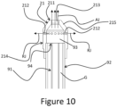
- the radial jet RJ is indicated in Figures 9 and 10 .
- the nozzle 21 has at least one axial hole 213 positioned at the axial end 211; in other words, the axial end 211 has the axial hole 213, which is for dispensing an axial jet AJ of the rinsing mixture RF from the mixing chamber 93.
- the axial jet is indicated in Figures 9 and 10 .
- the nozzle 21 is configured to eject both axial and radial jets AJ, RJ to improve the rinsing effect of the rinsing unit 2.
- the radial jets RJ are directed directly towards the lateral surfaces of the container 3, so that the latter is subject to a greater pressure of the rinsing mixture RF corresponding to a more powerful rinsing effect.
- the radial holes 212 provides a pressure drop to the axial flow of the rinsing mixture RF within the mixing chamber 93, so that the radially inner flow of the gaseous fluid is invited to expand radially, which is beneficial for the mixing with the radially outer flow of the liquid fluid.
- This mixing effect clearly also reflects into an improvement of the rinsing effect of the rinsing unit 2.
- the nozzle 21 comprises two axial sectors 214, 215 respectively defining the radial holes 212 and the axial hole 213.
- the axial sector 214 is arranged between the other axial sector 215 and the spraying tube 9 on which the nozzle 21 is mounted at the axial end 94.
- the axial sector 215 is more axially tapered than the axial sector 214 and narrowing towards the axial end 211.
- the axial sector 214 is substantially cylindrical, namely having cross sections with constant dimensions along axis X.
- the axial sector 215 is frustum-conical shaped, namely having cross sections with decreasing dimensions along axis X towards the axial end 211.
- the mostly gaseous fluid core tends to radially expand along axis X, whereas the radial dimensions of the mostly liquid surrounding ring is narrowed by the tapering inner lateral surface of the axial sector 215, so that the radially outer fluid flow is accelerated, in particular due to a Venturi-kind effect.
- the acceleration of the radially outer fluid through the axial hole 213 is beneficial for the rinsing effect of the rinsing unit 2.
- the rinsing mixture RF is forced to better lap the inner lateral surfaces of the container 3, thanks to the fluid core that pushes the radially outer fluid radially outward.
- the nozzle 21 is preferably movable in a vertical direction, parallel to the axis X from a lowered rest position, in which the nozzle 21 is arranged outside the container 3, to an intermediate position in which the nozzle 21 enters the container 3 and to a raised work position, in which the nozzle 21 projects inside the container 3; and vice versa from the raised work position to lowered rest position.
- the nozzle 21 is indeed moved back down in the vertical direction to disengage the container 3 for draining the rinsing mixture RF out of the container 3.
Landscapes
- Engineering & Computer Science (AREA)
- Mechanical Engineering (AREA)
- Filling Of Jars Or Cans And Processes For Cleaning And Sealing Jars (AREA)
Abstract
A rinsing unit (2) for rinsing a container (3) in a rinsing machine (1) is configured for rinsing internally the container (3) by means of a nozzle (21), the unit (2) comprising the respective nozzle (21) and a spraying tube (9), the tube (9) comprising an internal pipe (91) for conveying a gas and an external pipe (92) which is coaxial with respect to the internal pipe (91) and surrounds the internal pipe (91) for conveying a liquid in the radial gap (G) between the pipes (91, 92), wherein the nozzle (21) is mounted on the axial end (94) of the spraying tube (9) to define a mixing chamber (93) which is axially interposed between an axial end (211) of the nozzle (21) and the axial end (94) of the spraying tube (9), the nozzle (21) having radial holes (212) for dispensing from said chamber (93) a radial jet (RJ) of a mixture of said gas and liquid and at least one axial hole (213) for dispensing from said chamber (93) an axial jet (AJ) of said mixture, the axial hole (213) being positioned at said axial end (211) of the nozzle (21).
Description
- The present invention relates to a rinsing machine for rinsing containers in the field of packaging pourable products by means of containers, a rinsing unit which can be used in the rinsing machine, and a packaging apparatus comprising the rinsing machine.
- In the general field of packaging pourable products by means of containers, in particular in case of plastic containers, it is known the use of rinsing machines for rinsing the formed containers before the filling thereof.
- Current solutions are opened to improvements, in particular for enhancing the rinsing effect obtained on each rinsed container.
- A rinsing unit according to any of the appended unit claims or according to present description allows to improve the rinsing effect.
- A rinsing machine according to any of the appended machine claims or according to present description comprises a rinsing unit according to any of the appended unit claims or according to present description.
- A packaging apparatus according to any of the appended apparatus claims or according to present description comprises a rinsing machine according to any of the appended machine claims or according to present description.
- The following brief description of the drawings and detailed description of the invention will be referred to respective example embodiments of a rinsing unit according to present description, a rinsing machine according to present description and a packaging apparatus according to present description.
- The following detailed description will be referred to the accompanying drawings, in which:
-
Figure 1 is a perspective view of a rinsing machine comprising a rinsing unit according to the invention; -
Figure 2 is a top schematic view of the rinsing machine; -
Figure 3 is a perspective view of a part of the rinsing machine; -
Figure 4 is a graph showing a time trend related to a rinsing treatment performed by the rinsing unit; -
Figure 5 is a perspective view of a part of the rinsing unit; -
Figure 6 is a detail ofFigure 5 , in an enlarged scale; -
Figure 7 is a longitudinal cross section of the part shown inFigure 5 ; -
Figure 8 is a cut-away view of an end sector of the part shown inFigure 5 ; and -
Figure 9 is a perspective view of the rinsing unit during the rinsing treatment; -
Figure 10 is another a cut-away view of the end sector of the part shown inFigure 5 . - In
Figure 1 ,number 1 indicates, as a whole, a rotary rinsing machine for rinsingcontainers 3 for containing pourable products, in particular pourable food products. Thecontainers 3 are for example for containing a pourable carbonated food product such as sparkling water, carbonated drinks, etc. Advantageously, therinsing machine 1 is in particular configured to be used in a packaging apparatus for packaging a carbonated pourable product by means ofbottles 3, forexample PET bottles 3. - The
rinsing machine 1 comprises a plurality ofrinsing units 2. Therinsing machine 1 is configured so that thecontainers 3 are sequentially rinsed by means ofrespective rinsing units 2. Eachrinsing unit 2 is configured for internally rinsing thecontainer 3 by means of arespective nozzle 21, which is configured to adopt an active condition, in which it dispenses a rinsing mixture, and an inactive condition, in which it does not dispense any rinsing mixture. Eachrinsing unit 5 comprises therespective nozzle 21. Therinsing machine 1 is configured so that eachcontainer 2 is rinsed by at least automatically and intermittently switching therespective nozzle 21 between said active condition and said inactive condition. The rinsing mixture is indicated with RF inFigure 3 . - Each time the
nozzle 21 adopts the active condition, there is at least one respective peak of flow rate of the rinsing mixture. For each switching from inactive condition to active condition, there is at least one peak. Therefore, the rinsing effect is improved by the plurality of peaks of rinsing mixture. - Each
nozzle 21 is configured to adopt a variable degree of penetration Z in thecontainer 2. Therinsing machine 1 is configured so that the degree of penetration Z follows a time trend TT during the rinsing treatment comprising an upward stretch US, during which the degree of penetration Z increases, and a downward stretch DS, during which the degree of penetration Z decreases. Therinsing machine 1 is configured so that thenozzle 21 is intermittently switched between said active condition and inactive condition along at least one of said upward stretch US and downward stretch DS. Preferably, thenozzle 21 is switched intermittently along at least each of said upward and downward stretches US and DS. The time trend TT is shown inFigure 4 . - In this way the beneficial effect of the intermittent switching is obtained while the
nozzle 21 is crossing different degrees of penetration, to make the improvement of the rinsing effect also more uniform along the longitudinal extension of the container. - The time trend TT comprises a constant stretch CS along which the degree of penetration Z is constant. The
rinsing machine 1 is configured so that thenozzle 21 is intermittently switched between said active and inactive conditions along at least said constant stretch CS. In this way the benefit of the intermittent switching is furtherly enhanced. The constant stretch CS can correspond to the maximum degree of penetration, which can be for example 0,13 meters. - Each
unit 2 comprises agripper 22 for gripping the container. Themachine 1 comprises afirst cam 7 for overturing eachgripped container 2, so that the rinsing is performed by thenozzle 21 in theoverturned container 2. Themachine 1 comprises asecond cam 8 for regulating said time trend TT of the degree of penetration Z of thenozzle 21 in theoverturned container 2. Thefirst cam 7 and thesecond cam 8 are indicated at least in part inFigures 1 and 3 . - Each
rinsing unit 5 comprises a respective first cam follower for interacting with saidfirst cam 7 to overturn the container and a respective second cam follower for interacting with saidsecond cam 8 for regulating said degree of penetration. - The
machine 1 comprises aconveyor 4 configured to sequentially convey eachrinsing unit 2 through aninput station 5 for receiving thecontainer 2 to be rinsed, a rinsing path RP along which the rinsing occurs, and anoptout station 6 for releasing the rinsedcontainer 2. Theconveyor 4 comprises a carousel which is rotatable around a central axis X. - The
rinsing machine 1 is configured so that the active condition of eachnozzle 21 corresponds to a plurality offirst sectors 31 of the rinsing path RP, which are alternated with a plurality ofsecond sectors 32 of the rinsing path RP. The second sectors S2 correspond to the inactive condition of eachnozzle 21. Thefirst sectors 31 and thesecond sectors 32 are shown inFigure 2 . - Each
first sector 31 corresponds to an active period T1 of thenozzle 21, during which thenozzle 21 adopts the active condition, and eachsecond sector 32 corresponds to an inactive period T2 of thenozzle 21, during which thenozzle 21 adopts the inactive condition. Therinsing machine 1 is configured to allow a user to set the duration of both active and inactive periods T1 and T2. The active periods T1 and the inactive periods T2 are indicated along the abscissa axis inFigure 4 . Each active period T1 corresponds to a rinsing pulse. Therefore, eachrinsing unit 2 is configured for performing a pulsed rinsing treatment in the respective container. - The inactive periods allow the rinsing mixture to be at least partially drained from the container between two different and subsequent active periods. In this way, for each active period, the rinsing mixture is reintroduced in a container which is less filled by the same rinsing mixture, to improve the rinsing effect. In fact, the rinsing mixture that is newly introduced flows in a container in which there is less rinsing mixture than if the same rinsing mixture was introduced in an uninterrupted manner, so that the interference between the previous rinsing mixture and the flow of the new rinsing mixture is reduced.
- The value of the duration of each active period T1 can fall between for example 0,3 seconds and 0,5 seconds, or between 0,35 seconds and 0,45 seconds. The value of duration of each active period T1 can be for example 0,4 seconds.
- In this way, an optimal trade off is obtained between the need of exploiting a high number of peaks or pulses of the flow rate of rinsing mixture, and the need of reducing consumption. Also, an optimal trade off is obtained between the need of increasing the number of peaks or pulses of the flow rate of rinsing mixture, and the need of reducing the stress on the involved components of the machine.
- The value of the duration of each inactive period T2 can fall between for example 0,1 seconds and 0,3 seconds, or between 0,15 seconds and 0,25 seconds. The value of duration of each inactive period T2 can be for example 0,2 seconds. In this way an optimal trade off is obtained between the need of having many peaks or pulses of flow rate and the need of increasing the draining effect on the rinsing mixture between each couple of subsequent pulses.
- The value of total duration of the rinsing treatment, including active periods and inactive periods, can fall between 6,5 seconds and 13,5 seconds, or between 7 seconds and 11 seconds.
- The apparatus is configured for the packaging of pourable products by means of
containers 3. Preferably, the apparatus is configured for packaging a pourable food product by means ofplastic bottles 3. The apparatus comprises a forming machine for sequentially forming thecontainers 3. The forming machine can be for example a blowing machine, for example a blow molding machine. The apparatus comprises the rinsingmachine 1, for sequentially rinsing the formedcontainers 3. The apparatus comprises a filling machine for sequentially filling the rinsedcontainers 3 with the pourable product. The rinsingmachine 1 is configured for performing the pulsed rinsing treatment described above, which is in particular advantageous in case between the forming machine and the rinsing machine there is also a coating machine for coating the inner surface of each container, for example a plasma coating machine. In fact, the improvement of the rinsing effect is in particular useful to reduce possible residuals of material of the coating. The coating serves in particular to reduce migration of gas through the wall of the container. Therefore, the rinsingmachine 1 is in particular useful in case the containers are for containing a carbonated food product, like for example a carbonated beverage. - Each
rinsing unit 2 comprises a sprayingtube 9 with aninternal pipe 91 for conveying a gaseous fluid and anexternal pipe 92, which is coaxial with respect to theinternal pipe 91 and surrounds theinternal pipe 91 for conveying a liquid fluid in the radial gap G between the internal andexternal pipes - The gaseous fluid flowing through the
internal pipe 91 is pressurized, i.e., a distributor delivers the gaseous fluid to theinternal pipe 91 with a pressure which is greater than atmospheric pressure. - The rinsing fluid and the gaseous fluid may be for example water and air, respectively.
- The spraying
tube 9 extends along an axis thereof between two opposites axial ends 94, 95. - The
axial end 95 receives the gaseous fluid in theinternal pipe 91 and the liquid fluid in the radial gap G from the distributor, which may be arranged substantially at the center of the carousel. In particular, theaxial end 95 extends radially with respect to the axis X, more preferably radially toward the distributor. The gaseous fluid may be air. The liquid fluid may be water. - The
axial end 94 extends parallel to the axis X; in particular, the sprayingtube 9 includes an intermediate axial portion between the axial ends 94, 95, the intermediate portion extending according substantially to a U shape to join the axial ends 94, 95 to each other. - The
nozzle 21 is mounted on theaxial end 94 of the sprayingtube 9 to receive both the liquid and the gaseous fluid from the sprayingtube 9. The rinsing mixture comprises the liquid fluid and the gaseous fluid, and therefore for example air and water. - The
nozzle 21 communicates with theaxial end 94. More precisely, thenozzle 21 internally defines a mixingchamber 93, which communicates with theaxial end 94. - In this manner, the mixing
chamber 93 receives the liquid and the gaseous fluid from the sprayingtube 9, so that the liquid and the gaseous fluid mix to each other within the mixingchamber 93. - Actually, due to the configuration of the spraying
tube 9 with the internal andexternal pipes chamber 93 radially surrounding an axial flow of the pressurized gaseous fluid incoming in the mixingchamber 93 from theinternal pipe 91. - Therefore, an inner radial portion of the mixing
chamber 93 is axially traversed conceptually by a first fluid flow containing more gaseous fluid than liquid fluid, whereas an outer radial portion of the mixingchamber 93 is axially traversed conceptually by a second fluid flow containing more liquid fluid than gaseous fluid, even if no actual separation or boundaries can be observed between the first and the second fluid flow. Indeed, a full mixture of the liquid and gaseous fluids occurs within the mixingchamber 93, even if the distribution of the liquid and gaseous phase within the rinsing mixture RF is not equal in the inner and the outer radial portions of the mixingchamber 93. - In other words, the rinsing mixture RF has a radially inner fluid flow defining a fluid core, comprising more gaseous phase than liquid phase, and a radially outer fluid flow defining a fluid ring surrounding the fluid core about axis X and comprising more liquid phase than gaseous phase.
- Therefore, the rinsing mixture RF comprises a biphasic fluid comprising a gaseous and a liquid phase mixed to each other, for example air and water.
- The
nozzle 21 has anaxial end 211 and a further opposite axial end communicating with the sprayingtube 9. - Therefore, the mixing
chamber 93 is axially interposed between the axial ends 94, 211. - In addition, the
nozzle 21 comprises a plurality ofradial holes 212 for dispensing radial jets RJ of the mixture from the mixingchamber 93. In particular, at least a portion of theradial holes 212 is arranged according to a circular pattern on an orthogonal plane to axis X. More in particular, this portion of theradial holes 212 is angularly distributed around axis X in a uniform manner. The radial jet RJ is indicated inFigures 9 and10 . - Furthermore, the
nozzle 21 has at least oneaxial hole 213 positioned at theaxial end 211; in other words, theaxial end 211 has theaxial hole 213, which is for dispensing an axial jet AJ of the rinsing mixture RF from the mixingchamber 93. The axial jet is indicated inFigures 9 and10 . - In this manner, the
nozzle 21 is configured to eject both axial and radial jets AJ, RJ to improve the rinsing effect of therinsing unit 2. - Indeed, in addition to the axial jet AJ, the radial jets RJ are directed directly towards the lateral surfaces of the
container 3, so that the latter is subject to a greater pressure of the rinsing mixture RF corresponding to a more powerful rinsing effect. - Furthermore, the radial holes 212 provides a pressure drop to the axial flow of the rinsing mixture RF within the mixing
chamber 93, so that the radially inner flow of the gaseous fluid is invited to expand radially, which is beneficial for the mixing with the radially outer flow of the liquid fluid. This mixing effect clearly also reflects into an improvement of the rinsing effect of therinsing unit 2. - In addition, the
nozzle 21 comprises twoaxial sectors radial holes 212 and theaxial hole 213. Theaxial sector 214 is arranged between the otheraxial sector 215 and the sprayingtube 9 on which thenozzle 21 is mounted at theaxial end 94. - Conveniently, the
axial sector 215 is more axially tapered than theaxial sector 214 and narrowing towards theaxial end 211. - In the embodiment shown, the
axial sector 214 is substantially cylindrical, namely having cross sections with constant dimensions along axis X. Theaxial sector 215 is frustum-conical shaped, namely having cross sections with decreasing dimensions along axis X towards theaxial end 211. - In this manner, the mostly gaseous fluid core tends to radially expand along axis X, whereas the radial dimensions of the mostly liquid surrounding ring is narrowed by the tapering inner lateral surface of the
axial sector 215, so that the radially outer fluid flow is accelerated, in particular due to a Venturi-kind effect. - The acceleration of the radially outer fluid through the
axial hole 213 is beneficial for the rinsing effect of therinsing unit 2. - Furthermore, the rinsing mixture RF is forced to better lap the inner lateral surfaces of the
container 3, thanks to the fluid core that pushes the radially outer fluid radially outward. - The
nozzle 21 is preferably movable in a vertical direction, parallel to the axis X from a lowered rest position, in which thenozzle 21 is arranged outside thecontainer 3, to an intermediate position in which thenozzle 21 enters thecontainer 3 and to a raised work position, in which thenozzle 21 projects inside thecontainer 3; and vice versa from the raised work position to lowered rest position. Once thecontainer 3 is rinsed, thenozzle 21 is indeed moved back down in the vertical direction to disengage thecontainer 3 for draining the rinsing mixture RF out of thecontainer 3.
Claims (11)
- Rinsing unit (2) for rinsing a container (3) in a rinsing machine (1);wherein the unit (2) is configured for rinsing internally the container (3) by means of a nozzle (21), the unit (2) comprising the respective nozzle (21);wherein the unit (2) comprises a spraying tube (9), the tube (9) comprising an internal pipe (91) for conveying a gas and an external pipe (92) which surrounds the internal pipe (91) for conveying a liquid in the radial gap (G) between the pipes (91, 92);wherein the nozzle (21) is mounted on the axial end (94) of the spraying tube (9) to define a mixing chamber (93) which is axially interposed between an axial end (211) of the nozzle (21) and the axial end (94) of the spraying tube (9), said nozzle (21) comprising radial holes (212) for dispensing from said chamber (93) at least one radial jet (RJ) of a rinsing mixture of said gas and liquid and at least one axial hole (213) for dispensing from said chamber (93) an axial jet (AJ) of said mixture, the axial hole (213) being positioned at said axial end (211) of the nozzle (21).
- Rinsing unit (2) according to claim 1, wherein the nozzle (21) comprises a first axial sector (214) defining said radial holes (212) and a second axial sector (215) defining said axial hole (213), the second axial sector (215) being more axially tapered than said first axial sector (214) and narrowing towards said axial end (211) .
- Rinsing machine (1) for rinsing containers (3), comprising a plurality of rinsing unit (2), each rinsing unit (2) being according to any of Claim 1 or 2, the machine (1) being configured so that the containers (3) are sequentially rinsed by means of respective rinsing units (2).
- Rinsing machine (1) according to Claim 3, wherein each nozzle (21) is configured to adopt an active condition, in which it dispenses the rinsing mixture, and an inactive condition, in which it does not dispense any rinsing mixture, each rinsing unit (2) comprising the respective nozzle (21); and wherein the rinsing machine (1) is configured so that each container (3) is rinsed by at least automatically and intermittently switching the respective nozzle (21) between said active condition and said inactive condition.
- A rinsing machine (1) according to claim 4, wherein each nozzle (21) is configured to adopt a variable degree of penetration (Z) in the container (2); the rinsing machine (1) is configured so that the degree of penetration (Z) follows a time trend (TT) during the rinsing treatment comprising an upward stretch (US), during which the degree of penetration (Z) increases, and a downward stretch (DS), during which the degree of penetration (Z) decreases; the rinsing machine (1) is configured so that the nozzle (21) is intermittently switched between said active condition and inactive condition along at least one of said upward and downward stretches (US, DS), preferably along at least each of said upward and downward stretches (US, DS).
- A rinsing machine (1) according to claim 5, wherein said time trend (TT) comprises a constant stretch (CS) along which the degree of penetration (Z) is constant; the rinsing machine (1) is configured so that the nozzle (21) is intermittently switched between said active condition and inactive condition along at least said constant stretch (CS).
- A rinsing machine (1) according to claims 5 or 6, wherein each unit (2) comprises a gripper (22) for gripping the container and the machine (1) comprises a first cam (7) for overturing each gripped container (3), so that the rinsing is performed by the nozzle (21) in the overturned container (3), and a second cam (8) for regulating said time trend (TT) of the degree of penetration (Z) of the nozzle (21) in the overturned container (2) .
- A rinsing machine (1) according to any of Claims from 5 to 7, wherein each rinsing unit (5) comprises a first cam follower for interacting with said first cam (7) to overturn the container (2) and a second cam follower for interacting with said second cam (8) for regulating said degree of penetration (Z).
- A rinsing machine (1) according to anyone of the previous claims from 3 to 8, comprising a conveyor (4) configured to sequentially convey each rinsing unit (2) through an input station (5) for receiving the container (2) to be rinsed, a rinsing path (RP) along which the rinsing treatment occurs, and an optout station (6) for releasing the rinsed container (2); the rinsing machine (1) is configured so that the active condition of each nozzle (21) corresponds to a plurality of first sectors (31) of the rinsing path (RP) which are alternated with a plurality of second sectors (32) of the rinsing path (RP), said second sectors (32) corresponding to the inactive condition of each nozzle (21).
- A rinsing machine (1) according to claim 9, wherein each first sector (31) corresponds to an active period (T1) of the nozzle (21), during which the nozzle (21) adopts the active condition, and each second sector (32) corresponds to an inactive period (T2) of the nozzle (21), during which the nozzle (21) adopts the inactive condition; the rinsing machine (1) is configured to allow a user to set the duration of both active and inactive periods (T1, T2).
- An apparatus for the packaging of pourable products by means of containers (2), preferably a pourable food product by means of plastic bottles (2), comprising a forming machine for sequentially forming the containers (2); a rinsing machine (1) according to any one of the previous claims from 3 to 10, for sequentially rinsing the formed containers (2); and a filling machine for sequentially filling the rinsed containers (2) with the pourable product.
Priority Applications (2)
| Application Number | Priority Date | Filing Date | Title |
|---|---|---|---|
| EP23209307.0A EP4552760A1 (en) | 2023-11-13 | 2023-11-13 | Rinsing machine with double direction nozzles |
| PCT/EP2024/080072 WO2025103729A1 (en) | 2023-11-13 | 2024-10-24 | Rinsing machine with double direction nozzles |
Applications Claiming Priority (1)
| Application Number | Priority Date | Filing Date | Title |
|---|---|---|---|
| EP23209307.0A EP4552760A1 (en) | 2023-11-13 | 2023-11-13 | Rinsing machine with double direction nozzles |
Publications (1)
| Publication Number | Publication Date |
|---|---|
| EP4552760A1 true EP4552760A1 (en) | 2025-05-14 |
Family
ID=88793057
Family Applications (1)
| Application Number | Title | Priority Date | Filing Date |
|---|---|---|---|
| EP23209307.0A Pending EP4552760A1 (en) | 2023-11-13 | 2023-11-13 | Rinsing machine with double direction nozzles |
Country Status (2)
| Country | Link |
|---|---|
| EP (1) | EP4552760A1 (en) |
| WO (1) | WO2025103729A1 (en) |
Citations (7)
| Publication number | Priority date | Publication date | Assignee | Title |
|---|---|---|---|---|
| CA900829A (en) * | 1972-05-23 | Barry-Wehmiller Company | Container rinsing and treating apparatus | |
| US4125120A (en) * | 1976-02-23 | 1978-11-14 | Abbott Laboratories | Washing apparatus for containers |
| JPS602487A (en) * | 1983-06-14 | 1985-01-08 | 日立造船株式会社 | Rotary type rinser |
| EP0381841A1 (en) * | 1989-01-27 | 1990-08-16 | Robert Bosch Gmbh | Method and device for cleaning and sterilizing containers |
| CN201086082Y (en) * | 2007-08-20 | 2008-07-16 | 温州市金瓯轻工机械有限公司 | Flushing mechanism of full-automatic turning bottle flushing device for wide neck container |
| JP2010179927A (en) * | 2009-02-04 | 2010-08-19 | Mitsubishi Heavy Industries Food & Packaging Machinery Co Ltd | Foreign matter removing device, and electron beam sterilizing system |
| JP2012170852A (en) * | 2011-02-18 | 2012-09-10 | Mitsubishi Heavy Industries Food & Packaging Machinery Co Ltd | Foreign matter removing device |
-
2023
- 2023-11-13 EP EP23209307.0A patent/EP4552760A1/en active Pending
-
2024
- 2024-10-24 WO PCT/EP2024/080072 patent/WO2025103729A1/en active Pending
Patent Citations (7)
| Publication number | Priority date | Publication date | Assignee | Title |
|---|---|---|---|---|
| CA900829A (en) * | 1972-05-23 | Barry-Wehmiller Company | Container rinsing and treating apparatus | |
| US4125120A (en) * | 1976-02-23 | 1978-11-14 | Abbott Laboratories | Washing apparatus for containers |
| JPS602487A (en) * | 1983-06-14 | 1985-01-08 | 日立造船株式会社 | Rotary type rinser |
| EP0381841A1 (en) * | 1989-01-27 | 1990-08-16 | Robert Bosch Gmbh | Method and device for cleaning and sterilizing containers |
| CN201086082Y (en) * | 2007-08-20 | 2008-07-16 | 温州市金瓯轻工机械有限公司 | Flushing mechanism of full-automatic turning bottle flushing device for wide neck container |
| JP2010179927A (en) * | 2009-02-04 | 2010-08-19 | Mitsubishi Heavy Industries Food & Packaging Machinery Co Ltd | Foreign matter removing device, and electron beam sterilizing system |
| JP2012170852A (en) * | 2011-02-18 | 2012-09-10 | Mitsubishi Heavy Industries Food & Packaging Machinery Co Ltd | Foreign matter removing device |
Also Published As
| Publication number | Publication date |
|---|---|
| WO2025103729A1 (en) | 2025-05-22 |
Similar Documents
| Publication | Publication Date | Title |
|---|---|---|
| CN101505885B (en) | Method for treating bottles or such like containers in a cleaning machine and also cleaning machine | |
| US8480813B2 (en) | Method of cleaning returned beverage bottles in a bottle filling plant, a method of introducing treatment fluid into containers to remove contaminants therefrom in a container filling plant, and an arrangement therefor | |
| CN103879599B (en) | Device and method for sterilizing containers | |
| EP3348377B1 (en) | Receptacle conveying and cooling apparatus, a method of operating such a receptacle conveying and cooling apparatus and a receptacle treatment machine having such a receptacle conveying and cooling apparatus | |
| US7814940B2 (en) | Beverage filling plant for filling beverage bottles or containers with a liquid beverage filling material having a beverage bottle or container treatment arrangement and a method of operation thereof | |
| US20250187894A1 (en) | System for introducing an additive into a container comprising a static microdoser | |
| EP3386903B1 (en) | Bottling machine comprising at least two micro-carousels for additive fluids, and related method | |
| EP3947161A1 (en) | Multi-nozzle dosing system | |
| WO2025103729A1 (en) | Rinsing machine with double direction nozzles | |
| US5038548A (en) | Defoaming method and apparatus | |
| EP0996584B1 (en) | Machine and method for filling containers, in particular bottles | |
| EP4552759A1 (en) | Rinsing machine configured for pulsed rinsing treatment | |
| US20200240010A1 (en) | Device for internally coating containers | |
| CN103129780A (en) | Device and method for sterilizing container, and drink filling and/or drink container manufacturing device | |
| JP7661056B2 (en) | nozzle | |
| US20110262615A1 (en) | Apparatus for the Production of a Sparkling Beverage | |
| JP2004161350A (en) | Gas displacement device of capper | |
| WO2022233899A1 (en) | Nozzle for a static microdoser and system comprising a microdoser with such nozzle for introducing an additive into a container | |
| US12351444B2 (en) | System comprising a static microdoser for introducing an additive into a container | |
| JP4300708B2 (en) | Rotary filling device | |
| WO2026002376A1 (en) | Filling device for long tube contact filling with mobile evacuation group | |
| WO2026002377A1 (en) | Filling device for long tube contact filling with long dummy bottle | |
| JPH10211474A (en) | Container cleaning device | |
| JP2002128020A (en) | Method and apparatus for filling container with liquid nitrogen | |
| JP2003079353A (en) | Container pushing device in retort device |
Legal Events
| Date | Code | Title | Description |
|---|---|---|---|
| PUAI | Public reference made under article 153(3) epc to a published international application that has entered the european phase |
Free format text: ORIGINAL CODE: 0009012 |
|
| STAA | Information on the status of an ep patent application or granted ep patent |
Free format text: STATUS: THE APPLICATION HAS BEEN PUBLISHED |
|
| AK | Designated contracting states |
Kind code of ref document: A1 Designated state(s): AL AT BE BG CH CY CZ DE DK EE ES FI FR GB GR HR HU IE IS IT LI LT LU LV MC ME MK MT NL NO PL PT RO RS SE SI SK SM TR |
|
| STAA | Information on the status of an ep patent application or granted ep patent |
Free format text: STATUS: REQUEST FOR EXAMINATION WAS MADE |
|
| 17P | Request for examination filed |
Effective date: 20251106 |
|
| STAA | Information on the status of an ep patent application or granted ep patent |
Free format text: STATUS: EXAMINATION IS IN PROGRESS |