EP4552759A1 - Rinsing machine configured for pulsed rinsing treatment - Google Patents
Rinsing machine configured for pulsed rinsing treatment Download PDFInfo
- Publication number
- EP4552759A1 EP4552759A1 EP23209305.4A EP23209305A EP4552759A1 EP 4552759 A1 EP4552759 A1 EP 4552759A1 EP 23209305 A EP23209305 A EP 23209305A EP 4552759 A1 EP4552759 A1 EP 4552759A1
- Authority
- EP
- European Patent Office
- Prior art keywords
- rinsing
- machine
- nozzle
- container
- containers
- Prior art date
- Legal status (The legal status is an assumption and is not a legal conclusion. Google has not performed a legal analysis and makes no representation as to the accuracy of the status listed.)
- Withdrawn
Links
Images


Classifications
-
- B—PERFORMING OPERATIONS; TRANSPORTING
- B08—CLEANING
- B08B—CLEANING IN GENERAL; PREVENTION OF FOULING IN GENERAL
- B08B9/00—Cleaning hollow articles by methods or apparatus specially adapted thereto
- B08B9/08—Cleaning containers, e.g. tanks
- B08B9/20—Cleaning containers, e.g. tanks by using apparatus into or on to which containers, e.g. bottles, jars, cans are brought
- B08B9/28—Cleaning containers, e.g. tanks by using apparatus into or on to which containers, e.g. bottles, jars, cans are brought the apparatus cleaning by splash, spray, or jet application, with or without soaking
- B08B9/30—Cleaning containers, e.g. tanks by using apparatus into or on to which containers, e.g. bottles, jars, cans are brought the apparatus cleaning by splash, spray, or jet application, with or without soaking and having conveyors
- B08B9/32—Rotating conveyors
-
- B—PERFORMING OPERATIONS; TRANSPORTING
- B08—CLEANING
- B08B—CLEANING IN GENERAL; PREVENTION OF FOULING IN GENERAL
- B08B9/00—Cleaning hollow articles by methods or apparatus specially adapted thereto
- B08B9/08—Cleaning containers, e.g. tanks
- B08B9/20—Cleaning containers, e.g. tanks by using apparatus into or on to which containers, e.g. bottles, jars, cans are brought
- B08B9/28—Cleaning containers, e.g. tanks by using apparatus into or on to which containers, e.g. bottles, jars, cans are brought the apparatus cleaning by splash, spray, or jet application, with or without soaking
- B08B9/34—Arrangements of conduits or nozzles
-
- B—PERFORMING OPERATIONS; TRANSPORTING
- B08—CLEANING
- B08B—CLEANING IN GENERAL; PREVENTION OF FOULING IN GENERAL
- B08B9/00—Cleaning hollow articles by methods or apparatus specially adapted thereto
- B08B9/08—Cleaning containers, e.g. tanks
- B08B9/20—Cleaning containers, e.g. tanks by using apparatus into or on to which containers, e.g. bottles, jars, cans are brought
- B08B9/42—Cleaning containers, e.g. tanks by using apparatus into or on to which containers, e.g. bottles, jars, cans are brought the apparatus being characterised by means for conveying or carrying containers therethrough
- B08B9/426—Grippers for bottles
Definitions
- the present invention relates to a rinsing machine for rinsing containers in the field of packaging pourable products by means of containers, and to a packaging apparatus comprising the rinsing machine.
- a packaging plant which has a forming machine, preferably a blowing forming machine, for sequentially forming the containers; a rinsing machine configured for sequentially rinsing the formed containers and arranged downstream of the forming machine along a packaging path; and a filling machine arranged downstream of the rinsing machine along the packaging path for sequentially filling the rinsed containers with the pourable carbonated food product.
- a further object of the present invention is to provide a packaging apparatus addressing the drawbacks described above and, in particular, being easy and economical to be manufactured.
- number 1 indicates, as a whole, a rotary rinsing machine for rinsing containers 2 for containing pourable products, in particular pourable food products.
- the containers 2 are for example for containing a pourable carbonated food product such as sparkling water, carbonated drinks, etc.
- the rinsing machine 1 is in particular configured to be used in a packaging apparatus for packaging a carbonated pourable product by means of bottles 2, for example PET bottles 2.
- the rinsing machine 1 comprises a plurality of rinsing units 5.
- the rinsing machine 1 is configured so that the containers 2 are sequentially rinsed by means of respective rinsing units 5.
- Each rinsing unit 5 is configured for internally rinsing the container 2 by means of a respective nozzle 14, which is configured to adopt an active condition, in which it dispenses a rinsing mixture, and an inactive condition, in which it does not dispense any rinsing mixture.
- Each rinsing unit 5 comprises the respective nozzle 14.
- the rinsing machine 1 is configured so that each container 2 is rinsed by at least automatically and intermittently switching the respective nozzle 14 between said active condition and said inactive condition.
- the rinsing mixture may comprise for example air and water.
- Each nozzle 14 is configured to adopt a variable degree of penetration Z in the container 2.
- the rinsing machine 1 is configured so that the degree of penetration Z follows a time trend TT during the rinsing treatment comprising an upward stretch US, during which the degree of penetration Z increases, and a downward stretch DS, during which the degree of penetration Z decreases.
- the time trend TT comprises a constant stretch CS along which the degree of penetration Z is constant.
- the rinsing machine 1 is configured so that the nozzle 14 is intermittently switched between said active condition and inactive condition along at least said constant stretch CS. In this way the benefit of the intermittent switching is furtherly enhanced.
- the constant stretch CS can correspond to the maximum degree of penetration, which can be for example 0,13 meters.
- Each unit 5 comprises a gripper 8 for gripping the container.
- the machine 1 comprises a first cam 11 for overturing each gripped container 2, so that the rinsing is performed by the nozzle 14 in the overturned container 2.
- the machine 1 comprises a second cam 13 for regulating said time trend TT of the degree of penetration Z of the nozzle 14 in the overturned container 2.
- the first cam 11 and the second cam 13 are shown at least in part in Figures 1 and 2 .
- Each rinsing unit 5 comprises a respective first cam follower 10 for interacting with said first cam 11 to overturn the container and a respective second cam follower 12 for interacting with said second cam 13 for regulating said degree of penetration.
- the machine 1 comprises a conveyor 3 configured to sequentially convey each rinsing unit 5 through an input station 6 for receiving the container 2 to be rinsed, a rinsing path RP along which the rinsing occurs, and an optout station 7 for releasing the rinsed container 2.
- the conveyor 3 comprises a carousel 4 which is rotatable around a central axis X.
- the rinsing machine 1 is configured so that the active condition of each nozzle 14 corresponds to a plurality of first sectors S1 of the rinsing path RP, which are alternated with a plurality of second sectors S2 of the rinsing path RP.
- the second sectors S2 correspond to the inactive condition of each nozzle 14.
- the first sectors S1 and the second sectors S2 are shown in Figure 3 .
- Each first sector S1 corresponds to an active period T1 of the nozzle 14, during which the nozzle 14 adopts the active condition
- each second sector S2 corresponds to an inactive period T2 of the nozzle 14, during which the nozzle 14 adopts the inactive condition.
- the rinsing machine 1 is configured to allow a user to set the duration of both active and inactive periods T1 and T2.
- the active period T1 and the inactive periods T2 are indicated along the abscissa axis of Figure 4 .
- Each active period T1 corresponds to a rinsing pulse. Therefore, each rinsing unit 5 is configured for performing a pulse rinsing treatment in the respective container.
- the inactive periods allow the rinsing mixture to be at least partially drained from the container between two different and subsequent active periods. In this way, for each active period, the rinsing mixture is reintroduced in a container which is less filled by the same rinsing mixture, to improve the rinsing effect. In fact, the rinsing mixture that is newly introduced flows in a container in which there is less rinsing mixture than if the same rinsing mixture was introduced in an uninterrupted manner, so that the interference between the previous rinsing mixture and the flow of the new rinsing mixture is reduced.
- the value of the duration of each active period T1 can fall between for example 0,3 seconds and 0,5 seconds, or between 0,35 seconds and 0,45 seconds.
- the value of duration of each active period T1 can be for example 0,4 seconds.
- an optimal trade off is obtained between the need of exploiting a high number of peaks or pulses of the flow rate of rinsing mixture, and the need of reducing consumption. Also, an optimal trade off is obtained between the need of increasing the number of peaks or pulses of the flow rate of rinsing mixture, and the need of reducing the stress on the involved components of the machine.
- the value of the duration of each inactive period T2 can fall between for example 0,1 seconds and 0,3 seconds, or between 0,15 seconds and 0,25 seconds.
- the value of duration of each inactive period T2 can be for example 0,2 seconds. In this way an optimal trade off is obtained between the need of having many peaks or pulses of flow rate and the need of increasing the draining effect of rinsing mixture between each couple of subsequent pulses.
- the value of total duration of the rinsing treatment, including active periods and inactive periods, can fall between 6,5 seconds and 13,5 seconds, or between 7 seconds and 11 seconds.
- the apparatus is configured for the packaging of pourable products by means of containers 2.
- the apparatus is configured for packaging a pourable food product by means of plastic bottles 2.
- the apparatus comprises a forming machine for sequentially forming the containers 2.
- the forming machine can be for example a blowing machine, for example a blow molding machine.
- the apparatus comprises the rinsing machine 1, for sequentially rinsing the formed containers 2.
- the apparatus comprises a filling machine for sequentially filling the rinsed containers 2 with the pourable product.
- the rinsing machine 1 is configured for performing the pulsed rinsing treatment described above, which is in particular advantageous in case between the forming machine and the rinsing machine there is also a coating machine for coating the inner surface of each container, for example a plasma coating machine.
- the improvement of the rinsing effect is in particular useful to reduce possible residuals of material of the coating.
- the coating serves in particular to reduce migration of gas through the wall of the container. Therefore, the rinsing machine 1 is in particular useful in case the containers are for containing a carbonated food product, like for example a carbonated beverage.
Landscapes
- Engineering & Computer Science (AREA)
- Mechanical Engineering (AREA)
- Filling Of Jars Or Cans And Processes For Cleaning And Sealing Jars (AREA)
Abstract
It is described a rinsing machine (1) for rinsing containers (2), comprising a plurality of rinsing units (5), the rinsing machine (1) is configured so that the containers (2) are sequentially rinsed by means of respective rinsing units (5); wherein each rinsing unit (5) is configured for internally rinsing the container (2) by means of a nozzle (14), configured to adopt an active condition, in which it dispenses a rinsing mixture, and an inactive condition, in which it does not dispense any rinsing mixture, each rinsing unit (5) comprising the respective nozzle (14); and wherein the rinsing machine (1) is configured so that each container (2) is rinsed by at least automatically and intermittently switching the respective nozzle (14) between said active condition and said inactive condition.
Description
- The present invention relates to a rinsing machine for rinsing containers in the field of packaging pourable products by means of containers, and to a packaging apparatus comprising the rinsing machine.
- In the general field of packaging pourable carbonated food products such as sparkling water, carbonated drinks by means of containers, in particular in case of plastic bottles, the use of a packaging plant is known, which has a forming machine, preferably a blowing forming machine, for sequentially forming the containers; a rinsing machine configured for sequentially rinsing the formed containers and arranged downstream of the forming machine along a packaging path; and a filling machine arranged downstream of the rinsing machine along the packaging path for sequentially filling the rinsed containers with the pourable carbonated food product.
- Current solutions for rinsing machines are opened to improvements; in particular, the rinsing effect obtained on each rinsed container particularly needs to be enhanced.
- It is therefore an object of the present invention to provide a rinsing machine for rinsing containers addressing the drawbacks described above and, in particular, improving the rinsing effect and being easy and economical to be manufactured.
- A further object of the present invention is to provide a packaging apparatus addressing the drawbacks described above and, in particular, being easy and economical to be manufactured.
- According to the invention there are provided a rinsing machine for rinsing containers and a packaging apparatus according to the appended claims.
- A non-limiting embodiment of the present invention will be described by way of example with reference to the accompanying drawings, in which:
-
Figure 1 is a perspective view of a rinsing machine for rinsing containers for pourable food products according to the present invention; -
Figure 2 is a perspective view of a portion of the rinsing machine offigure 1 ; -
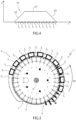
Figure 3 is a plan view of the rinsing machine offigure 1 ; -
Figure 4 is a diagram showing a time trend related to a rinsing treatment performed by a rinsing unit belonging to the rinsing machine offigure 1 . - In
Figure 1 ,number 1 indicates, as a whole, a rotary rinsing machine for rinsingcontainers 2 for containing pourable products, in particular pourable food products. Thecontainers 2 are for example for containing a pourable carbonated food product such as sparkling water, carbonated drinks, etc. Advantageously, therinsing machine 1 is in particular configured to be used in a packaging apparatus for packaging a carbonated pourable product by means ofbottles 2, forexample PET bottles 2. - The
rinsing machine 1 comprises a plurality ofrinsing units 5. Therinsing machine 1 is configured so that thecontainers 2 are sequentially rinsed by means ofrespective rinsing units 5. Eachrinsing unit 5 is configured for internally rinsing thecontainer 2 by means of arespective nozzle 14, which is configured to adopt an active condition, in which it dispenses a rinsing mixture, and an inactive condition, in which it does not dispense any rinsing mixture. Eachrinsing unit 5 comprises therespective nozzle 14. Therinsing machine 1 is configured so that eachcontainer 2 is rinsed by at least automatically and intermittently switching therespective nozzle 14 between said active condition and said inactive condition. - The rinsing mixture may comprise for example air and water.
- Each time the
nozzle 14 adopts the active condition, there is at least one respective peak of flow rate of the rinsing mixture. For each switching from inactive condition to active condition, there is at least one peak. Therefore, the rinsing effect is improved by the plurality of peaks of rinsing mixture. Eachnozzle 14 is configured to adopt a variable degree of penetration Z in thecontainer 2. Therinsing machine 1 is configured so that the degree of penetration Z follows a time trend TT during the rinsing treatment comprising an upward stretch US, during which the degree of penetration Z increases, and a downward stretch DS, during which the degree of penetration Z decreases. Therinsing machine 1 is configured so that thenozzle 14 is intermittently switched between said active condition and said inactive condition along at least one of said upward stretch US and downward stretch DS. Preferably, thenozzle 14 is switched intermittently along at least each of said upward and downward stretches US and DS. The time trend TT is shown inFigure 4 . - In this way the beneficial effect of the intermittent switching is obtained while the
nozzle 14 is crossing different degrees of penetration, to make the improvement of the rinsing effect also more uniform along the longitudinal extension of the container. - The time trend TT comprises a constant stretch CS along which the degree of penetration Z is constant. The
rinsing machine 1 is configured so that thenozzle 14 is intermittently switched between said active condition and inactive condition along at least said constant stretch CS. In this way the benefit of the intermittent switching is furtherly enhanced. The constant stretch CS can correspond to the maximum degree of penetration, which can be for example 0,13 meters. - Each
unit 5 comprises agripper 8 for gripping the container. Themachine 1 comprises afirst cam 11 for overturing eachgripped container 2, so that the rinsing is performed by thenozzle 14 in theoverturned container 2. Themachine 1 comprises asecond cam 13 for regulating said time trend TT of the degree of penetration Z of thenozzle 14 in theoverturned container 2. Thefirst cam 11 and thesecond cam 13 are shown at least in part inFigures 1 and2 . - Each
rinsing unit 5 comprises a respectivefirst cam follower 10 for interacting with saidfirst cam 11 to overturn the container and a respectivesecond cam follower 12 for interacting with saidsecond cam 13 for regulating said degree of penetration. - The
machine 1 comprises aconveyor 3 configured to sequentially convey eachrinsing unit 5 through aninput station 6 for receiving thecontainer 2 to be rinsed, a rinsing path RP along which the rinsing occurs, and anoptout station 7 for releasing the rinsedcontainer 2. Theconveyor 3 comprises acarousel 4 which is rotatable around a central axis X. - The
rinsing machine 1 is configured so that the active condition of eachnozzle 14 corresponds to a plurality of first sectors S1 of the rinsing path RP, which are alternated with a plurality of second sectors S2 of the rinsing path RP. The second sectors S2 correspond to the inactive condition of eachnozzle 14. The first sectors S1 and the second sectors S2 are shown inFigure 3 . - Each first sector S1 corresponds to an active period T1 of the
nozzle 14, during which thenozzle 14 adopts the active condition, and each second sector S2 corresponds to an inactive period T2 of thenozzle 14, during which thenozzle 14 adopts the inactive condition. Therinsing machine 1 is configured to allow a user to set the duration of both active and inactive periods T1 and T2. The active period T1 and the inactive periods T2 are indicated along the abscissa axis ofFigure 4 . Each active period T1 corresponds to a rinsing pulse. Therefore, eachrinsing unit 5 is configured for performing a pulse rinsing treatment in the respective container. - The inactive periods allow the rinsing mixture to be at least partially drained from the container between two different and subsequent active periods. In this way, for each active period, the rinsing mixture is reintroduced in a container which is less filled by the same rinsing mixture, to improve the rinsing effect. In fact, the rinsing mixture that is newly introduced flows in a container in which there is less rinsing mixture than if the same rinsing mixture was introduced in an uninterrupted manner, so that the interference between the previous rinsing mixture and the flow of the new rinsing mixture is reduced.
- The value of the duration of each active period T1 can fall between for example 0,3 seconds and 0,5 seconds, or between 0,35 seconds and 0,45 seconds. The value of duration of each active period T1 can be for example 0,4 seconds.
- In this way, an optimal trade off is obtained between the need of exploiting a high number of peaks or pulses of the flow rate of rinsing mixture, and the need of reducing consumption. Also, an optimal trade off is obtained between the need of increasing the number of peaks or pulses of the flow rate of rinsing mixture, and the need of reducing the stress on the involved components of the machine.
- The value of the duration of each inactive period T2 can fall between for example 0,1 seconds and 0,3 seconds, or between 0,15 seconds and 0,25 seconds. The value of duration of each inactive period T2 can be for example 0,2 seconds. In this way an optimal trade off is obtained between the need of having many peaks or pulses of flow rate and the need of increasing the draining effect of rinsing mixture between each couple of subsequent pulses.
- The value of total duration of the rinsing treatment, including active periods and inactive periods, can fall between 6,5 seconds and 13,5 seconds, or between 7 seconds and 11 seconds.
- The apparatus is configured for the packaging of pourable products by means of
containers 2. Preferably, the apparatus is configured for packaging a pourable food product by means ofplastic bottles 2. The apparatus comprises a forming machine for sequentially forming thecontainers 2. The forming machine can be for example a blowing machine, for example a blow molding machine. The apparatus comprises the rinsingmachine 1, for sequentially rinsing the formedcontainers 2. The apparatus comprises a filling machine for sequentially filling the rinsedcontainers 2 with the pourable product. The rinsingmachine 1 is configured for performing the pulsed rinsing treatment described above, which is in particular advantageous in case between the forming machine and the rinsing machine there is also a coating machine for coating the inner surface of each container, for example a plasma coating machine. In fact, the improvement of the rinsing effect is in particular useful to reduce possible residuals of material of the coating. The coating serves in particular to reduce migration of gas through the wall of the container. Therefore, the rinsingmachine 1 is in particular useful in case the containers are for containing a carbonated food product, like for example a carbonated beverage.
Claims (8)
- A rinsing machine (1) for rinsing containers (2), comprising a plurality of rinsing units (5), the rinsing machine (1) is configured so that the containers (2) are sequentially rinsed by means of respective rinsing units (5); wherein each rinsing unit (5) is configured for internally rinsing the container (2) by means of a nozzle (14), configured to adopt an active condition, in which it dispenses a rinsing mixture, and an inactive condition, in which it does not dispense any rinsing mixture, each rinsing unit (5) comprising the respective nozzle (14); and wherein the rinsing machine (1) is configured so that each container (2) is rinsed by at least automatically and intermittently switching the respective nozzle (14) between said active condition and said inactive condition.
- A rinsing machine (1) according to claim 1, wherein each nozzle (14) is configured to adopt a variable degree of penetration (Z) in the container (2); the rinsing machine (1) is configured so that the degree of penetration (Z) follows a time trend (TT) during the rinsing treatment comprising an upward stretch (US), during which the degree of penetration (Z) increases, and a downward stretch (DS), during which the degree of penetration (Z) decreases; the rinsing machine (1) is configured so that the nozzle (14) is intermittently switched between said active condition and inactive condition along at least one of said upward and downward stretches (US, DS), preferably along at least each of said upward and downward stretches (US, DS).
- A rinsing machine (1) according to claim 2, wherein said time trend (TT) comprises a constant stretch (CS) along which the degree of penetration (Z) is constant; the rinsing machine (1) is configured so that the nozzle (14) is intermittently switched between said active condition and inactive condition along at least said constant stretch (CS).
- A rinsing machine (1) according to claims 2 or 3, wherein each unit (5) comprises a gripper (8) for gripping the container and the machine (1) comprises a first cam (11) for overturing each gripped container (2), so that the rinsing is performed by the nozzle (14) in the overturned container (2), and a second cam (13) for regulating said time trend (TT) of the degree of penetration (Z) of the nozzle (14) in the overturned container (2).
- A rinsing machine (1) according to claims 2 or 3 or 4, wherein each rinsing unit (5) comprises a first cam follower (10) for interacting with said first cam (11) to overturn the container (2), and a second cam follower (12) for interacting with said second cam (13) for regulating said degree of penetration (Z).
- A rinsing machine (1) according to anyone of the previous claims and comprising a conveyor (3) configured to sequentially convey each rinsing unit (5) through an input station (6) for receiving the container (2) to be rinsed, a rinsing path (RP) along which the rinsing treatment occurs, and an optout station (7) for releasing the rinsed container (2); the rinsing machine (1) is configured so that the active condition of each nozzle (14) corresponds to a plurality of first sectors (S1) of the rinsing path (RP) which are alternated with a plurality of second sectors (S2) of the rinsing path (RP) corresponding to the inactive condition of each nozzle (14) .
- A rinsing machine (1) according to claim 6, wherein each first sector (S1) corresponds to an active period (T1) of the nozzle (14), during which the nozzle (14) adopts the active condition, and each second sector (S2) corresponds to an inactive period (T2) of the nozzle (14), during which the nozzle (14) adopts the inactive condition; the rinsing machine (1) is configured to allow a user to set the duration of both active and inactive periods (T1, T2).
- An apparatus for the packaging of pourable products by means of containers (2), preferably a pourable food product by means of plastic bottles (2), comprising a forming machine for sequentially forming the containers (2); a rinsing machine (1) according to any one of the previous claims, for sequentially rinsing the formed containers (2); and a filling machine for sequentially filling the rinsed containers (2) with the pourable product.
Priority Applications (1)
| Application Number | Priority Date | Filing Date | Title |
|---|---|---|---|
| EP23209305.4A EP4552759A1 (en) | 2023-11-13 | 2023-11-13 | Rinsing machine configured for pulsed rinsing treatment |
Applications Claiming Priority (1)
| Application Number | Priority Date | Filing Date | Title |
|---|---|---|---|
| EP23209305.4A EP4552759A1 (en) | 2023-11-13 | 2023-11-13 | Rinsing machine configured for pulsed rinsing treatment |
Publications (1)
| Publication Number | Publication Date |
|---|---|
| EP4552759A1 true EP4552759A1 (en) | 2025-05-14 |
Family
ID=88793089
Family Applications (1)
| Application Number | Title | Priority Date | Filing Date |
|---|---|---|---|
| EP23209305.4A Withdrawn EP4552759A1 (en) | 2023-11-13 | 2023-11-13 | Rinsing machine configured for pulsed rinsing treatment |
Country Status (1)
| Country | Link |
|---|---|
| EP (1) | EP4552759A1 (en) |
Citations (6)
| Publication number | Priority date | Publication date | Assignee | Title |
|---|---|---|---|---|
| US3111131A (en) * | 1961-03-01 | 1963-11-19 | Barry Wehmiller Mach Co | Bottle washing apparatus |
| CA900829A (en) * | 1972-05-23 | Barry-Wehmiller Company | Container rinsing and treating apparatus | |
| JPS602487A (en) * | 1983-06-14 | 1985-01-08 | 日立造船株式会社 | Rotary type rinser |
| WO2008034512A1 (en) * | 2006-09-22 | 2008-03-27 | Khs Ag | Method and device for the treatment of containers |
| JP2012170852A (en) * | 2011-02-18 | 2012-09-10 | Mitsubishi Heavy Industries Food & Packaging Machinery Co Ltd | Foreign matter removing device |
| EP4082682A1 (en) * | 2021-04-30 | 2022-11-02 | Sidel Participations | Rinser device for rinsing containers adapted to contain a pourable product |
-
2023
- 2023-11-13 EP EP23209305.4A patent/EP4552759A1/en not_active Withdrawn
Patent Citations (6)
| Publication number | Priority date | Publication date | Assignee | Title |
|---|---|---|---|---|
| CA900829A (en) * | 1972-05-23 | Barry-Wehmiller Company | Container rinsing and treating apparatus | |
| US3111131A (en) * | 1961-03-01 | 1963-11-19 | Barry Wehmiller Mach Co | Bottle washing apparatus |
| JPS602487A (en) * | 1983-06-14 | 1985-01-08 | 日立造船株式会社 | Rotary type rinser |
| WO2008034512A1 (en) * | 2006-09-22 | 2008-03-27 | Khs Ag | Method and device for the treatment of containers |
| JP2012170852A (en) * | 2011-02-18 | 2012-09-10 | Mitsubishi Heavy Industries Food & Packaging Machinery Co Ltd | Foreign matter removing device |
| EP4082682A1 (en) * | 2021-04-30 | 2022-11-02 | Sidel Participations | Rinser device for rinsing containers adapted to contain a pourable product |
Similar Documents
| Publication | Publication Date | Title |
|---|---|---|
| CN101472812B (en) | Method for handling containers and container handling machine | |
| CN1863728B (en) | Cap nitrogen filling device | |
| EP1012047B1 (en) | System for blow-molding, filling and capping containers | |
| US8480813B2 (en) | Method of cleaning returned beverage bottles in a bottle filling plant, a method of introducing treatment fluid into containers to remove contaminants therefrom in a container filling plant, and an arrangement therefor | |
| US11332325B2 (en) | Apparatus for coating containers with bypass and method for operating such an apparatus | |
| EP0291674A1 (en) | An apparatus for handling containers | |
| EP3386903B1 (en) | Bottling machine comprising at least two micro-carousels for additive fluids, and related method | |
| EP4219032A1 (en) | Container cleaning equipment | |
| US20260097909A1 (en) | Systems and techniques for assembling and introducing cartridges into beverage containers during packaging | |
| US20170057800A1 (en) | Method and apparatus for assisted heat transfer for containers | |
| US20220024747A1 (en) | Bottle filling arrangement for filling bottles and similar containers, such as glass bottles, with a beverage, and a method of operating a bottle filling arrangement | |
| WO2022096213A1 (en) | Machine-implemented changeover assistance system and method for a plant for processing containers for pourable products | |
| EP3225561B1 (en) | A receptacle treatment machine and a method for operating such machine | |
| US7004302B1 (en) | Turntable | |
| CN114585584B (en) | Device and method for filling a container | |
| EP4552760A1 (en) | Rinsing machine with double direction nozzles | |
| US20100199605A1 (en) | Method of forming and filling containers | |
| EP3819257A1 (en) | Treatment machine for receptacles and method of operating a treatment machine | |
| JP2580329B2 (en) | Filling processing equipment | |
| JP4300708B2 (en) | Rotary filling device | |
| CN207957714U (en) | A kind of high viscosity Yoghourt and fruit yogurt filling apparatus | |
| RU170687U1 (en) | System for complex processing of containers | |
| WO2026002376A1 (en) | Filling device for long tube contact filling with mobile evacuation group | |
| WO2026002377A1 (en) | Filling device for long tube contact filling with long dummy bottle | |
| JP2000313499A (en) | Container processing equipment |
Legal Events
| Date | Code | Title | Description |
|---|---|---|---|
| PUAI | Public reference made under article 153(3) epc to a published international application that has entered the european phase |
Free format text: ORIGINAL CODE: 0009012 |
|
| STAA | Information on the status of an ep patent application or granted ep patent |
Free format text: STATUS: THE APPLICATION HAS BEEN PUBLISHED |
|
| AK | Designated contracting states |
Kind code of ref document: A1 Designated state(s): AL AT BE BG CH CY CZ DE DK EE ES FI FR GB GR HR HU IE IS IT LI LT LU LV MC ME MK MT NL NO PL PT RO RS SE SI SK SM TR |
|
| STAA | Information on the status of an ep patent application or granted ep patent |
Free format text: STATUS: THE APPLICATION IS DEEMED TO BE WITHDRAWN |
|
| 18D | Application deemed to be withdrawn |
Effective date: 20251115 |