EP4552750A2 - Multi-slot die, coating method using the same, slurry supply system, and slurry supply method using the same - Google Patents
Multi-slot die, coating method using the same, slurry supply system, and slurry supply method using the same Download PDFInfo
- Publication number
- EP4552750A2 EP4552750A2 EP24194253.1A EP24194253A EP4552750A2 EP 4552750 A2 EP4552750 A2 EP 4552750A2 EP 24194253 A EP24194253 A EP 24194253A EP 4552750 A2 EP4552750 A2 EP 4552750A2
- Authority
- EP
- European Patent Office
- Prior art keywords
- die
- dies
- coating
- slurry
- slot die
- Prior art date
- Legal status (The legal status is an assumption and is not a legal conclusion. Google has not performed a legal analysis and makes no representation as to the accuracy of the status listed.)
- Pending
Links
Images






Classifications
-
- B—PERFORMING OPERATIONS; TRANSPORTING
- B05—SPRAYING OR ATOMISING IN GENERAL; APPLYING FLUENT MATERIALS TO SURFACES, IN GENERAL
- B05C—APPARATUS FOR APPLYING FLUENT MATERIALS TO SURFACES, IN GENERAL
- B05C5/00—Apparatus in which liquid or other fluent material is projected, poured or allowed to flow on to the surface of the work
- B05C5/02—Apparatus in which liquid or other fluent material is projected, poured or allowed to flow on to the surface of the work the liquid or other fluent material being discharged through an outlet orifice by pressure, e.g. from an outlet device in contact or almost in contact, with the work
- B05C5/0254—Coating heads with slot-shaped outlet
-
- B—PERFORMING OPERATIONS; TRANSPORTING
- B05—SPRAYING OR ATOMISING IN GENERAL; APPLYING FLUENT MATERIALS TO SURFACES, IN GENERAL
- B05C—APPARATUS FOR APPLYING FLUENT MATERIALS TO SURFACES, IN GENERAL
- B05C11/00—Component parts, details or accessories not specifically provided for in groups B05C1/00 - B05C9/00
- B05C11/10—Storage, supply or control of liquid or other fluent material; Recovery of excess liquid or other fluent material
- B05C11/1002—Means for controlling supply, i.e. flow or pressure, of liquid or other fluent material to the applying apparatus, e.g. valves
-
- B—PERFORMING OPERATIONS; TRANSPORTING
- B05—SPRAYING OR ATOMISING IN GENERAL; APPLYING FLUENT MATERIALS TO SURFACES, IN GENERAL
- B05C—APPARATUS FOR APPLYING FLUENT MATERIALS TO SURFACES, IN GENERAL
- B05C11/00—Component parts, details or accessories not specifically provided for in groups B05C1/00 - B05C9/00
- B05C11/10—Storage, supply or control of liquid or other fluent material; Recovery of excess liquid or other fluent material
- B05C11/1002—Means for controlling supply, i.e. flow or pressure, of liquid or other fluent material to the applying apparatus, e.g. valves
- B05C11/1007—Means for controlling supply, i.e. flow or pressure, of liquid or other fluent material to the applying apparatus, e.g. valves responsive to condition of liquid or other fluent material
- B05C11/1013—Means for controlling supply, i.e. flow or pressure, of liquid or other fluent material to the applying apparatus, e.g. valves responsive to condition of liquid or other fluent material responsive to flow or pressure of liquid or other fluent material
-
- B—PERFORMING OPERATIONS; TRANSPORTING
- B05—SPRAYING OR ATOMISING IN GENERAL; APPLYING FLUENT MATERIALS TO SURFACES, IN GENERAL
- B05C—APPARATUS FOR APPLYING FLUENT MATERIALS TO SURFACES, IN GENERAL
- B05C11/00—Component parts, details or accessories not specifically provided for in groups B05C1/00 - B05C9/00
- B05C11/10—Storage, supply or control of liquid or other fluent material; Recovery of excess liquid or other fluent material
- B05C11/1002—Means for controlling supply, i.e. flow or pressure, of liquid or other fluent material to the applying apparatus, e.g. valves
- B05C11/1026—Valves
-
- B—PERFORMING OPERATIONS; TRANSPORTING
- B05—SPRAYING OR ATOMISING IN GENERAL; APPLYING FLUENT MATERIALS TO SURFACES, IN GENERAL
- B05C—APPARATUS FOR APPLYING FLUENT MATERIALS TO SURFACES, IN GENERAL
- B05C5/00—Apparatus in which liquid or other fluent material is projected, poured or allowed to flow on to the surface of the work
- B05C5/02—Apparatus in which liquid or other fluent material is projected, poured or allowed to flow on to the surface of the work the liquid or other fluent material being discharged through an outlet orifice by pressure, e.g. from an outlet device in contact or almost in contact, with the work
- B05C5/0254—Coating heads with slot-shaped outlet
- B05C5/0262—Coating heads with slot-shaped outlet adjustable in width, i.e. having lips movable relative to each other in order to modify the slot width, e.g. to close it
-
- B—PERFORMING OPERATIONS; TRANSPORTING
- B05—SPRAYING OR ATOMISING IN GENERAL; APPLYING FLUENT MATERIALS TO SURFACES, IN GENERAL
- B05C—APPARATUS FOR APPLYING FLUENT MATERIALS TO SURFACES, IN GENERAL
- B05C5/00—Apparatus in which liquid or other fluent material is projected, poured or allowed to flow on to the surface of the work
- B05C5/02—Apparatus in which liquid or other fluent material is projected, poured or allowed to flow on to the surface of the work the liquid or other fluent material being discharged through an outlet orifice by pressure, e.g. from an outlet device in contact or almost in contact, with the work
- B05C5/0254—Coating heads with slot-shaped outlet
- B05C5/0266—Coating heads with slot-shaped outlet adjustable in length, e.g. for coating webs of different width
-
- B—PERFORMING OPERATIONS; TRANSPORTING
- B05—SPRAYING OR ATOMISING IN GENERAL; APPLYING FLUENT MATERIALS TO SURFACES, IN GENERAL
- B05C—APPARATUS FOR APPLYING FLUENT MATERIALS TO SURFACES, IN GENERAL
- B05C5/00—Apparatus in which liquid or other fluent material is projected, poured or allowed to flow on to the surface of the work
- B05C5/02—Apparatus in which liquid or other fluent material is projected, poured or allowed to flow on to the surface of the work the liquid or other fluent material being discharged through an outlet orifice by pressure, e.g. from an outlet device in contact or almost in contact, with the work
- B05C5/027—Coating heads with several outlets, e.g. aligned transversally to the moving direction of a web to be coated
-
- H—ELECTRICITY
- H01—ELECTRIC ELEMENTS
- H01M—PROCESSES OR MEANS, e.g. BATTERIES, FOR THE DIRECT CONVERSION OF CHEMICAL ENERGY INTO ELECTRICAL ENERGY
- H01M4/00—Electrodes
- H01M4/02—Electrodes composed of, or comprising, active material
- H01M4/04—Processes of manufacture in general
-
- H—ELECTRICITY
- H01—ELECTRIC ELEMENTS
- H01M—PROCESSES OR MEANS, e.g. BATTERIES, FOR THE DIRECT CONVERSION OF CHEMICAL ENERGY INTO ELECTRICAL ENERGY
- H01M4/00—Electrodes
- H01M4/02—Electrodes composed of, or comprising, active material
- H01M4/04—Processes of manufacture in general
- H01M4/0402—Methods of deposition of the material
-
- H—ELECTRICITY
- H01—ELECTRIC ELEMENTS
- H01M—PROCESSES OR MEANS, e.g. BATTERIES, FOR THE DIRECT CONVERSION OF CHEMICAL ENERGY INTO ELECTRICAL ENERGY
- H01M4/00—Electrodes
- H01M4/02—Electrodes composed of, or comprising, active material
- H01M4/04—Processes of manufacture in general
- H01M4/0402—Methods of deposition of the material
- H01M4/0404—Methods of deposition of the material by coating on electrode collectors
-
- H—ELECTRICITY
- H01—ELECTRIC ELEMENTS
- H01M—PROCESSES OR MEANS, e.g. BATTERIES, FOR THE DIRECT CONVERSION OF CHEMICAL ENERGY INTO ELECTRICAL ENERGY
- H01M4/00—Electrodes
- H01M4/86—Inert electrodes with catalytic activity, e.g. for fuel cells
- H01M4/88—Processes of manufacture
- H01M4/8825—Methods for deposition of the catalytic active composition
- H01M4/8828—Coating with slurry or ink
-
- Y—GENERAL TAGGING OF NEW TECHNOLOGICAL DEVELOPMENTS; GENERAL TAGGING OF CROSS-SECTIONAL TECHNOLOGIES SPANNING OVER SEVERAL SECTIONS OF THE IPC; TECHNICAL SUBJECTS COVERED BY FORMER USPC CROSS-REFERENCE ART COLLECTIONS [XRACs] AND DIGESTS
- Y02—TECHNOLOGIES OR APPLICATIONS FOR MITIGATION OR ADAPTATION AGAINST CLIMATE CHANGE
- Y02E—REDUCTION OF GREENHOUSE GAS [GHG] EMISSIONS, RELATED TO ENERGY GENERATION, TRANSMISSION OR DISTRIBUTION
- Y02E60/00—Enabling technologies; Technologies with a potential or indirect contribution to GHG emissions mitigation
- Y02E60/10—Energy storage using batteries
Definitions
- Embodiments relate to a multi-slot die that coats an active material slurry on an electrode substrate of a rechargeable battery, and relate to a coating method using the same, a slurry supply system, and a slurry supply method using the same.
- a rechargeable battery is a battery that is repeatedly charged and discharged, unlike a primary battery.
- a small capacity rechargeable battery is used in a small portable electronic device such as a mobile phone, a notebook computer, and a camcorder, while a large capacity rechargeable battery may be used as a power source for driving a motor of a hybrid vehicle and an electric vehicle.
- the rechargeable battery includes an electrode assembly for the charge and discharging, a pouch accommodating the electrode assembly, and an electrode terminal that electrically connects the electrode assembly and draws it out of the pouch.
- the electrode assembly includes a winding type in which a negative electrode plate and a positive electrode plate are wound with a separator interposed therebetween, and a stacking type in which a negative electrode plate and a positive electrode plate are stacked with a separator interposed therebetween.
- An electrode plate process of manufacturing an electrode plate includes a mixing step of mixing an active material slurry, a coating step of coating a coating portion of the active material slurry to an electrode substrate in multiple columns, a pressing step of compressing the coating portion of the active material slurry, and a slitting step of cutting the electrode substrate according to the columns of the coating portion.
- the electrode plate process equipment is a slot die coating an active material slurry, and allows to be coated with a positive or negative active material slurry mixed on an electrode substrate of Al or Cu at a predetermined width and thickness and to be dried to maintain a predetermined loading level (mg/cm 2 ).
- the multi-column coating slot die may cause a defect in the press stage equipment due to a defective loading level, and may cause a defect in the winding equipment due to a step in the coating width at both coating portions of the electrode substrate.
- Embodiments include a multi-slot die.
- the multi-slot die includes a plurality of dies that form a continuous coating portion along a length direction on an electrode substrate that continuously proceeds in multiple columns to be spaced apart from each other along a width direction intersecting the length direction, using a supplied active material slurry, a plurality of gap adjustment assemblies that are provided corresponding to each of the dies and independently adjust gaps set between each of the dies and the electrode substrate along a discharge direction of each of the dies and a die position adjustment assembly that is provided corresponding to the gap adjustment assemblies and independently adjusts positions of the dies with respect to the width direction.
- Each of the plurality of gap adjustment assemblies may include a die support block that supports each of the dies and moves in the discharge direction, a gap guide that is coupled to the die support block and moves the die support block in the discharge direction to adjust a respective one of the gaps and a first fixing plate supporting the gap guide.
- the die position adjustment assembly may include a plurality of plate support blocks supporting the first fixing plate corresponding to each of the gap adjustment assemblies and moving in the width direction, a position guide coupled to the plate support blocks to adjust a die position by moving each of the plate support blocks in the width direction and a second fixing plate supporting the position guide.
- the multi-slot die may further include a plurality of die control units coupled to each of the dies to control the respective one of the gaps and the die position of each of the dies.
- Each of the die control units may include a coupling member coupled to a coupling hole provided in each of the dies, a gap adjustment member adjusting the coupling member in a gap adjustment direction, a lifting plate including the coupling member and the gap adjustment member and a lifting cylinder coupled to the lifting plate to be fixed to a side plate.
- the multi-slot die may further include a base plate supporting the second fixing plate, and a linear motor provided on a lower side of the base plate, wherein the side plate may be installed on a moving member of the linear motor.
- Embodiments include a multi-slot die coating method.
- the method includes a first step of inputting data on a loading level, a coating width, a double-sided step, and a coating position of a coating portion to be applied with an active material to a continuously supplied electrode substrate, a second step of determining adjustment factors of a total loading level center value, a hot loading level center value, a double-sided step, a coating width, a coating position, and a width direction loading level, a third step of determining a total amount of active material slurry to be supplied by controlling a pump that supplies an active material slurry and a three-way valve installed between the pump and a manifold according to the total loading level center value, during coating, a fourth step of proportionally controlling control valves according to the hot loading level central value to control a flow rate for each individual die to supply slurry to each die to form multiple columns of coating portions on the electrode substrate, during coating, and a fifth step of adjusting gaps and positions of the dies according to the
- a position of each of the dies may be adjusted according to the double-sided step.
- a gap of each of the dies may be adjusted according to the coating width, the coating position and the width direction loading level.
- new data on the loading level, coating width, coating position and double-sided step obtained in the fifth step may be compared with existing data on the loading level, coating width, coating position and double-sided step that are previously inputted.
- adjustment factors may be determined.
- Embodiments include a slurry supply system.
- the system includes a manifold that supplies an active material slurry to be applied to an electrode substrate continuously supplied by driving a pump and a three-way valve to a plurality of dies, a plurality of control valves coupled to the manifold, a plurality of pipes respectively coupling the control valves to the dies and a tank coupling the three-way valve to the pump.
- the control valves may be proportional control valves.
- the slurry supply system may further include a pressure gauge disposed between the manifold and the proportional control valve to detect a pressure inside the manifold, wherein the control valves may be proportionally controlled according to the pressure of the pressure gauge to control a return amount of the slurry using the return pipe.
- the pipes may be flexible pipes.
- Embodiments include a slurry supply method.
- the method includes a first step of supplying an active material slurry to be applied to an electrode substrate continuously supplied by driving a pump and a three-way valve to a manifold, a second step of controlling an amount of slurry to be supplied to a plurality of pipes by controlling a plurality of control valves coupled to the manifold and a third step of supplying a controlled amount of slurry to each of a plurality of dies coupled to the pipes.
- control valves may be proportionally controlled.
- FIG. 2 is a graph of a flow rate distribution of slurry according to a width direction of a multi-slot die (electrode substrate) according to one or more embodiments of the present disclosure.
- a supply flow rate of an active material slurry may be 0.9945 m/s at the center and may be 0.994 m/s at both ends. Accordingly, the deviation of the slurry flow rate in the width direction of the slot die may be 0.0005 m/s.
- the flow rate at both ends in the width direction of the slot die may be the same as 0.994 m/s in the embodiment compared to 0.994 m/s in the prior art.
- the embodiment may be a single slot die of a multi-slot die, while the prior art is a single slot die.
- the flow rate of the embodiment is 0.9945 m/s, which is slightly lower than the flow rate of 1.0 m/s of the prior art.
- 0.0005 m/s in the embodiment is much smaller than 0.006 m/s in the prior art.
- the present embodiment may have higher quality in terms of the double-sided step (AS), coating width, and width loading level of the active material coating portion (CP) formed on both sides of the electrode substrate (ES).
- AS double-sided step
- CP active material coating portion
- FIG. 3A illustrates a cross-sectional view of applying an active material slurry to an electrode substrate using a multi-slot die according to one or more embodiments of the present disclosure
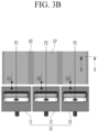
- FIG. 3B illustrates a top plan view of a concept of forming a multi-column coating portion on an electrode substrate by applying an active material slurry to the electrode substrate using a multi-slot die according to one or more embodiments of the present disclosure.
- dies 10 are configured to form a coating portion CP by coating a supplied active material slurry on an electrode substrate ES proceeding while being supported by a backup roll BR via a chamber CB formed between a lower die 101 and an upper die 102.
- FIG. 3C illustrates a cross-sectional view taken along line B-B in FIG. 3B according to one or more embodiments
- FIG. 4 illustrates a partially exploded perspective view of the multi-slot die of FIG. 3B according to one or more embodiments
- FIG. 5 illustrates a partially exploded perspective view of a die control unit and one slot die among the multi-slot dies of FIG. 3B according to one or more embodiments.
- the multi-slot die may include a plurality of dies (10; 11, 12, 13), a plurality of gap adjustment assemblies 20 and a die position adjustment assembly 30.
- the plurality of dies 10 may include first, second, and third dies 11, 12, and 13.
- the plurality of dies 10 may be formed in multiple columns by separating the continuous coating portion CP in the length direction (e.g., the y direction in FIG. 4 ) on one continuously progressed electrode substrate ES using a supplied active material slurry along the width direction (e.g., the x direction in FIG. 4 ) crossing the length direction.
- the first, second, and third dies 11, 12, and 13 may form the coating portion CP in three or more columns.
- the double-sided coating portion CP of the electrode substrate ES has an alignment step AS for alignment in the width direction.
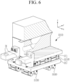
- FIG. 6 illustrates a partially cross-sectional perspective view of a coupled state of one slot die and a gap adjustment assembly as shown in FIG. 5 according to one or more embodiments.
- the gap adjustment assemblies 20 may correspond to the first, second, and third dies 11, 12, and 13, and may be configured to independently adjust first, second, and third gaps G1, G2, and G3 respectively set between the electrode substrate ES and the first, second, and third dies 11, 12, and 13 along the discharge direction (e.g., the y-axis direction) of the die. Since the first, second, and third gaps G1, G2, and G3 may be adjusted by the gap adjustment assembly 20, the coating width and the quality of the rolling level of the coating portion CP may be improved.
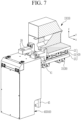
- FIG. 7 illustrates a partially cross-sectional perspective view of a coupled state of a gap adjustment assembly of FIG. 6 and a die control unit according to one or more embodiments
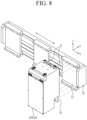
- FIG. 8 illustrates a perspective view of a coupled state of the die control unit, moving member and linear motor of FIG. 7 according to one or more embodiments.
- the die position adjustment assembly 30 may correspond to the gap adjustment assemblies 20, and may be configured to independently adjust first, second, and third die positions P1, P2, and P3 of the first, second, and third dies 11, 12, and 13 in the width direction (e.g., the x-axis direction). Since the first, second, and third die positions P1, P2, and P3 may be adjusted by the die position adjustment assembly 30, the coating portion CP may be aligned on both surfaces of the electrode substrate ES. Accordingly, the die position adjustment assembly 30 may improve the quality of the step AS on both surfaces of the coating portion CP.
- the gap adjustment assemblies 21-23 (20) support the first, second, and third dies 11, 12, and 13, respectively.
- Each of the gap adjustment assemblies 20 may include a die support block 21, a gap guide 22, and a first fixing plate 23 to allow for independently adjusting the first, second, and third gaps G1, G2, and G3 of the first, second, and third dies 11, 12, and 13.
- the die support block 21 may be configured to support the third die 13 on its upper surface and to be moved in the discharge direction (e.g., the y-axis direction).
- the gap guide 22 may be coupled to the die support block 21 to move the die support block 21 in the discharge direction (e.g., the y-axis direction) to adjust the third gap G3 set between the third die 13 supported by the die support block 21 and the electrode substrate ES.
- the first fixing plate 23 supports the gap guide 22.
- the third die 13 is installed on the first fixing plate 23 through the gap adjustment assembly 20, and the third die 13 is moved forward and backward in the discharge direction (e.g., the y-axis direction) by the gap adjustment assembly 20 to adjust the third gap G3.
- the first, second, and third dies 11, 12, and 13 are provided in respective gap adjustment assemblies 20, the first, second, and third gaps G1, G2, and G3 may be independently adjusted.
- the die position adjustment assembly 30 may support a plurality of first fixing plates 23 that support each of the first, second, and third dies 11, 12, and 13, respectively, corresponding to (e.g., aligned with) the gap adjustment assemblies 20.
- the die position adjustment assembly 30 further may further include a plurality of plate support blocks 31, a position guide 32 and a second fixing plate 33.
- the plurality of plate support blocks 31 may be configured to support each of the first fixing plates 23 upward and to move in the width direction (e.g., the x-axis direction).
- the position guide 32 may be coupled to the plate support block 31 and may extend in the width direction (e.g., the x-axis direction) to move the plate support block 31 left and right (on the drawing) in the width direction (e.g., the x-axis direction) to adjust the first, second, and third die positions P1, P2, and P3.
- the second fixing plate 33 corresponds to all of the gap adjustment assemblies 20 and supports the position guide 32.
- a plurality of slot dies 10 may be installed on the second fixing plate 33 through the position guide 32 and the gap adjustment assemblies 20.
- the first, second, and third dies 11, 12, and 13 are moved in the width direction (e.g., the x-axis direction) by the die position adjustment assembly 30 and the gap adjustment assembly 20
- the first, second, and third die positions P1, P2, and P3 of the electrode substrate ES may be adjusted and set in the width direction (e.g., the x-axis direction), and while being moved forward and backward in the discharge direction (e.g., the y-axis direction), the first, second, and third gaps G1, G2, and G3 may be adjusted and set.
- a position of each of the plurality of slot dies 10 with respect to the electrode substrate ES may be individually and independently adjusted in two directions.
- the position of each of the slotdies 10 may be adjusted, for example, in a width direction and in a discharge direction.
- the width direction and the discharge direction may be orthogonal to each other.
- the multi-slot die may further include die control units (40; 401, 402, 403).
- the die control units 40 may be provided respectively corresponding to (e.g., aligned with) aligned with the first, second, and third dies 11, 12, and 13 and may be respectively coupled to the first, second, and third dies 11, 12, and 13.
- the die control units 40 that is, the first, second, and third die control units 401, 402, and 403, respectively may control the first, second, and third gaps G1, G2, and G3 and the first, second, and third die positions P1, P2, and P3 of the first, second, and third dies 11, 12, and 13.
- the third die control unit 403 may include a coupling member 41, a gap adjustment member 42, a lifting plate 43, and a lifting cylinder 44, and may be coupled to the third die 13.
- this is merely one example.
- the coupling member 41 may protrude upward from the third die control unit 403 and may be coupled to a coupling hole 24 provided in the third die 13.
- the gap adjustment member 42 may be configured to adjust the coupling member 41 in the gap adjustment direction (e.g., the y-axis direction). As an example, the gap adjustment member 42 may finely adjust the third gap G3 in units of less than 0.01 mm pitch, less than 0.005 mm pitch or in units of 0.001 mm pitch.
- the lifting plate 43 may include the coupling member 41 and the gap adjustment member 42.
- the lifting cylinder 44 may be coupled to the lifting plate 43 and may be fixed to the side plate 45.
- the lifting cylinder 44 moves up and down while acting as a reaction force against the side plate 45 to insert or withdraw the coupling member 41 provided on the lifting plate 43 into the coupling hole 24.
- the coupling member 41 may move the third die 13 on the gap adjustment assembly 20 through the coupling hole 24. Accordingly, the third gap G3 may be adjusted and set.
- the multi-slot die may further include a base plate 51 and a linear motor 52.
- the base plate 51 supports the second fixing plate 33 installed on its upper surface.
- the linear motor 52 may be provided on a lower side of the base plate 51.
- the side plate 45 may be installed on a moving member 53 of the linear motor 52.
- the moving member 53 may be moved in the width direction (e.g., the x-axis direction). Accordingly, the third die position P3 may be adjusted and set as the third die control unit 403 installed on the moving member 53 using the side plate 45 moves in the width direction (e.g., the x-axis direction).
- FIG. 9 illustrates a flowchart of forming a multi-column coating portion on an electrode substrate by applying an active material slurry to the electrode substrate using a multi-slot die coating method according to one or more embodiments of the present disclosure.
- the multi-slot die coating method of the embodiment includes a first step (ST1), a second step (ST2), a third step (ST3), a fourth step (ST4) and a fifth step (ST5).
- the first step (ST1) data on the loading level, coating width, and double-sided step AS of the coating portion CP to be applied with the active material slurry may be inputted to the continuously supplied electrode substrate ES.
- the double-sided step AS may designate a difference between the extension, e.g. in a width direction, of a coating portion CP arranged on one side of the electrode substrate ES, and a coating portion CP arranged on an opposite side of the electrode substrate ES.
- the input data may be input to the die control unit 40.
- the input data my include density data and vision data.
- the density data may be a loading level, and the vision data may be a coating width, a double-sided step AS and a coating position.
- adjustment factors may be determined.
- the adjustment factors may include a total loading level central value, a hot loading level central value, a double-sided step AS, a coating width, a coating position, and a width direction loading level, of the coating portion CP.
- a total flow rate of the slurry to be supplied may be determined, during coating. That is, in the third step (ST3), the total flow rate of supplying the active material slurry from a pump P to the dies (10; 11, 12, 13) may be determined by controlling the pump P to supply the active material slurry according to the center value of the total loading level. To this end, a three-way valve 3WV installed between the pump P and a manifold 61 may be controlled to return excess flow to a tank T.
- control valves (62; 621, 622, 623) may be proportionally controlled according to the hot loading level center value, so that the active material slurry may be supplied to each die (10; 11, 12, 13), and the coating portion CP may be formed in multiple columns on the electrode substrate ES, respectively.
- the first, second, third gaps G1, G2, and G3 of the dies 10, that is, the first, second, third dies 11, 12, and 13, and the first, second, third die positions P1, P2, and P3 may be adjusted.
- the coating width may be controlled by adjusting the gap adjustment member 42 in the die control units (40; 401, 402, 403), and the coating position and the double-sided step AS may be controlled by adjusting the linear motor 52.
- the positions P1, P2, and P3 of the first, second, and third dies 11, 12, and 13 may be adjusted according to the double-sided step AS, respectively.
- the first, second, and third gaps G1, G2, and G3 of the first, second, and third dies 11, 12, and 13 may be adjusted according to the coating width, coating position, and width direction loading level, respectively.
- new data on the loading level, coating width, coating position and double-sided step AS obtained in the fifth step (ST5) may be compared with the existing data on the inputted loading level, coating width, coating position and double-sided step AS.
- the new data and the existing data may be compared to determine the adjustment factors. According to this determination, the first, second, and third gaps G1, G2, and G3 and the first, second, and third die positions P1, P2, and P3 may be continuously adjusted in the next fifth step ST5. Accordingly, if the coating portion CP is coated in multiple columns with the active material slurry on the electrode substrate ES, the quality of the multi-column coating portion CP may be improved.
- FIG. 10 illustrates a perspective view of a slurry supply system for supplying an active material slurry to the multi-slot die of FIG. 3A , FIG. 3B , and FIG. 4 according to one or more embodiments
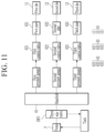
- FIG. 11 illustrates a block diagram of the slurry supply system of FIG. 10 according to one or more embodiments.
- the slurry supply system may be configured to supply an active material slurry to the multi-slot die.
- the slurry supply system may include a manifold 61, a plurality of control valves (62; 621, 622, 623), a plurality of pipes (63; 631, 632, 633) and a plurality of return pipes (64; 641, 642, 643).
- the manifold 61 may supply the active material slurry continuously supplied to the plurality of dies 10 by driving the pump P and the three-way valve 3WV.
- the slurry may be applied to both surfaces of the electrode substrate ES to form the coating area CP.
- the control valves 62 that is, the first, second, and third control valves 621, 622, and 623 may be coupled to the pipes 63 (that is, the first, second, and third pipes 631, 632, and 633) and divided into three from the manifold 61 to independently supply the slurry from the manifold 61 to the first, second, and third dies 11, 12, and 13.
- the first, second, and third pipes 631, 632, and 633 independently couple the first, second, and third control valves 621, 622, and 623 to the first, second, and third dies 11, 12, and 13.
- the first, second, and third control valves 621, 622, and 623 may be formed as proportional control valves.
- the slurry supply system returns surplus or uncoated slurry to the tank T through the three-way valve 3WV installed between the pump P and the manifold 61. That is, the slurry supply system may determine the total flow rate supplied to the manifold 61 and the first, second, and third control valves 621, 622, and 623 by the control of the pump P and the three-way valve 3WV, and control the amount of slurry flowing into the first, second, and third dies 11, 12, and 13 by the opening amount of the first, second, and third control valves 621, 622, and 623.
- the first, second, and third pipes 631, 632, and 633 may be formed as flexible pipes, the first, second, and third gaps G1, G2, and G3 of the first, second, and third dies 11, 12, and 13 may be adjusted by the gap adjustment assemblies 20 and the die position adjustment assembly 30, and the adjustment operation is not disturbed if the first, second, and third die positions P1, P2, and P3 are adjusted.
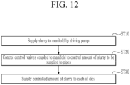
- FIG. 12 is a flowchart of supplying an active material slurry to a multi-slot die using a slurry supply method according to one or more embodiments of the present disclosure.
- the method of supplying the slurry according to the embodiment includes a first step (ST10), a second step (ST20), and a third step (ST30).
- an active material slurry to be applied to the electrode substrate ES continuously supplied by driving the pump P may be supplied to the manifold 61.
- the amount of slurry to be supplied to the plurality of pipes (63; 631, 632, 633) may be controlled by controlling the plurality of control valves (62; 621, 622, 623) coupled to the manifold 61.
- a controlled amount of slurry may be supplied to each of the dies (10; 11, 12, 13) coupled to the pipes (63; 631, 632, 633).
- control valves (62; 621, 622, 623) may be proportionally controlled. That is, the control valves (62; 621, 622, 623) may control the amount of slurry supplied by controlling the ratio (%) of the opening amount to the full opening amount (100 %).
- the active material slurry passing through in the second and third steps (ST20 and ST30) may be applied to the electrode substrate ES through the dies (10; 11, 12, 13) to form the coating portion CP.
- the control valves (62; 621, 622, 623) may control the quality of the loading level, which is density data of the coating portion CP.
- the present disclosure provides a multi-slot die that coats an electrode substrate of a rechargeable battery with an active material slurry in multiple columns and independently controls quality of a multi-column coating portion.
- the present disclosure also provides a coating method that coats an active material slurry on an electrode substrate in multiple columns using the multi-slot die and may independently control quality of a multi-row coating portion.
- the present disclosure also provides a slurry supply system that supplies an active material slurry to an electrode substrate of a rechargeable battery in multiple columns.
- the present disclosure further provides a slurry supply method that supplies an active material slurry to an electrode substrate in multiple columns using the slurry supply system.
- the multi-slot die and the multi-slot die coating method of the embodiment(s) include a plurality of dies, gap adjustment assemblies, and die position adjustment assemblies to independently control gaps and independently control die positions, thereby improving quality of a multi-column coating portion if coating an electrode substrate with an active material slurry in multiple columns.
- the slurry supply system and the slurry supply method may determine a total amount of slurry to be supplied by a pump and a three-way valve, and may supply the slurry by proportionally controlling control valves, thereby improving quality of a loading level.
Landscapes
- Engineering & Computer Science (AREA)
- Manufacturing & Machinery (AREA)
- Chemical & Material Sciences (AREA)
- Chemical Kinetics & Catalysis (AREA)
- Electrochemistry (AREA)
- General Chemical & Material Sciences (AREA)
- Physics & Mathematics (AREA)
- Fluid Mechanics (AREA)
- Battery Electrode And Active Subsutance (AREA)
- Coating Apparatus (AREA)
- Application Of Or Painting With Fluid Materials (AREA)
Abstract
Description
- This application claims priority to and the benefit of
Korean Patent Application No. 10-2023-0109136 filed in the Korean Intellectual Property Office on August 21, 2023 - Embodiments relate to a multi-slot die that coats an active material slurry on an electrode substrate of a rechargeable battery, and relate to a coating method using the same, a slurry supply system, and a slurry supply method using the same.
- A rechargeable battery is a battery that is repeatedly charged and discharged, unlike a primary battery. A small capacity rechargeable battery is used in a small portable electronic device such as a mobile phone, a notebook computer, and a camcorder, while a large capacity rechargeable battery may be used as a power source for driving a motor of a hybrid vehicle and an electric vehicle.
- For example, the rechargeable battery includes an electrode assembly for the charge and discharging, a pouch accommodating the electrode assembly, and an electrode terminal that electrically connects the electrode assembly and draws it out of the pouch. The electrode assembly includes a winding type in which a negative electrode plate and a positive electrode plate are wound with a separator interposed therebetween, and a stacking type in which a negative electrode plate and a positive electrode plate are stacked with a separator interposed therebetween.
- An electrode plate process of manufacturing an electrode plate includes a mixing step of mixing an active material slurry, a coating step of coating a coating portion of the active material slurry to an electrode substrate in multiple columns, a pressing step of compressing the coating portion of the active material slurry, and a slitting step of cutting the electrode substrate according to the columns of the coating portion.
- The electrode plate process equipment is a slot die coating an active material slurry, and allows to be coated with a positive or negative active material slurry mixed on an electrode substrate of Al or Cu at a predetermined width and thickness and to be dried to maintain a predetermined loading level (mg/cm2).
- The multi-column coating slot die may cause a defect in the press stage equipment due to a defective loading level, and may cause a defect in the winding equipment due to a step in the coating width at both coating portions of the electrode substrate.
- During multi-column coating, independent control of each column among the multiple columns of coating portions is not possible in a single slot die. That is, if viewed from the width direction of the slot die with reference to
FIG. 1 , the supply flow rate of the active material slurry is high at 1.0 m/s at the center and low at 0.994 m/s at both ends. As a result, the deviation of the loading level in the width direction of the slot die becomes large to 0.006 m/s, and the step on both sides of the coating part becomes large. - Embodiments include a multi-slot die. The multi-slot die includes a plurality of dies that form a continuous coating portion along a length direction on an electrode substrate that continuously proceeds in multiple columns to be spaced apart from each other along a width direction intersecting the length direction, using a supplied active material slurry, a plurality of gap adjustment assemblies that are provided corresponding to each of the dies and independently adjust gaps set between each of the dies and the electrode substrate along a discharge direction of each of the dies and a die position adjustment assembly that is provided corresponding to the gap adjustment assemblies and independently adjusts positions of the dies with respect to the width direction.
- Each of the plurality of gap adjustment assemblies may include a die support block that supports each of the dies and moves in the discharge direction, a gap guide that is coupled to the die support block and moves the die support block in the discharge direction to adjust a respective one of the gaps and a first fixing plate supporting the gap guide.
- The die position adjustment assembly may include a plurality of plate support blocks supporting the first fixing plate corresponding to each of the gap adjustment assemblies and moving in the width direction, a position guide coupled to the plate support blocks to adjust a die position by moving each of the plate support blocks in the width direction and a second fixing plate supporting the position guide.
- The multi-slot die may further include a plurality of die control units coupled to each of the dies to control the respective one of the gaps and the die position of each of the dies.
- Each of the die control units may include a coupling member coupled to a coupling hole provided in each of the dies, a gap adjustment member adjusting the coupling member in a gap adjustment direction, a lifting plate including the coupling member and the gap adjustment member and a lifting cylinder coupled to the lifting plate to be fixed to a side plate.
- The multi-slot die may further include a base plate supporting the second fixing plate, and a linear motor provided on a lower side of the base plate, wherein the side plate may be installed on a moving member of the linear motor.
- Embodiments include a multi-slot die coating method. The method includes a first step of inputting data on a loading level, a coating width, a double-sided step, and a coating position of a coating portion to be applied with an active material to a continuously supplied electrode substrate, a second step of determining adjustment factors of a total loading level center value, a hot loading level center value, a double-sided step, a coating width, a coating position, and a width direction loading level, a third step of determining a total amount of active material slurry to be supplied by controlling a pump that supplies an active material slurry and a three-way valve installed between the pump and a manifold according to the total loading level center value, during coating, a fourth step of proportionally controlling control valves according to the hot loading level central value to control a flow rate for each individual die to supply slurry to each die to form multiple columns of coating portions on the electrode substrate, during coating, and a fifth step of adjusting gaps and positions of the dies according to the double-sided step, the coating width, the coating position, and the width direction loading level.
- In the fifth step, a position of each of the dies may be adjusted according to the double-sided step.
- In the fifth step, a gap of each of the dies may be adjusted according to the coating width, the coating position and the width direction loading level.
- In the first step, new data on the loading level, coating width, coating position and double-sided step obtained in the fifth step may be compared with existing data on the loading level, coating width, coating position and double-sided step that are previously inputted.
- In the second step, by comparing the new data and the existing data, adjustment factors may be determined.
- Embodiments include a slurry supply system. The system includes a manifold that supplies an active material slurry to be applied to an electrode substrate continuously supplied by driving a pump and a three-way valve to a plurality of dies, a plurality of control valves coupled to the manifold, a plurality of pipes respectively coupling the control valves to the dies and a tank coupling the three-way valve to the pump.
- The control valves may be proportional control valves. The slurry supply system may further include a pressure gauge disposed between the manifold and the proportional control valve to detect a pressure inside the manifold, wherein the control valves may be proportionally controlled according to the pressure of the pressure gauge to control a return amount of the slurry using the return pipe.
- The pipes may be flexible pipes.
- Embodiments include a slurry supply method. The method includes a first step of supplying an active material slurry to be applied to an electrode substrate continuously supplied by driving a pump and a three-way valve to a manifold, a second step of controlling an amount of slurry to be supplied to a plurality of pipes by controlling a plurality of control valves coupled to the manifold and a third step of supplying a controlled amount of slurry to each of a plurality of dies coupled to the pipes.
- In the second step, the control valves may be proportionally controlled.
- Features will become apparent to those of ordinary skill in the art by describing in detail exemplary embodiments with reference to the attached drawings, in which:
-
FIG. 1 illustrates a graph of a flow rate distribution of slurry along a width direction of a slot die (electrode substrate) according to the prior art; -
FIG. 2 illustrates a graph of a flow rate distribution of slurry along a width direction of a multi-slot die (electrode substrate) according to one or more embodiments of the present disclosure; -
FIG. 3A illustrates a cross-sectional view of applying an active material slurry to an electrode substrate using a multi-slot die according to one or more embodiments of the present disclosure; -
FIG. 3B illustrates a top plan view of a concept of forming a multi-column coating portion on an electrode substrate by applying an active material slurry to the electrode substrate using a multi-slot die according to one or more embodiments of the present disclosure; -
FIG. 3C illustrates a cross-sectional view taken along line B-B inFIG. 3B according to one or more embodiments of the present disclosure; -
FIG. 4 illustrates a partially exploded perspective view of the multi-slot die ofFIG. 3 according to one or more embodiments; -
FIG. 5 illustrates a partially exploded perspective view of a die control unit and one slot die among the multi-slot dies ofFIG. 3 according to one or more embodiments; -
FIG. 6 illustrates a partially cross-sectional perspective view of a coupled state of one slot die and a gap adjustment assembly as shown inFIG. 5 according to one or more embodiments; -
FIG. 7 illustrates a partially cross-sectional perspective view of a coupled state of a gap adjustment assembly ofFIG. 6 and a die control unit according to one or more embodiments; -
FIG. 8 illustrates a perspective view of a coupled state of the die control unit, moving member, and linear motor ofFIG. 7 according to one or more embodiments; -
FIG. 9 illustrates a flowchart of forming a multi-column coating portion on an electrode substrate by applying an active material slurry to the electrode substrate using a multi-slot die coating method according to one or more embodiments of the present disclosure; -
FIG. 10 illustrates a perspective view of a slurry supply system for supplying an active material slurry to the multi-slot die ofFIG. 3A ,FIG. 3B , andFIG. 4 according to one or more embodiments; -
FIG. 11 illustrates a block diagram of the slurry supply system ofFIG. 10 according to one or more embodiments; and -
FIG. 12 illustrates a flowchart of supplying an active material slurry to a multi-slot die using a slurry supply method according to one or more embodiments of the present disclosure. - Example embodiments will now be described more fully hereinafter with reference to the accompanying drawings; however, they may be embodied in different forms and should not be construed as limited to the embodiments set forth herein. Rather, these embodiments are provided so that this disclosure will be thorough and complete, and will fully convey exemplary implementations to those of ordinary skill in the art.
- In the drawing figures, the dimensions of layers and regions may be exaggerated for clarity of illustration. It will also be understood that if a layer or element is referred to as being "on" another layer or substrate, it can be directly on the other layer or substrate, or intervening layers may also be present. Further, it will be understood that if a layer is referred to as being "under" another layer, it can be directly under, and one or more intervening layers may also be present. In addition, it will also be understood that if a layer is referred to as being "between" two layers, it can be the only layer between the two layers, or one or more intervening layers may also be present. Like reference numerals refer to like elements throughout.
-
FIG. 2 is a graph of a flow rate distribution of slurry according to a width direction of a multi-slot die (electrode substrate) according to one or more embodiments of the present disclosure. Referring toFIG. 2 , if viewed from a width direction of the multi-slot die, a supply flow rate of an active material slurry may be 0.9945 m/s at the center and may be 0.994 m/s at both ends. Accordingly, the deviation of the slurry flow rate in the width direction of the slot die may be 0.0005 m/s. - Comparing
FIG. 1 andFIG. 2 , the flow rate at both ends in the width direction of the slot die may be the same as 0.994 m/s in the embodiment compared to 0.994 m/s in the prior art. In this case, the embodiment may be a single slot die of a multi-slot die, while the prior art is a single slot die. - At the center of the width direction of the multi-slot die, the flow rate of the embodiment is 0.9945 m/s, which is slightly lower than the flow rate of 1.0 m/s of the prior art. In terms of the deviation of the loading level in the width direction of the slot die, 0.0005 m/s in the embodiment is much smaller than 0.006 m/s in the prior art.
- Therefore, compared to the prior art, the present embodiment may have higher quality in terms of the double-sided step (AS), coating width, and width loading level of the active material coating portion (CP) formed on both sides of the electrode substrate (ES). Hereinafter, an embodiment implementing this will be described in detail.
-
FIG. 3A illustrates a cross-sectional view of applying an active material slurry to an electrode substrate using a multi-slot die according to one or more embodiments of the present disclosure, andFIG. 3B illustrates a top plan view of a concept of forming a multi-column coating portion on an electrode substrate by applying an active material slurry to the electrode substrate using a multi-slot die according to one or more embodiments of the present disclosure. - Referring to
FIG. 3A andFIG. 3B , dies 10 are configured to form a coating portion CP by coating a supplied active material slurry on an electrode substrate ES proceeding while being supported by a backup roll BR via a chamber CB formed between alower die 101 and anupper die 102. -
FIG. 3C illustrates a cross-sectional view taken along line B-B inFIG. 3B according to one or more embodiments,FIG. 4 illustrates a partially exploded perspective view of the multi-slot die ofFIG. 3B according to one or more embodiments, andFIG. 5 illustrates a partially exploded perspective view of a die control unit and one slot die among the multi-slot dies ofFIG. 3B according to one or more embodiments. - Referring to
FIG. 3A to 5 , the multi-slot die may include a plurality of dies (10; 11, 12, 13), a plurality ofgap adjustment assemblies 20 and a dieposition adjustment assembly 30. - As an example, the plurality of dies 10 may include first, second, and third dies 11, 12, and 13. The plurality of dies 10 may be formed in multiple columns by separating the continuous coating portion CP in the length direction (e.g., the y direction in
FIG. 4 ) on one continuously progressed electrode substrate ES using a supplied active material slurry along the width direction (e.g., the x direction inFIG. 4 ) crossing the length direction. The first, second, and third dies 11, 12, and 13 may form the coating portion CP in three or more columns. The double-sided coating portion CP of the electrode substrate ES has an alignment step AS for alignment in the width direction. -
FIG. 6 illustrates a partially cross-sectional perspective view of a coupled state of one slot die and a gap adjustment assembly as shown inFIG. 5 according to one or more embodiments. Referring toFIG. 4 to FIG. 6 , thegap adjustment assemblies 20 may correspond to the first, second, and third dies 11, 12, and 13, and may be configured to independently adjust first, second, and third gaps G1, G2, and G3 respectively set between the electrode substrate ES and the first, second, and third dies 11, 12, and 13 along the discharge direction (e.g., the y-axis direction) of the die. Since the first, second, and third gaps G1, G2, and G3 may be adjusted by thegap adjustment assembly 20, the coating width and the quality of the rolling level of the coating portion CP may be improved. -
FIG. 7 illustrates a partially cross-sectional perspective view of a coupled state of a gap adjustment assembly ofFIG. 6 and a die control unit according to one or more embodiments, andFIG. 8 illustrates a perspective view of a coupled state of the die control unit, moving member and linear motor ofFIG. 7 according to one or more embodiments. - Referring to
FIG. 4 to FIG. 8 , the dieposition adjustment assembly 30 may correspond to thegap adjustment assemblies 20, and may be configured to independently adjust first, second, and third die positions P1, P2, and P3 of the first, second, and third dies 11, 12, and 13 in the width direction (e.g., the x-axis direction). Since the first, second, and third die positions P1, P2, and P3 may be adjusted by the dieposition adjustment assembly 30, the coating portion CP may be aligned on both surfaces of the electrode substrate ES. Accordingly, the dieposition adjustment assembly 30 may improve the quality of the step AS on both surfaces of the coating portion CP. - Referring back to
FIG. 3A to FIG. 6 , the gap adjustment assemblies 21-23 (20) support the first, second, and third dies 11, 12, and 13, respectively. Each of thegap adjustment assemblies 20 may include adie support block 21, agap guide 22, and afirst fixing plate 23 to allow for independently adjusting the first, second, and third gaps G1, G2, and G3 of the first, second, and third dies 11, 12, and 13. - Taking the
third die 13 as an example, thedie support block 21 may be configured to support thethird die 13 on its upper surface and to be moved in the discharge direction (e.g., the y-axis direction). Thegap guide 22 may be coupled to thedie support block 21 to move thedie support block 21 in the discharge direction (e.g., the y-axis direction) to adjust the third gap G3 set between thethird die 13 supported by thedie support block 21 and the electrode substrate ES. Thefirst fixing plate 23 supports thegap guide 22. - Therefore, the
third die 13 is installed on thefirst fixing plate 23 through thegap adjustment assembly 20, and thethird die 13 is moved forward and backward in the discharge direction (e.g., the y-axis direction) by thegap adjustment assembly 20 to adjust the third gap G3. In this way, since the first, second, and third dies 11, 12, and 13 are provided in respectivegap adjustment assemblies 20, the first, second, and third gaps G1, G2, and G3 may be independently adjusted. - Referring to
FIG. 10 , the dieposition adjustment assembly 30 may support a plurality offirst fixing plates 23 that support each of the first, second, and third dies 11, 12, and 13, respectively, corresponding to (e.g., aligned with) thegap adjustment assemblies 20. As an example, the dieposition adjustment assembly 30 further may further include a plurality of plate support blocks 31, aposition guide 32 and asecond fixing plate 33. - The plurality of plate support blocks 31 may be configured to support each of the
first fixing plates 23 upward and to move in the width direction (e.g., the x-axis direction). The position guide 32 may be coupled to theplate support block 31 and may extend in the width direction (e.g., the x-axis direction) to move theplate support block 31 left and right (on the drawing) in the width direction (e.g., the x-axis direction) to adjust the first, second, and third die positions P1, P2, and P3. Thesecond fixing plate 33 corresponds to all of thegap adjustment assemblies 20 and supports theposition guide 32. - Accordingly, a plurality of slot dies 10 may be installed on the
second fixing plate 33 through theposition guide 32 and thegap adjustment assemblies 20. As the first, second, and third dies 11, 12, and 13 are moved in the width direction (e.g., the x-axis direction) by the dieposition adjustment assembly 30 and thegap adjustment assembly 20, the first, second, and third die positions P1, P2, and P3 of the electrode substrate ES may be adjusted and set in the width direction (e.g., the x-axis direction), and while being moved forward and backward in the discharge direction (e.g., the y-axis direction), the first, second, and third gaps G1, G2, and G3 may be adjusted and set.In other words, a position of each of the plurality of slot dies 10 with respect to the electrode substrate ES may be individually and independently adjusted in two directions. The position of each of theslotdies 10 may be adjusted, for example, in a width direction and in a discharge direction. The width direction and the discharge direction may be orthogonal to each other. - Referring back to
FIG. 4 to FIG. 8 , the multi-slot die according to one or more embodiments may further include die control units (40; 401, 402, 403). Thedie control units 40 may be provided respectively corresponding to (e.g., aligned with) aligned with the first, second, and third dies 11, 12, and 13 and may be respectively coupled to the first, second, and third dies 11, 12, and 13. - Accordingly, the
die control units 40, that is, the first, second, and thirddie control units - For example, referring to
FIG. 7 , the thirddie control unit 403 may include acoupling member 41, agap adjustment member 42, a liftingplate 43, and alifting cylinder 44, and may be coupled to thethird die 13. However, this is merely one example. - The
coupling member 41 may protrude upward from the thirddie control unit 403 and may be coupled to acoupling hole 24 provided in thethird die 13. Thegap adjustment member 42 may be configured to adjust thecoupling member 41 in the gap adjustment direction (e.g., the y-axis direction). As an example, thegap adjustment member 42 may finely adjust the third gap G3 in units of less than 0.01 mm pitch, less than 0.005 mm pitch or in units of 0.001 mm pitch. - The lifting
plate 43 may include thecoupling member 41 and thegap adjustment member 42. The liftingcylinder 44 may be coupled to the liftingplate 43 and may be fixed to theside plate 45. The liftingcylinder 44 moves up and down while acting as a reaction force against theside plate 45 to insert or withdraw thecoupling member 41 provided on the liftingplate 43 into thecoupling hole 24. - As the
gap adjustment member 42 is adjusted while thecoupling member 41 is inserted into thecoupling hole 24, thecoupling member 41 may move thethird die 13 on thegap adjustment assembly 20 through thecoupling hole 24. Accordingly, the third gap G3 may be adjusted and set. - In one or more embodiments, the multi-slot die may further include a
base plate 51 and alinear motor 52. Thebase plate 51 supports thesecond fixing plate 33 installed on its upper surface. Thelinear motor 52 may be provided on a lower side of thebase plate 51. Theside plate 45 may be installed on a movingmember 53 of thelinear motor 52. - As the
linear motor 52 is driven, the movingmember 53 may be moved in the width direction (e.g., the x-axis direction). Accordingly, the third die position P3 may be adjusted and set as the thirddie control unit 403 installed on the movingmember 53 using theside plate 45 moves in the width direction (e.g., the x-axis direction). -
FIG. 9 illustrates a flowchart of forming a multi-column coating portion on an electrode substrate by applying an active material slurry to the electrode substrate using a multi-slot die coating method according to one or more embodiments of the present disclosure. Referring toFIG. 9 , the multi-slot die coating method of the embodiment includes a first step (ST1), a second step (ST2), a third step (ST3), a fourth step (ST4) and a fifth step (ST5). - In the first step (ST1), data on the loading level, coating width, and double-sided step AS of the coating portion CP to be applied with the active material slurry may be inputted to the continuously supplied electrode substrate ES. The double-sided step AS may designate a difference between the extension, e.g. in a width direction, of a coating portion CP arranged on one side of the electrode substrate ES, and a coating portion CP arranged on an opposite side of the electrode substrate ES. The input data may be input to the
die control unit 40. The input data my include density data and vision data. The density data may be a loading level, and the vision data may be a coating width, a double-sided step AS and a coating position. - In the second step (ST2), adjustment factors may be determined. The adjustment factors may include a total loading level central value, a hot loading level central value, a double-sided step AS, a coating width, a coating position, and a width direction loading level, of the coating portion CP.
- In the third step (ST3), a total flow rate of the slurry to be supplied may be determined, during coating. That is, in the third step (ST3), the total flow rate of supplying the active material slurry from a pump P to the dies (10; 11, 12, 13) may be determined by controlling the pump P to supply the active material slurry according to the center value of the total loading level. To this end, a three-way valve 3WV installed between the pump P and a manifold 61 may be controlled to return excess flow to a tank T.
- In the fourth step (ST4), the flow rate of the active material slurry may be controlled and supplied for each individual die during coating. That is, in the fourth step (ST4), control valves (62; 621, 622, 623) may be proportionally controlled according to the hot loading level center value, so that the active material slurry may be supplied to each die (10; 11, 12, 13), and the coating portion CP may be formed in multiple columns on the electrode substrate ES, respectively.
- In the fifth step (ST5), the first, second, third gaps G1, G2, and G3 of the dies 10, that is, the first, second, third dies 11, 12, and 13, and the first, second, third die positions P1, P2, and P3 may be adjusted. In the fifth step (ST5), the coating width may be controlled by adjusting the
gap adjustment member 42 in the die control units (40; 401, 402, 403), and the coating position and the double-sided step AS may be controlled by adjusting thelinear motor 52. - Further, in the fifth step ST5, the positions P1, P2, and P3 of the first, second, and third dies 11, 12, and 13 may be adjusted according to the double-sided step AS, respectively. In addition, in the fifth step (ST5), the first, second, and third gaps G1, G2, and G3 of the first, second, and third dies 11, 12, and 13 may be adjusted according to the coating width, coating position, and width direction loading level, respectively.
- In addition, in the first step (ST1), new data on the loading level, coating width, coating position and double-sided step AS obtained in the fifth step (ST5) may be compared with the existing data on the inputted loading level, coating width, coating position and double-sided step AS.
- In the second step (ST2), the new data and the existing data may be compared to determine the adjustment factors. According to this determination, the first, second, and third gaps G1, G2, and G3 and the first, second, and third die positions P1, P2, and P3 may be continuously adjusted in the next fifth step ST5. Accordingly, if the coating portion CP is coated in multiple columns with the active material slurry on the electrode substrate ES, the quality of the multi-column coating portion CP may be improved.
-
FIG. 10 illustrates a perspective view of a slurry supply system for supplying an active material slurry to the multi-slot die ofFIG. 3A ,FIG. 3B , andFIG. 4 according to one or more embodiments, andFIG. 11 illustrates a block diagram of the slurry supply system ofFIG. 10 according to one or more embodiments. - Referring to
FIG. 10 andFIG. 11 , the slurry supply system may be configured to supply an active material slurry to the multi-slot die. - As an example, the slurry supply system may include a manifold 61, a plurality of control valves (62; 621, 622, 623), a plurality of pipes (63; 631, 632, 633) and a plurality of return pipes (64; 641, 642, 643). The manifold 61 may supply the active material slurry continuously supplied to the plurality of dies 10 by driving the pump P and the three-way valve 3WV. The slurry may be applied to both surfaces of the electrode substrate ES to form the coating area CP.
- The control valves 62, that is, the first, second, and
third control valves third pipes - The first, second, and
third pipes third control valves third control valves - The slurry supply system returns surplus or uncoated slurry to the tank T through the three-way valve 3WV installed between the pump P and the manifold 61. That is, the slurry supply system may determine the total flow rate supplied to the manifold 61 and the first, second, and
third control valves third control valves - In some embodiments, the first, second, and
third pipes gap adjustment assemblies 20 and the dieposition adjustment assembly 30, and the adjustment operation is not disturbed if the first, second, and third die positions P1, P2, and P3 are adjusted. -
FIG. 12 is a flowchart of supplying an active material slurry to a multi-slot die using a slurry supply method according to one or more embodiments of the present disclosure. Referring toFIG. 12 , the method of supplying the slurry according to the embodiment includes a first step (ST10), a second step (ST20), and a third step (ST30). - In the first step (ST10), an active material slurry to be applied to the electrode substrate ES continuously supplied by driving the pump P may be supplied to the
manifold 61. In the second step (ST20), the amount of slurry to be supplied to the plurality of pipes (63; 631, 632, 633) may be controlled by controlling the plurality of control valves (62; 621, 622, 623) coupled to themanifold 61. In the third step (ST30), a controlled amount of slurry may be supplied to each of the dies (10; 11, 12, 13) coupled to the pipes (63; 631, 632, 633). - In the second step ((ST20), the control valves (62; 621, 622, 623) may be proportionally controlled. That is, the control valves (62; 621, 622, 623) may control the amount of slurry supplied by controlling the ratio (%) of the opening amount to the full opening amount (100 %).
- The active material slurry passing through in the second and third steps (ST20 and ST30) may be applied to the electrode substrate ES through the dies (10; 11, 12, 13) to form the coating portion CP. In this case, the control valves (62; 621, 622, 623) may control the quality of the loading level, which is density data of the coating portion CP.
- The present disclosure provides a multi-slot die that coats an electrode substrate of a rechargeable battery with an active material slurry in multiple columns and independently controls quality of a multi-column coating portion. The present disclosure also provides a coating method that coats an active material slurry on an electrode substrate in multiple columns using the multi-slot die and may independently control quality of a multi-row coating portion.
- The present disclosure also provides a slurry supply system that supplies an active material slurry to an electrode substrate of a rechargeable battery in multiple columns. The present disclosure further provides a slurry supply method that supplies an active material slurry to an electrode substrate in multiple columns using the slurry supply system.
- As described above, the multi-slot die and the multi-slot die coating method of the embodiment(s) include a plurality of dies, gap adjustment assemblies, and die position adjustment assemblies to independently control gaps and independently control die positions, thereby improving quality of a multi-column coating portion if coating an electrode substrate with an active material slurry in multiple columns.
- In addition, the slurry supply system and the slurry supply method according to one or more embodiments may determine a total amount of slurry to be supplied by a pump and a three-way valve, and may supply the slurry by proportionally controlling control valves, thereby improving quality of a loading level.
- While this disclosure has been described in connection with what is presently considered to be practical embodiments, it is to be understood that the disclosure is not limited to the disclosed embodiments, but, on the contrary, is intended to cover various modifications and equivalent arrangements included within the scope of the appended claims.
- Example embodiments have been disclosed herein, and although specific terms are employed, they are used and are to be interpreted in a generic and descriptive sense only and not for purpose of limitation. In some instances, as would be apparent to one of ordinary skill in the art as of the filing of the present application, features, characteristics, and/or elements described in connection with a particular embodiment may be used singly or in combination with features, characteristics, and/or elements described in connection with other embodiments unless otherwise specifically indicated. Accordingly, it will be understood by those of skill in the art that various changes in form and details may be made without departing from the spirit and scope of the present invention as set forth in the following claims.
<Description of Symbols> 10: die 11, 12, 13: first, second, third dies 20: gap adjustment assembly 21: die support block 22: gap guide 23: first fixing plate 24: coupling hole 30: die position adjustment assembly 31: plate support block 32: position guide 33: second fixing plate 40: die control unit 41: coupling member 42: gap adjustment member 43: lifting plate 44: lifting cylinder 45: side plate 51: base plate 52: linear motor 53: moving member 61: manifold 62: control valve 63: pipe 64: return pipe 101: lower die 102: upper die 401, 402, 403: first, second, third die control units 621, 622, 623: first, second, third control valves 631, 632, 633: first, second, third pipes 641, 642, 643: first, second, third return pipes CP: coating portion G1, G2, G3: first, second, third gaps ES: electrode substrate P: pump BR: backup roll CB: chamber P1, P2, P3: first, second, third die positions
Claims (15)
- A multi-slot die (10) , comprising:a plurality of dies (11, 12, 13) that form a continuous coating portion, CP, along a length direction on an electrode substrate, ES, that continuously proceeds in multiple columns to be spaced apart from each other along a width direction intersecting the length direction, using a supplied active material slurry;a plurality of gap adjustment assemblies (20) that are provided corresponding to each of the dies (11, 12, 13) and independently adjust gaps (G1, G2, G3) set between each of the dies (11, 12, 13) and the electrode substrate ES along a discharge direction of each of the dies (11, 12, 13); anda die position adjustment assembly (30) that is provided corresponding to the gap adjustment assemblies (20) and independently adjusts positions of the dies (11, 12, 13) with respect to the width direction.
- The multi-slot die (10) as claimed in claim 1, wherein each of the plurality of gap adjustment assemblies (20) includesa die support block (21) that supports each of the dies (11, 12, 13) and moves in the discharge direction,a gap guide (22) that is coupled to the die support block (21) and moves the die support block (21) in the discharge direction to adjust a respective one of the gaps (G1, G2, G3), anda first fixing plate (23) supporting the gap guide (22).
- The multi-slot die (10) as claimed in claim 1 or in claim 2, wherein the die position adjustment assembly (30) includesa plurality of plate support blocks (31) supporting the first fixing plate (23) corresponding to each of the gap adjustment assemblies (20) and moving in the width direction,a position guide (32) coupled to the plate support blocks (31) to adjust a die position by moving each of the plate support blocks (31) in the width direction, anda second fixing plate (33) supporting the position guide (32).
- The multi-slot die (10) as claimed in one of claims 1 through 3, further comprising a plurality of die control units (40) coupled to each of the dies (11, 12, 13) to control the respective one of the gaps (G1, G2, G3) and the die position of each of the dies (11, 12, 13).
- The multi-slot die (10) as claimed in one of claims 1 through 4, wherein each of the die control units (40) includesa coupling member (41) coupled to a coupling hole (24) provided in each of the dies (G1, G2, G3),a gap adjustment member (42) adjusting the coupling member (41) in a gap adjustment direction,a lifting plate (43) including the coupling member (41) and the gap adjustment member (42), anda lifting cylinder (44) coupled to the lifting plate (43) to be fixed to a side plate (45).
- The multi-slot die (10) as claimed in one of claims 3 through claim 5, further comprising:a base plate (51) supporting the second fixing plate (33), anda linear motor (52) provided on a lower side of the base plate (51),wherein the side plate (45) is installed on a moving member (53) of the linear motor (52).
- A multi-slot die (10) coating method, comprising:a first step of inputting data on a loading level, a coating width, a double-sided step, and a coating position of a coating portion to be applied with an active material to a continuously supplied electrode substrate, ES;a second step of determining adjustment factors of a total loading level center value, a hot loading level center value, a double-sided step, a coating width, a coating position, and a width direction loading level;a third step of determining a total amount of active material slurry to be supplied by controlling a pump that supplies an active material slurry and a three-way valve installed between the pump and a manifold (61) according to the total loading level center value, during coating;a fourth step of proportionally controlling control valves (62) according to the hot loading level central value to control a flow rate for each individual die (11, 12, 13) to supply slurry to each die (11, 12, 13) to form multiple columns of coating portions on the electrode substrate ES, during coating; anda fifth step of adjusting gaps (G1, G2, G3) and positions of the dies (11, 12, 13) according to the double-sided step, the coating width, the coating position, and the width direction loading level.
- The multi-slot die (10) coating method as claimed in claim 7, wherein in the fifth step, a position of each of the dies (11, 12, 13) is adjusted according to the double-sided step and/or a gap of each of the dies (11, 12, 13) is adjusted according to the coating width, the coating position and the width direction loading level.
- The multi-slot die (10) coating method as claimed in claim 7 or in claim 8, wherein in the first step, new data on the loading level, coating width, coating position and double-sided step obtained in the fifth step are compared with existing data on the loading level, coating width, coating position and double-sided step that are previously inputted.
- The multi-slot die (10) coating method as claimed in one of claims 7 through 9, wherein in the second step, by comparing the new data and the existing data, adjustment factors are determined.
- A slurry supply system, comprising:a manifold (61) that supplies an active material slurry to be applied to an electrode substrate, ES, continuously supplied by driving a pump and a three-way valve to a plurality of dies (11, 12, 13);a plurality of control valves (62) coupled to the manifold;a plurality of pipes (63) respectively coupling the control valves (62) to the dies (11, 12, 13); anda tank coupling the three-way valve to the pump.
- The slurry supply system as claimed in claim 11, wherein the control valves (62) are proportional control valves.
- The slurry supply system as claimed in claim 11 or in claim 12, wherein the pipes (63) are flexible pipes.
- A slurry supply method comprising:a first step of supplying an active material slurry to be applied to an electrode substrate, ES, continuously supplied by driving a pump and a three-way valve to a manifold (61);a second step of controlling an amount of slurry to be supplied to a plurality of pipes (63) by controlling a plurality of control valves (62) coupled to the manifold (61); anda third step of supplying a controlled amount of slurry to each of a plurality of dies (11, 12, 13) coupled to the pipes (63).
- The slurry supply method as claimed in claim 15, wherein
in the second step, the control valves (62) are proportionally controlled.
Applications Claiming Priority (1)
| Application Number | Priority Date | Filing Date | Title |
|---|---|---|---|
| KR1020230109136A KR20250028028A (en) | 2023-08-21 | 2023-08-21 | multi slot die, coating method using the same, slurry supply system, and slurry supply method using the same |
Publications (2)
| Publication Number | Publication Date |
|---|---|
| EP4552750A2 true EP4552750A2 (en) | 2025-05-14 |
| EP4552750A3 EP4552750A3 (en) | 2025-07-09 |
Family
ID=92408880
Family Applications (1)
| Application Number | Title | Priority Date | Filing Date |
|---|---|---|---|
| EP24194253.1A Pending EP4552750A3 (en) | 2023-08-21 | 2024-08-13 | Multi-slot die, coating method using the same, slurry supply system, and slurry supply method using the same |
Country Status (5)
| Country | Link |
|---|---|
| US (1) | US20250065358A1 (en) |
| EP (1) | EP4552750A3 (en) |
| JP (1) | JP7793672B2 (en) |
| KR (1) | KR20250028028A (en) |
| CN (1) | CN119489011A (en) |
Family Cites Families (7)
| Publication number | Priority date | Publication date | Assignee | Title |
|---|---|---|---|---|
| DE10216972A1 (en) * | 2002-04-16 | 2003-10-30 | Nordson Corp Westlake | Device for delivery of fluid to movable base material has application head with device to adjust it from working position into service position in which head is horizontally spaced away from material's path of movement |
| KR101333395B1 (en) * | 2009-03-30 | 2013-11-28 | 도요타지도샤가부시키가이샤 | Coating die and coating apparatus comprising the same |
| JP2014065021A (en) * | 2012-09-27 | 2014-04-17 | Gs Yuasa Corp | Coating apparatus |
| CN104808446B (en) * | 2015-05-07 | 2021-02-02 | 合肥京东方光电科技有限公司 | Coating machine |
| CN110198792B (en) * | 2017-02-03 | 2021-10-26 | 日本汽车能源株式会社 | Coating die, coating device, coating method, and method for manufacturing secondary battery |
| KR102923047B1 (en) * | 2020-11-17 | 2026-02-04 | 현대자동차 주식회사 | System and method for coating secondary battery |
| TWM636923U (en) * | 2022-09-27 | 2023-01-21 | 輝能科技股份有限公司 | Improved slot coating system |
-
2023
- 2023-08-21 KR KR1020230109136A patent/KR20250028028A/en active Pending
-
2024
- 2024-03-28 US US18/619,325 patent/US20250065358A1/en active Pending
- 2024-03-28 JP JP2024053648A patent/JP7793672B2/en active Active
- 2024-08-13 EP EP24194253.1A patent/EP4552750A3/en active Pending
- 2024-08-15 CN CN202411118889.3A patent/CN119489011A/en active Pending
Also Published As
| Publication number | Publication date |
|---|---|
| CN119489011A (en) | 2025-02-21 |
| US20250065358A1 (en) | 2025-02-27 |
| JP2025029561A (en) | 2025-03-06 |
| KR20250028028A (en) | 2025-02-28 |
| EP4552750A3 (en) | 2025-07-09 |
| JP7793672B2 (en) | 2026-01-05 |
Similar Documents
| Publication | Publication Date | Title |
|---|---|---|
| US12280394B2 (en) | Coating die, coating device, coating method, and method for manufacturing secondary cell | |
| US9539606B2 (en) | Member for slot die coater, movable member for slot die coater, and slot die coater including the members to produce electrode | |
| KR102632838B1 (en) | Slot die coater adjusting device for adjusting the distance between the upper discharge port and the lower discharge port of the slot die coater and Electrode active material coating system comprising the same | |
| US20140065508A1 (en) | Interconnect for fuel cell stack | |
| KR20220088069A (en) | Menufacturing method of shim for die coater using milling processing | |
| KR20210155879A (en) | Slot die comprising protrusions and notches and electrode slurry coating device comprising the same | |
| EP1826847B1 (en) | Method for bonding separator and bonding apparatus | |
| EP4552750A2 (en) | Multi-slot die, coating method using the same, slurry supply system, and slurry supply method using the same | |
| CN115210003A (en) | Multi-slit die coating machine | |
| US20230140800A1 (en) | Slot Die Coater | |
| KR20170093343A (en) | Coating Device of Electrode Mix Having Main Discharging Member and Auxiliary Discharging Member and Method for Coating with the Same | |
| EP4534210B1 (en) | Die coater for coating electrode slurry and insulating liquid | |
| US12451510B2 (en) | Tray and method for using same, and battery production apparatus | |
| KR102925846B1 (en) | Apparatus of manufacturing electrode and method of manufacturing electrode | |
| EP4494768A1 (en) | Coating device for electrode substrate of rechargeable battery | |
| JP6781941B1 (en) | Die head | |
| US20250323238A1 (en) | Press mold apparatus for manufacturing | |
| KR20220016782A (en) | Multiple slot die coater | |
| KR102840073B1 (en) | Multi-die device and coating apparatus having the same | |
| EP4670854A1 (en) | SLOTTED NOZZLE COATER | |
| KR20250125797A (en) | Nozzle and slot coater including same | |
| KR20250156306A (en) | Dual slot die coater | |
| KR101760407B1 (en) | Discharging Member with Auxiliary Inflow Path and Coating Device of Electrode Mix Employed with the Same | |
| CN121568793A (en) | Coating equipment | |
| KR20220052719A (en) | Dual slot die coater |
Legal Events
| Date | Code | Title | Description |
|---|---|---|---|
| PUAI | Public reference made under article 153(3) epc to a published international application that has entered the european phase |
Free format text: ORIGINAL CODE: 0009012 |
|
| STAA | Information on the status of an ep patent application or granted ep patent |
Free format text: STATUS: REQUEST FOR EXAMINATION WAS MADE |
|
| 17P | Request for examination filed |
Effective date: 20240813 |
|
| AK | Designated contracting states |
Kind code of ref document: A2 Designated state(s): AL AT BE BG CH CY CZ DE DK EE ES FI FR GB GR HR HU IE IS IT LI LT LU LV MC ME MK MT NL NO PL PT RO RS SE SI SK SM TR |
|
| PUAL | Search report despatched |
Free format text: ORIGINAL CODE: 0009013 |
|
| AK | Designated contracting states |
Kind code of ref document: A3 Designated state(s): AL AT BE BG CH CY CZ DE DK EE ES FI FR GB GR HR HU IE IS IT LI LT LU LV MC ME MK MT NL NO PL PT RO RS SE SI SK SM TR |
|
| RIC1 | Information provided on ipc code assigned before grant |
Ipc: H01M 4/04 20060101ALI20250604BHEP Ipc: B05C 5/02 20060101AFI20250604BHEP |