EP4552748A1 - Spray tip for airless spray gun - Google Patents
Spray tip for airless spray gun Download PDFInfo
- Publication number
- EP4552748A1 EP4552748A1 EP23209391.4A EP23209391A EP4552748A1 EP 4552748 A1 EP4552748 A1 EP 4552748A1 EP 23209391 A EP23209391 A EP 23209391A EP 4552748 A1 EP4552748 A1 EP 4552748A1
- Authority
- EP
- European Patent Office
- Prior art keywords
- piston seal
- tip
- spray
- inserter
- compartment
- Prior art date
- Legal status (The legal status is an assumption and is not a legal conclusion. Google has not performed a legal analysis and makes no representation as to the accuracy of the status listed.)
- Withdrawn
Links
Images

Classifications
-
- B—PERFORMING OPERATIONS; TRANSPORTING
- B05—SPRAYING OR ATOMISING IN GENERAL; APPLYING FLUENT MATERIALS TO SURFACES, IN GENERAL
- B05B—SPRAYING APPARATUS; ATOMISING APPARATUS; NOZZLES
- B05B15/00—Details of spraying plant or spraying apparatus not otherwise provided for; Accessories
- B05B15/60—Arrangements for mounting, supporting or holding spraying apparatus
- B05B15/65—Mounting arrangements for fluid connection of the spraying apparatus or its outlets to flow conduits
-
- B—PERFORMING OPERATIONS; TRANSPORTING
- B05—SPRAYING OR ATOMISING IN GENERAL; APPLYING FLUENT MATERIALS TO SURFACES, IN GENERAL
- B05B—SPRAYING APPARATUS; ATOMISING APPARATUS; NOZZLES
- B05B15/00—Details of spraying plant or spraying apparatus not otherwise provided for; Accessories
- B05B15/50—Arrangements for cleaning; Arrangements for preventing deposits, drying-out or blockage; Arrangements for detecting improper discharge caused by the presence of foreign matter
- B05B15/52—Arrangements for cleaning; Arrangements for preventing deposits, drying-out or blockage; Arrangements for detecting improper discharge caused by the presence of foreign matter for removal of clogging particles
- B05B15/531—Arrangements for cleaning; Arrangements for preventing deposits, drying-out or blockage; Arrangements for detecting improper discharge caused by the presence of foreign matter for removal of clogging particles using backflow
- B05B15/534—Arrangements for cleaning; Arrangements for preventing deposits, drying-out or blockage; Arrangements for detecting improper discharge caused by the presence of foreign matter for removal of clogging particles using backflow by reversing the nozzle relative to the supply conduit
-
- B—PERFORMING OPERATIONS; TRANSPORTING
- B05—SPRAYING OR ATOMISING IN GENERAL; APPLYING FLUENT MATERIALS TO SURFACES, IN GENERAL
- B05B—SPRAYING APPARATUS; ATOMISING APPARATUS; NOZZLES
- B05B15/00—Details of spraying plant or spraying apparatus not otherwise provided for; Accessories
- B05B15/60—Arrangements for mounting, supporting or holding spraying apparatus
- B05B15/63—Handgrips
Definitions
- the present invention relates generally to fluid spraying systems. More particularly, the invention relates to a spray tip used to define a spray pattern at a sprayer nozzle.
- Fluid spraying systems are commonly used in a wide variety of applications, from industrial assembly of all kinds to home painting. Handheld sprayers can be used by a human operator, while automated sprayers are typically used in mechanized manufacturing processes. Interchangeable spray tips are commonly used in the painting field to accommodate the type of paint, the coating finish and the spray pattern desired.
- An airless sprayer pumps up and pressurizes the paint without the use of air.
- the paint is then fed through a small hole (referred to as an orifice) within the spray tip under high pressure which can be up to 530 barf 7700 psi.
- This process atomizes the paint in a controlled fan width and flow rate.
- Spray tip size and airless pump pressure determine the paint material flow rate.
- the spray tip, in particular the nozzle assembly also creates the fan pattern, spraying angle and spraying volume.
- the spray tip should be often replaced during the painting operation to obtain the right finish, surface coverage and coating thickness for the specific application.
- the use of the spray tip entails wear and the shape of the spray tends to change over time. This is why the spray guns are designed to receive interchangeable spray tips.
- the spray tip comprises a nozzle carrier comprising a nozzle assembly which defines the shape of the spray when fluid passes through it. When the nozzle carrier is rotated into the spray position, pressurized fluid (typically paint) is forced forward through the nozzle assembly and exits at high velocity along the central longitudinal axis of the nozzle assembly.
- the spray tip is associated with a piston seal designed to cooperate with the nozzle assembly and having on one side a flat surface, being placed on the spray gun, and the other side, a concave shape for receiving the cylindrical or spherical nozzle carrier.
- the spray tip is made of two parts, the handle and the nozzle carrier.
- the handle is shaped so as to receive the piston seal for the correct positioning of the piston seal into the (spray)tip/nozzle carrier holder with the said tip/nozzle carrier holder to be screwed on to the spray gun.
- An extremity of the handle is terminated by a tip having the same shape as the opening of the piston seal. The operator places the piston seal on the tip of the handle and places the piston seal in the tip/nozzle carrier.
- the inventors have identified various problems.
- One problem is the loss of the piston seal.
- the set as described above is generally sold in a package and once open, the piston seal is free to roll out and get lost.
- Another problem is the contamination of the piston seal in an environment comprising paints everywhere. We are not in a clean laboratory when the spray tip is changed but in a construction/production site with little possibilities to carry out a clean job. In some instance, the spray tip is changed but not the piston seal. In this case the operator has no place to keep the piston seal for later usage in a clean and safe condition.
- Another problem identified by the inventors is the necessity to position the piston seal before positioning the spray tip. This is because the inserter of the piston seal is part of the tip handle.
- the handle as explained before is shaped to receive temporarily the piston seal during the introduction of the same in the nozzle carrier holder of the spray gun. Then, once the piston seal is properly located into the nozzle carrier holder, the nozzle carrier, part of the spray tip, is inserted into the nozzle carrier holder, having the said tip holder screwed on to the spray gun.
- a spray tip comprising a handle and a nozzle carrier, said handle comprising a hollow compartment, the spray tip further comprising a removable inserter, partly inserted into the compartment, one end of said inserter being shaped to receive and hold a piston seal, the other end comprising a grip.
- the removable inserter which is part of the spray tip but can be separated during the positioning of the piston seal.
- the compartment receives part of the removable inserter, leaving the grip of the removable inserter outside of the compartment so that the operator can pull free the removable inserter.
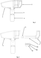
- the spray tip comprises three elements, the handle (1, 3) the nozzle carrier (4) and the removable inserter (2) of the figure 1 .
- the upper part of the handle (1) comprises a hollow compartment for receiving the removable inserter (2).
- the removable inserter (2) comprises three elements, the grip (5), the elongated portion (7) and the tip (6) (see figure 2 ). Once the removable inserter (2) is in place, only the grip (5) of the removable inserter is accessible, the rest, in particular the tip of the elongated portion is securely protected into the compartment.
- the removable inserter (2) is separated from the handle (1).
- the removable inserter comprises the grip (5), the elongated portion (7) terminated by the tip (6) designed for receiving the piston seal (8).
- the grip (5) stays accessible even if the removable inserter is inside the compartment of the handle.
- the compartment is a hollow cavity and is formed in the handle so as to provide a sliding path for the tip (6) and the elongated part (7).
- the piston seal (8) is also represented.
- the piston seal (8) is an independent element provided with the spray tip.
- the concave section is designed to cooperate with the cylindrical nozzle carrier (4).
- the flat section is designed to be placed on the spray gun to guarantee perfect tightness.
- the piston seal is usually in two parts, one is the metallic part and the other one is the plastic/Teflon/rubber part. The resilience of the material of the seal will provide pressure on the seal so that the seal will not leak upon application of the paint.
- the piston seal (8) comprises the Plastic seal (9b) and an O-ring (9a).
- the role of the Plastic seal (9b) (or equivalent material) is to guarantee against any leakage of the pressured paint during the normal operation of the spray gun.
- the O-ring (9a) plays another role.
- Several problems can be encountered during the operation of placing the piston seal inside the spray gun. The first one is holding to the tip of the inserter during the placement of the piston seal.
- other spray tip comprises a piston seal inserter that is part of the handle. The operator extracts the piston seal from the package and slides it into the tip of the inserter. The size of the tip should be small enough to accommodate the passage of the piston seal.
- the inserter should be removed from the hole of the piston seal. In some instances, the friction between the tip of the inserter and the hole of the piston seal is too high and the separation of the inserter from the piston seal is difficult.
- the O-ring (9a) will bring an improvement.
- the purpose of the O-ring (9a) is to hold the piston seal in place.
- the O-ring When the operator pushes the piston seal in its position into the nozzle carrier holder of the spray gun, the O-ring generates a friction between its outer surface and the inner corresponding surface in the nozzle carrier holder. It is then easy to remove the inserter since the friction between the inserter and the piston seal is far less than the friction between the outer surface and the inner corresponding surface in the spray gun.
- O-ring Another advantage of the O-ring is to keep the piston seal in place even if the spray tip, in particular the nozzle carrier (4) is not present in the nozzle carrier holder.
- the nozzle carrier holder can be manipulated without risking that the piston seal falls out and rolls on the floor.
- the removable inserter in order to maintain the removable inserter into the compartment, the removable inserter comprises a protuberance (10) illustrated in the figure 3 .
- the protuberance (10) can be part of the removable inserter of the figure 2 (without the support for the piston seal) or part of the removable inserter of the figure 3 (with the support for the piston seal).
- the protuberance (10) cooperates with a corresponding recess in the compartment (not shown). Once the removable inserter is into the compartment, the combination of the protuberance and the recess avoids the removable inserter from sliding outside the compartment.
- FIG 3 we have a second embodiment of the removable inserter.
- the latter comprises a support (11) for the piston seal (8) so that the piston seal (8) is properly secured inside the compartment.
- the support (11) is preferably in two parts with some elastic property. The support holds the piston seal and therefore it cannot be lost and stays with the removable inserter even if the piston seal has not been used.
- the piston seal (8) is not changed, only the spray tip is changed and the piston seal is therefore in a secure place and can be found for use at a later stage.
- Figure 4 illustrates the removable inserter with the piston seal when the operator removes it from the compartment according to the second embodiment of the invention.
- the compartment comprises a first section to accommodate the tip and the elongated part of the removable inserter and a second section to accommodate the piston seal. It is to be noted that when the removable inserter is in place into the handle, only the grip is visible and accessible by the operator. The piston seal is protected inside the compartment.
- Figure 5 illustrates the removable inserter ready to introduce the piston seal into the nozzle carrier holder.
- the tip of the removable inserter is not cylindrical and could be of any form avoiding the piston seal to rotate (see figure 3 ).
- the tip comprises a first cylindrical section (13) and a second non-cylindrical section (12), the first and second sections are shaped for guiding and holding the piston seal, the second section (12) is present for avoiding the rotation of the piston seal.
- the piston seal comprises a corresponding section not cylindrical so that once the piston seal is introduced on the tip of the removable inserter, the piston seal cannot rotate freely along the axis of the elongated part.
- the O-ring creates a retention force into the cavity of the tip holder and the piston seal stays in this position.
- the removable inserter can be removed from this position and can be reinserted into the compartment of the handle.
- the spray tip in particular the nozzle carrier (4) of the figure 1 can be put in place in the nozzle carrier holder of the spray gun before the piston seal is inserted into the said nozzle carrier holder.
- the inserter of the piston seal is not part of the handle and is removable.
- the inserter it is no longer possible to use the inserter to place the piston seal into its position.
- the nozzle carrier holds an insert preferably made of tungsten carbide for better resistance and longer life span.
- the handle can be of any type of plastic such as Zytel, Delrin, PA 6.6, etc
- the nozzle carrier is made out of stainless steel of possibly different grades
Landscapes
- Nozzles (AREA)
Abstract
The present invention relates generally to fluid spraying systems. More particularly, the invention relates to a spray tip used to define a spray pattern at a sprayer nozzle of the spray gun. It is therefore proposed a spray tip comprising a handle and a nozzle carrier, said handle comprising a hollow compartment, the spray tip further comprising a removable inserter, partly inserted into the compartment, one end of said inserter being shaped to receive and hold a piston seal, the other end comprising a grip.
Description
- The present invention relates generally to fluid spraying systems. More particularly, the invention relates to a spray tip used to define a spray pattern at a sprayer nozzle. Fluid spraying systems are commonly used in a wide variety of applications, from industrial assembly of all kinds to home painting. Handheld sprayers can be used by a human operator, while automated sprayers are typically used in mechanized manufacturing processes. Interchangeable spray tips are commonly used in the painting field to accommodate the type of paint, the coating finish and the spray pattern desired.
- An airless sprayer pumps up and pressurizes the paint without the use of air. The paint is then fed through a small hole (referred to as an orifice) within the spray tip under high pressure which can be up to 530 barf 7700 psi. This process atomizes the paint in a controlled fan width and flow rate. Spray tip size and airless pump pressure determine the paint material flow rate. The spray tip, in particular the nozzle assembly, also creates the fan pattern, spraying angle and spraying volume.
- The spray tip should be often replaced during the painting operation to obtain the right finish, surface coverage and coating thickness for the specific application. The use of the spray tip entails wear and the shape of the spray tends to change over time. This is why the spray guns are designed to receive interchangeable spray tips. The spray tip comprises a nozzle carrier comprising a nozzle assembly which defines the shape of the spray when fluid passes through it. When the nozzle carrier is rotated into the spray position, pressurized fluid (typically paint) is forced forward through the nozzle assembly and exits at high velocity along the central longitudinal axis of the nozzle assembly.
- The spray tip is associated with a piston seal designed to cooperate with the nozzle assembly and having on one side a flat surface, being placed on the spray gun, and the other side, a concave shape for receiving the cylindrical or spherical nozzle carrier.
- The spray tip is made of two parts, the handle and the nozzle carrier. In known executions, for example as illustrated in the document
US 7'328'853 , the handle is shaped so as to receive the piston seal for the correct positioning of the piston seal into the (spray)tip/nozzle carrier holder with the said tip/nozzle carrier holder to be screwed on to the spray gun. An extremity of the handle is terminated by a tip having the same shape as the opening of the piston seal. The operator places the piston seal on the tip of the handle and places the piston seal in the tip/nozzle carrier. - Since the spray tip is often changed, a set comprising the spray tip and the corresponding piston seal is proposed by various manufacturers.
- The inventors have identified various problems. One problem is the loss of the piston seal. The set as described above is generally sold in a package and once open, the piston seal is free to roll out and get lost. Another problem is the contamination of the piston seal in an environment comprising paints everywhere. We are not in a clean laboratory when the spray tip is changed but in a construction/production site with little possibilities to carry out a clean job. In some instance, the spray tip is changed but not the piston seal. In this case the operator has no place to keep the piston seal for later usage in a clean and safe condition.
- Another problem identified by the inventors is the necessity to position the piston seal before positioning the spray tip. This is because the inserter of the piston seal is part of the tip handle. The handle as explained before is shaped to receive temporarily the piston seal during the introduction of the same in the nozzle carrier holder of the spray gun. Then, once the piston seal is properly located into the nozzle carrier holder, the nozzle carrier, part of the spray tip, is inserted into the nozzle carrier holder, having the said tip holder screwed on to the spray gun.
- It is therefore proposed a spray tip comprising a handle and a nozzle carrier, said handle comprising a hollow compartment, the spray tip further comprising a removable inserter, partly inserted into the compartment, one end of said inserter being shaped to receive and hold a piston seal, the other end comprising a grip.
- One main aspect of the present execution is the removable inserter, which is part of the spray tip but can be separated during the positioning of the piston seal. The compartment receives part of the removable inserter, leaving the grip of the removable inserter outside of the compartment so that the operator can pull free the removable inserter.
- Having a removable inserter eases/facilitates the positioning of the piston seal, because the said piston seal is inserted once the nozzle carrier has been inserted into the tip/nozzle carrier holder.
- The present invention will be better understood with the help of the attached figures, namely :
-
Figure 1 illustrates the spray tip with the removable inserter inside the compartment, -
Figure 2 illustrates the spray tip with the removable inserter outside of the compartment, -
Figure 3 illustrates an execution of the removable inserter, -
Figure 4 illustrates the removal inserter having the support for the piston seal, the compartment being shaped for receiving the removable inserter with the piston seal, -
Figure 5 illustrates the removable inserter with the piston seal ready for the operation of placing the piston seal into the nozzle carrier holder of the spray gun. - According to a first embodiment of the present invention, the spray tip comprises three elements, the handle (1, 3) the nozzle carrier (4) and the removable inserter (2) of the
figure 1 . The upper part of the handle (1) comprises a hollow compartment for receiving the removable inserter (2). The removable inserter (2) comprises three elements, the grip (5), the elongated portion (7) and the tip (6) (seefigure 2 ). Once the removable inserter (2) is in place, only the grip (5) of the removable inserter is accessible, the rest, in particular the tip of the elongated portion is securely protected into the compartment. - In
figure 2 , the removable inserter (2) is separated from the handle (1). The removable inserter comprises the grip (5), the elongated portion (7) terminated by the tip (6) designed for receiving the piston seal (8). The grip (5) stays accessible even if the removable inserter is inside the compartment of the handle. The compartment is a hollow cavity and is formed in the handle so as to provide a sliding path for the tip (6) and the elongated part (7). - In
figure 2 , the piston seal (8) is also represented. According to a first embodiment, the piston seal (8) is an independent element provided with the spray tip. We can see the concave section and the flat section. The concave section is designed to cooperate with the cylindrical nozzle carrier (4). The flat section is designed to be placed on the spray gun to guarantee perfect tightness. The piston seal is usually in two parts, one is the metallic part and the other one is the plastic/Teflon/rubber part. The resilience of the material of the seal will provide pressure on the seal so that the seal will not leak upon application of the paint. - In the execution proposed by the present invention, the piston seal (8) comprises the Plastic seal (9b) and an O-ring (9a). The role of the Plastic seal (9b) (or equivalent material) is to guarantee against any leakage of the pressured paint during the normal operation of the spray gun.
- The O-ring (9a) plays another role. Several problems can be encountered during the operation of placing the piston seal inside the spray gun. The first one is holding to the tip of the inserter during the placement of the piston seal. We have explained that other spray tip comprises a piston seal inserter that is part of the handle. The operator extracts the piston seal from the package and slides it into the tip of the inserter. The size of the tip should be small enough to accommodate the passage of the piston seal. However, when the piston seal is in place, the inserter should be removed from the hole of the piston seal. In some instances, the friction between the tip of the inserter and the hole of the piston seal is too high and the separation of the inserter from the piston seal is difficult.
- Another problem can arise when the piston seal is in place. In this case, if the tip holder is manipulated, there is a high risk that the piston seal falls out from its position and cannot be retrieved.
- For the two above mentioned problems, the O-ring (9a) will bring an improvement. The purpose of the O-ring (9a) is to hold the piston seal in place. When the operator pushes the piston seal in its position into the nozzle carrier holder of the spray gun, the O-ring generates a friction between its outer surface and the inner corresponding surface in the nozzle carrier holder. It is then easy to remove the inserter since the friction between the inserter and the piston seal is far less than the friction between the outer surface and the inner corresponding surface in the spray gun.
- Another advantage of the O-ring is to keep the piston seal in place even if the spray tip, in particular the nozzle carrier (4) is not present in the nozzle carrier holder. The nozzle carrier holder can be manipulated without risking that the piston seal falls out and rolls on the floor.
- In a particular embodiment, in order to maintain the removable inserter into the compartment, the removable inserter comprises a protuberance (10) illustrated in the
figure 3 . It is to be noted that the protuberance (10) can be part of the removable inserter of thefigure 2 (without the support for the piston seal) or part of the removable inserter of thefigure 3 (with the support for the piston seal). - The protuberance (10) cooperates with a corresponding recess in the compartment (not shown). Once the removable inserter is into the compartment, the combination of the protuberance and the recess avoids the removable inserter from sliding outside the compartment.
- In
figure 3 , we have a second embodiment of the removable inserter. The latter comprises a support (11) for the piston seal (8) so that the piston seal (8) is properly secured inside the compartment. The support (11) is preferably in two parts with some elastic property. The support holds the piston seal and therefore it cannot be lost and stays with the removable inserter even if the piston seal has not been used. In some cases, the piston seal (8) is not changed, only the spray tip is changed and the piston seal is therefore in a secure place and can be found for use at a later stage. -
Figure 4 illustrates the removable inserter with the piston seal when the operator removes it from the compartment according to the second embodiment of the invention. The compartment comprises a first section to accommodate the tip and the elongated part of the removable inserter and a second section to accommodate the piston seal. It is to be noted that when the removable inserter is in place into the handle, only the grip is visible and accessible by the operator. The piston seal is protected inside the compartment. -
Figure 5 illustrates the removable inserter ready to introduce the piston seal into the nozzle carrier holder. The tip of the removable inserter is not cylindrical and could be of any form avoiding the piston seal to rotate (seefigure 3 ). The tip comprises a first cylindrical section (13) and a second non-cylindrical section (12), the first and second sections are shaped for guiding and holding the piston seal, the second section (12) is present for avoiding the rotation of the piston seal. - The piston seal comprises a corresponding section not cylindrical so that once the piston seal is introduced on the tip of the removable inserter, the piston seal cannot rotate freely along the axis of the elongated part.
- When the operator places the piston seal into the tip holder (nozzle holder), the O-ring creates a retention force into the cavity of the tip holder and the piston seal stays in this position. The removable inserter can be removed from this position and can be reinserted into the compartment of the handle.
- It is apparent from this design that the spray tip, in particular the nozzle carrier (4) of the
figure 1 can be put in place in the nozzle carrier holder of the spray gun before the piston seal is inserted into the said nozzle carrier holder. This is possible since the inserter of the piston seal is not part of the handle and is removable. In the previous known solutions, once the nozzle carrier is inserted into the nozzle carrier holder, it is no longer possible to use the inserter to place the piston seal into its position. - The nozzle carrier holds an insert preferably made of tungsten carbide for better resistance and longer life span. The handle can be of any type of plastic such as Zytel, Delrin, PA 6.6, etc
- The nozzle carrier is made out of stainless steel of possibly different grades
Claims (5)
- Spray tip comprising a handle (1) and a nozzle carrier (4), said handle (1) comprising a hollow compartment, the spray tip further comprising a removable inserter (2), partly inserted into the compartment, said removable inserter (2) comprising a grip (2a), an elongated portion (7) and a tip (6), the tip (6) of said removable inserter (2) being shaped to receive and hold a piston seal (8), the compartment of the handle (1) being shaped to receive the tip and the elongated part of the removable inserter (2).
- Spray tip of claim 1, wherein the tip (6) of the removable inserter (2) comprises a first cylindrical section (13) and a second non-cylindrical section (12), the first and second sections are shaped for guiding and holding the piston seal (8), the second section (12) avoiding the rotation of the piston seal (8).
- Spray tip according to the claims 1 or 2, wherein the removable inserter (2) further comprises a protuberance (10) along the elongated portion (7) cooperating with a recess into the compartment so that the removable inserter (2) holds while inserted into the compartment of the handle (2).
- Spray tip according to any of the claims 1 to 3, wherein the removable inserter (2) further comprises a support (11) designed for holding the piston seal (8), said support (11) being entirely inside the compartment while the removable inserter (2) is inserted into the compartment.
- Spray tip according to any of the claims 1 to 4, wherein the piston seal (8) comprises a first seal (9b) for sealing the connection between the piston seal (8) and the spray gun, and a second seal, in the form of an O-ring (9a) for holding the piston seal (8) into its position into the nozzle carrier holder of the spray gun once the removable inserter (2) is removed.
Priority Applications (5)
| Application Number | Priority Date | Filing Date | Title |
|---|---|---|---|
| EP23209391.4A EP4552748A1 (en) | 2023-11-13 | 2023-11-13 | Spray tip for airless spray gun |
| AU2024382033A AU2024382033A1 (en) | 2023-11-13 | 2024-11-08 | Spray tip for airless spray gun |
| PCT/EP2024/081740 WO2025103906A1 (en) | 2023-11-13 | 2024-11-08 | Spray tip for airless spray gun |
| KR1020267015255A KR20260093363A (en) | 2023-11-13 | 2024-11-08 | Spray tip for airless spray guns |
| CN202480070848.3A CN122138871A (en) | 2023-11-13 | 2024-11-08 | Spray tip for airless spray gun |
Applications Claiming Priority (1)
| Application Number | Priority Date | Filing Date | Title |
|---|---|---|---|
| EP23209391.4A EP4552748A1 (en) | 2023-11-13 | 2023-11-13 | Spray tip for airless spray gun |
Publications (1)
| Publication Number | Publication Date |
|---|---|
| EP4552748A1 true EP4552748A1 (en) | 2025-05-14 |
Family
ID=88833896
Family Applications (1)
| Application Number | Title | Priority Date | Filing Date |
|---|---|---|---|
| EP23209391.4A Withdrawn EP4552748A1 (en) | 2023-11-13 | 2023-11-13 | Spray tip for airless spray gun |
Country Status (5)
| Country | Link |
|---|---|
| EP (1) | EP4552748A1 (en) |
| KR (1) | KR20260093363A (en) |
| CN (1) | CN122138871A (en) |
| AU (1) | AU2024382033A1 (en) |
| WO (1) | WO2025103906A1 (en) |
Citations (5)
| Publication number | Priority date | Publication date | Assignee | Title |
|---|---|---|---|---|
| US3593920A (en) * | 1968-05-31 | 1971-07-20 | Delavan Manufacturing Co | Spray head |
| US4629121A (en) * | 1982-07-19 | 1986-12-16 | Hengesbach Robert W | Flow control nozzle and shutoff valve having screen-carrying passage in rotatable stem |
| US7328853B2 (en) | 2005-11-09 | 2008-02-12 | Tritech Industries Inc. | Reversible spray tip unit |
| US20120280066A1 (en) * | 2010-03-11 | 2012-11-08 | Wagner Spray Tech Corporation | Multiple spray tip turret assembly for paint sprayer |
| US20210283640A1 (en) * | 2020-03-11 | 2021-09-16 | Harbor Freight Tools Usa, Inc. | Paint sprayer saddle seal insertion tool and method |
-
2023
- 2023-11-13 EP EP23209391.4A patent/EP4552748A1/en not_active Withdrawn
-
2024
- 2024-11-08 KR KR1020267015255A patent/KR20260093363A/en active Pending
- 2024-11-08 CN CN202480070848.3A patent/CN122138871A/en active Pending
- 2024-11-08 AU AU2024382033A patent/AU2024382033A1/en active Pending
- 2024-11-08 WO PCT/EP2024/081740 patent/WO2025103906A1/en active Pending
Patent Citations (5)
| Publication number | Priority date | Publication date | Assignee | Title |
|---|---|---|---|---|
| US3593920A (en) * | 1968-05-31 | 1971-07-20 | Delavan Manufacturing Co | Spray head |
| US4629121A (en) * | 1982-07-19 | 1986-12-16 | Hengesbach Robert W | Flow control nozzle and shutoff valve having screen-carrying passage in rotatable stem |
| US7328853B2 (en) | 2005-11-09 | 2008-02-12 | Tritech Industries Inc. | Reversible spray tip unit |
| US20120280066A1 (en) * | 2010-03-11 | 2012-11-08 | Wagner Spray Tech Corporation | Multiple spray tip turret assembly for paint sprayer |
| US20210283640A1 (en) * | 2020-03-11 | 2021-09-16 | Harbor Freight Tools Usa, Inc. | Paint sprayer saddle seal insertion tool and method |
Also Published As
| Publication number | Publication date |
|---|---|
| WO2025103906A1 (en) | 2025-05-22 |
| AU2024382033A1 (en) | 2026-05-28 |
| KR20260093363A (en) | 2026-06-19 |
| CN122138871A (en) | 2026-06-02 |
Similar Documents
| Publication | Publication Date | Title |
|---|---|---|
| EP2265387B1 (en) | Disposable spray gun cartridge | |
| EP3342487B1 (en) | Spray tip | |
| US6971590B2 (en) | Liquid spray gun with manually rotatable frictionally retained air cap | |
| US7201336B2 (en) | Liquid spray gun with non-circular horn air outlet passageways and apertures | |
| US7032839B2 (en) | Liquid spray gun with manually separable portions | |
| EP3284544B1 (en) | Air cap arrangement and spray gun | |
| US8726831B2 (en) | Apparatus and methods for purging material application device | |
| US11701670B2 (en) | Spray tip | |
| CN102307671A (en) | Spray device having an adjustment member for needle valve opening range | |
| EP3259077B1 (en) | Sprayer adapter | |
| US20120097765A1 (en) | Fine Finish Airless Spray Tip Assembly for a Spray Gun | |
| US5415352A (en) | Spray system manifold apparatus and method | |
| US5094402A (en) | High performance spray head | |
| US20140230726A1 (en) | Spray coating system and method | |
| US20080078849A1 (en) | Disposable spray gun cartridge | |
| WO2025103906A1 (en) | Spray tip for airless spray gun | |
| CN108014940B (en) | Pneumatic spraying assembly, flow restrictor and spraying device | |
| US20210170426A1 (en) | Tip piece for spray tip | |
| KR20230029978A (en) | Adapter for connecting fluid reservoir can to fluid applicator | |
| WO2025180598A1 (en) | Spray tip holder for airless spray gun | |
| JP5619981B2 (en) | Spray gun | |
| WO2023237752A1 (en) | Cleaning tool for foam guns | |
| CN121532257A (en) | Spray gun | |
| CN120936441A (en) | Fluid sprayer and component of fluid sprayer |
Legal Events
| Date | Code | Title | Description |
|---|---|---|---|
| PUAI | Public reference made under article 153(3) epc to a published international application that has entered the european phase |
Free format text: ORIGINAL CODE: 0009012 |
|
| STAA | Information on the status of an ep patent application or granted ep patent |
Free format text: STATUS: THE APPLICATION HAS BEEN PUBLISHED |
|
| AK | Designated contracting states |
Kind code of ref document: A1 Designated state(s): AL AT BE BG CH CY CZ DE DK EE ES FI FR GB GR HR HU IE IS IT LI LT LU LV MC ME MK MT NL NO PL PT RO RS SE SI SK SM TR |
|
| STAA | Information on the status of an ep patent application or granted ep patent |
Free format text: STATUS: THE APPLICATION IS DEEMED TO BE WITHDRAWN |
|
| 18D | Application deemed to be withdrawn |
Effective date: 20251115 |