EP4552682A1 - Drug-dispensing urethral implant - Google Patents
Drug-dispensing urethral implant Download PDFInfo
- Publication number
- EP4552682A1 EP4552682A1 EP24211397.5A EP24211397A EP4552682A1 EP 4552682 A1 EP4552682 A1 EP 4552682A1 EP 24211397 A EP24211397 A EP 24211397A EP 4552682 A1 EP4552682 A1 EP 4552682A1
- Authority
- EP
- European Patent Office
- Prior art keywords
- implant
- wire
- drug dispensing
- drug
- wires
- Prior art date
- Legal status (The legal status is an assumption and is not a legal conclusion. Google has not performed a legal analysis and makes no representation as to the accuracy of the status listed.)
- Granted
Links
Images




Classifications
-
- A—HUMAN NECESSITIES
- A61—MEDICAL OR VETERINARY SCIENCE; HYGIENE
- A61M—DEVICES FOR INTRODUCING MEDIA INTO, OR ONTO, THE BODY; DEVICES FOR TRANSDUCING BODY MEDIA OR FOR TAKING MEDIA FROM THE BODY; DEVICES FOR PRODUCING OR ENDING SLEEP OR STUPOR
- A61M27/00—Drainage appliance for wounds or the like, i.e. wound drains, implanted drains
- A61M27/002—Implant devices for drainage of body fluids from one part of the body to another
- A61M27/008—Implant devices for drainage of body fluids from one part of the body to another pre-shaped, for use in the urethral or ureteral tract
-
- A—HUMAN NECESSITIES
- A61—MEDICAL OR VETERINARY SCIENCE; HYGIENE
- A61M—DEVICES FOR INTRODUCING MEDIA INTO, OR ONTO, THE BODY; DEVICES FOR TRANSDUCING BODY MEDIA OR FOR TAKING MEDIA FROM THE BODY; DEVICES FOR PRODUCING OR ENDING SLEEP OR STUPOR
- A61M31/00—Devices for introducing or retaining media, e.g. remedies, in cavities of the body
- A61M31/002—Devices for releasing a drug at a continuous and controlled rate for a prolonged period of time
-
- A—HUMAN NECESSITIES
- A61—MEDICAL OR VETERINARY SCIENCE; HYGIENE
- A61F—FILTERS IMPLANTABLE INTO BLOOD VESSELS; PROSTHESES; DEVICES PROVIDING PATENCY TO, OR PREVENTING COLLAPSING OF, TUBULAR STRUCTURES OF THE BODY, e.g. STENTS; ORTHOPAEDIC, NURSING OR CONTRACEPTIVE DEVICES; FOMENTATION; TREATMENT OR PROTECTION OF EYES OR EARS; BANDAGES, DRESSINGS OR ABSORBENT PADS; FIRST-AID KITS
- A61F2/00—Filters implantable into blood vessels; Prostheses, i.e. artificial substitutes or replacements for parts of the body; Appliances for connecting them with the body; Devices providing patency to, or preventing collapsing of, tubular structures of the body, e.g. stents
- A61F2/02—Prostheses implantable into the body
- A61F2/04—Hollow or tubular parts of organs, e.g. bladders, tracheae, bronchi or bile ducts
-
- A—HUMAN NECESSITIES
- A61—MEDICAL OR VETERINARY SCIENCE; HYGIENE
- A61B—DIAGNOSIS; SURGERY; IDENTIFICATION
- A61B17/00—Surgical instruments, devices or methods
- A61B17/32—Surgical cutting instruments
- A61B17/3209—Incision instruments
- A61B2017/32096—Incision instruments for slowly cutting through tissue, e.g. stent like temporary implants having sharp edges
-
- A—HUMAN NECESSITIES
- A61—MEDICAL OR VETERINARY SCIENCE; HYGIENE
- A61F—FILTERS IMPLANTABLE INTO BLOOD VESSELS; PROSTHESES; DEVICES PROVIDING PATENCY TO, OR PREVENTING COLLAPSING OF, TUBULAR STRUCTURES OF THE BODY, e.g. STENTS; ORTHOPAEDIC, NURSING OR CONTRACEPTIVE DEVICES; FOMENTATION; TREATMENT OR PROTECTION OF EYES OR EARS; BANDAGES, DRESSINGS OR ABSORBENT PADS; FIRST-AID KITS
- A61F2/00—Filters implantable into blood vessels; Prostheses, i.e. artificial substitutes or replacements for parts of the body; Appliances for connecting them with the body; Devices providing patency to, or preventing collapsing of, tubular structures of the body, e.g. stents
- A61F2/02—Prostheses implantable into the body
- A61F2/04—Hollow or tubular parts of organs, e.g. bladders, tracheae, bronchi or bile ducts
- A61F2002/047—Urethrae
-
- A—HUMAN NECESSITIES
- A61—MEDICAL OR VETERINARY SCIENCE; HYGIENE
- A61M—DEVICES FOR INTRODUCING MEDIA INTO, OR ONTO, THE BODY; DEVICES FOR TRANSDUCING BODY MEDIA OR FOR TAKING MEDIA FROM THE BODY; DEVICES FOR PRODUCING OR ENDING SLEEP OR STUPOR
- A61M2210/00—Anatomical parts of the body
- A61M2210/10—Trunk
- A61M2210/1078—Urinary tract
- A61M2210/1089—Urethra
- A61M2210/1096—Male
Definitions
- the disclosed technique relates to medical implant devices, in general, and to drug-dispensing urethral implant devices, in particular.
- Urethral implants in general are known in the art.
- BPH benign prostatic hyperplasia
- BPH is a medical condition, also known as prostate enlargement in which the prostate gland increases in size leading to a variety of medical issues such as urination problems (e.g., weak urine drainage, bladder control loss, slow or prolonged urination, increased urination frequency), as well as more serious conditions that can lead to lower urinary tract infections (LUTS), bladder stones, kidney and/or bladder damage, etc.
- urination problems e.g., weak urine drainage, bladder control loss, slow or prolonged urination, increased urination frequency
- LUTS lower urinary tract infections
- the implant includes four wires, an anchoring leaflet, a distal end, and a proximal end. Each of the wires is coupled between the proximal end and the distal end.
- the anchoring leaflet extends from the distal end and is positioned between two of the wires. The wires are wider at the proximal end than at the distal end to prevent the implant from moving from the bladder neck into the urethra wen implanted.
- the anchoring leaflet prevents the implant from moving from the bladder neck into the bladder.
- the method involves inducing infarction via the application of continuous radial pressure an at least one of urethral wall and tissue surrounding the urethral wall.
- the method includes the procedures of delving the implant (that is removable) to a vicinity of at least one of a bladder neck of a bladder and a prostatic urethra, releasing the removable implant, and applying continuous pressure by the removable implant.
- the removable implant has at least one foldable wire and an anchor capable of seif-expanding. Once the implant is released, both the foldable wire and anchor expand to prevent movement of the implant along the urethral wall in a direction toward the bladder.
- the applied continuous pressure creates longitudinal incisions in the urethral wall and in tissue surrounding the urethral wall in a radial direction from a urethral axis outwardly.
- the removable implant is extracted.
- U.S. Patent No.: US 11,304,724 B2 titled "Incising Implant for the Prostatic Urethra” to Kilemnik, is directed at an incising implant for creating incisions in the prostatic urethra of a subject.
- the implant includes at least two closed-shaped wires, and an anchor.
- Each wire has a proximal section, a distal section and two longitudinal sections that extend between the proximal section and the distal section.
- Each of the closed-shaped wires is elastic thereby being compressible from an expanded configuration to a compressed configuration.
- the longitudinal sections of each of the wires are adjoined with another longitudinal section of another one of the wires along their length.
- the incising implant In the expanded configuration the incising implant is configured to incise tissue in the prostatic urethra.
- the at least two wires diverge at their distal sections such that the distal sections form a simple closed curve shape at a terminus of the incising implant in the expanded configuration.
- the anchor is closed-shaped and extends outwardly from the proximal section and though one of the closed-shaped wires in the expanded configuration.
- the implant includes at least two struts, an anchor, and at least one drug dispensing wire.
- the at least two struts extend longitudinally between a proximal end and a distal end of the implant.
- Each of the struts is flexible between a compressed configuration and an expanded configuration.
- the compressed configuration enables delivery of the implant to a stricture in the urethra.
- the expanded configuration facilitates expansion of the stricture.
- the anchor extends outwardly from at least one of the proximal end and the distal end. The anchor is for anchoring the implant in the urethra.
- the at least one drug dispensing wire is adjoined to and extends longitudinally along, at least one of the struts.
- the drug dispensing wire is embedded with a drug for releasing into the urethra.
- an implant for the urethra of a subject includes three closed-shaped wires, an anchor, and at least one drug dispensing wire.
- Each closed-shape wire includes two longitudinal sections extending between a proximal end and a distal end of the implant.
- Each longitudinal section of a closed-shaped wire is adjoined along its length with another longitudinal section of another closed-shaped wire.
- the closed-shaped wires are configured to engage with and to expand urethral tissue at a stricture in the urethra.
- the anchor includes a closed-shape wire.
- the anchor is for anchoring the implant to the urethra.
- the at least one drug dispensing wire is, adjoined to and extends longitudinally along at least one of the closed-shaped wires.
- the drug dispensing wire is embedded with a drug for releasing to the urethra.
- Figure 1A is a schematic illustration of a urethral implant, shown in an expanded configuration, constructed and operative in accordance with an embodiment of the disclosed technique
- the disclosed technique overcomes the disadvantages of the prior art by providing an implant for the urethra (herein “urethral implant") of a subject (i.e., patient, person, implantee), in which the implant includes at least two struts, an anchor, and at least one drug dispensing wire.
- the at least two struts can be a single wire structure (e.g., a closed-shape loop).
- the implant includes a proximal end, a distal end, and a central-portion (middle-portion) disposed between the proximal and distal ends.
- the struts extend longitudinally between the proximal end and the distal end of the implant.
- the struts are flexible between a compressed configuration that enables delivery of the implant to a stricture (i.e., a narrowing, constriction) in the urethra, and an expanded configuration that facilitates expansion of the urethral passage in general, and the stricture in particular.
- the anchor extends outwardly from at least one of the proximal end and the distal end, and is configured and operative for anchoring the implant within the urethra of the subject.
- the drug dispensing wire is adjoined to, and extends longitudinally along, at least one of the struts.
- the drug dispensing wire is embedded with a drug for releasing into the urethra of the subject.
- the at least two struts are made of a single continuous wire that forms a closed-shape. Alternatively, the at least two struts are separate entities joined together to form a continuous wire.
- the struts generally provide a mechanical structural framework to the urethral implant that allows it to compress and to expand.
- the drug dispensing wire generally provides a therapeutic action of the drug to target tissues of the urethra (e.g., stricture).
- the urethral implants of the disclosed technique provide a synergistic effect between the mechanical actions of the wire (struts) and the therapeutic action of drug dispensing wire that extends along a wire-to-tissue engaging area (i.e., the area of which the wire (struts) contact tissues of the subject within the urethra).
- the wires mechanically engage and apply pressure to urethral tissues at the wire-to-tissue engaging area, while simultaneously the drug dispensing wire makes contact with the same urethral tissues as wire (struts) and delivers a drug to those tissues (i.e., targeted drug delivery).
- the urethral implant of the disclosed technique is configured and operative to self-expand by employing shape-memory alloy (SMA) materials, such as nickel titanium (NiTi) (also known by the trade name "Nitinol” (Nickel Titanium Naval Ordinance Laboratories)), having a memorized expanded and compressed configurations.
- SMA shape-memory alloy
- NiTi nickel titanium
- Nickel Titanium Naval Ordinance Laboratories Nickel Titanium Naval Ordinance Laboratories
- the urethral implant structure is generally hollow to allow urine to pass therethrough (i.e., through the voids) when the urethral implant is implanted in the expanded configuration within the urethra of the subject.
- the urethral implants of the disclosed technique are capable of incising tissues, specifically, the wires are configured to apply continuous (ischemic) pressure on tissues of the urethra (e.g., prostatic urethra) thereby creating incisions (i.e., longitudinal struts or wires creating corresponding longitudinal incisions), which can lead to infarction or tissue necrosis thus reshaping and expanding the urethra so urine can flow more easily for subjects suffering from BPH).
- the wires can be equipped with at least one jagged edge (e.g., along the length of the wires or at least partially along the length thereof) for further facilitating the creation of incisions.
- the urethral implant doesn't incise tissues of the urethra, it doesn't include jagged edges.
- the urethral implants are generally removable from the subject (via an extraction mechanism). It is noted that all urethral implants disclosed herein are non-vascular implants, i.e., not implanted within blood vessels where blood flows, but rather implanted within the urethra where urine flows.
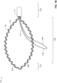
- Figure 1A is a schematic illustration of a urethral implant, generally referenced 100, shown in an expanded configuration, constructed and operative in accordance with an embodiment of the disclosed technique.
- Figure 1B is a schematic illustration of the urethral implant of Figure 1A including a proximal cap, constructed and operative in accordance with the embodiment of the disclosed technique.
- Figure 1C is the urethral implant of Figure 1B in a compressed configuration, constructed and operative in accordance with the embodiment of the disclosed technique.
- Urethral implant 100 includes a tissue engaging wire 102 (interchangeably denoted herein as "wire”), a tissue engaging anchor 104 (interchangeably denoted herein as “anchor”), and a drug dispensing wire 106.
- Wire 102 includes two struts 102A and 102B extending longitudinally along a proximal portion 110A (interchangeably denoted herein “proximal end”), a central portion 110B (interchangeably denoted herein “mid-section”), and a distal portion 110C (interchangeably denoted herein “distal end”), and generally along a longitudinal axis 101L of urethral implant 100.
- Two struts 102A and 102B shown in Figures 1A and 1B are continuous, i.e., are made of a single piece of wire, which converge at proximal end 110A.
- struts 102A and 102B are separate pieces (not shown) that are mechanically joined together at distal end 110C, and converging at proximal end 110A.
- Central portion 110B is defined to be between proximal end 110A and distal end 110C.
- the length of central portion 110B along longitudinal axis 101L is generally longer than the combined lengths of proximal portion 110A and distal portion 110C.
- Urethral implant 100 is compressible between an expanded configuration having a length L 1 and a width W 1 (strut width W 2 ), and a compressed configuration having a length L 2 and a width W 3 as shown in Figure 1C (strut width W 4 - not shown).
- Figures 1A and 1B show that struts 102A and 102B of wire 102 are geometrically symmetric about longitudinal axis 101L (having the same geometric properties such as equal length, width, and curvature), as well as materially the same (e.g., made of the same material and having the same mechanical properties such as elasticity, strength, malleability, resilience, and the like).
- a viable alternative configuration is where struts 102A and 102B are geometrically asymmetric about longitudinal axis 101L (e.g., at least one of their lengths, widths, curvatures, or other geometrical properties are different with respect to each other), or materially different (i.e., the struts are not made of exactly the same material or have different mechanical properties such as flexibility, strength, and the like).
- Wire 102 is made of medical-grade bio-compatible materials such as titanium, gold, stainless steel, metal alloys such as nickel titanium (Nitinol), tantalum alloy, and the like.
- wire 102 is made of a polymer (e.g., a shape-memory polymer).
- FIGS 1A , 1B , and 1C show urethral implant 100 in an expanded configuration.
- urethral implant 100 When urethral implant 100 is implanted in the subject, it facilitates expansion of a stricture within the urethra of the subject, by applying pressure to surrounding tissues.
- urethra implant 100 generally functions as a mechanical spring that is compressible and expandable having intermediate compression states between two extremities (i.e., fully expanded configuration and fully compressed configuration).
- the main structural members of urethral implant, namely, struts 102A and 102B are flexible between the compressed configuration (shown in Fig. 1C ) that enables delivery of urethral implant 100 to the stricture in the urethra, and the expanded configuration (shown in Figs.
- a sheath 114 is configured and operative to enfold urethral implant 100 in the compressed configuration, which allows delivery of urethral implant 100 within the body of the subject via a delivery device (not shown) toward a desired anatomical location within the urethra, typically to the stricture, where urethral implant is deployed by releasing from sheath 114 thereby self-expanding to the expanded configuration shown in Figures 1A and 1B .
- Sheath 114 is typically a hollow tube (e.g., cylindrical and of medical-grade) that is configured to cover, encapsulate, enfold and compress urethral implant 100 in the compressed configuration.
- Anchor 104 is typically a continuous wire structure that includes two sides embodied as two struts 104A and 104B, which extend outwardly from proximal end 110A into central portion 110B, to one side of urethral implant 100 of longitudinal axis 101L (i.e., a proximal-to-distal direction).
- Struts 104A and 104B of anchor 104 are generally made from a single continuous piece of wire converging at proximal end 110A.
- struts 104A and 104B are separate pieces (not shown) that are mechanically joined together at an apex (i.e., a tip of anchor 104).
- Anchor 104 is flexible between the compressed configuration ( Figures 1A and 1B ) and the expanded configuration ( Figure 1C ). Anchor 104 has the capability to self-expand into the expanded configuration once released from sheath 114.
- Anchor 104 is generally arcuate defining a closed-shape (e.g., closed loop) having an internal hole and bilateral symmetry of the two struts. Alternatively, anchor 104 is bilaterally asymmetric.
- Anchor 104 is constructed and operative to engage with, and attach (anchor) to tissues of the urethra of the subject in the expanded configuration. Anchor 104 can be detached from tissues when urethral implant 100 is removed from the subject.
- Anchor 104 is made of the same material of wire 102.
- anchor 104 is not made of exactly the same materials of wire 102.
- the wire making up anchor 104 is thinner than the wire making up wire 102, as shown in Figures 1A and 1B .
- the wires making up anchor 104 and wire 102 have the same thickness (not shown).
- Other alternative configurations of anchor 104 are possible (not shown) (e.g., a closed polygonal shape, etc.).
- urethral implant 100 in the urethra is subject-specific (i.e., depending on anatomical factors, as well stricture-dependent factors (e.g., stricture dimensions, stricture tissue characteristics, etc.).
- a plurality of anchors such as a second anchor that extends outwardly from distal end 110C into central portion 110B at the other side of urethral implant 100 with respect to longitudinal axis 101L (i.e., the side that is different from the extension of the first anchor).
- anchors constructed and operative to extend from the same end (i.e., either proximal end 110A or distal end 110C) toward its contrariwise direction (i.e., either a distal-to-proximal direction defined from distal end 110C to proximal end 110A, or a proximal-to-distal direction defined from proximal end 110A to distal end 110C).
- Drug dispensing wire 106 is adjoined (coupled) to (e.g., continuously wound around) wire 102 along the length of struts 102A and 102B starting and ending at proximal end 110A (i.e., the two ends of drug dispensing wire 106 end at proximal end 110A).
- the two ends of drug dispensing wire 106 can either be open or closed.
- the two ends of drug dispensing wire 106 make contact with each other thus defining a closed shape.
- Drug dispensing wire 106 is adjoined to struts 102A and 102B by helically winding along the entire length thereof (as shown in Figures 1A and 1B ).
- An alternative coupling configuration between drug dispensing wire 106 and closed-shaped wire 102 is parallel coupling (both wires extending in parallel to each other, i.e., non-helically - not shown).
- Drug dispensing wire 106 has an overall length that is greater than the length of wire 102.
- Drug dispensing wire 106 is embedded with a drug that is dispensed (i.e., released, administered) into the urethra when urethral implant 100 is implanted within the subject.
- the drug includes a chemical substance that is configured to produce or perform a biological effect on the subject.
- Example drugs (medications) include sirolimus (rapamycin), and everolimus.
- the drugs may generally be formulated to include a time-release mechanism (e.g., liposomes) also known as modified-release dosage that functions to deliver the drug over a period of time (i.e., gradually, and not “immediate-release” formulations) that dissolves, diffuses (or both) at a controlled rate (e.g., controlled release, sustained release, delayed-release, extended release, etc.).
- a time-release mechanism e.g., liposomes
- modified-release dosage that functions to deliver the drug over a period of time (i.e., gradually, and not “immediate-release” formulations) that dissolves, diffuses (or both) at a controlled rate (e.g., controlled release, sustained release, delayed-release, extended release, etc.).
- the drug can be coated (fully or partially) onto drug dispensing wire 106.
- proximal end 110A of urethral implant 100 includes a proximal cap 112 that covers the ends (termini) of the wire 102, the ends of the wire of anchor 104, as well the ends of drug dispensing wire 106.
- Proximal cap 112 is typically made of a medical-grade plastic material (e.g., polyethylene that substantially doesn't degrade within the body, etc.).
- drug dispensing wire 106 Prior to drug dissolution in the body following implantation, drug dispensing wire 106 has a greater surface contact area (i.e., implant-to-tissue engaging surface area) in comparison to that of wire 102. Once drug dispensing wire 106 is implanted, the drug is configured to gradually dissolve at a controlled rate according to its characteristic time-release drug profile. Drug dispensing wire 106 is made of a single strand or multiple strands of a material (e.g., fibrous such as cotton fiber, synthetic fiber such as polyester, etc.) that can absorb as well as exude the embedded drug when urethral implant 100 is implanted.
- a material e.g., fibrous such as cotton fiber, synthetic fiber such as polyester, etc.
- drug dispensing wire 106 is made of a biodegradable material that dissolves when implanted in the urethra of the implantee. According to this alternative, both the embedded drug and drug dispensing wire 106 dissolve over time (e.g., at the same rate, or at different rates). Drug dispensing wire 106 is compressible between the compressed configuration and expanded configuration of urethral implant 100.
- Alternative configurations (not shown) for drug dispensing wire 106 include adjoining to (e.g., wound helically around) only one of struts 102A and 102B.
- Another alternative configuration involves having a plurality of drug dispensing wires, where each wire is embedded with a different drug or the same drug. In the case of at least two different drug dispensing wires, each wire is embedded with a different drug having a different time-release profile.
- two drug dispensing wires can be embedded with the same drug but with different time-release profiles (linear, non-linear, burst, etc.).
- the different drug dispensing wires may be composed of different materials.
- urethral implant 100 is delivered to a stricture of the subject's urethra (e.g., a constriction at the prostatic urethra), the implant expands to the expanded configuration, which is configured to apply continuous pressure to surrounding tissues of the urethra at the stricture, thereby expanding the stricture (e.g., reshaping and expanding the bladder neck and prostatic urethra).
- Anchor 104 expands to the expanded configuration and engages with surrounding tissues of the urethra, thereby anchoring urethral implant 100 in position.
- Anchor 104 facilitates urethral implant 100 to be relatively immobile (thus averting inadvertent migration into the bladder of the subject while being implanted).
- Urethral implant 100 is configured and operative to apply continuous pressure thereby expanding the internal cross-section at the stricture, thus increasing the ability of urine flow through the urethra. While urethral implant 100 is implanted, drug dispensing wire 106 is configured to release the drug at a controlled rate at the implantation site. Urethral implant 100 is enabled for removal from the urethra (via an implant extraction mechanism - not shown).
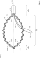
- FIG. 2 is a schematic illustration of the urethral implant, generally referenced 150, shown in an expanded configuration, having twisted wires, constructed and operative in accordance with another embodiment of the disclosed technique.
- Urethral implant 150 is generally similar to urethral implant 100 of Figures 1A-1C in structure and function, apart from urethral implant 150 including two twisted or intertwined wires (i.e., a twisted wire pair) instead of only one wire compared to urethral implant 100.
- urethral implant 150 includes two wires 152 1 and 152 2 , an anchor 154, a drug dispensing wire 156, and a proximal cap 162.
- proximal cap 162 is optional.
- Wires 152 1 and 152 2 are joined together (helically twisted or intertwined together), and each wire includes two strut sections extending longitudinally along a proximal portion 160A (interchangeably denoted herein “proximal end”), a central portion 160B (interchangeably denoted herein “mid-section”), and a distal portion 160C (interchangeably denoted herein “distal end”), and generally along a longitudinal axis 161L of urethral implant 150.
- wire 152 1 includes two strut sections 152 1 A and 152 1 B
- wire 152 2 includes two strut sections 152 2 A and 152 2 B.
- Struts 152 1 A and 152 1 B of wire 152 1 are continuous (i.e., made of a single piece of wire) and converge at proximal end 160A.
- struts 152 2 A and 152 2 B of wire 152 2 are continuous (i.e., made of a single piece of wire) and converge at proximal end 160A.
- 152 1 A and 152 1 B of wire 152 1 are separate pieces that are mechanically joined together at distal end 160C and converge at proximal end 160A.
- struts 152 2 A and 152 2 B of wire 152 2 are separate pieces that are mechanically joined together at distal end 160C and converge at proximal end 160A.
- Central portion 160B is defined to be between proximal end 160A and distal end 160C.
- Wires 152 1 and 152 2 are similar to wire 102 of urethral implant 102 in function.
- anchor 154, and proximal cap 162 are similar in structure and function to anchor 104 and proximal cap 112 (respectively) of urethral implant 100 ( Figs. 1A-1C ).
- Urethral implant 150 is compressible between an expanded configuration and a compressed configuration (similarly to urethral implant 100).
- Wires 152 1 and 152 2 generally have the same structural properties (e.g., equal length, thickness, cross-section), as well as the same material properties (e.g., made of the same material and having the same mechanical properties such as elasticity, strength, malleability, resilience, and the like).
- An alternative configuration (not shown) is where wires 152 1 and 152 2 are dissimilar with respect to at least one attribute such as structurally, geometrically (e.g., length, thickness, curvature), and materially different (i.e., not made of exactly the same material or have different mechanical properties such as flexibility, strength, and the like).
- Wires 152 1 and 152 2 are generally made of medical-grade bio-compatible materials (similar to wire 102).
- Anchor 154 is identical to anchor 104 of Figs. 1A-1C .
- Anchor is a continuous wire structure that includes two sides embodied as two struts 154A and 154B, which extend outwardly from proximal end 160A into central portion 160B, to one side of urethral implant 150 of longitudinal axis 161L.
- Struts 154A and 154B are generally made from a single continuous piece of wire converging at proximal end 160A.
- struts 104A and 104B are separate pieces (not shown) that are mechanically joined together at an apex (i.e., a tip of anchor 104).
- Anchor 154 is flexible between the compressed configuration and the expanded configuration.
- Anchor 104 has the capability to self-expand into the expanded configuration once released from a delivery sheath (e.g., sheath 114 of Figure 1C ).
- Anchor 154 is generally arcuate defining a closed shape (e.g., closed loop) having an internal hole and bilateral symmetry of the two struts.
- Anchor 154 is constructed and operative to engage with, and attach (anchor) to tissues of the urethra of the subject in the expanded configuration. Anchor 154 can be detached from tissues when urethral implant 150 is removed from the subject.
- Anchor 154 is made of the same material of wires 152 1 and 152 2 . Alternatively, anchor 154 is not made of exactly the same materials of 152 1 and 152 2 .
- Drug dispensing wire 156 is similar to drug dispensing wire 106 of Figs. 1A-1C , in structure, composition, and function. Drug dispensing wire 156 is adjoined to (e.g., continuously and helically wound around) wires 152 1 and 152 2 along the length of the wire's corresponding struts 152 1 A and 152,B for wire 152 2 A and 152 2 B for wire 152 2 . Drug dispensing wire 156 starts as well as ends at proximal end 160A (i.e., such that its two ends terminate at proximal end 160A).
- Drug dispensing wire 106 is adjoined to the struts of wires 152 1 and 152 2 by helically winding circumferentially and along their entire length.
- An alternative coupling configuration between drug dispensing wire 156 and the closed-shaped wires is a parallel coupling (i.e., the wires extending in parallel to each other, i.e., non-helically).
- Drug dispensing wire 156 has an overall length that is greater than the length of each wire 152 1 and 152 2 , and according to one configuration it is less than the length of wires 152 1 and 152 2 combined.
- drug dispensing wire 156 can be tightly helically coiled such that its overall length is greater than the length of wires 152 1 and 152 2 combined.
- Drug dispensing wire 156 is embedded with the same drug or drugs as drug dispensing wire 106.
- the drug functions to dispense (i.e., be released) into the urethra when urethral implant 150 is implanted within the subject.
- the drug is configured to gradually dissolve at a controlled rate according to its characteristic time-release drug profile.
- Drug dispensing wire 156 is made of a single strand or multiple strands of a material (e.g., fibrous) that can absorb as well as exude the embedded drug when urethral implant 150 is implanted. Drug dispensing wire 156 is compressible between the compressed configuration and expanded configuration of urethral implant 150.
- a material e.g., fibrous
- urethral implant 150 When urethral implant 150 is implanted in the subject, it facilitates expansion of a stricture within the urethra of the subject, by applying pressure to surrounding tissues.
- Urethral implant 150 has two wires 152 1 and 152 2 (as opposed to one wire in urethral implant 100), enabling it to apply more force per area (pressure) to surrounding tissue than that of urethral implant 100.
- Urethral implant 150 is capable of storing more mechanical energy when compressed than urethral implant 100.
- Urethral implant 150 is compressible between two extremities: a fully compressed configuration and a fully expanded configuration, where continuous intermediate compression states are viable between these two extremities.
- Urethral implant 150 provides a synergistic effect between the mechanical action of wires 152 1 and 152 2 , and the therapeutic action of drug dispensing wire 156 that extends along the wire-to-tissue engaging area.
- wires 152 1 and 152 2 mechanically engage and apply pressure to urethral tissues at the wire-to-tissue engaging area, while simultaneously drug dispensing wire 156 makes contact with the same urethral tissues as wires 152 1 and 152 2 and delivers the drug to those same tissues (i.e., targeted drug delivery).
- Figure 3A is a schematic illustration of a urethral implant, generally referenced 200, shown in an expanded configuration, constructed and operative in accordance with a further embodiment of the disclosed technique.
- Figure 3B is a schematic illustration of the urethral implant of Figure 3A including a proximal cap, constructed and operative in accordance with the embodiment of the disclosed technique.
- Figure 3C is a schematic illustration of the urethral implant of Figure 2B shown from a distal-to-proximal direction A, constructed and operative in accordance with the embodiment of the disclosed technique.
- Urethral implant 200 is generally constructed from a wireframe structure that includes three categories of closed-shape sub-structures having different form and function.
- a first category sub-structure is a mechanical structural framework of urethral implant 200 that includes three closed-shapes for engaging with urethral tissue, incising the urethral tissue, and expanding the urethral tissue at a particular urethral location where a stricture occurs (i.e., a constriction).
- a second category sub-structure is an anchor that includes at least one closed-shape structure for engaging with urethral tissue and anchoring urethral implant 200 in position.
- a third category sub-structure includes at least one drug dispensing wire that is embedded with a drug for dispensing within the urethra of the subject.
- Urethral implant 100 defines a proximal section 210A, a central section 210B, and a distal section 210C.
- urethral implant 200 includes three closed-shaped wires 202A, 202B, and 202C (i.e., the first category sub-structure, which is the wireframe structure), an anchor 204 (i.e., the second category sub-structure), and a drug dispensing wire 206 (i.e., a third category sub-structure), as shown in Figures 3A-3C .
- urethral implant 200 includes a proximal cap 212 at proximal end 210A, as shown in Figures 3B and 3C .
- proximal cap 212 is absent (i.e., optional).
- Each closed-shaped wire includes two longitudinal sections extending between proximal end 210A and distal end 210C.
- Each closed-shape wire may include a lateral section between the two lateral sections.
- closed-shape wire 202A includes longitudinal sections 202A 1 and 202A 2 , and a lateral section 203A connecting between longitudinal sections 202A 1 and 202A 2 (as shown in Figure 3C ).
- Closed-shape wire 202B includes longitudinal sections 202B 1 and 202B 2 , and a lateral section 203B connecting between longitudinal sections 202B 1 and 202B 2 (as shown in Figure 3C ).
- Closed-shape wire 202C includes longitudinal sections 202C 1 and 202C 2 , and a lateral section 203C connecting between longitudinal sections 202C, and 202C 2 (as shown in Figure 3C ). Each longitudinal section of a closed-shaped wire is adjoined along its length with another longitudinal section of another one closed-shaped wire.
- each closed-shape is constructed from a single continuous wire that defines at least two longitudinal sections. Alternatively, there are three sections (a lateral section between two longitudinal sections).
- the method of adjoining the wires is by helically twisting one around the other (longitudinal sections), as a twisted or intertwined wire pair where one wire is twists clockwise while the other wire twists counterclockwise (left/right-handed twists).
- the wires are composed of the same material, and have the same physical attributes (e.g., width, cross-section).
- the wires are not the same in at least one respect (e.g., composition, physical attribute, etc.).
- urethral implant 200 forms a triangular pyramidal structure having a triangular base that is formed from lateral sections 203A, 203B, and 203C at distal end 210C, and an apex at proximal end 210A where longitudinal wires converge (at proximal cap 212 shown in Figures 3B and 3C and without a proximal cap shown in Figure 3A ).
- Proximal cap 212 covers the ends (termini) of the first, second, and third category wires at proximal section 210A as shown in Figures 3B and 3C .
- proximal cap 112 covers the ends (termini) of wires 202A, 202B, 202C, the ends of anchor 204, as well the ends of drug dispensing wire 206, at proximal section 120A ( Figs. 3B and 3C ).
- wires 202A, 202B, and 202C are closed curves (i.e., having no endpoints).
- Anchor 204 is identical to anchor 104 of Figures 1A-1C , and anchor 154 of Figure 2 .
- Anchor 204 is a continuous wire structure that includes two sides embodied as two struts 204A and 204B, which extend outwardly from proximal end 210A into central portion 210B, to one side of urethral implant 200 and terminate at a terminus (i.e., the tip, apex of anchor 204).
- Anchor 204 generally originates from proximal end 210A, passes through one of the closed-shaped wires (e.g., closed-shaped wire 202B as shown in Figures 3B and 3C ).
- Struts 204A and 204B are generally made from a single continuous piece of wire that converges at two points, namely the origin, i.e., proximal end 210A and the terminus of anchor 204.
- struts 204A and 204B are separate pieces (not shown) that are mechanically joined together at the apex or tip of anchor.
- anchor 204 is a closed curve (i.e., having no endpoints).
- Anchor 204 is flexible between the compressed configuration and the expanded configuration. Anchor 204 has the capability to self-expand into the expanded configuration once released from a delivery sheath (e.g., sheath 114 of Figure 1C ).
- Anchor 204 is generally arcuate defining a closed shape (e.g., closed loop) having an internal hole and bilateral symmetry of the two struts. When in the expanded configuration, anchor 204 extends beyond the width of the closed-shaped wires, thereby effectively widening the total width of urethral implant 200. Anchor 204 is constructed and operative to engage with, and attach (anchor) to tissues of the urethra of the subject in the expanded configuration. Anchor 204 can be detached from tissues when urethral implant 204 is removed from the subject. Anchor 204 is made of the same material as that of the closed-shaped wires. Alternatively, anchor 204 is not made of exactly the same materials that compose the closed-shaped wires.
- a closed shape e.g., closed loop
- Drug dispensing wire 206 is similar to drug dispensing wire 106 of Figs. 1A-1C , and drug dispensing wire 156 of Fig. 2 in structure, composition, and function. Drug dispensing wire 206 is coupled to (i.e., adjoined continuously and helically wound around) wires longitudinal sections 202A 1 and 202A 2 of closed-shaped wire 202A, longitudinal sections 202B 1 and 202B 2 of closed-shaped wire 202B, and longitudinal sections 202C 1 and 202C 2 of closed-shaped wire 202C.
- drug dispensing wire 206 is adjoined to (e.g., helically wound around) lateral sections 203A and 203B but not adjoined along the length of lateral section 203C, as distinctly shown in Figure 3C .
- drug dispensing wire 206 is adjoined to lateral section 203C (i.e., adjoined to all longitudinal and lateral wires).
- Drug dispensing wire 206 is continuous and originates as well as terminates at proximal end 210A (i.e., such that its two ends terminate at proximal end 210A).
- Drug dispensing wire 206 is helically wounded circumferentially and along the entire length of the longitudinal sections of each of the closed-shaped wires.
- the twisting or intertwining method of drug dispensing wire 206 around the longitudinal sections can be clockwise or counterclockwise (e.g., left or right handed twisting).
- the overall length of drug dispensing wire 206 is greater than the length of each closed-shaped wire.
- Drug dispensing wire 206 is compressible between the compressed configuration and the expanded configuration of urethral implant 200.
- Drug dispensing wire 206 is embedded with the same drug or drugs as embedded in drug dispensing wire 106.
- the drug is dispensed (i.e., be released, administered) into the urethra when urethral implant 200 is implanted within the subject.
- drug dispensing wire 206 is implanted along with urethral implant 200, the drug gradually dissolves at a controlled rate according to its characteristic time-release drug profile.
- the drug includes a chemical substance that is configured to produce or perform a biological effect on the subject.
- Drug dispensing wire 206 is made of a single strand or multiple strands of a material (e.g., fibrous) that can absorb as well as exude the embedded drug when urethral implant 200 is implanted.
- Alternative configurations (not shown) for drug dispensing wire 206 include adjoining to (e.g., wound helically around) only one of the longitudinal sections.
- Another alternative configuration involves having a plurality of drug dispensing wires, where each wire is embedded with a different drug or the same drug. In the case of at least two different drug dispensing wires, each wire is embedded with a different drug having a different time-release profile.
- two drug dispensing wires can be embedded with the same drug but with different time-release profiles (linear, non-linear, burst, etc.).
- the different drug dispensing wires may be composed of different materials.
- Urethral implant 200 (including closed-shape wires 202A, 202B, and 202C, anchor 204, and drug dispensing wire 206) is compressible between an expanded configuration and a compressed configuration (similarly to urethral implants 100 and 150).
- Closed-shape wires 202A, 202B, and 202C generally have the same structural properties (e.g., dimensions such as length, thickness, cross-section), as well as the same material properties (e.g., made of the same material and having the same mechanical properties such as elasticity, strength, malleability, resilience, and the like).
- wires 202A, 202B, and 202C are dissimilar with respect to at least one attribute such as structurally, geometrically (e.g., length, thickness, curvature), and materially different (i.e., not made of exactly the same material or have different mechanical properties such as flexibility, strength, and the like).
- Wires 202A, 202B, and 202C are generally made of medical-grade bio-compatible materials (similar to wire 102 and wires 152 1 and 152 2 of the preceding embodiments).
- urethral implant 200 Following implantation of urethral implant 200 in the subject, the implant facilitates expansion of a stricture within the urethra, by applying pressure to surrounding tissues.
- the dual intertwined wires (a twisted wire pair) of urethral implant 200 are capable of storing more mechanical energy when in a compressed state than that of single-wire urethral implant 100.
- Urethral implant 200 is generally compressible between two extremities: a fully compressed configuration and a fully expanded configuration, where continuous intermediate compression states are viable between the two extremities.
- the urethral implant can include more than two intertwined wires (e.g., longitudinally) such as a wire bundle.
- Urethral implant 200 provides a synergistic effect between the mechanical action of the closed-shaped wires 202A, 202B, and 202C and the therapeutic action of drug dispensing wire 206 that extends along the wire-to-tissue engaging area.
- the longitudinal sections 202A 1 , 202A 2 , 202B 1 , 202B 2 , 202C 1 , and 202C 2 of the closed-shaped wires mechanically engage and apply pressure to urethral tissues at the wire-to-tissue engaging area, while simultaneously drug dispensing wire 206 makes contact with the same urethral tissues as the longitudinal sections of the closed-shaped wires and delivers the drug to those same tissues (i.e., targeted drug delivery).
- FIG 4 is a schematic illustration of a urethral implant, generally referenced 250, having a plurality of discontinuous drug dispensing wires, constructed and operative in accordance with another embodiment of the disclosed technique.
- Urethral implant 250 is the same as urethral implant 200 of Figures 3A-3C except for the drug dispensing wire having a plurality of discontinuous sections.
- Urethral implant 250 defines a proximal section 260A, a central section 260B, and a distal section 260C.
- urethral implant 250 includes three closed-shaped wires 252A, 252B, and 252C, an anchor 254, a proximal cap 262, and a plurality of drug dispensing wires 256 1 , 256 2 , 256 3 , 256 4 , 256 5 , 256 6 , and 256 7 .
- urethral implant 250 can include a plurality of N drug dispensing wires 256 1,..., 256 N (where N is a positive integer greater than 1).
- urethral implant 250 includes seven separate and discontinuous drug dispensing wires (as an example), each of different lengths, and each of which is coupled to at least part of one closed-shaped wires 252A, 252B, and 252C.
- drug dispensing wire 256 1 is coupled to wires 252A 1 and 252C 2
- drug dispensing wire 256 2 is coupled to wires 252A 1 and 252C 2
- drug dispensing wire 256 3 is coupled to wires 252A 1 , 252C 2 , 252B 1 and 252A 2
- drug dispensing wire 256 4 is coupled to wires 252A 1 , 252C 2 , 252B 2 and 252C 1
- drug dispensing wire 256 5 is coupled to wires 252A 2 , and 252B 1
- drug dispensing wire 256 6 is coupled to wires 252B 2 and 252C 1
- drug dispensing wire 256 7 is coupled to wires 252B 2 , 252C 1 , 252A 1 , and 252C 2 .
- drug dispensing wires 256 1,..., 256 7 are of equal lengths.
- drug dispensing wires 256 1,..., 256 7 are the same and have the same characteristics, namely, are embedded with the same drug composition, and the same drug time-release profile, physical attributes (e.g., length, width, cross-section, curvature, torsion, etc.).
- at least one of drug dispensing wire of wires 256 1,..., 256 7 is different with respect to the other drug dispensing wires in at least one characteristic, such as drug composition, drug time-release profile, mechanism of action (MOA), physical attributes, and the like.
- drug dispensing wire 256 1 is embedded with the drug sirolimus
- drug dispensing wire 256 3 is embedded with the drug everolimus.
- different combinatorial combinations of different characteristics of different drug dispensing wires are possible.
- Closed-shaped wires 252A, 252B, and 252C, as well as anchor 254, and proximal cap 262 are the same in structure and function as closed-shaped wires 202A, 202B, and 202C, anchor 204, and proximal cap 212 (respectively), described in conjunction with Figures 3A-3C .
- the description of elements with respect to Figures 3A-3C applies to those same elements of urethral implant 250 of Figure 4 .
- FIG. 5 is a schematic illustration of a urethral implant, generally referenced 300, having drug dispensing wires coupled to closed-shaped wires that include an anchor, constructed and operative in accordance with a further embodiment of the disclosed technique.
- Urethral implant 300 is the same as urethral implant 200 of Figures 3A-3C except for an additional drug dispensing wire coupled to the anchor.
- urethral implant 300 includes three closed-shaped wires 302A, 302B, and 302C, an anchor 304, a drug dispensing wire 306, a drug dispensing wire 308, and a proximal cap 312.
- Urethral implant 300 defines a proximal section 310A, a central section 310B, and a distal section 310C.
- Anchor 304 is identical to anchor 204 of Figures 3A-3C .
- Anchor 304 is a continuous wire structure that includes two sides embodied as two struts 304A and 304B, which extend outwardly from proximal end 310A into central portion 310B, to one side of urethral implant 300 and terminate at a terminus (i.e., the tip, apex of anchor 304).
- Struts 304A and 304B are generally made from a single continuous piece of wire that converges at two points, namely the origin, i.e., proximal end 310A and the terminus of anchor 304.
- Anchor 304 is flexible between the compressed configuration and the expanded configuration.
- Anchor 304 has the capability to self-expand into the expanded configuration.
- Anchor 304 is generally arcuate defining a closed shape (e.g., closed loop) having an internal hole and bilateral symmetry of the two struts 304A and 304B.
- Drug dispensing wire 308 is coupled to (i.e., adjoined continuously and helically wound around) struts 304A and 304B of anchor 304. Drug dispensing wire 308 and anchor 304 are compressible between the compressed configuration and the expanded configuration of urethral implant 300. In one configuration, drug dispensing wire 308 is different than drug dispensing wire 306. Differences include different structure, composition, type of drug embedded, drug time-release profile, function, and the like. For example, drug dispensing wire 308 is composed of a fiber or fiber strand that is thinner and shorter than that of drug dispensing wire 306, as illustrated in Figure 5 .
- drug dispensing wire 308 can be embedded with a different drug than that of drug dispensing wire 306 (e.g., non-steroidal anti-inflammatory drugs (NSAIDS), etc.).
- drug dispensing wire 308 is the same as drug dispensing wire 306 in terms of structure, composition, function, and the like.
- each one of struts 304A and 304B has coupled therewith a different drug dispensing wire. In such a configuration, their differences can be manifested by at least one differentiating characteristic (e.g., with respect to structure, composition, drug embedding, mechanism of action (MOA), etc.).
- Closed-shaped wires 302A, 302B, 302C, as well as anchor 304, drug dispensing wire 306, and proximal cap 312 are the same in structure and function as closed-shaped wires 202A, 202B, and 202C, anchor 204, and proximal cap 212 (respectively), as described in conjunction with Figures 3A-3C .
- the description of elements with respect to Figures 3A-3C applies to those same elements of urethral implant 300 of Figure 5 .
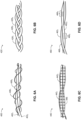
- Figures 6A, 6B, 6C, and 6D are schematic illustrations of various configurations of drug dispensing wires, constructed and operative in accordance with the embodiments of the disclosed technique.
- the wires of the urethral implant wireframe structure as well as the drug dispensing wires described hereinbelow in conjunction with Figures 6A-6D are respectfully the same as the wires of the urethral implant wireframe structure and drug dispensing wires heretofore described in the previous embodiments in conjunction with Figures 3A-3C , 4 , and 5 .
- Figure 6A is schematic illustration showing a double helix configuration, generally referenced 400, of two drug dispensing wires helically wound about two wires of the urethral implant of the disclosed technique.
- Figure 6A illustrates two urethral implant wires 402 1 and 402 2 as well as two drug dispensing wires 406 1 and 406 2 (only partially shown, i.e., not their full lengths).
- drug dispensing wires 406 1 and 406 2 are embodied as two helices in a double helix configuration, helically wound about wires 402 1 and 402 2 (i.e., coupled therewith).
- Drug dispensing wires 406 1 and 406 2 are identical or congruent (differing only by a translation or position along wires 402 1 and 402 2 ) (i.e., they have the same geometry, same composition, embedded with the same drug, etc.). Alternatively, drug dispensing wires 406 1 and 406 2 are different in at least one respect (e.g., structurally different, embedded with different drugs, composed of different materials, have different time-release profiles, etc.).
- Figure 6B is a schematic illustration showing a three-strand braid configuration, generally referenced 420, including three drug dispensing wires for winding about two wires of the urethral implants of the disclosed technique.
- Figure 6B illustrates three drug dispensing wires 426 1 , 426 2 , and 426 3 (only partially shown, i.e., not their full lengths) for winding about the wireframe structure (not shown) of the urethral implants of the disclosed technique.
- drug dispensing wires 426 1 , 426 2 , and 426 3 are identical (differing only by a translation or position along wires) (i.e., they have the same geometry, same composition, embedded with the same drug, etc.).
- At least one drug dispensing wire 426 1 , 426 2 , and 426 3 is different in at least one respect to at least one other drug dispensing wire (e.g., structurally different, embedded with different drugs, composed of different materials, have different time-release profiles, etc.).
- Figure 6C is a schematic illustration showing a drug dispensing fabric configuration, generally referenced 440, covering two wires of the urethral implant of the disclosed technique. Specifically, Figure 6C illustrates wires 442 1 , and 442 2 of the urethral implant, and a drug dispensing fabric 446 that covers the wires (only partially shown, i.e., not their full lengths). Drug dispensing fabric 446 is embedded with a drug according to the principles heretofore described (e.g., drug dispensing wire 306). Fabric 446 can be woven or nonwoven (e.g., bonded together).
- drug dispensing fabric 446 is a cloth (e.g., cotton, polyester) that is embedded with a drug that can be dispensed when implanted within the body of the subject.
- fabric 446 is a material other than cloth (e.g., polymer) that is woven into a pattern. Multiple materials can be interwoven into various patterns (e.g., plain weave, etc.).
- Figure 6D is a schematic illustration, showing two different drug dispensing wire configurations, generally referenced 460, for two wires of the urethral implants of the disclosed technique. Specifically, Figure 6D illustrates wires 462 1 , and 462 2 of the urethral implant, and three drug dispensing wire groups.
- the first drug dispensing wire group includes one drug dispensing wire 466, coupled to and extending in parallel to wire 462 1 .
- a second drug dispensing wire group includes a plurality of discrete drug dispensing wires 466 2 coupled to and extending perpendicularly to the direction of extension of wire 462 2 , partially along the length of wire 462 2 .
- a third drug dispensing wire group includes a plurality of discrete drug dispensing wires 466 3 coupled to and extending in an X-pattern or crisscross pattern along the direction of extension of wire 462 2 , partially along the length of wire 462 2 .
- Alternative configurations are viable (e.g., oblique pattern, O-pattern, V-pattern, etc.). It will be appreciated by persons skilled in the art that the disclosed technique is not limited to what has been particularly shown and described hereinabove.
Landscapes
- Health & Medical Sciences (AREA)
- Engineering & Computer Science (AREA)
- General Health & Medical Sciences (AREA)
- Public Health (AREA)
- Animal Behavior & Ethology (AREA)
- Veterinary Medicine (AREA)
- Life Sciences & Earth Sciences (AREA)
- Biomedical Technology (AREA)
- Heart & Thoracic Surgery (AREA)
- Anesthesiology (AREA)
- Hematology (AREA)
- Medicinal Chemistry (AREA)
- Bioinformatics & Cheminformatics (AREA)
- Chemical & Material Sciences (AREA)
- Cardiology (AREA)
- Gastroenterology & Hepatology (AREA)
- Vascular Medicine (AREA)
- Oral & Maxillofacial Surgery (AREA)
- Transplantation (AREA)
- Pulmonology (AREA)
- Urology & Nephrology (AREA)
- Ophthalmology & Optometry (AREA)
- Otolaryngology (AREA)
- Prostheses (AREA)
Abstract
Description
- The disclosed technique relates to medical implant devices, in general, and to drug-dispensing urethral implant devices, in particular.
- Urethral implants in general are known in the art. There is a category of urethral implants that are implanted within the urethras of men, employed for treating benign prostatic hyperplasia (BPH). BPH is a medical condition, also known as prostate enlargement in which the prostate gland increases in size leading to a variety of medical issues such as urination problems (e.g., weak urine drainage, bladder control loss, slow or prolonged urination, increased urination frequency), as well as more serious conditions that can lead to lower urinary tract infections (LUTS), bladder stones, kidney and/or bladder damage, etc. Various treatment options have been proposed and utilized over the years, which include oral medications (e.g., alpha blockers), invasive surgical procedures (e.g., transurethral resection of the prostate (TURP), transurethral incision of the prostate (TUIP)), as well as minimally invasive treatments (e.g., prostatic stent insertion, transurethral microwave thermotherapy (TUMT), transurethral needle ablation (TUNA), transurethral electrovaporization (TUVP)), Holmium laser enucleation of the prostate (HoLEP), etc. Each therapeutic technique has its inherent advantages and disadvantages.
- One category of such techniques employs the use of a urethral implant device, such as that disclosed in U.S. Patent No.:
US 9,848,905 B2 - The method involves inducing infarction via the application of continuous radial pressure an at least one of urethral wall and tissue surrounding the urethral wall. The method includes the procedures of delving the implant (that is removable) to a vicinity of at least one of a bladder neck of a bladder and a prostatic urethra, releasing the removable implant, and applying continuous pressure by the removable implant. The removable implant has at least one foldable wire and an anchor capable of seif-expanding. Once the implant is released, both the foldable wire and anchor expand to prevent movement of the implant along the urethral wall in a direction toward the bladder. The applied continuous pressure creates longitudinal incisions in the urethral wall and in tissue surrounding the urethral wall in a radial direction from a urethral axis outwardly. At an appearance of a predetermined condition, the removable implant is extracted.
- U.S. Patent No.:
US 11,304,724 B2 - It is an object of the disclosed technique to provide a novel implant device for the urethra of a subject. The implant includes at least two struts, an anchor, and at least one drug dispensing wire. The at least two struts extend longitudinally between a proximal end and a distal end of the implant. Each of the struts is flexible between a compressed configuration and an expanded configuration. The compressed configuration enables delivery of the implant to a stricture in the urethra. The expanded configuration facilitates expansion of the stricture. The anchor extends outwardly from at least one of the proximal end and the distal end. The anchor is for anchoring the implant in the urethra. The at least one drug dispensing wire is adjoined to and extends longitudinally along, at least one of the struts. The drug dispensing wire is embedded with a drug for releasing into the urethra. In accordance with the disclosed technique, there is thus provided an implant for the urethra of a subject. The implant includes three closed-shaped wires, an anchor, and at least one drug dispensing wire. Each closed-shape wire includes two longitudinal sections extending between a proximal end and a distal end of the implant. Each longitudinal section of a closed-shaped wire is adjoined along its length with another longitudinal section of another closed-shaped wire. The closed-shaped wires are configured to engage with and to expand urethral tissue at a stricture in the urethra. The anchor includes a closed-shape wire. The anchor is for anchoring the implant to the urethra. The at least one drug dispensing wire is, adjoined to and extends longitudinally along at least one of the closed-shaped wires. The drug dispensing wire is embedded with a drug for releasing to the urethra.
- The disclosed technique will be understood and appreciated more fully from the following detailed description taken in conjunction with the drawings in which:
Figure 1A is a schematic illustration of a urethral implant, shown in an expanded configuration, constructed and operative in accordance with an embodiment of the disclosed technique; -
Figure 1B is a schematic illustration of the urethral implant ofFigure 1A including a proximal cap, constructed and operative in accordance with the embodiment of the disclosed technique; -
Figure 1C is the urethral implant ofFigure 1B in a compressed configuration, constructed and operative in accordance with the embodiment of the disclosed technique; -
Figure 2 is a schematic illustration of the urethral implant, shown in an expanded configuration, having twisted wires, constructed and operative in accordance with another embodiment of the disclosed technique; -
Figure 3A is a schematic illustration of a urethral implant, shown in an expanded configuration, constructed and operative in accordance with a further embodiment of the disclosed technique; -
Figure 3B is a schematic illustration of the urethral implant ofFigure 3A including a proximal cap, constructed and operative in accordance with the embodiment of the disclosed technique; -
Figure 3C is a schematic illustration of the urethral implant ofFigure 3B shown from a distal-to-proximal direction A, constructed and operative in accordance with the embodiment of the disclosed technique; -
Figure 4 is a schematic illustration of a urethral implant having a plurality of discontinuous drug dispensing wires, constructed and operative in accordance with another embodiment of the disclosed technique; -
Figure 5 is a schematic illustration of a urethral implant having drug dispensing wires coupled to closed-shaped wires that include an anchor, constructed and operative in accordance with a further embodiment of the disclosed technique; and -
Figures 6A, 6B, 6C, and 6D , are schematic illustrations of various configurations of drug dispensing wires, constructed and operative in accordance with the embodiments of the disclosed technique. - The disclosed technique overcomes the disadvantages of the prior art by providing an implant for the urethra (herein "urethral implant") of a subject (i.e., patient, person, implantee), in which the implant includes at least two struts, an anchor, and at least one drug dispensing wire. The at least two struts can be a single wire structure (e.g., a closed-shape loop). The implant includes a proximal end, a distal end, and a central-portion (middle-portion) disposed between the proximal and distal ends. The struts extend longitudinally between the proximal end and the distal end of the implant. The struts are flexible between a compressed configuration that enables delivery of the implant to a stricture (i.e., a narrowing, constriction) in the urethra, and an expanded configuration that facilitates expansion of the urethral passage in general, and the stricture in particular. The anchor extends outwardly from at least one of the proximal end and the distal end, and is configured and operative for anchoring the implant within the urethra of the subject. The drug dispensing wire is adjoined to, and extends longitudinally along, at least one of the struts. The drug dispensing wire is embedded with a drug for releasing into the urethra of the subject. The at least two struts are made of a single continuous wire that forms a closed-shape. Alternatively, the at least two struts are separate entities joined together to form a continuous wire.
- The struts generally provide a mechanical structural framework to the urethral implant that allows it to compress and to expand. The drug dispensing wire generally provides a therapeutic action of the drug to target tissues of the urethra (e.g., stricture). The urethral implants of the disclosed technique provide a synergistic effect between the mechanical actions of the wire (struts) and the therapeutic action of drug dispensing wire that extends along a wire-to-tissue engaging area (i.e., the area of which the wire (struts) contact tissues of the subject within the urethra). Specifically, the wires (struts) mechanically engage and apply pressure to urethral tissues at the wire-to-tissue engaging area, while simultaneously the drug dispensing wire makes contact with the same urethral tissues as wire (struts) and delivers a drug to those tissues (i.e., targeted drug delivery).
- The urethral implant of the disclosed technique is configured and operative to self-expand by employing shape-memory alloy (SMA) materials, such as nickel titanium (NiTi) (also known by the trade name "Nitinol" (Nickel Titanium Naval Ordinance Laboratories)), having a memorized expanded and compressed configurations. The urethral implant structure is generally hollow to allow urine to pass therethrough (i.e., through the voids) when the urethral implant is implanted in the expanded configuration within the urethra of the subject. The urethral implants of the disclosed technique are capable of incising tissues, specifically, the wires are configured to apply continuous (ischemic) pressure on tissues of the urethra (e.g., prostatic urethra) thereby creating incisions (i.e., longitudinal struts or wires creating corresponding longitudinal incisions), which can lead to infarction or tissue necrosis thus reshaping and expanding the urethra so urine can flow more easily for subjects suffering from BPH). In addition, the wires can be equipped with at least one jagged edge (e.g., along the length of the wires or at least partially along the length thereof) for further facilitating the creation of incisions. In an alternative configuration where the urethral implant doesn't incise tissues of the urethra, it doesn't include jagged edges.
- The urethral implants are generally removable from the subject (via an extraction mechanism). It is noted that all urethral implants disclosed herein are non-vascular implants, i.e., not implanted within blood vessels where blood flows, but rather implanted within the urethra where urine flows.
- Reference is now made to
Figures 1A ,1B , and1C .Figure 1A is a schematic illustration of a urethral implant, generally referenced 100, shown in an expanded configuration, constructed and operative in accordance with an embodiment of the disclosed technique.Figure 1B is a schematic illustration of the urethral implant ofFigure 1A including a proximal cap, constructed and operative in accordance with the embodiment of the disclosed technique.Figure 1C is the urethral implant ofFigure 1B in a compressed configuration, constructed and operative in accordance with the embodiment of the disclosed technique.Urethral implant 100 includes a tissue engaging wire 102 (interchangeably denoted herein as "wire"), a tissue engaging anchor 104 (interchangeably denoted herein as "anchor"), and adrug dispensing wire 106. -
Wire 102 includes twostruts proximal portion 110A (interchangeably denoted herein "proximal end"), acentral portion 110B (interchangeably denoted herein "mid-section"), and adistal portion 110C (interchangeably denoted herein "distal end"), and generally along alongitudinal axis 101L ofurethral implant 100. Twostruts Figures 1A and1B are continuous, i.e., are made of a single piece of wire, which converge atproximal end 110A. Alternatively, struts 102A and 102B are separate pieces (not shown) that are mechanically joined together atdistal end 110C, and converging atproximal end 110A.Central portion 110B is defined to be betweenproximal end 110A anddistal end 110C. The length ofcentral portion 110B alonglongitudinal axis 101L is generally longer than the combined lengths ofproximal portion 110A anddistal portion 110C.Urethral implant 100 is compressible between an expanded configuration having a length L1 and a width W1 (strut width W2), and a compressed configuration having a length L2 and a width W3 as shown inFigure 1C (strut width W4 - not shown).Figures 1A and1B show that struts 102A and 102B ofwire 102 are geometrically symmetric aboutlongitudinal axis 101L (having the same geometric properties such as equal length, width, and curvature), as well as materially the same (e.g., made of the same material and having the same mechanical properties such as elasticity, strength, malleability, resilience, and the like). A viable alternative configuration (not shown) is where struts 102A and 102B are geometrically asymmetric aboutlongitudinal axis 101L (e.g., at least one of their lengths, widths, curvatures, or other geometrical properties are different with respect to each other), or materially different (i.e., the struts are not made of exactly the same material or have different mechanical properties such as flexibility, strength, and the like).Wire 102 is made of medical-grade bio-compatible materials such as titanium, gold, stainless steel, metal alloys such as nickel titanium (Nitinol), tantalum alloy, and the like. According to an alternative configuration,wire 102 is made of a polymer (e.g., a shape-memory polymer). -
Figures 1A ,1B , and1C showurethral implant 100 in an expanded configuration. Whenurethral implant 100 is implanted in the subject, it facilitates expansion of a stricture within the urethra of the subject, by applying pressure to surrounding tissues. In this respect,urethra implant 100 generally functions as a mechanical spring that is compressible and expandable having intermediate compression states between two extremities (i.e., fully expanded configuration and fully compressed configuration). The main structural members of urethral implant, namely, struts 102A and 102B are flexible between the compressed configuration (shown inFig. 1C ) that enables delivery ofurethral implant 100 to the stricture in the urethra, and the expanded configuration (shown inFigs. 1A and1B ). With specific reference toFigure 1C , asheath 114 is configured and operative to enfoldurethral implant 100 in the compressed configuration, which allows delivery ofurethral implant 100 within the body of the subject via a delivery device (not shown) toward a desired anatomical location within the urethra, typically to the stricture, where urethral implant is deployed by releasing fromsheath 114 thereby self-expanding to the expanded configuration shown inFigures 1A and1B .Sheath 114 is typically a hollow tube (e.g., cylindrical and of medical-grade) that is configured to cover, encapsulate, enfold and compressurethral implant 100 in the compressed configuration. -
Anchor 104 is typically a continuous wire structure that includes two sides embodied as twostruts proximal end 110A intocentral portion 110B, to one side ofurethral implant 100 oflongitudinal axis 101L (i.e., a proximal-to-distal direction).Struts anchor 104 are generally made from a single continuous piece of wire converging atproximal end 110A. Alternatively, struts 104A and 104B are separate pieces (not shown) that are mechanically joined together at an apex (i.e., a tip of anchor 104).Anchor 104 is flexible between the compressed configuration (Figures 1A and1B ) and the expanded configuration (Figure 1C ).Anchor 104 has the capability to self-expand into the expanded configuration once released fromsheath 114.Anchor 104 is generally arcuate defining a closed-shape (e.g., closed loop) having an internal hole and bilateral symmetry of the two struts. Alternatively,anchor 104 is bilaterally asymmetric.Anchor 104 is constructed and operative to engage with, and attach (anchor) to tissues of the urethra of the subject in the expanded configuration.Anchor 104 can be detached from tissues whenurethral implant 100 is removed from the subject.Anchor 104 is made of the same material ofwire 102. Alternatively,anchor 104 is not made of exactly the same materials ofwire 102. Typically, the wire making upanchor 104 is thinner than the wire making upwire 102, as shown inFigures 1A and1B . Alternatively, the wires making upanchor 104 andwire 102 have the same thickness (not shown). Other alternative configurations ofanchor 104 are possible (not shown) (e.g., a closed polygonal shape, etc.). - The breadth of expansion of
urethral implant 100 in the urethra is subject-specific (i.e., depending on anatomical factors, as well stricture-dependent factors (e.g., stricture dimensions, stricture tissue characteristics, etc.). According to an alternative embodiment, there is a plurality of anchors (not shown), such as a second anchor that extends outwardly fromdistal end 110C intocentral portion 110B at the other side ofurethral implant 100 with respect tolongitudinal axis 101L (i.e., the side that is different from the extension of the first anchor). Further alternatively, there are two anchors (not shown) constructed and operative to extend from the same end (i.e., eitherproximal end 110A ordistal end 110C) toward its contrariwise direction (i.e., either a distal-to-proximal direction defined fromdistal end 110C toproximal end 110A, or a proximal-to-distal direction defined fromproximal end 110A todistal end 110C). -
Drug dispensing wire 106 is adjoined (coupled) to (e.g., continuously wound around)wire 102 along the length ofstruts proximal end 110A (i.e., the two ends ofdrug dispensing wire 106 end atproximal end 110A). The two ends ofdrug dispensing wire 106 can either be open or closed. The two ends ofdrug dispensing wire 106 make contact with each other thus defining a closed shape.Drug dispensing wire 106 is adjoined tostruts Figures 1A and1B ). An alternative coupling configuration betweendrug dispensing wire 106 and closed-shapedwire 102 is parallel coupling (both wires extending in parallel to each other, i.e., non-helically - not shown).Drug dispensing wire 106 has an overall length that is greater than the length ofwire 102.Drug dispensing wire 106 is embedded with a drug that is dispensed (i.e., released, administered) into the urethra whenurethral implant 100 is implanted within the subject. The drug includes a chemical substance that is configured to produce or perform a biological effect on the subject. Example drugs (medications) include sirolimus (rapamycin), and everolimus. The drugs may generally be formulated to include a time-release mechanism (e.g., liposomes) also known as modified-release dosage that functions to deliver the drug over a period of time (i.e., gradually, and not "immediate-release" formulations) that dissolves, diffuses (or both) at a controlled rate (e.g., controlled release, sustained release, delayed-release, extended release, etc.). The drug can be coated (fully or partially) ontodrug dispensing wire 106. - With particular reference to
Figures 1B and1C ,proximal end 110A ofurethral implant 100 includes aproximal cap 112 that covers the ends (termini) of thewire 102, the ends of the wire ofanchor 104, as well the ends ofdrug dispensing wire 106.Proximal cap 112 is typically made of a medical-grade plastic material (e.g., polyethylene that substantially doesn't degrade within the body, etc.). - Prior to drug dissolution in the body following implantation,
drug dispensing wire 106 has a greater surface contact area (i.e., implant-to-tissue engaging surface area) in comparison to that ofwire 102. Oncedrug dispensing wire 106 is implanted, the drug is configured to gradually dissolve at a controlled rate according to its characteristic time-release drug profile.Drug dispensing wire 106 is made of a single strand or multiple strands of a material (e.g., fibrous such as cotton fiber, synthetic fiber such as polyester, etc.) that can absorb as well as exude the embedded drug whenurethral implant 100 is implanted. In addition or alternatively,drug dispensing wire 106 is made of a biodegradable material that dissolves when implanted in the urethra of the implantee. According to this alternative, both the embedded drug anddrug dispensing wire 106 dissolve over time (e.g., at the same rate, or at different rates).Drug dispensing wire 106 is compressible between the compressed configuration and expanded configuration ofurethral implant 100. - Alternative configurations (not shown) for
drug dispensing wire 106 include adjoining to (e.g., wound helically around) only one ofstruts Figure 6B . - Once
urethral implant 100 is delivered to a stricture of the subject's urethra (e.g., a constriction at the prostatic urethra), the implant expands to the expanded configuration, which is configured to apply continuous pressure to surrounding tissues of the urethra at the stricture, thereby expanding the stricture (e.g., reshaping and expanding the bladder neck and prostatic urethra).Anchor 104 expands to the expanded configuration and engages with surrounding tissues of the urethra, thereby anchoringurethral implant 100 in position.Anchor 104 facilitatesurethral implant 100 to be relatively immobile (thus averting inadvertent migration into the bladder of the subject while being implanted).Urethral implant 100 is configured and operative to apply continuous pressure thereby expanding the internal cross-section at the stricture, thus increasing the ability of urine flow through the urethra. Whileurethral implant 100 is implanted,drug dispensing wire 106 is configured to release the drug at a controlled rate at the implantation site.Urethral implant 100 is enabled for removal from the urethra (via an implant extraction mechanism - not shown). - Reference is now made to
Figure 2 , which is a schematic illustration of the urethral implant, generally referenced 150, shown in an expanded configuration, having twisted wires, constructed and operative in accordance with another embodiment of the disclosed technique.Urethral implant 150 is generally similar tourethral implant 100 ofFigures 1A-1C in structure and function, apart fromurethral implant 150 including two twisted or intertwined wires (i.e., a twisted wire pair) instead of only one wire compared tourethral implant 100. - Specifically,
urethral implant 150 includes two wires 1521 and 1522, ananchor 154, adrug dispensing wire 156, and aproximal cap 162. In an alternative configuration (not shown),proximal cap 162 is optional. Wires 1521 and 1522 are joined together (helically twisted or intertwined together), and each wire includes two strut sections extending longitudinally along aproximal portion 160A (interchangeably denoted herein "proximal end"), acentral portion 160B (interchangeably denoted herein "mid-section"), and adistal portion 160C (interchangeably denoted herein "distal end"), and generally along alongitudinal axis 161L ofurethral implant 150. Particularly, wire 1521 includes two strut sections 1521A and 1521B, and wire 1522 includes two strut sections 1522A and 1522B. Struts 1521A and 1521B of wire 1521 are continuous (i.e., made of a single piece of wire) and converge atproximal end 160A. Similarly, struts 1522A and 1522B of wire 1522 are continuous (i.e., made of a single piece of wire) and converge atproximal end 160A. In an alternative configuration (not shown), 1521A and 1521B of wire 1521 are separate pieces that are mechanically joined together atdistal end 160C and converge atproximal end 160A. In a similar alternative configuration (not shown), struts 1522A and 1522B of wire 1522 are separate pieces that are mechanically joined together atdistal end 160C and converge atproximal end 160A.Central portion 160B is defined to be betweenproximal end 160A anddistal end 160C. Wires 1521 and 1522 are similar towire 102 ofurethral implant 102 in function. Likewise,anchor 154, andproximal cap 162 are similar in structure and function to anchor 104 and proximal cap 112 (respectively) of urethral implant 100 (Figs. 1A-1C ). -
Urethral implant 150 is compressible between an expanded configuration and a compressed configuration (similarly to urethral implant 100). Wires 1521 and 1522 generally have the same structural properties (e.g., equal length, thickness, cross-section), as well as the same material properties (e.g., made of the same material and having the same mechanical properties such as elasticity, strength, malleability, resilience, and the like). An alternative configuration (not shown) is where wires 1521 and 1522 are dissimilar with respect to at least one attribute such as structurally, geometrically (e.g., length, thickness, curvature), and materially different (i.e., not made of exactly the same material or have different mechanical properties such as flexibility, strength, and the like). Wires 1521 and 1522 are generally made of medical-grade bio-compatible materials (similar to wire 102). -
Anchor 154 is identical to anchor 104 ofFigs. 1A-1C . Anchor is a continuous wire structure that includes two sides embodied as twostruts proximal end 160A intocentral portion 160B, to one side ofurethral implant 150 oflongitudinal axis 161L.Struts proximal end 160A. Alternatively, struts 104A and 104B are separate pieces (not shown) that are mechanically joined together at an apex (i.e., a tip of anchor 104).Anchor 154 is flexible between the compressed configuration and the expanded configuration.Anchor 104 has the capability to self-expand into the expanded configuration once released from a delivery sheath (e.g.,sheath 114 ofFigure 1C ).Anchor 154 is generally arcuate defining a closed shape (e.g., closed loop) having an internal hole and bilateral symmetry of the two struts.Anchor 154 is constructed and operative to engage with, and attach (anchor) to tissues of the urethra of the subject in the expanded configuration.Anchor 154 can be detached from tissues whenurethral implant 150 is removed from the subject.Anchor 154 is made of the same material of wires 1521 and 1522. Alternatively,anchor 154 is not made of exactly the same materials of 1521 and 1522. -
Drug dispensing wire 156 is similar todrug dispensing wire 106 ofFigs. 1A-1C , in structure, composition, and function.Drug dispensing wire 156 is adjoined to (e.g., continuously and helically wound around) wires 1521 and 1522 along the length of the wire's corresponding struts 1521A and 152,B for wire 1522A and 1522B for wire 1522.Drug dispensing wire 156 starts as well as ends atproximal end 160A (i.e., such that its two ends terminate atproximal end 160A).Drug dispensing wire 106 is adjoined to the struts of wires 1521 and 1522 by helically winding circumferentially and along their entire length. An alternative coupling configuration betweendrug dispensing wire 156 and the closed-shaped wires is a parallel coupling (i.e., the wires extending in parallel to each other, i.e., non-helically).Drug dispensing wire 156 has an overall length that is greater than the length of each wire 1521 and 1522, and according to one configuration it is less than the length of wires 1521 and 1522 combined. According to another configuration (not shown)drug dispensing wire 156 can be tightly helically coiled such that its overall length is greater than the length of wires 1521 and 1522 combined.Drug dispensing wire 156 is embedded with the same drug or drugs asdrug dispensing wire 106. The drug functions to dispense (i.e., be released) into the urethra whenurethral implant 150 is implanted within the subject. Oncedrug dispensing wire 156 is implanted, the drug is configured to gradually dissolve at a controlled rate according to its characteristic time-release drug profile.Drug dispensing wire 156 is made of a single strand or multiple strands of a material (e.g., fibrous) that can absorb as well as exude the embedded drug whenurethral implant 150 is implanted.Drug dispensing wire 156 is compressible between the compressed configuration and expanded configuration ofurethral implant 150. - When
urethral implant 150 is implanted in the subject, it facilitates expansion of a stricture within the urethra of the subject, by applying pressure to surrounding tissues.Urethral implant 150 has two wires 1521 and 1522 (as opposed to one wire in urethral implant 100), enabling it to apply more force per area (pressure) to surrounding tissue than that ofurethral implant 100.Urethral implant 150 is capable of storing more mechanical energy when compressed thanurethral implant 100.Urethral implant 150 is compressible between two extremities: a fully compressed configuration and a fully expanded configuration, where continuous intermediate compression states are viable between these two extremities. -
Urethral implant 150 provides a synergistic effect between the mechanical action of wires 1521 and 1522, and the therapeutic action ofdrug dispensing wire 156 that extends along the wire-to-tissue engaging area. Specifically, wires 1521 and 1522 mechanically engage and apply pressure to urethral tissues at the wire-to-tissue engaging area, while simultaneouslydrug dispensing wire 156 makes contact with the same urethral tissues as wires 1521 and 1522 and delivers the drug to those same tissues (i.e., targeted drug delivery). - Reference is now made to
Figures 3A ,3B , and3C .Figure 3A is a schematic illustration of a urethral implant, generally referenced 200, shown in an expanded configuration, constructed and operative in accordance with a further embodiment of the disclosed technique.Figure 3B is a schematic illustration of the urethral implant ofFigure 3A including a proximal cap, constructed and operative in accordance with the embodiment of the disclosed technique.Figure 3C is a schematic illustration of the urethral implant of Figure 2B shown from a distal-to-proximal direction A, constructed and operative in accordance with the embodiment of the disclosed technique. -
Urethral implant 200 is generally constructed from a wireframe structure that includes three categories of closed-shape sub-structures having different form and function. A first category sub-structure is a mechanical structural framework ofurethral implant 200 that includes three closed-shapes for engaging with urethral tissue, incising the urethral tissue, and expanding the urethral tissue at a particular urethral location where a stricture occurs (i.e., a constriction). A second category sub-structure is an anchor that includes at least one closed-shape structure for engaging with urethral tissue and anchoringurethral implant 200 in position. A third category sub-structure includes at least one drug dispensing wire that is embedded with a drug for dispensing within the urethra of the subject.Urethral implant 100 defines aproximal section 210A, acentral section 210B, and adistal section 210C. - Specifically,
urethral implant 200 includes three closed-shapedwires Figures 3A-3C . According to another configuration,urethral implant 200 includes aproximal cap 212 atproximal end 210A, as shown inFigures 3B and3C . According to a minimal configuration shown inFigure 3A ,proximal cap 212 is absent (i.e., optional). - Each closed-shaped wire includes two longitudinal sections extending between
proximal end 210A anddistal end 210C. Each closed-shape wire may include a lateral section between the two lateral sections. Specifically, closed-shape wire 202A includeslongitudinal sections lateral section 203A connecting betweenlongitudinal sections Figure 3C ). Closed-shape wire 202B includeslongitudinal sections lateral section 203B connecting betweenlongitudinal sections Figure 3C ). Closed-shape wire 202C includeslongitudinal sections lateral section 203C connecting betweenlongitudinal sections Figure 3C ). Each longitudinal section of a closed-shaped wire is adjoined along its length with another longitudinal section of another one closed-shaped wire. Specifically,longitudinal section 202A2 of closed-shapedwire 202A is adjoined along its length withlongitudinal section 202B1 of closed-shapedwire 202B,longitudinal section 202B2 of closed-shapedwire 202B is adjoined along its length withlongitudinal section 202C1 of closed-shapedwire 202C, andlongitudinal section 202A2 of closed-shapedwire 202A is adjoined along its length withlongitudinal section 202C2 of closed-shapedwire 202C. According to the preferred configuration, each closed-shape is constructed from a single continuous wire that defines at least two longitudinal sections. Alternatively, there are three sections (a lateral section between two longitudinal sections). As shown inFigures 3A-3C , the method of adjoining the wires is by helically twisting one around the other (longitudinal sections), as a twisted or intertwined wire pair where one wire is twists clockwise while the other wire twists counterclockwise (left/right-handed twists). In a preferred configuration, the wires are composed of the same material, and have the same physical attributes (e.g., width, cross-section). In an alternative configuration (not shown), the wires are not the same in at least one respect (e.g., composition, physical attribute, etc.). - With particular reference to
Figure 3C ,urethral implant 200 forms a triangular pyramidal structure having a triangular base that is formed fromlateral sections distal end 210C, and an apex atproximal end 210A where longitudinal wires converge (atproximal cap 212 shown inFigures 3B and3C and without a proximal cap shown inFigure 3A ).Proximal cap 212 covers the ends (termini) of the first, second, and third category wires atproximal section 210A as shown inFigures 3B and3C . Specifically,proximal cap 112 covers the ends (termini) ofwires anchor 204, as well the ends ofdrug dispensing wire 206, at proximal section 120A (Figs. 3B and3C ). In an alternative configuration (not shown),wires -
Anchor 204 is identical to anchor 104 ofFigures 1A-1C , andanchor 154 ofFigure 2 .Anchor 204 is a continuous wire structure that includes two sides embodied as twostruts proximal end 210A intocentral portion 210B, to one side ofurethral implant 200 and terminate at a terminus (i.e., the tip, apex of anchor 204).Anchor 204 generally originates fromproximal end 210A, passes through one of the closed-shaped wires (e.g., closed-shapedwire 202B as shown inFigures 3B and3C ).Struts proximal end 210A and the terminus ofanchor 204. In an alternative configuration struts 204A and 204B are separate pieces (not shown) that are mechanically joined together at the apex or tip of anchor. In another alternative configuration (not shown),anchor 204 is a closed curve (i.e., having no endpoints).Anchor 204 is flexible between the compressed configuration and the expanded configuration.Anchor 204 has the capability to self-expand into the expanded configuration once released from a delivery sheath (e.g.,sheath 114 ofFigure 1C ).Anchor 204 is generally arcuate defining a closed shape (e.g., closed loop) having an internal hole and bilateral symmetry of the two struts. When in the expanded configuration,anchor 204 extends beyond the width of the closed-shaped wires, thereby effectively widening the total width ofurethral implant 200.Anchor 204 is constructed and operative to engage with, and attach (anchor) to tissues of the urethra of the subject in the expanded configuration.Anchor 204 can be detached from tissues whenurethral implant 204 is removed from the subject.Anchor 204 is made of the same material as that of the closed-shaped wires. Alternatively,anchor 204 is not made of exactly the same materials that compose the closed-shaped wires. -
Drug dispensing wire 206 is similar todrug dispensing wire 106 ofFigs. 1A-1C , anddrug dispensing wire 156 ofFig. 2 in structure, composition, and function.Drug dispensing wire 206 is coupled to (i.e., adjoined continuously and helically wound around) wireslongitudinal sections wire 202A,longitudinal sections wire 202B, andlongitudinal sections wire 202C. Furthermore,drug dispensing wire 206 is adjoined to (e.g., helically wound around)lateral sections lateral section 203C, as distinctly shown inFigure 3C . In an alternative configuration (not shown),drug dispensing wire 206 is adjoined tolateral section 203C (i.e., adjoined to all longitudinal and lateral wires).Drug dispensing wire 206 is continuous and originates as well as terminates atproximal end 210A (i.e., such that its two ends terminate atproximal end 210A).Drug dispensing wire 206 is helically wounded circumferentially and along the entire length of the longitudinal sections of each of the closed-shaped wires. The twisting or intertwining method ofdrug dispensing wire 206 around the longitudinal sections can be clockwise or counterclockwise (e.g., left or right handed twisting). The overall length ofdrug dispensing wire 206 is greater than the length of each closed-shaped wire.Drug dispensing wire 206 is compressible between the compressed configuration and the expanded configuration ofurethral implant 200. -
Drug dispensing wire 206 is embedded with the same drug or drugs as embedded indrug dispensing wire 106. The drug is dispensed (i.e., be released, administered) into the urethra whenurethral implant 200 is implanted within the subject. Oncedrug dispensing wire 206 is implanted along withurethral implant 200, the drug gradually dissolves at a controlled rate according to its characteristic time-release drug profile. The drug includes a chemical substance that is configured to produce or perform a biological effect on the subject.Drug dispensing wire 206 is made of a single strand or multiple strands of a material (e.g., fibrous) that can absorb as well as exude the embedded drug whenurethral implant 200 is implanted. - Alternative configurations (not shown) for
drug dispensing wire 206 include adjoining to (e.g., wound helically around) only one of the longitudinal sections. Another alternative configuration involves having a plurality of drug dispensing wires, where each wire is embedded with a different drug or the same drug. In the case of at least two different drug dispensing wires, each wire is embedded with a different drug having a different time-release profile. Alternatively, two drug dispensing wires can be embedded with the same drug but with different time-release profiles (linear, non-linear, burst, etc.). Also, the different drug dispensing wires may be composed of different materials. - Urethral implant 200 (including closed-
shape wires anchor 204, and drug dispensing wire 206) is compressible between an expanded configuration and a compressed configuration (similarly tourethral implants 100 and 150). Closed-shape wires wires Wires wire 102 and wires 1521 and 1522 of the preceding embodiments). - Following implantation of
urethral implant 200 in the subject, the implant facilitates expansion of a stricture within the urethra, by applying pressure to surrounding tissues. The dual intertwined wires (a twisted wire pair) ofurethral implant 200 are capable of storing more mechanical energy when in a compressed state than that of single-wireurethral implant 100.Urethral implant 200 is generally compressible between two extremities: a fully compressed configuration and a fully expanded configuration, where continuous intermediate compression states are viable between the two extremities. According to an alternative configuration (not shown) the urethral implant can include more than two intertwined wires (e.g., longitudinally) such as a wire bundle. -
Urethral implant 200 provides a synergistic effect between the mechanical action of the closed-shapedwires drug dispensing wire 206 that extends along the wire-to-tissue engaging area. Specifically, thelongitudinal sections drug dispensing wire 206 makes contact with the same urethral tissues as the longitudinal sections of the closed-shaped wires and delivers the drug to those same tissues (i.e., targeted drug delivery). - Reference is now made to
Figure 4 , which is a schematic illustration of a urethral implant, generally referenced 250, having a plurality of discontinuous drug dispensing wires, constructed and operative in accordance with another embodiment of the disclosed technique.Urethral implant 250 is the same asurethral implant 200 ofFigures 3A-3C except for the drug dispensing wire having a plurality of discontinuous sections.Urethral implant 250 defines aproximal section 260A, acentral section 260B, and adistal section 260C. Specifically,urethral implant 250 includes three closed-shapedwires anchor 254, aproximal cap 262, and a plurality of drug dispensing wires 2561, 2562, 2563, 2564, 2565, 2566, and 2567. In general,urethral implant 250 can include a plurality of N drug dispensing wires 2561,...,256 N (where N is a positive integer greater than 1). In particular, and without loss of generality,urethral implant 250 includes seven separate and discontinuous drug dispensing wires (as an example), each of different lengths, and each of which is coupled to at least part of one closed-shapedwires wires wires wires wires wires wires wires Figure 4 , drug dispensing wires 2561,...,2567 are of equal lengths. In one configuration, drug dispensing wires 2561,...,2567 are the same and have the same characteristics, namely, are embedded with the same drug composition, and the same drug time-release profile, physical attributes (e.g., length, width, cross-section, curvature, torsion, etc.). In another configuration, at least one of drug dispensing wire of wires 2561,...,2567 is different with respect to the other drug dispensing wires in at least one characteristic, such as drug composition, drug time-release profile, mechanism of action (MOA), physical attributes, and the like. For example, drug dispensing wire 2561 is embedded with the drug sirolimus, and drug dispensing wire 2563 is embedded with the drug everolimus. Generally, different combinatorial combinations of different characteristics of different drug dispensing wires are possible. - Closed-shaped
wires anchor 254, andproximal cap 262 are the same in structure and function as closed-shapedwires anchor 204, and proximal cap 212 (respectively), described in conjunction withFigures 3A-3C . The description of elements with respect toFigures 3A-3C applies to those same elements ofurethral implant 250 ofFigure 4 . - Reference is now made to
Figure 5 , which is a schematic illustration of a urethral implant, generally referenced 300, having drug dispensing wires coupled to closed-shaped wires that include an anchor, constructed and operative in accordance with a further embodiment of the disclosed technique.Urethral implant 300 is the same asurethral implant 200 ofFigures 3A-3C except for an additional drug dispensing wire coupled to the anchor. Specifically,urethral implant 300 includes three closed-shapedwires anchor 304, adrug dispensing wire 306, adrug dispensing wire 308, and aproximal cap 312.Urethral implant 300 defines aproximal section 310A, acentral section 310B, and adistal section 310C.Anchor 304 is identical to anchor 204 ofFigures 3A-3C .Anchor 304 is a continuous wire structure that includes two sides embodied as twostruts proximal end 310A intocentral portion 310B, to one side ofurethral implant 300 and terminate at a terminus (i.e., the tip, apex of anchor 304).Struts proximal end 310A and the terminus ofanchor 304.Anchor 304 is flexible between the compressed configuration and the expanded configuration.Anchor 304 has the capability to self-expand into the expanded configuration.Anchor 304 is generally arcuate defining a closed shape (e.g., closed loop) having an internal hole and bilateral symmetry of the twostruts -
Drug dispensing wire 308 is coupled to (i.e., adjoined continuously and helically wound around) struts 304A and 304B ofanchor 304.Drug dispensing wire 308 andanchor 304 are compressible between the compressed configuration and the expanded configuration ofurethral implant 300. In one configuration,drug dispensing wire 308 is different thandrug dispensing wire 306. Differences include different structure, composition, type of drug embedded, drug time-release profile, function, and the like. For example,drug dispensing wire 308 is composed of a fiber or fiber strand that is thinner and shorter than that ofdrug dispensing wire 306, as illustrated inFigure 5 . Furthermore,drug dispensing wire 308 can be embedded with a different drug than that of drug dispensing wire 306 (e.g., non-steroidal anti-inflammatory drugs (NSAIDS), etc.). In another alternative configuration (not shown),drug dispensing wire 308 is the same asdrug dispensing wire 306 in terms of structure, composition, function, and the like. In another alternative configuration (not shown), each one ofstruts - Closed-shaped
wires anchor 304,drug dispensing wire 306, andproximal cap 312 are the same in structure and function as closed-shapedwires anchor 204, and proximal cap 212 (respectively), as described in conjunction withFigures 3A-3C . The description of elements with respect toFigures 3A-3C applies to those same elements ofurethral implant 300 ofFigure 5 . - Reference is now made to
Figures 6A, 6B, 6C, and 6D , which are schematic illustrations of various configurations of drug dispensing wires, constructed and operative in accordance with the embodiments of the disclosed technique. The wires of the urethral implant wireframe structure as well as the drug dispensing wires described hereinbelow in conjunction withFigures 6A-6D are respectfully the same as the wires of the urethral implant wireframe structure and drug dispensing wires heretofore described in the previous embodiments in conjunction withFigures 3A-3C ,4 , and5 . -
Figure 6A is schematic illustration showing a double helix configuration, generally referenced 400, of two drug dispensing wires helically wound about two wires of the urethral implant of the disclosed technique. Specifically,Figure 6A illustrates two urethral implant wires 4021 and 4022 as well as two drug dispensing wires 4061 and 4062 (only partially shown, i.e., not their full lengths). Particularly, drug dispensing wires 4061 and 4062 are embodied as two helices in a double helix configuration, helically wound about wires 4021 and 4022 (i.e., coupled therewith). Drug dispensing wires 4061 and 4062 are identical or congruent (differing only by a translation or position along wires 4021 and 4022) (i.e., they have the same geometry, same composition, embedded with the same drug, etc.). Alternatively, drug dispensing wires 4061 and 4062 are different in at least one respect (e.g., structurally different, embedded with different drugs, composed of different materials, have different time-release profiles, etc.). -
Figure 6B is a schematic illustration showing a three-strand braid configuration, generally referenced 420, including three drug dispensing wires for winding about two wires of the urethral implants of the disclosed technique. Specifically,Figure 6B illustrates three drug dispensing wires 4261, 4262, and 4263 (only partially shown, i.e., not their full lengths) for winding about the wireframe structure (not shown) of the urethral implants of the disclosed technique. In one configuration, drug dispensing wires 4261, 4262, and 4263 are identical (differing only by a translation or position along wires) (i.e., they have the same geometry, same composition, embedded with the same drug, etc.). Alternatively, at least one drug dispensing wire 4261, 4262, and 4263 is different in at least one respect to at least one other drug dispensing wire (e.g., structurally different, embedded with different drugs, composed of different materials, have different time-release profiles, etc.). -
Figure 6C is a schematic illustration showing a drug dispensing fabric configuration, generally referenced 440, covering two wires of the urethral implant of the disclosed technique. Specifically,Figure 6C illustrates wires 4421, and 4422 of the urethral implant, and adrug dispensing fabric 446 that covers the wires (only partially shown, i.e., not their full lengths).Drug dispensing fabric 446 is embedded with a drug according to the principles heretofore described (e.g., drug dispensing wire 306).Fabric 446 can be woven or nonwoven (e.g., bonded together). According to one configuration,drug dispensing fabric 446 is a cloth (e.g., cotton, polyester) that is embedded with a drug that can be dispensed when implanted within the body of the subject. According to an alternative configuration,fabric 446 is a material other than cloth (e.g., polymer) that is woven into a pattern. Multiple materials can be interwoven into various patterns (e.g., plain weave, etc.). -
Figure 6D is a schematic illustration, showing two different drug dispensing wire configurations, generally referenced 460, for two wires of the urethral implants of the disclosed technique. Specifically,Figure 6D illustrates wires 4621, and 4622 of the urethral implant, and three drug dispensing wire groups. The first drug dispensing wire group includes one drug dispensing wire 466, coupled to and extending in parallel to wire 4621. A second drug dispensing wire group includes a plurality of discrete drug dispensing wires 4662 coupled to and extending perpendicularly to the direction of extension of wire 4622, partially along the length of wire 4622. A third drug dispensing wire group includes a plurality of discrete drug dispensing wires 4663 coupled to and extending in an X-pattern or crisscross pattern along the direction of extension of wire 4622, partially along the length of wire 4622. Alternative configurations (not shown) are viable (e.g., oblique pattern, O-pattern, V-pattern, etc.). It will be appreciated by persons skilled in the art that the disclosed technique is not limited to what has been particularly shown and described hereinabove.
Claims (15)
- An implant for the urethra of a subject, the implant comprising:at least two struts extending longitudinally between a proximal end and a distal end of said implant, each of said struts being flexible between a compressed configuration that enables delivery of said implant to a stricture in said urethra, and an expanded configuration that facilitates expansion of said stricture; an anchor extending outwardly from at least one of said proximal end an said distal end, for anchoring said implant; andat least one drug dispensing wire, adjoined to and extending longitudinally along, at least one of said struts, said drug dispensing wire is embedded with a drug for releasing into said urethra.
- The implant according to claim 1, wherein each one of: said at least two struts, said anchor, and said at least one drug dispensing wire, is respectively a continuous wire, and / or
further comprising a proximal cap located at said proximal end, said proximal cap is configured to cover ends of each said continuous wire of said at least two struts, said anchor, and said at least one drug dispensing wire. - The implant according to claim 1, wherein said implant is configured for applying pressure on tissues of said prostatic urethra, and / orwherein said at least one drug dispensing wire is embedded with said drug selected from a list consisting of: sirolimus (rapamycin); and everolimus, and / orwherein said at least one drug dispensing wire is helically wound around at least one of said struts, and / orwherein said at least one drug dispensing wire incudes a plurality of drug dispensing wires, where each drug dispensing wire is embedded with a different drug, and / orwherein said at least one drug dispensing wire is made of at least on single strand of material that is configured to absorb as well as exude said drug, and / orwherein said at least one drug dispensing wire is configured to dissolve at a controlled rate according to its characteristic time-release profile, after said implantis implanted in said subject.
- The implant according to claim 1, wherein each of said at least two struts includes a twisted wire pair extending longitudinally between said proximal end and said distal end.
- The implant according to claim 1, wherein said implant is configured to be enfolded in a sheath in said compressed configuration, and / or
wherein said implant has intermediate compression states between said expanded configuration and said compressed configuration. - The implant according to claim 1, wherein said implant is configured for implantation in the prostatic urethra of said subject, and for applying pressure on surrounding tissues of said prostatic urethra in said open configuration.
- The implant according to claim 1, wherein said anchor is configured to prevent said implant from migrating toward a bladder of said subject.
- The implant according to claim 1, wherein said implant is removable from the subject.
- An implant for the urethra of a subject, the implant comprising:three closed-shaped wires, each closed-shape wire includes two longitudinal sections extending between a proximal end and a distal end of said implant, each longitudinal section of a closed-shaped wire is adjoined along its length with another said longitudinal section of another one of said closed-shaped wire, said closed-shaped wires are configured to engage with and to expand urethral tissue at a stricture in said urethra; 20 an anchor, including a closed-shape wire, for anchoring said implant to said urethra; andat least one drug dispensing wire, adjoined to and extending longitudinally along at least one of said closed-shaped wires, said drug dispensing wire is embedded with a drug for releasing to said urethra.
- The implant according to claim 9, wherein each one of: said three closed-shaped wires, said anchor, and said at least one drug dispensing wire, is respectively a continuous wire, and / or
further comprising a proximal cap located at said proximal end, said proximal cap is configured to cover ends of each said three closed-shaped wires, said anchor, and said at least one drug dispensing wire. - The implant according to claim 9, wherein said implant is configured for applying pressure on tissues of said prostatic urethra, and/orwherein said at least one drug dispensing wire is embedded with said drug selected from a list consisting of: sirolimus (rapamycin); and everolimus, and / orwherein said at least one drug dispensing wire is helically wound around at least one of said three closed-shaped wires, and / orwherein said at least one drug dispensing wire incudes a plurality of drug dispensing wires, where each drug dispensing wire is embedded with a different drug, and / orwherein said at least one drug dispensing wire is made of at least an single strand of material that is configured to absorb as well as exude said drug and / orwherein said at least one drug dispensing wire is configured to dissolve at a controlled rate according to its characteristic time-release profile, after said implant is implanted in said subject, and / orwherein said at least one drug dispensing wire includes at least two drug dispensing wires, whereby at least one drug dispensing wire is adjoined to at least one of said three closed-shaped wires, and at least another drug dispensing wire is adjoined to said anchor.
- The implant according to claim 9, wherein said implant is configured to be enfolded in a sheath in said compressed configuration, and / or
wherein said implant has intermediate compression states between said expanded configuration and said compressed configuration. - The implant according to claim 9, wherein said implant is configured for implantation in the prostatic urethra of said subject, and for applying pressure an surrounding tissues of said prostatic urethra in said open configuration.
- The implant according to claim 9, wherein said anchor is configured to prevent said implant from migrating toward a bladder of said subject.
- The implant according to claim 9, wherein said implant is removable from the subject.
Applications Claiming Priority (1)
| Application Number | Priority Date | Filing Date | Title |
|---|---|---|---|
| US202363548191P | 2023-11-12 | 2023-11-12 |
Publications (2)
| Publication Number | Publication Date |
|---|---|
| EP4552682A1 true EP4552682A1 (en) | 2025-05-14 |
| EP4552682B1 EP4552682B1 (en) | 2026-01-28 |
Family
ID=93455733
Family Applications (1)
| Application Number | Title | Priority Date | Filing Date |
|---|---|---|---|
| EP24211397.5A Active EP4552682B1 (en) | 2023-11-12 | 2024-11-07 | Drug-dispensing urethral implant |
Country Status (4)
| Country | Link |
|---|---|
| US (1) | US20250152927A1 (en) |
| EP (1) | EP4552682B1 (en) |
| JP (1) | JP2025079802A (en) |
| CN (1) | CN119970298A (en) |
Citations (5)
| Publication number | Priority date | Publication date | Assignee | Title |
|---|---|---|---|---|
| US9848905B2 (en) | 2008-12-22 | 2017-12-26 | Medi-Tate Ltd. | Radial cutter implant |
| EP3089780B1 (en) * | 2013-12-30 | 2019-09-04 | Medi-Tate Ltd. | An incising implant for the prostatic urethra |
| CN210811781U (en) * | 2019-07-13 | 2020-06-23 | 上海星伙医疗科技有限公司 | A kind of prostatic stent with special-shaped structure |
| US20210022594A1 (en) * | 2018-05-04 | 2021-01-28 | Prodeon, Inc. | Delivery systems and devices for the treatment of benign prostatic hyperplasia and related lower urinary tract symptoms |
| CN113855320A (en) * | 2021-11-15 | 2021-12-31 | 微创优通医疗科技(嘉兴)有限公司 | A medical implant and medical device |
-
2024
- 2024-10-29 JP JP2024190092A patent/JP2025079802A/en active Pending
- 2024-11-07 EP EP24211397.5A patent/EP4552682B1/en active Active
- 2024-11-08 US US18/941,331 patent/US20250152927A1/en active Pending
- 2024-11-11 CN CN202411599425.9A patent/CN119970298A/en active Pending
Patent Citations (6)
| Publication number | Priority date | Publication date | Assignee | Title |
|---|---|---|---|---|
| US9848905B2 (en) | 2008-12-22 | 2017-12-26 | Medi-Tate Ltd. | Radial cutter implant |
| EP3089780B1 (en) * | 2013-12-30 | 2019-09-04 | Medi-Tate Ltd. | An incising implant for the prostatic urethra |
| US11304724B2 (en) | 2013-12-30 | 2022-04-19 | Medi-Tate Ltd. | Incising implant for the prostatic urethra |
| US20210022594A1 (en) * | 2018-05-04 | 2021-01-28 | Prodeon, Inc. | Delivery systems and devices for the treatment of benign prostatic hyperplasia and related lower urinary tract symptoms |
| CN210811781U (en) * | 2019-07-13 | 2020-06-23 | 上海星伙医疗科技有限公司 | A kind of prostatic stent with special-shaped structure |
| CN113855320A (en) * | 2021-11-15 | 2021-12-31 | 微创优通医疗科技(嘉兴)有限公司 | A medical implant and medical device |
Also Published As
| Publication number | Publication date |
|---|---|
| EP4552682B1 (en) | 2026-01-28 |
| US20250152927A1 (en) | 2025-05-15 |
| JP2025079802A (en) | 2025-05-22 |
| CN119970298A (en) | 2025-05-13 |
Similar Documents
| Publication | Publication Date | Title |
|---|---|---|
| US11484400B2 (en) | Bifurcated medical device for treating a target site and associated method | |
| US11793656B2 (en) | Implant insertion system | |
| EP2756821B1 (en) | Vascular implant | |
| US9370437B2 (en) | Stent having less invasive ends | |
| EP1599153B1 (en) | Stent | |
| JP6356665B2 (en) | Vascular closure device and method | |
| KR102128093B1 (en) | An incising implant for the prostatic urethra | |
| US8465551B1 (en) | Temporary prostatic stent for benign prostatic hyperplasia | |
| CN103517685A (en) | Implantable and removable customizable body conduit | |
| WO2014003987A1 (en) | Flexible system for delivering an anchor | |
| JP2019520898A (en) | Implant with separation mechanism | |
| EP4552682B1 (en) | Drug-dispensing urethral implant | |
| AU2024216493B2 (en) | Cerebral dural venous sinus stent | |
| US20230011734A1 (en) | Devices and systems for improving stent performance | |
| US20240041459A1 (en) | Anti-migration features of devices, systems, and methods for creating an anastomosis | |
| US20250352365A1 (en) | Self-expanding stents with deformable retention members | |
| CN120459503A (en) | Prostatic urethral implant for the treatment of prostate enlargement | |
| HK1190060A (en) | Implantable and removable customizable body conduit | |
| HK1077188A (en) | Braided tubular implant |
Legal Events
| Date | Code | Title | Description |
|---|---|---|---|
| PUAI | Public reference made under article 153(3) epc to a published international application that has entered the european phase |
Free format text: ORIGINAL CODE: 0009012 |
|
| STAA | Information on the status of an ep patent application or granted ep patent |
Free format text: STATUS: THE APPLICATION HAS BEEN PUBLISHED |
|
| AK | Designated contracting states |
Kind code of ref document: A1 Designated state(s): AL AT BE BG CH CY CZ DE DK EE ES FI FR GB GR HR HU IE IS IT LI LT LU LV MC ME MK MT NL NO PL PT RO RS SE SI SK SM TR |
|
| STAA | Information on the status of an ep patent application or granted ep patent |
Free format text: STATUS: REQUEST FOR EXAMINATION WAS MADE |
|
| GRAP | Despatch of communication of intention to grant a patent |
Free format text: ORIGINAL CODE: EPIDOSNIGR1 |
|
| STAA | Information on the status of an ep patent application or granted ep patent |
Free format text: STATUS: GRANT OF PATENT IS INTENDED |
|
| 17P | Request for examination filed |
Effective date: 20250912 |
|
| RIC1 | Information provided on ipc code assigned before grant |
Ipc: A61M 27/00 20060101AFI20250917BHEP Ipc: A61B 17/3209 20060101ALI20250917BHEP Ipc: A61B 17/00 20060101ALI20250917BHEP Ipc: A61F 2/04 20130101ALI20250917BHEP Ipc: A61F 2/82 20130101ALI20250917BHEP Ipc: A61F 2/962 20130101ALI20250917BHEP |
|
| INTG | Intention to grant announced |
Effective date: 20250930 |
|
| GRAS | Grant fee paid |
Free format text: ORIGINAL CODE: EPIDOSNIGR3 |
|
| GRAA | (expected) grant |
Free format text: ORIGINAL CODE: 0009210 |
|
| STAA | Information on the status of an ep patent application or granted ep patent |
Free format text: STATUS: THE PATENT HAS BEEN GRANTED |
|
| AK | Designated contracting states |
Kind code of ref document: B1 Designated state(s): AL AT BE BG CH CY CZ DE DK EE ES FI FR GB GR HR HU IE IS IT LI LT LU LV MC ME MK MT NL NO PL PT RO RS SE SI SK SM TR |
|
| REG | Reference to a national code |
Ref country code: CH Ref legal event code: F10 Free format text: ST27 STATUS EVENT CODE: U-0-0-F10-F00 (AS PROVIDED BY THE NATIONAL OFFICE) Effective date: 20260128 Ref country code: GB Ref legal event code: FG4D |
|
| REG | Reference to a national code |
Ref country code: DE Ref legal event code: R096 Ref document number: 602024002316 Country of ref document: DE |
|
| P01 | Opt-out of the competence of the unified patent court (upc) registered |
Free format text: CASE NUMBER: UPC_APP_0002073_4552682/2026 Effective date: 20260120 |
|
| REG | Reference to a national code |
Ref country code: IE Ref legal event code: FG4D |