EP4552667A1 - Prefilled syringe, distal end member, syringe outer cylinder, and manufacturing method for prefilled syringe - Google Patents
Prefilled syringe, distal end member, syringe outer cylinder, and manufacturing method for prefilled syringe Download PDFInfo
- Publication number
- EP4552667A1 EP4552667A1 EP23867799.1A EP23867799A EP4552667A1 EP 4552667 A1 EP4552667 A1 EP 4552667A1 EP 23867799 A EP23867799 A EP 23867799A EP 4552667 A1 EP4552667 A1 EP 4552667A1
- Authority
- EP
- European Patent Office
- Prior art keywords
- outer cylinder
- distal
- syringe outer
- syringe
- state
- Prior art date
- Legal status (The legal status is an assumption and is not a legal conclusion. Google has not performed a legal analysis and makes no representation as to the accuracy of the status listed.)
- Pending
Links
Images






Classifications
-
- A—HUMAN NECESSITIES
- A61—MEDICAL OR VETERINARY SCIENCE; HYGIENE
- A61M—DEVICES FOR INTRODUCING MEDIA INTO, OR ONTO, THE BODY; DEVICES FOR TRANSDUCING BODY MEDIA OR FOR TAKING MEDIA FROM THE BODY; DEVICES FOR PRODUCING OR ENDING SLEEP OR STUPOR
- A61M5/00—Devices for bringing media into the body in a subcutaneous, intra-vascular or intramuscular way; Accessories therefor, e.g. filling or cleaning devices, arm-rests
- A61M5/178—Syringes
- A61M5/31—Details
- A61M5/315—Pistons; Piston-rods; Guiding, blocking or restricting the movement of the rod or piston; Appliances on the rod for facilitating dosing ; Dosing mechanisms
- A61M5/31511—Piston or piston-rod constructions, e.g. connection of piston with piston-rod
- A61M5/31513—Piston constructions to improve sealing or sliding
-
- A—HUMAN NECESSITIES
- A61—MEDICAL OR VETERINARY SCIENCE; HYGIENE
- A61M—DEVICES FOR INTRODUCING MEDIA INTO, OR ONTO, THE BODY; DEVICES FOR TRANSDUCING BODY MEDIA OR FOR TAKING MEDIA FROM THE BODY; DEVICES FOR PRODUCING OR ENDING SLEEP OR STUPOR
- A61M5/00—Devices for bringing media into the body in a subcutaneous, intra-vascular or intramuscular way; Accessories therefor, e.g. filling or cleaning devices, arm-rests
- A61M5/178—Syringes
- A61M5/19—Syringes having more than one chamber, e.g. including a manifold coupling two parallelly aligned syringes through separate channels to a common discharge assembly
-
- A—HUMAN NECESSITIES
- A61—MEDICAL OR VETERINARY SCIENCE; HYGIENE
- A61M—DEVICES FOR INTRODUCING MEDIA INTO, OR ONTO, THE BODY; DEVICES FOR TRANSDUCING BODY MEDIA OR FOR TAKING MEDIA FROM THE BODY; DEVICES FOR PRODUCING OR ENDING SLEEP OR STUPOR
- A61M5/00—Devices for bringing media into the body in a subcutaneous, intra-vascular or intramuscular way; Accessories therefor, e.g. filling or cleaning devices, arm-rests
- A61M5/178—Syringes
- A61M5/31—Details
- A61M5/315—Pistons; Piston-rods; Guiding, blocking or restricting the movement of the rod or piston; Appliances on the rod for facilitating dosing ; Dosing mechanisms
- A61M5/31596—Pistons; Piston-rods; Guiding, blocking or restricting the movement of the rod or piston; Appliances on the rod for facilitating dosing ; Dosing mechanisms comprising means for injection of two or more media, e.g. by mixing
-
- A—HUMAN NECESSITIES
- A61—MEDICAL OR VETERINARY SCIENCE; HYGIENE
- A61M—DEVICES FOR INTRODUCING MEDIA INTO, OR ONTO, THE BODY; DEVICES FOR TRANSDUCING BODY MEDIA OR FOR TAKING MEDIA FROM THE BODY; DEVICES FOR PRODUCING OR ENDING SLEEP OR STUPOR
- A61M5/00—Devices for bringing media into the body in a subcutaneous, intra-vascular or intramuscular way; Accessories therefor, e.g. filling or cleaning devices, arm-rests
- A61M5/178—Syringes
- A61M5/31—Details
- A61M5/32—Needles; Details of needles pertaining to their connection with syringe or hub; Accessories for bringing the needle into, or holding the needle on, the body; Devices for protection of needles
- A61M5/3202—Devices for protection of the needle before use, e.g. caps
-
- A—HUMAN NECESSITIES
- A61—MEDICAL OR VETERINARY SCIENCE; HYGIENE
- A61M—DEVICES FOR INTRODUCING MEDIA INTO, OR ONTO, THE BODY; DEVICES FOR TRANSDUCING BODY MEDIA OR FOR TAKING MEDIA FROM THE BODY; DEVICES FOR PRODUCING OR ENDING SLEEP OR STUPOR
- A61M5/00—Devices for bringing media into the body in a subcutaneous, intra-vascular or intramuscular way; Accessories therefor, e.g. filling or cleaning devices, arm-rests
- A61M5/178—Syringes
- A61M5/31—Details
- A61M2005/3103—Leak prevention means for distal end of syringes, i.e. syringe end for mounting a needle
- A61M2005/3104—Caps for syringes without needle
-
- A—HUMAN NECESSITIES
- A61—MEDICAL OR VETERINARY SCIENCE; HYGIENE
- A61M—DEVICES FOR INTRODUCING MEDIA INTO, OR ONTO, THE BODY; DEVICES FOR TRANSDUCING BODY MEDIA OR FOR TAKING MEDIA FROM THE BODY; DEVICES FOR PRODUCING OR ENDING SLEEP OR STUPOR
- A61M5/00—Devices for bringing media into the body in a subcutaneous, intra-vascular or intramuscular way; Accessories therefor, e.g. filling or cleaning devices, arm-rests
- A61M5/178—Syringes
- A61M5/31—Details
- A61M2005/3103—Leak prevention means for distal end of syringes, i.e. syringe end for mounting a needle
- A61M2005/3106—Plugs for syringes without needle
-
- A—HUMAN NECESSITIES
- A61—MEDICAL OR VETERINARY SCIENCE; HYGIENE
- A61M—DEVICES FOR INTRODUCING MEDIA INTO, OR ONTO, THE BODY; DEVICES FOR TRANSDUCING BODY MEDIA OR FOR TAKING MEDIA FROM THE BODY; DEVICES FOR PRODUCING OR ENDING SLEEP OR STUPOR
- A61M5/00—Devices for bringing media into the body in a subcutaneous, intra-vascular or intramuscular way; Accessories therefor, e.g. filling or cleaning devices, arm-rests
- A61M5/178—Syringes
- A61M5/31—Details
- A61M2005/3117—Means preventing contamination of the medicament compartment of a syringe
- A61M2005/3118—Means preventing contamination of the medicament compartment of a syringe via the distal end of a syringe, i.e. syringe end for mounting a needle cannula
- A61M2005/312—Means preventing contamination of the medicament compartment of a syringe via the distal end of a syringe, i.e. syringe end for mounting a needle cannula comprising sealing means, e.g. severable caps, to be removed prior to injection by, e.g. tearing or twisting
-
- A—HUMAN NECESSITIES
- A61—MEDICAL OR VETERINARY SCIENCE; HYGIENE
- A61M—DEVICES FOR INTRODUCING MEDIA INTO, OR ONTO, THE BODY; DEVICES FOR TRANSDUCING BODY MEDIA OR FOR TAKING MEDIA FROM THE BODY; DEVICES FOR PRODUCING OR ENDING SLEEP OR STUPOR
- A61M2202/00—Special media to be introduced, removed or treated
- A61M2202/06—Solids
- A61M2202/064—Powder
-
- A—HUMAN NECESSITIES
- A61—MEDICAL OR VETERINARY SCIENCE; HYGIENE
- A61M—DEVICES FOR INTRODUCING MEDIA INTO, OR ONTO, THE BODY; DEVICES FOR TRANSDUCING BODY MEDIA OR FOR TAKING MEDIA FROM THE BODY; DEVICES FOR PRODUCING OR ENDING SLEEP OR STUPOR
- A61M2207/00—Methods of manufacture, assembly or production
-
- A—HUMAN NECESSITIES
- A61—MEDICAL OR VETERINARY SCIENCE; HYGIENE
- A61M—DEVICES FOR INTRODUCING MEDIA INTO, OR ONTO, THE BODY; DEVICES FOR TRANSDUCING BODY MEDIA OR FOR TAKING MEDIA FROM THE BODY; DEVICES FOR PRODUCING OR ENDING SLEEP OR STUPOR
- A61M5/00—Devices for bringing media into the body in a subcutaneous, intra-vascular or intramuscular way; Accessories therefor, e.g. filling or cleaning devices, arm-rests
- A61M5/002—Packages specially adapted therefor, e.g. for syringes or needles, kits for diabetics
-
- A—HUMAN NECESSITIES
- A61—MEDICAL OR VETERINARY SCIENCE; HYGIENE
- A61M—DEVICES FOR INTRODUCING MEDIA INTO, OR ONTO, THE BODY; DEVICES FOR TRANSDUCING BODY MEDIA OR FOR TAKING MEDIA FROM THE BODY; DEVICES FOR PRODUCING OR ENDING SLEEP OR STUPOR
- A61M5/00—Devices for bringing media into the body in a subcutaneous, intra-vascular or intramuscular way; Accessories therefor, e.g. filling or cleaning devices, arm-rests
- A61M5/178—Syringes
- A61M5/28—Syringe ampoules or carpules, i.e. ampoules or carpules provided with a needle
- A61M5/284—Syringe ampoules or carpules, i.e. ampoules or carpules provided with a needle comprising means for injection of two or more media, e.g. by mixing
-
- A—HUMAN NECESSITIES
- A61—MEDICAL OR VETERINARY SCIENCE; HYGIENE
- A61M—DEVICES FOR INTRODUCING MEDIA INTO, OR ONTO, THE BODY; DEVICES FOR TRANSDUCING BODY MEDIA OR FOR TAKING MEDIA FROM THE BODY; DEVICES FOR PRODUCING OR ENDING SLEEP OR STUPOR
- A61M5/00—Devices for bringing media into the body in a subcutaneous, intra-vascular or intramuscular way; Accessories therefor, e.g. filling or cleaning devices, arm-rests
- A61M5/178—Syringes
- A61M5/31—Details
- A61M5/3129—Syringe barrels
- A61M5/3134—Syringe barrels characterised by constructional features of the distal end, i.e. end closest to the tip of the needle cannula
Definitions
- the present invention relates to a prefilled syringe, a distal member, a syringe outer cylinder, and a method for manufacturing a prefilled syringe.
- Japanese Patent No. 6182073 discloses a prefilled syringe in which a powder agent is accommodated in an accommodation chamber of a syringe outer cylinder.
- the prefilled syringe includes a gasket slidably disposed in the syringe outer cylinder and a distal member attached to a distal portion of the syringe outer cylinder such that the powder agent is sealed in the accommodation chamber of the syringe outer cylinder.
- the above-described prefilled syringe is manufactured, for example, by powdering a freeze-dried agent manufactured in advance in a vial and transferring the powdered freeze-dried agent from the vial to the accommodation chamber of the syringe outer cylinder.
- a freeze-dried agent manufactured in advance in a vial
- transferring the powdered freeze-dried agent from the vial to the accommodation chamber of the syringe outer cylinder it is necessary to transfer the powder agent from the vial to the syringe outer cylinder.
- freeze-dried agent can be directly manufactured in the accommodation chamber of the syringe outer cylinder, a powder agent transfer step is not required, which is efficient.
- To manufacture the freeze-dried agent in the accommodation chamber of the syringe outer cylinder it is necessary to freeze a liquid agent in a state where the accommodation chamber is filled with the liquid agent, dry (freeze-dry) a freezing agent in a decompression chamber to obtain the freeze-dried agent, and then attach the distal member to the syringe outer cylinder to seal the accommodation chamber.
- An object of the present invention is to solve the above-described problems.
- the syringe outer cylinder with the distal member can be put into the decompression chamber in a state (the first state of the distal member) in which the distal member is temporarily mounted on the syringe outer cylinder.
- the accommodation chamber communicates with the outside via a gap. Therefore, since the freezing agent in the accommodation chamber of the syringe outer cylinder can be sublimated when the freezing agent is dried (freeze-dried), the freeze-dried agent can be directly manufactured in the accommodation chamber of the syringe outer cylinder.
- the distal member temporarily mounted on the syringe outer cylinder can be brought into the second state to seal the accommodation chamber by the distal member. That is, since it is not necessary to attach the distal member to the distal portion of the syringe outer cylinder in the decompression chamber, a configuration of a manufacturing device (the decompression chamber and the like) of the prefilled syringe can be simplified.
- a prefilled syringe 10 is a mixing device that mixes a freeze-dried agent 12 and a liquid agent 14 (a dissolving agent) to obtain a drug solution M (see Fig. 17 ).
- the prefilled syringe 10 includes a syringe outer cylinder 16, a first gasket 18, a second gasket 20, a distal member 22, a cap 24, a plunger 26, and a finger grip 28.
- an axial direction of the prefilled syringe 10 may be referred to as an arrow X direction
- a distal direction of the prefilled syringe 10 may be referred to as an arrow X1 direction
- a proximal direction of the prefilled syringe 10 may be referred to as an arrow X2 direction.
- the syringe outer cylinder 16 is integrally formed of a hard resin material.
- the syringe outer cylinder 16 has transparency such that an inside thereof can be visually recognized from an outside.
- the syringe outer cylinder 16 includes a body 30 and a flange portion 32.
- the body 30 extends along the axial direction (the arrow X direction) of the prefilled syringe 10.
- the body 30 is formed in a cylindrical shape and has a lumen extending from a distal opening 34 of the syringe outer cylinder 16 to a proximal opening 36 of the syringe outer cylinder 16.
- the flange portion 32 protrudes outward in a radial direction from a proximal portion of the body 30 and extends in an annular shape.
- a pair of first restriction portions 42 are provided on a protruding end surface (an outer peripheral surface) of the flange portion 32.
- the first restriction portion 42 is a flat surface.
- the pair of first restriction portions 42 face in opposite directions.
- the first gasket 18 is slidably disposed in the lumen of the syringe outer cylinder 16.
- the first gasket 18 is formed of, for example, an elastic resin material such as a rubber material or an elastomer material.
- An outer peripheral surface of the first gasket 18 is in close contact with an inner peripheral surface of the body 30 in a liquid-tight manner.
- the first gasket 18 is located in the middle of the body 30 in the axial direction.
- a distal surface (a surface facing the arrow X1 direction) of the first gasket 18 has a first distal slope 44 inclined radially inward in a tapered shape toward the distal direction of the syringe outer cylinder 16.
- a proximal surface (a surface facing the arrow X2 direction) of the first gasket 18 has a proximal slope 46 inclined radially inward in a tapered shape toward the distal direction of the syringe outer cylinder 16.
- the second gasket 20 is slidably disposed in the lumen of the syringe outer cylinder 16.
- the second gasket 20 is located in the proximal direction (the arrow X2 direction) of the syringe outer cylinder 16 with respect to the first gasket 18.
- the second gasket 20 is formed of the same material as the first gasket 18.
- An outer peripheral surface of the second gasket 20 is in close contact with the inner peripheral surface of the body 30 in a liquid-tight manner. In the initial state of the prefilled syringe 10, the second gasket 20 is located at the proximal portion of the body 30.
- a distal surface (a surface facing the arrow X1 direction) of the second gasket 20 has a second distal slope 48 inclined radially inward in a tapered shape toward the distal direction of the syringe outer cylinder 16.
- a taper angle of the second distal slope 48 of the second gasket 20 is the same (substantially the same) as a taper angle of the proximal slope 46 of the first gasket 18.
- a connection concave portion 50 for connecting the plunger 26 is formed in a proximal surface of the second gasket 20.
- the syringe outer cylinder 16 has a first chamber 52 located in the distal direction (the arrow X1 direction) with respect to the first gasket 18 and a second chamber 54 located in the proximal direction (the arrow X2 direction) with respect to the first gasket 18.
- the first chamber 52 is formed between the distal member 22 attached to a distal portion of the syringe outer cylinder 16 and the first gasket 18.
- the first chamber 52 is an accommodation chamber for accommodating the freeze-dried agent 12.
- the second chamber 54 is formed between the first gasket 18 and the second gasket 20.
- the second chamber 54 is a liquid chamber for accommodating the liquid agent 14 for dissolving the freeze-dried agent 12.
- the first chamber 52 and the second chamber 54 are partitioned by the first gasket 18 without communicating with each other.
- the syringe outer cylinder 16 has a bypass structure 56 for communicating the first chamber 52 and the second chamber 54 with each other.
- the bypass structure 56 includes a plurality of bypass grooves 58 formed in the inner peripheral surface of the body 30.
- the plurality of bypass grooves 58 is arranged at intervals in a circumferential direction of the body 30.
- Each bypass groove 58 extends linearly along the axial direction (the arrow X direction) of the body 30.
- a length of each bypass groove 58 along the arrow X direction is larger than a length of a portion of the first gasket 18 in close contact with the inner peripheral surface of the body 30 along the arrow X direction (a distance from a distal close contact portion 60 to a proximal close contact portion 62).
- bypass structure 56 is not limited to a structure including the plurality of bypass grooves 58.
- a concave bypass flow path may be formed in an inner surface of the body 30 by causing a part of the body 30 to bulge outward in the radial direction.
- first convex portions 64 As shown in Figs. 3 to 6 , two first convex portions 64, two second convex portions 66, and two first engagement portions 68 protrude from a distal portion of an outer peripheral surface of the body 30. In Figs. 3 and 4 , the first convex portion 64 extends along the circumferential direction of the body 30.
- the first convex portion 64 has a triangular cross section along an axis of the syringe outer cylinder 16.
- the first convex portion 64 has a first slope 70 and a first stopper surface 72.
- the first slope 70 is inclined inward from a protruding end of the first convex portion 64 toward the distal direction (the arrow X1 direction) of the syringe outer cylinder 16.
- the first stopper surface 72 is a flat surface along a direction orthogonal to the axis of the syringe outer cylinder 16, and faces the proximal direction (the arrow X2 direction) of the syringe outer cylinder 16.
- the two first convex portions 64 are disposed at an interval in the circumferential direction of the body 30.
- the two first convex portions 64 are located 180° apart in the circumferential direction of the body 30.
- the two first convex portions 64 are located at the same position without being displaced from each other in the axial direction of the syringe outer cylinder 16.
- a shape and a size of the second convex portion 66 are the same as (substantially the same as) a shape and a size of the first convex portion 64. However, the shape and the size of the second convex portion 66 may be different from the shape and the size of the first convex portion 64.
- the second convex portion 66 extends along the circumferential direction of the body 30. As shown in Fig. 4 , the second convex portion 66 has a triangular cross section along the axis of the syringe outer cylinder 16.
- the second convex portion 66 has a second slope 74 and a second stopper surface 76.
- the second slope 74 is inclined inward from a protruding end of the second convex portion 66 toward the distal direction (the arrow X1 direction) of the syringe outer cylinder 16.
- the second stopper surface 76 is a flat surface along the direction orthogonal to the axis of the syringe outer cylinder 16, and faces the proximal direction (the arrow X2 direction) of the syringe outer cylinder 16.
- the two second convex portions 66 are disposed at an interval in the circumferential direction of the body 30. Specifically, the two second convex portions 66 are located 180° apart in the circumferential direction of the body 30. The two second convex portions 66 are located at the same position without being displaced from each other in the axial direction of the syringe outer cylinder 16. The two second convex portions 66 are located at the same positions as the two first convex portions 64 in the circumferential direction of the body 30. The second convex portion 66 is located in the arrow X2 direction with respect to the first convex portion 64.
- the first engagement portion 68 includes a protruding portion 80 protruding outward in the radial direction from the outer peripheral surface of the body 30.
- the protruding portion 80 extends along the axial direction of the syringe outer cylinder 16 (the body 30).
- a length of the protruding portion 80 along the circumferential direction of the body 30 is less than a length of each of the first convex portion 64 and the second convex portion 66 along the circumferential direction of the body 30.
- a distal end (an end in the arrow X1 direction) of the protruding portion 80 is located in the arrow X1 direction with respect to the second convex portion 66 and in the arrow X2 direction with respect to the first convex portion 64.
- a proximal end (an end in the arrow X2 direction) of the protruding portion 80 is located in the arrow X2 direction with respect to the second convex portion 66.
- the two first engagement portions 68 are disposed at an interval in the circumferential direction of the body 30.
- the two first engagement portions 68 are located 180° apart in the circumferential direction of the body 30.
- the two first engagement portions 68 are located at the same position without being displaced from each other in the axial direction of the syringe outer cylinder 16.
- the first engagement portion 68 is located between the two second convex portions 66.
- the first engagement portion 68 is located at a position shifted from the second convex portion 66 by 90° in the circumferential direction of the body 30.
- the distal member 22 includes a cylindrical portion 82, an annular wall portion 84, a nozzle 86, a connection section 88, and a packing 90.
- the cylindrical portion 82, the annular wall portion 84, the nozzle 86, and the connection section 88 are integrally formed of a hard resin material.
- the cylindrical portion 82 is formed in a cylindrical shape.
- the distal portion of the syringe outer cylinder 16 (the body 30) is inserted into the cylindrical portion 82.
- the cylindrical portion 82 is formed with two first concave portions 92, two second concave portions 94, and two second engagement portions 96.
- the first concave portion 92 extends along a circumferential direction of the cylindrical portion 82.
- a length of the first concave portion 92 along the circumferential direction of the cylindrical portion 82 is slightly larger than a length of each of the first convex portion 64 and the second convex portion 66 along the circumferential direction of the body 30.
- the first concave portion 92 is a rectangular hole penetrating a wall portion of the cylindrical portion 82.
- the first concave portion 92 may be a recess having a bottom portion formed on an inner peripheral surface of the cylindrical portion 82.
- the first concave portion 92 is formed such that the second convex portion 66 can be fitted thereto.
- the first concave portion 92 is formed such that the first convex portion 64 can be fitted thereto (see Fig. 10 ).
- An inner surface of the first concave portion 92 has a first abutting surface 100 to which the second stopper surface 76 can abut.
- the first abutting surface 100 is a flat surface orthogonal to the axial direction (the arrow X direction) of the cylindrical portion 82.
- the first abutting surface 100 faces the arrow X1 direction.
- the two first concave portions 92 are disposed at an interval in the circumferential direction of the cylindrical portion 82.
- the two first concave portions 92 are located 180° apart in the circumferential direction of the cylindrical portion 82.
- the two first concave portions 92 are located at the same position without being displaced from each other in the axial direction (the arrow X direction) of the cylindrical portion 82.
- a shape and a size of the second concave portion 94 are the same (substantially the same) as a shape and a size of the above-described first concave portion 92 penetrating the wall portion of the cylindrical portion 82.
- the shape and the size of the second concave portion 94 may be different from the shape and the size of the first concave portion 92.
- the second concave portion 94 extends along the circumferential direction of the cylindrical portion 82.
- the size, the shape, and the position of the second concave portion 94 are formed such that the first convex portion 64 can be fitted thereto.
- a length of the second concave portion 94 along the circumferential direction of the cylindrical portion 82 is slightly larger than the length of the first convex portion 64 along the circumferential direction of the body 30.
- the second concave portion 94 is a rectangular through-hole.
- the second concave portion 94 may be a recess having a bottom portion formed on an inner peripheral surface of the cylindrical portion 82.
- the second concave portion 94 is formed such that the first convex portion 64 can be fitted thereto.
- An inner surface of the second concave portion 94 has a second abutting surface 102 to which the first stopper surface 72 can abut.
- the second abutting surface 102 is a flat surface orthogonal to the axial direction (the arrow X direction) of the cylindrical portion 82.
- the second abutting surface 102 faces the arrow X1 direction.
- the two second concave portions 94 are disposed at an interval in the circumferential direction of the cylindrical portion 82.
- the two second concave portions 94 are located 180° apart in the circumferential direction of the cylindrical portion 82.
- the two second concave portions 94 are located at the same position without being displaced from each other in the axial direction (the arrow X direction) of the cylindrical portion 82 .
- the two second concave portions 94 are located at the same positions as the two first concave portions 92 in the circumferential direction of the cylindrical portion 82 .
- the second concave portion 94 is located at an interval from the first concave portion 92 in the arrow X1 direction.
- the second engagement portion 96 includes a groove portion 104 formed in the inner peripheral surface of the cylindrical portion 82 and a stopper surface 105.
- the groove portion 104 is formed by the wall portion of the cylindrical portion 82 protruding outward in the radial direction. Therefore, a portion of the cylindrical portion 82 in which the groove portion 104 is formed is not thinned.
- the groove portion 104 extends along the axial direction of the cylindrical portion 82.
- the groove portion 104 extends to a proximal end of the cylindrical portion 82. A shape and a size of the groove portion 104 are formed such that the protruding portion 80 can be inserted.
- the stopper surface 105 is a surface facing a proximal direction (the arrow X2 direction) of the cylindrical portion 82 in an inner surface of the groove portion 104. The stopper surface 105 is abutted to or close to the distal end of the protruding portion 80.
- the two second engagement portions 96 are disposed at an interval in the circumferential direction of the cylindrical portion 82.
- the two second engagement portions 96 are located 180° apart in the circumferential direction of the cylindrical portion 82.
- the two second engagement portions 96 are located at the same position without being displaced from each other in the axial direction of the syringe outer cylinder 16.
- the annular wall portion 84 protrudes inward in the radial direction from a distal portion of the cylindrical portion 82 and extends in an annular shape.
- the nozzle 86 is connected to a radially inward end portion (inner end portion) of the annular wall portion 84.
- the nozzle 86 extends along the axial direction (the arrow X direction) of the cylindrical portion 82.
- the nozzle 86 is located inside the cylindrical portion 82 to be coaxial with the cylindrical portion 82.
- the nozzle 86 includes a lumen 106 extending from a distal end to a proximal end of the nozzle 86.
- the lumen 106 of the nozzle 86 communicates with the first chamber 52 of the body 30.
- the nozzle 86 includes a distal nozzle portion 108 protruding in the arrow X1 direction from an inner peripheral end portion of the annular wall portion 84 and a proximal nozzle portion 110 protruding in the arrow X2 direction from the inner peripheral end portion of the annular wall portion 84.
- An outer peripheral surface of the distal nozzle portion 108 is diameter-reduced in a tapered shape toward the arrow X1 direction.
- connection section 88 protrudes from the annular wall portion 84 in the arrow X1 direction and extends in an annular shape.
- a protruding end of the connection section 88 is located in the arrow X2 direction with respect to a protruding end of the distal nozzle portion 108.
- a space is formed between an inner peripheral surface of the connection section 88 and an outer peripheral surface of the distal nozzle portion 108.
- a first screw portion 112 is formed in the inner peripheral surface of the connection section 88.
- the first screw portion 112 is a female screw portion.
- the packing 90 is formed of, for example, an elastic resin material such as a rubber material or an elastomer material.
- the packing 90 is disposed on a surface of the annular wall portion 84 that faces the arrow X2 direction.
- the packing 90 is in contact with an outer peripheral surface of the proximal nozzle portion 110 in a liquid-tight manner and extends in an annular shape.
- a proximal surface (a surface facing the arrow X2 direction) of the packing 90 has a slope 114 inclined in a distal direction of the nozzle 86 toward an axis of the nozzle 86.
- the slope 114 is located in the arrow X2 direction with respect to a protruding end (an end in the arrow X2 direction) of the proximal nozzle portion 110.
- the cap 24 includes a sealing member 116 and a cap body 118.
- the sealing member 116 is formed of a soft rubber material.
- the sealing member 116 seals a distal opening of the nozzle 86.
- the sealing member 116 is formed with an insertion concave portion 120 opened in the arrow X2 direction.
- the distal nozzle portion 108 is fitted into the insertion concave portion 120 in liquid-tight and air-tight manners.
- the cap body 118 is formed of a hard resin material.
- the cap body 118 is formed in an annular shape.
- the sealing member 116 is disposed in a lumen of the cap body 118.
- the cap body 118 locks the sealing member 116.
- a second screw portion 122 that is screwed to the first screw portion 112 of the connection section 88 is formed in an outer peripheral surface of a proximal portion (an end portion in the arrow X2 direction) of the cap body 118.
- the second screw portion 122 is a male screw portion. That is, the cap body 118 is screw-engaged with the distal member 22.
- the plunger 26 extends along the axial direction of the syringe outer cylinder 16.
- the plunger 26 is integrally formed of a hard resin material.
- the plunger 26 includes a plunger body 124, a distal connection section 126, and a proximal operation portion 128.
- the plunger body 124 is formed in a cylindrical shape.
- the plunger body 124 may be formed solid.
- An outer diameter of the plunger body 124 is less than an inner diameter of the body 30.
- a male screw portion 130 and a rotation restriction portion 132 are provided in an outer peripheral surface of the plunger body 124.
- the rotation restriction portion 132 is connected to an end portion of the male screw portion 130 in the arrow X2 direction.
- the rotation restriction portion 132 protrudes outward in the radial direction from the outer peripheral surface of the plunger body 124.
- the rotation restriction portion 132 extends along an axial direction of the plunger body 124.
- the distal connection section 126 protrudes from a distal portion of the plunger body 124 in the distal direction (the arrow X1 direction).
- An outer diameter of the distal connection section 126 is less than the outer diameter of the plunger body 124.
- the distal connection section 126 is screw-engaged with the second gasket 20 in a state of being inserted into the connection concave portion 50 of the second gasket 20.
- the proximal operation portion 128 protrudes outward in the radial direction from a proximal portion of the plunger body 124 and is formed in an annular shape.
- the proximal operation portion 128 has a size and a shape that allow an easy manual operation.
- An outer diameter of the proximal operation portion 128 is larger than an outer diameter of the body 30.
- the finger grip 28 is provided at a proximal portion of the syringe outer cylinder 16.
- the finger grip 28 includes a mounting portion 134, a plunger engagement portion 136, and a pair of finger rest portions 138.
- an insertion hole 140 into which the flange portion 32 of the syringe outer cylinder 16 is inserted is formed in the mounting portion 134.
- a pair of second restriction portions 142 facing the first restriction portions 42 of the flange portion 32 are provided in an inner surface of the insertion hole 140.
- the pair of second restriction portions 142 are flat surfaces.
- the numbers, shapes, positions, sizes, and the like of the first restriction portions 42 and the second restriction portions 142 can be appropriately set.
- the plunger engagement portion 136 protrudes from the mounting portion 134 in a cylindrical shape in the arrow X2 direction.
- a projection 144 to be screwed with the male screw portion 130 of the plunger 26 is provided in an inner peripheral surface of the plunger engagement portion 136.
- the projection 144 extends by a length less than 360° along the helix of the male screw portion 130 of the plunger 26.
- the pair of finger rest portions 138 extend in opposite directions from the mounting portion 134.
- the finger rest portions 138 extend in a flat plate shape.
- the method for manufacturing the prefilled syringe 10 includes a first insertion step, a liquid accommodation step, a temporary mounting step, a freezing step, a drying step, a sealing step, a liquid agent filling step, a second insertion step, and a mounting step.
- step S1 the first gasket 18 is inserted into the lumen of the syringe outer cylinder 16. At this time, the first gasket 18 is located in the proximal direction of the syringe outer cylinder 16 relative to the bypass structure 56.
- a liquid 200 is accommodated in the first chamber 52 of the syringe outer cylinder 16.
- the syringe outer cylinder 16 is held in an upright state such that the distal opening 34 of the syringe outer cylinder 16 faces upward.
- the distal member 22 with the cap 24 is temporarily mounted on the distal portion of the syringe outer cylinder 16. That is, the distal member 22 is attached from above the syringe outer cylinder 16 such that the distal portion of the syringe outer cylinder 16 is inserted from a proximal opening of the cylindrical portion 82. At this time, the two protruding portions 80 are inserted into the two groove portions 104, thereby positioning the first convex portions 64 and the first concave portions 92 in the circumferential direction of the cylindrical portion 82.
- the cylindrical portion 82 moves downward with respect to the syringe outer cylinder 16, and the first convex portions 64 are fitted into the first concave portions 92. Accordingly, the temporary mounting of the distal member 22 to the distal portion of the syringe outer cylinder 16 is completed.
- a distal end of the syringe outer cylinder 16 is located in the arrow X2 direction relative to a proximal end of the packing 90.
- the first chamber 52 of the syringe outer cylinder 16 communicates with an outside via the second concave portions 94 (through-holes) which are gaps.
- the first chamber 52 of the syringe outer cylinder 16 may communicate with the outside via a gap (including the groove portions 104) between the syringe outer cylinder 16 and the cylindrical portion 82 in the first state of the distal member 22.
- the first chamber 52 of the syringe outer cylinder 16 may communicate with the outside via the through-hole different from the second concave portion 94 in the first state of the distal member 22.
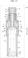
- step S4 in Fig. 8 the liquid 200 accommodated in the first chamber 52 is frozen to obtain a freezing agent 204.
- the freezing agent 204 accommodated in the first chamber 52 is dried (freeze-dried).
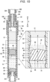
- the syringe outer cylinder 16 on which the distal member 22 is mounted is disposed in a decompression chamber 210 (a vacuum chamber), and an inside of the decompression chamber 210 is decompressed to a state close to vacuum.
- the moisture in the freezing agent 204 is sublimated.
- the sublimated moisture water vapor
- the second concave portions 94 gaps of the distal member 22. Therefore, the moisture of the freezing agent 204 can be efficiently sublimated.
- the freeze-dried agent 12 is obtained.
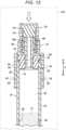
- step S6 in Fig. 8 the distal member 22 with the cap 24 is pushed in the arrow X2 direction in the decompression chamber 210. Accordingly, the first convex portions 64 are separated from the first concave portions 92, and the cylindrical portion 82 slides in the arrow X2 direction with respect to the syringe outer cylinder 16. Then, the first convex portions 64 are fitted into the second concave portions 94, and the second convex portions 66 are fitted into the first concave portions 92. That is, the distal member 22 is displaced from the first state to a second state. At this time, since the packing 90 is inserted into the lumen of the syringe outer cylinder 16 in a liquid-tight manner, the first chamber 52 is sealed by the distal member 22 with the cap 24.
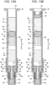
- step S7 in Fig. 8 the liquid agent filling step is performed. Specifically, as shown in Fig. 13A , the syringe outer cylinder 16 is taken out from the decompression chamber 210, and the second chamber 54 is filled with the liquid agent 14 from the proximal opening 36 of the syringe outer cylinder 16 in a state where the syringe outer cylinder 16 is held such that the proximal opening 36 of the syringe outer cylinder 16 faces upward.
- the second gasket 20 is inserted from the proximal opening 36 of the syringe outer cylinder 16.
- the second gasket 20 may be inserted into the syringe outer cylinder 16 by either mechanical plugging or vacuum plugging.
- step S9 in Fig. 8 the finger grip 28 is mounted on the syringe outer cylinder 16, and the plunger 26 is mounted on the second gasket 20 (see Figs. 1 and 2 ). Accordingly, the prefilled syringe 10 is completed.
- a user opens the cap 24 by rotating the cap 24 with respect to the distal member 22.
- the user rotates the cap 24 with one hand while holding the syringe outer cylinder 16 or the finger grip 28 with the other hand.
- the protruding portions 80 of the syringe outer cylinder 16 are inserted into the groove portions 104 of the distal member 22 (see Fig. 6 ), the distal member 22 does not rotate with respect to the syringe outer cylinder 16 together with the cap 24.
- a needle hub 302 of a needle member 300 is mounted on the connection section 88 of the distal member 22.
- the user rotates the proximal operation portion 128 with one hand while holding the finger grip 28 or the syringe outer cylinder 16 with the other hand. Accordingly, since the projection 144 of the plunger engagement portion 136 is screwed to the male screw portion 130 of the plunger body 124 (see Fig. 2 ), the plunger 26 presses the second gasket 20 in the distal direction (the arrow X1 direction) of the syringe outer cylinder 16. Accordingly, the second gasket 20 advances in the arrow X1 direction with respect to the syringe outer cylinder 16.
- the first gasket 18 Since the first gasket 18 is pushed in the distal direction (the arrow X1 direction) of the syringe outer cylinder 16 via the liquid agent 14 in the second chamber 54 when the second gasket 20 advances, the first gasket 18 advances in the arrow X1 direction with respect to the syringe outer cylinder 16.
- the proximal close contact portion 62 of the first gasket 18 is located in the distal direction (the arrow X1 direction) relative to a proximal end of the bypass groove 58, and the distal close contact portion 60 of the first gasket 18 is located in the proximal direction (the arrow X2 direction) relative to a distal end of the bypass groove 58. Accordingly, the liquid agent 14 in the second chamber 54 flows into the first chamber 52 via the plurality of bypass grooves 58.
- the liquid agent 14 in the second chamber 54 is pressed by the second gasket 20 in the distal direction of the syringe outer cylinder 16, and thus smoothly flows into the first chamber 52 via the bypass grooves 58. Thereafter, the second gasket 20 comes into contact with the first gasket 18, and the transition of the liquid agent 14 from the second chamber 54 to the first chamber 52 is completed.
- the user mixes the freeze-dried agent 12 and the liquid agent 14 by shaking the distal portion of the syringe outer cylinder 16 from side to side. Accordingly, the freeze-dried agent 12 is dissolved by the liquid agent 14 to prepare the drug solution M.
- a protective cap 304 (see Fig. 14B ) of the needle member 300 is removed from the needle hub 302, a needle body 306 (see Fig. 14B ) is punctured into a patient (a living body), and the plunger 26 is pressed in the distal direction (the arrow X1 direction) of the syringe outer cylinder 16. Accordingly, the drug solution M in the first chamber 52 is administered to the living body through the lumen 106 of the nozzle 86 and a lumen of the needle body 306. Then, when the first distal slope 44 of the first gasket 18 comes into contact with the slope 114 of the packing 90, all the drug solution M in the first chamber 52 is administered to the living body.
- the present embodiment has the following effects.
- the syringe outer cylinder 16 with the distal member 22 can be put into the decompression chamber 210 in a state (the first state of the distal member 22) in which the distal member 22 is temporarily mounted on the syringe outer cylinder 16.
- the first chamber 52 the accommodation chamber
- the freeze-dried agent 12 can be directly manufactured in the first chamber 52 of the syringe outer cylinder 16.
- the distal member 22 temporarily mounted on the syringe outer cylinder 16 can be brought into the second state to seal the first chamber 52 by the distal member 22. That is, since it is not necessary to attach the distal member 22 to the distal portion of the syringe outer cylinder 16 in the decompression chamber 210, a configuration of a manufacturing device (the decompression chamber 210 and the like) of the prefilled syringe 10 can be simplified.
- the second concave portion 94 is a through-hole, and the gap provided in the distal member 22 is the through-hole.
- the freezing agent 204 in the first state of the distal member 22, can be efficiently sublimated via the through-hole (the second concave portion 94) which is a gap.
- the first engagement portion 68 is provided at the distal portion of the outer peripheral surface of the syringe outer cylinder 16.
- the inner peripheral surface of the cylindrical portion 82 is provided with the second engagement portion 96 that engages with the first engagement portion 68 when the distal member 22 is mounted on the syringe outer cylinder 16.
- One of the first engagement portion 68 and the second engagement portion 96 includes the protruding portion 80.
- the other of the first engagement portion 68 and the second engagement portion 96 includes the groove portion 104 into which the protruding portion 80 is inserted and which extends along the axial direction of the syringe outer cylinder 16.
- the first convex portion 64 and the first concave portion 92 can be positioned in the circumferential direction of the syringe outer cylinder 16.
- the rotation of the distal member 22 with respect to the syringe outer cylinder 16 can be prevented by the protruding portion 80 and the groove portion 104. Accordingly, for example, even when the cap 24 screw-engaged with the distal member 22 is removed, it is possible to prevent the distal member 22 and the cap 24 from rotating together with respect to the syringe outer cylinder 16. Even when the needle member 300 is mounted on the distal member 22 by screw engagement, it is possible to prevent the distal member 22 and a medical device from rotating together with respect to the syringe outer cylinder 16.
- the inner surface of the groove portion 104 has the stopper surface 105 facing the axial direction of the syringe outer cylinder 16.
- the protruding portion 80 abuts to or is close to the stopper surface 105.
- the distal member 22 includes the tubular connection section 88 that covers a distal portion of the nozzle 86 from radially outside.
- the connection section 88 includes the first screw portion 112.
- the cap 24 includes the second screw portion 122 to be screwed to the first screw portion 112, and the sealing member 116 that seals the distal opening of the nozzle 86 in a state in which the second screw portion 122 is fastened to the first screw portion 112.
- the distal opening of the nozzle 86 can be effectively sealed by the sealing member 116 with a simple configuration.
- a proximal portion of the nozzle 86 is located in the lumen of the cylindrical portion 82.
- the distal member 22 includes the annular packing 90 disposed in a liquid-tight manner on the outer peripheral surface of the nozzle 86.
- the packing 90 is inserted into the lumen of the syringe outer cylinder 16 such that the distal opening 34 of the syringe outer cylinder 16 is sealed.
- the first chamber 52 of the syringe outer cylinder 16 can be effectively sealed by the packing 90.
- the proximal surface of the packing 90 has the slope 114 inclined in the distal direction of the nozzle 86 toward the axis of the nozzle 86.
- the distal surface of the first gasket 18 has the first distal slope 44 inclined radially inward toward the distal direction of the syringe outer cylinder 16.
- an amount of the drug solution M remaining in the first chamber 52 when the administration of the drug solution M to the living body is completed can be reduced.
- the first distal slope 44 of the first gasket 18 can come into contact with the entire slope 114 of the packing 90.
- the amount of the drug solution M remaining in the first chamber 52 when the administration of the drug solution M to the living body is completed can be further reduced.
- the prefilled syringe 10 includes the first gasket 18, the second gasket 20, and the plunger 26.
- the second gasket 20 is disposed in the lumen of the syringe outer cylinder 16 in the proximal direction relative to the first gasket 18 and is slidable in the axial direction of the syringe outer cylinder 16.
- the plunger 26 presses the second gasket 20 in the distal direction.
- the second chamber 54 a liquid chamber
- the syringe outer cylinder 16 has the bypass structure 56 for guiding the liquid agent 14 to the first chamber 52.
- the liquid agent 14 is prevented from flowing into the bypass structure 56 by the first gasket 18 in the initial state of the prefilled syringe 10, and is guided to the first chamber 52 when the first gasket 18 moves in the distal direction of the syringe outer cylinder 16 and the first chamber 52 and the second chamber 54 communicate with each other via the bypass structure 56.
- the drug solution M can be obtained by guiding the liquid agent 14 from the second chamber 54 to the first chamber 52 via the bypass structure 56 and mixing the liquid agent 14 and the freeze-dried agent 12 in the first chamber 52.
- the syringe outer cylinder 16 includes the tubular body 30 and the flange portion 32 that protrudes outward in the radial direction from the proximal portion of the body 30 and extends in the circumferential direction.
- the prefilled syringe 10 includes the finger grip 28 that is provided at the proximal portion of the syringe outer cylinder 16 and allows the user to hook fingers thereon.
- the male screw portion 130 is formed on the outer peripheral surface of the plunger 26.
- the flange portion 32 includes the first restriction portion 42.
- the finger grip 28 includes the second restriction portions 142 that restrict the rotation of the finger grip 28 in the circumferential direction with respect to the syringe outer cylinder 16 by abutment of the first restriction portions 42 to the second restriction portions 142, and the plunger engagement portion 136 having the projection 144 to be screwed to the male screw portion 130.
- the plunger 26 moves in the distal direction with respect to the syringe outer cylinder 16 by rotating in the circumferential direction of the syringe outer cylinder 16.
- the plunger 26 can be easily operated by the finger grip 28.
- the first restriction portions 42 and the second restriction portions 142 can prevent the finger grip 28 and the syringe outer cylinder 16 from rotating together when the plunger 26 is rotated.
- the prefilled syringe according to the present invention is not limited to an example including a so-called dual-chamber type syringe outer cylinder including an accommodation chamber (a first chamber) and a liquid chamber (a second chamber).
- the prefilled syringe may include a so-called single-chamber type syringe outer cylinder including an accommodation chamber (a first chamber) and not including a liquid chamber (a second chamber).
- the liquid agent accommodated in the vial can be aspirated (introduced) into the accommodation chamber of the prefilled syringe through the lumen of the nozzle, thereby mixing the freeze-dried agent and the liquid agent.
- the present invention is not limited to the above-described disclosure, and various configurations can be adopted without departing from the gist of the present invention.
Landscapes
- Health & Medical Sciences (AREA)
- Vascular Medicine (AREA)
- Engineering & Computer Science (AREA)
- Anesthesiology (AREA)
- Biomedical Technology (AREA)
- Heart & Thoracic Surgery (AREA)
- Hematology (AREA)
- Life Sciences & Earth Sciences (AREA)
- Animal Behavior & Ethology (AREA)
- General Health & Medical Sciences (AREA)
- Public Health (AREA)
- Veterinary Medicine (AREA)
- Infusion, Injection, And Reservoir Apparatuses (AREA)
Abstract
Description
- The present invention relates to a prefilled syringe, a distal member, a syringe outer cylinder, and a method for manufacturing a prefilled syringe.
- For example,
Japanese Patent No. 6182073 - Incidentally, the above-described prefilled syringe is manufactured, for example, by powdering a freeze-dried agent manufactured in advance in a vial and transferring the powdered freeze-dried agent from the vial to the accommodation chamber of the syringe outer cylinder. However, in this case, it is necessary to transfer the powder agent from the vial to the syringe outer cylinder.
- If the freeze-dried agent can be directly manufactured in the accommodation chamber of the syringe outer cylinder, a powder agent transfer step is not required, which is efficient. To manufacture the freeze-dried agent in the accommodation chamber of the syringe outer cylinder, it is necessary to freeze a liquid agent in a state where the accommodation chamber is filled with the liquid agent, dry (freeze-dry) a freezing agent in a decompression chamber to obtain the freeze-dried agent, and then attach the distal member to the syringe outer cylinder to seal the accommodation chamber. However, in this case, it is necessary to provide a large attachment device in the decompression chamber for attaching the distal member to the syringe outer cylinder, which is not realistic. Note that, if the distal member is mounted on the syringe outer cylinder and the accommodation chamber is sealed in advance before the syringe outer cylinder is placed in the decompression chamber, the freezing agent cannot be sublimated during freeze-drying.
- An object of the present invention is to solve the above-described problems.
-
- (1) A first aspect of the present invention is a prefilled syringe including a syringe outer cylinder, a gasket slidably disposed in the syringe outer cylinder, a freeze-dried agent accommodated in an accommodation chamber of the syringe outer cylinder, a distal member mounted on a distal portion of the syringe outer cylinder, and a cap configured to be attached to and detached from the distal member, in which the distal member includes a cylindrical portion into which the distal portion of the syringe outer cylinder is inserted, and a nozzle located inside the cylindrical portion and having a lumen communicating with the accommodation chamber, the cap seals a distal opening of the nozzle in a state of being mounted on the distal member, a first convex portion and a second convex portion located in a proximal direction of the syringe outer cylinder relative to the first convex portion are provided on a distal portion of an outer peripheral surface of the syringe outer cylinder, a first concave portion and a second concave portion located in a distal direction of the syringe outer cylinder relative to the first concave portion are provided in an inner peripheral surface of the cylindrical portion, a displacement of the distal member from a first state in which the distal member is temporarily mounted on the distal portion of the syringe outer cylinder to a second state in which the accommodation chamber is sealed by the distal member is completed, the first state is a state in which the first convex portion is fitted into the first concave portion and the accommodation chamber is in communication with an outside via a gap between the syringe outer cylinder and the cylindrical portion or a gap provided in the distal member, and the second state is a state in which the first convex portion is fitted into the second concave portion and the second convex portion is fitted into the first concave portion.
- (2) The prefilled syringe according to item (1), in which the second concave portion is a through-hole, and the gap provided in the distal member is the through-hole.
- (3) The prefilled syringe according to the item (1) or (2), in which a first engagement portion is provided on the distal portion of the outer peripheral surface of the syringe outer cylinder, a second engagement portion configured to engage with the first engagement portion when the distal member is mounted on the syringe outer cylinder is provided in the inner peripheral surface of the cylindrical portion, one of the first engagement portion and the second engagement portion includes a protruding portion, and the other of the first engagement portion and the second engagement portion includes a groove portion that is configured to allow the protruding portion to be inserted therein and that extends along an axial direction of the syringe outer cylinder.
- (4) The prefilled syringe according to item (3), in which an inner surface of the groove portion has a stopper surface that faces the axial direction of the syringe outer cylinder, and the protruding portion is abutted to or close to the stopper surface.
- (5) The prefilled syringe according to any one of items (1) to (4), in which the distal member includes a tubular connection section that covers a distal portion of the nozzle from radially outside, the connection section includes a first screw portion, and the cap includes a second screw portion to be screwed to the first screw portion, and a sealing member configured to seal the distal opening of the nozzle in a state in which the second screw portion is fastened to the first screw portion.
- (6) The prefilled syringe according to any one of items (1) to (5), in which a proximal portion of the nozzle is located in a lumen of the cylindrical portion, the distal member includes an annular packing disposed in a liquid-tight manner on an outer peripheral surface of the nozzle, and the packing is inserted into a lumen of the syringe outer cylinder to seal a distal opening of the syringe outer cylinder.
- (7) The prefilled syringe according to item (6), in which a proximal surface of the packing has a slope inclined in a distal direction of the nozzle toward an axis of the nozzle, and a distal surface of the gasket has a distal slope inclined radially inward toward the distal direction of the syringe outer cylinder.
- (8) The prefilled syringe according to item (7), in which the distal slope of the gasket is configured to come into contact with the entire slope of the packing.
- (9) The prefilled syringe according to any one of items (1) to (8), in which the gasket is a first gasket, the prefilled syringe includes a second gasket that is disposed in a proximal direction relative to the first gasket in the lumen of the syringe outer cylinder and that is configured to slide in the axial direction of the syringe outer cylinder, and a plunger configured to press the second gasket in a distal direction, in an initial state of the prefilled syringe, a liquid chamber filled with a liquid agent is formed between the first gasket and the second gasket, the syringe outer cylinder has a bypass structure configured to guide the liquid agent to the accommodation chamber, and the liquid agent is prevented from flowing into the bypass structure by the first gasket in the initial state of the prefilled syringe, and is guided to the accommodation chamber by movement of the first gasket in the distal direction of the syringe outer cylinder and the accommodation chamber and the liquid chamber communicating with each other via the bypass structure.
- (10) The prefilled syringe according to item (9), in which the syringe outer cylinder includes a tubular body, and a flange portion protruding radially outward from a proximal portion of the tubular body and extending in a circumferential direction, the prefilled syringe includes a finger grip provided on a proximal portion of the syringe outer cylinder and configured to allow a user to hook a finger thereon, a male screw portion is formed on an outer peripheral surface of the plunger, the flange portion includes a first restriction portion, the finger grip includes a second restriction portion configured to restrict rotation of the syringe outer cylinder in a circumferential direction with respect to the syringe outer cylinder by abutment of the first restriction portion to the second restriction portion, and a plunger engagement portion having a projection to be screwed to the male screw portion, and the plunger moves in the distal direction with respect to the syringe outer cylinder by rotating in a circumferential direction of the finger grip.
- (11) A second aspect of the present invention is a distal member of a prefilled syringe, in which the prefilled syringe includes a syringe outer cylinder, a gasket slidably disposed in the syringe outer cylinder, a freeze-dried agent accommodated in an accommodation chamber of the syringe outer cylinder, and a cap configured to be attached to and detached from the distal member, a first convex portion and a second convex portion located in a proximal direction of the syringe outer cylinder relative to the first convex portion are provided on a distal portion of an outer peripheral surface of the syringe outer cylinder, the distal member includes a cylindrical portion into which the distal portion of the syringe outer cylinder is inserted, and a nozzle located inside the cylindrical portion and having a lumen communicating with the accommodation chamber, in which the cap seals a distal opening of the nozzle in a state of being mounted on the distal member, a first concave portion and a second concave portion located in a distal direction of the syringe outer cylinder relative to the first concave portion are provided in an inner peripheral surface of the cylindrical portion, a displacement of the distal member from a first state in which the distal member is temporarily mounted on the distal portion of the syringe outer cylinder to a second state in which the accommodation chamber is sealed by the distal member is completed, the first state is a state in which the first convex portion is fitted into the first concave portion and the accommodation chamber is in communication with an outside via a gap between the syringe outer cylinder and the cylindrical portion or a gap provided in the distal member, and the second state is a state in which the first convex portion is fitted into the second concave portion and the second convex portion is fitted into the first concave portion.
- (12) A third aspect of the present invention is a syringe outer cylinder of a prefilled syringe, in which the prefilled syringe includes a distal member mounted on a distal portion of the syringe outer cylinder, a gasket slidably disposed in the syringe outer cylinder, a freeze-dried agent accommodated in an accommodation chamber of the syringe outer cylinder, and a cap configured to be attached to and detached from the distal member, the distal member includes a cylindrical portion into which the distal portion of the syringe outer cylinder is inserted, and a nozzle located inside the cylindrical portion and having a lumen communicating with the accommodation chamber, the cap seals a distal opening of the nozzle in a state of being mounted on the distal member, a first concave portion and a second concave portion located in a distal direction of the syringe outer cylinder relative to the first concave portion are provided in an inner peripheral surface of the cylindrical portion, a first convex portion and a second convex portion located in a proximal direction of the syringe outer cylinder relative to the first convex portion are provided on a distal portion of an outer peripheral surface of the syringe outer cylinder, a displacement of the distal member from a first state in which the distal member is temporarily mounted on the distal portion of the syringe outer cylinder to a second state in which the accommodation chamber is sealed by the distal member is completed, the first state is a state in which the first convex portion is fitted into the first concave portion and the accommodation chamber is in communication with an outside via a gap between the syringe outer cylinder and the cylindrical portion or a gap provided in the distal member, and the second state is a state in which the first convex portion is fitted into the second concave portion and the second convex portion is fitted into the first concave portion.
- (13) A fourth aspect of the present invention is a method for manufacturing a prefilled syringe, and the method includes: an insertion step of inserting a gasket into a syringe outer cylinder; a liquid accommodation step of filling an accommodation chamber communicating with a distal opening of the syringe outer cylinder with a liquid after the insertion step; a temporary mounting step of temporarily mounting a distal member on a distal portion of the syringe outer cylinder such that the accommodation chamber communicates with an outside; a freezing step of freezing the liquid in the accommodation chamber of the syringe outer cylinder on which the distal member is temporarily mounted to obtain a freezing agent; a drying step of drying the freezing agent in a decompression chamber to obtain a freeze-dried agent; and a sealing step of sealing the accommodation chamber by blocking communication between the accommodation chamber and the outside by pushing the distal member into the syringe outer cylinder after the drying step.
- (14) The method for manufacturing a prefilled syringe according to item (13), in which the distal member includes a cylindrical portion configured to allow the distal portion of the syringe outer cylinder to be inserted therein, and a nozzle located inside the cylindrical portion and having a lumen communicating with the accommodation chamber, a distal opening of the nozzle is sealed by a cap mounted on the distal member, a first convex portion and a second convex portion located in a proximal direction of the syringe outer cylinder relative to the first convex portion are provided on a distal portion of an outer peripheral surface of the syringe outer cylinder, a first concave portion and a second concave portion located in a distal direction of the syringe outer cylinder relative to the first concave portion are provided in an inner peripheral surface of the cylindrical portion, in the temporary mounting step, in a state in which the first convex portion is fitted into the first concave portion, the accommodation chamber communicates with the outside via a gap between the syringe outer cylinder and the cylindrical portion or a gap provided in the distal member, and in the sealing step, the first convex portion is fitted into the second concave portion, and the second convex portion is fitted into the first concave portion.
- According to the present invention, the syringe outer cylinder with the distal member can be put into the decompression chamber in a state (the first state of the distal member) in which the distal member is temporarily mounted on the syringe outer cylinder. In the first state of the distal member, the accommodation chamber communicates with the outside via a gap. Therefore, since the freezing agent in the accommodation chamber of the syringe outer cylinder can be sublimated when the freezing agent is dried (freeze-dried), the freeze-dried agent can be directly manufactured in the accommodation chamber of the syringe outer cylinder. After the completion of the freeze-drying, the distal member temporarily mounted on the syringe outer cylinder can be brought into the second state to seal the accommodation chamber by the distal member. That is, since it is not necessary to attach the distal member to the distal portion of the syringe outer cylinder in the decompression chamber, a configuration of a manufacturing device (the decompression chamber and the like) of the prefilled syringe can be simplified.
-
- [
Fig. 1] Fig. 1 is a perspective view of a prefilled syringe according to an embodiment of the invention. - [
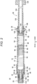
Fig. 2] Fig. 2 is a longitudinal cross-sectional view of the prefilled syringe inFig. 1 . - [
Fig. 3] Fig. 3 is an exploded perspective view of a distal portion of the prefilled syringe inFig. 1 . - [
Fig. 4] Fig. 4 is an enlarged view of the distal portion of the prefilled syringe inFig. 2 . - [
Fig. 5] Fig. 5 is a longitudinal cross-sectional view taken along a line V-V inFig. 4 . - [
Fig. 6] Fig. 6 is a cross-sectional view taken along a line VI-VI inFig. 4 . - [
Fig. 7] Fig. 7 is a cross-sectional view of a flange portion of the prefilled syringe inFig. 2 . - [
Fig. 8] Fig. 8 is a flowchart showing a method for manufacturing the prefilled syringe inFig. 1 . - [
Fig. 9A] Fig. 9A is a cross-sectional view showing a first insertion step. - [
Fig. 9B] Fig. 9B is a cross-sectional view showing a liquid accommodation step. - [
Fig. 10] Fig. 10 is a cross-sectional view of a temporary mounting step. - [
Fig. 11] Fig. 11 is a cross-sectional view showing a drying step. - [
Fig. 12] Fig. 12 is a cross-sectional view showing a sealing step. - [
Fig. 13A] Fig. 13A is a cross-sectional view of a liquid agent filling step. - [
Fig. 13B] Fig. 13B is a cross-sectional view showing a second insertion step. - [
Fig. 14A] Fig. 14A is a diagram showing a state in which a cap of the prefilled syringe is removed. - [
Fig. 14B] Fig. 14B is a diagram showing a state in which a needle member is mounted on the distal member. - [
Fig. 15] Fig. 15 is a cross-sectional view showing a state in which a liquid agent is introduced into an accommodation chamber. - [
Fig. 16] Fig. 16 is a cross-sectional view showing a state in which rotation of a plunger is restricted. - [
Fig. 17] Fig. 17 is a cross-sectional view showing a state in which a drug solution is delivered to a living body. - As shown in
Figs. 1 and2 , aprefilled syringe 10 according to an embodiment of the invention is a mixing device that mixes a freeze-driedagent 12 and a liquid agent 14 (a dissolving agent) to obtain a drug solution M (seeFig. 17 ). - The
prefilled syringe 10 includes a syringeouter cylinder 16, afirst gasket 18, asecond gasket 20, adistal member 22, acap 24, aplunger 26, and afinger grip 28. In the following description, an axial direction of theprefilled syringe 10 may be referred to as an arrow X direction, a distal direction of theprefilled syringe 10 may be referred to as an arrow X1 direction, and a proximal direction of theprefilled syringe 10 may be referred to as an arrow X2 direction. - The syringe
outer cylinder 16 is integrally formed of a hard resin material. The syringeouter cylinder 16 has transparency such that an inside thereof can be visually recognized from an outside. The syringeouter cylinder 16 includes abody 30 and aflange portion 32. Thebody 30 extends along the axial direction (the arrow X direction) of theprefilled syringe 10. Thebody 30 is formed in a cylindrical shape and has a lumen extending from adistal opening 34 of the syringeouter cylinder 16 to aproximal opening 36 of the syringeouter cylinder 16. - As shown in
Fig. 7 , theflange portion 32 protrudes outward in a radial direction from a proximal portion of thebody 30 and extends in an annular shape. A pair offirst restriction portions 42 are provided on a protruding end surface (an outer peripheral surface) of theflange portion 32. Thefirst restriction portion 42 is a flat surface. The pair offirst restriction portions 42 face in opposite directions. - In
Fig. 2 , thefirst gasket 18 is slidably disposed in the lumen of the syringeouter cylinder 16. Thefirst gasket 18 is formed of, for example, an elastic resin material such as a rubber material or an elastomer material. An outer peripheral surface of thefirst gasket 18 is in close contact with an inner peripheral surface of thebody 30 in a liquid-tight manner. In an initial state of theprefilled syringe 10, thefirst gasket 18 is located in the middle of thebody 30 in the axial direction. - A distal surface (a surface facing the arrow X1 direction) of the
first gasket 18 has a firstdistal slope 44 inclined radially inward in a tapered shape toward the distal direction of the syringeouter cylinder 16. A proximal surface (a surface facing the arrow X2 direction) of thefirst gasket 18 has aproximal slope 46 inclined radially inward in a tapered shape toward the distal direction of the syringeouter cylinder 16. - The
second gasket 20 is slidably disposed in the lumen of the syringeouter cylinder 16. Thesecond gasket 20 is located in the proximal direction (the arrow X2 direction) of the syringeouter cylinder 16 with respect to thefirst gasket 18. Thesecond gasket 20 is formed of the same material as thefirst gasket 18. An outer peripheral surface of thesecond gasket 20 is in close contact with the inner peripheral surface of thebody 30 in a liquid-tight manner. In the initial state of theprefilled syringe 10, thesecond gasket 20 is located at the proximal portion of thebody 30. - A distal surface (a surface facing the arrow X1 direction) of the
second gasket 20 has a seconddistal slope 48 inclined radially inward in a tapered shape toward the distal direction of the syringeouter cylinder 16. A taper angle of the seconddistal slope 48 of thesecond gasket 20 is the same (substantially the same) as a taper angle of theproximal slope 46 of thefirst gasket 18. A connectionconcave portion 50 for connecting theplunger 26 is formed in a proximal surface of thesecond gasket 20. - In the initial state of the
prefilled syringe 10, the syringeouter cylinder 16 has afirst chamber 52 located in the distal direction (the arrow X1 direction) with respect to thefirst gasket 18 and asecond chamber 54 located in the proximal direction (the arrow X2 direction) with respect to thefirst gasket 18. Thefirst chamber 52 is formed between thedistal member 22 attached to a distal portion of the syringeouter cylinder 16 and thefirst gasket 18. Thefirst chamber 52 is an accommodation chamber for accommodating the freeze-driedagent 12. - The
second chamber 54 is formed between thefirst gasket 18 and thesecond gasket 20. Thesecond chamber 54 is a liquid chamber for accommodating theliquid agent 14 for dissolving the freeze-driedagent 12. In the initial state of theprefilled syringe 10, thefirst chamber 52 and thesecond chamber 54 are partitioned by thefirst gasket 18 without communicating with each other. - The syringe
outer cylinder 16 has abypass structure 56 for communicating thefirst chamber 52 and thesecond chamber 54 with each other. Thebypass structure 56 includes a plurality ofbypass grooves 58 formed in the inner peripheral surface of thebody 30. The plurality ofbypass grooves 58 is arranged at intervals in a circumferential direction of thebody 30. Eachbypass groove 58 extends linearly along the axial direction (the arrow X direction) of thebody 30. A length of eachbypass groove 58 along the arrow X direction is larger than a length of a portion of thefirst gasket 18 in close contact with the inner peripheral surface of thebody 30 along the arrow X direction (a distance from a distalclose contact portion 60 to a proximal close contact portion 62). - The number, position, size, shape, and the like of the
bypass grooves 58 can be appropriately set. Thebypass structure 56 is not limited to a structure including the plurality ofbypass grooves 58. For example, a concave bypass flow path may be formed in an inner surface of thebody 30 by causing a part of thebody 30 to bulge outward in the radial direction. - As shown in
Figs. 3 to 6 , two firstconvex portions 64, two secondconvex portions 66, and twofirst engagement portions 68 protrude from a distal portion of an outer peripheral surface of thebody 30. InFigs. 3 and4 , the firstconvex portion 64 extends along the circumferential direction of thebody 30. - As shown in
Fig. 4 , the firstconvex portion 64 has a triangular cross section along an axis of the syringeouter cylinder 16. The firstconvex portion 64 has afirst slope 70 and afirst stopper surface 72. Thefirst slope 70 is inclined inward from a protruding end of the firstconvex portion 64 toward the distal direction (the arrow X1 direction) of the syringeouter cylinder 16. Thefirst stopper surface 72 is a flat surface along a direction orthogonal to the axis of the syringeouter cylinder 16, and faces the proximal direction (the arrow X2 direction) of the syringeouter cylinder 16. - In
Figs. 3 and4 , the two firstconvex portions 64 are disposed at an interval in the circumferential direction of thebody 30. The two firstconvex portions 64 are located 180° apart in the circumferential direction of thebody 30. The two firstconvex portions 64 are located at the same position without being displaced from each other in the axial direction of the syringeouter cylinder 16. - A shape and a size of the second
convex portion 66 are the same as (substantially the same as) a shape and a size of the firstconvex portion 64. However, the shape and the size of the secondconvex portion 66 may be different from the shape and the size of the firstconvex portion 64. - In
Figs. 3 and6 , the secondconvex portion 66 extends along the circumferential direction of thebody 30. As shown inFig. 4 , the secondconvex portion 66 has a triangular cross section along the axis of the syringeouter cylinder 16. The secondconvex portion 66 has asecond slope 74 and asecond stopper surface 76. Thesecond slope 74 is inclined inward from a protruding end of the secondconvex portion 66 toward the distal direction (the arrow X1 direction) of the syringeouter cylinder 16. Thesecond stopper surface 76 is a flat surface along the direction orthogonal to the axis of the syringeouter cylinder 16, and faces the proximal direction (the arrow X2 direction) of the syringeouter cylinder 16. - As shown in
Figs. 3 ,4 , and6 , the two secondconvex portions 66 are disposed at an interval in the circumferential direction of thebody 30. Specifically, the two secondconvex portions 66 are located 180° apart in the circumferential direction of thebody 30. The two secondconvex portions 66 are located at the same position without being displaced from each other in the axial direction of the syringeouter cylinder 16. The two secondconvex portions 66 are located at the same positions as the two firstconvex portions 64 in the circumferential direction of thebody 30. The secondconvex portion 66 is located in the arrow X2 direction with respect to the firstconvex portion 64. - In
Figs. 3 ,5 , and6 , thefirst engagement portion 68 includes a protrudingportion 80 protruding outward in the radial direction from the outer peripheral surface of thebody 30. The protrudingportion 80 extends along the axial direction of the syringe outer cylinder 16 (the body 30). A length of the protrudingportion 80 along the circumferential direction of thebody 30 is less than a length of each of the firstconvex portion 64 and the secondconvex portion 66 along the circumferential direction of thebody 30. As shown inFig. 3 , a distal end (an end in the arrow X1 direction) of the protrudingportion 80 is located in the arrow X1 direction with respect to the secondconvex portion 66 and in the arrow X2 direction with respect to the firstconvex portion 64. A proximal end (an end in the arrow X2 direction) of the protrudingportion 80 is located in the arrow X2 direction with respect to the secondconvex portion 66. - In
Figs. 5 and6 , the twofirst engagement portions 68 are disposed at an interval in the circumferential direction of thebody 30. The twofirst engagement portions 68 are located 180° apart in the circumferential direction of thebody 30. The twofirst engagement portions 68 are located at the same position without being displaced from each other in the axial direction of the syringeouter cylinder 16. Thefirst engagement portion 68 is located between the two secondconvex portions 66. Thefirst engagement portion 68 is located at a position shifted from the secondconvex portion 66 by 90° in the circumferential direction of thebody 30. - As shown in
Figs. 3 and4 , thedistal member 22 includes acylindrical portion 82, anannular wall portion 84, anozzle 86, aconnection section 88, and a packing 90. Thecylindrical portion 82, theannular wall portion 84, thenozzle 86, and theconnection section 88 are integrally formed of a hard resin material. Thecylindrical portion 82 is formed in a cylindrical shape. The distal portion of the syringe outer cylinder 16 (the body 30) is inserted into thecylindrical portion 82. Thecylindrical portion 82 is formed with two firstconcave portions 92, two secondconcave portions 94, and twosecond engagement portions 96. - In
Figs. 3 and6 , the firstconcave portion 92 extends along a circumferential direction of thecylindrical portion 82. A length of the firstconcave portion 92 along the circumferential direction of thecylindrical portion 82 is slightly larger than a length of each of the firstconvex portion 64 and the secondconvex portion 66 along the circumferential direction of thebody 30. The firstconcave portion 92 is a rectangular hole penetrating a wall portion of thecylindrical portion 82. However, the firstconcave portion 92 may be a recess having a bottom portion formed on an inner peripheral surface of thecylindrical portion 82. The firstconcave portion 92 is formed such that the secondconvex portion 66 can be fitted thereto. The firstconcave portion 92 is formed such that the firstconvex portion 64 can be fitted thereto (seeFig. 10 ). - An inner surface of the first
concave portion 92 has a firstabutting surface 100 to which thesecond stopper surface 76 can abut. The firstabutting surface 100 is a flat surface orthogonal to the axial direction (the arrow X direction) of thecylindrical portion 82. The firstabutting surface 100 faces the arrow X1 direction. - In
Fig. 6 , the two firstconcave portions 92 are disposed at an interval in the circumferential direction of thecylindrical portion 82. The two firstconcave portions 92 are located 180° apart in the circumferential direction of thecylindrical portion 82. The two firstconcave portions 92 are located at the same position without being displaced from each other in the axial direction (the arrow X direction) of thecylindrical portion 82. - As shown in
Figs. 3 and4 , a shape and a size of the secondconcave portion 94 are the same (substantially the same) as a shape and a size of the above-described firstconcave portion 92 penetrating the wall portion of thecylindrical portion 82. However, the shape and the size of the secondconcave portion 94 may be different from the shape and the size of the firstconcave portion 92. - The second
concave portion 94 extends along the circumferential direction of thecylindrical portion 82. The size, the shape, and the position of the secondconcave portion 94 are formed such that the firstconvex portion 64 can be fitted thereto. A length of the secondconcave portion 94 along the circumferential direction of thecylindrical portion 82 is slightly larger than the length of the firstconvex portion 64 along the circumferential direction of thebody 30. The secondconcave portion 94 is a rectangular through-hole. However, the secondconcave portion 94 may be a recess having a bottom portion formed on an inner peripheral surface of thecylindrical portion 82. The secondconcave portion 94 is formed such that the firstconvex portion 64 can be fitted thereto. - An inner surface of the second
concave portion 94 has a secondabutting surface 102 to which thefirst stopper surface 72 can abut. The secondabutting surface 102 is a flat surface orthogonal to the axial direction (the arrow X direction) of thecylindrical portion 82. The secondabutting surface 102 faces the arrow X1 direction. - The two second
concave portions 94 are disposed at an interval in the circumferential direction of thecylindrical portion 82. The two secondconcave portions 94 are located 180° apart in the circumferential direction of thecylindrical portion 82. The two secondconcave portions 94 are located at the same position without being displaced from each other in the axial direction (the arrow X direction) of thecylindrical portion 82. The two secondconcave portions 94 are located at the same positions as the two firstconcave portions 92 in the circumferential direction of thecylindrical portion 82. The secondconcave portion 94 is located at an interval from the firstconcave portion 92 in the arrow X1 direction. - In
Figs. 3 ,5 , and6 , thesecond engagement portion 96 includes agroove portion 104 formed in the inner peripheral surface of thecylindrical portion 82 and astopper surface 105. Thegroove portion 104 is formed by the wall portion of thecylindrical portion 82 protruding outward in the radial direction. Therefore, a portion of thecylindrical portion 82 in which thegroove portion 104 is formed is not thinned. Thegroove portion 104 extends along the axial direction of thecylindrical portion 82. - The
groove portion 104 extends to a proximal end of thecylindrical portion 82. A shape and a size of thegroove portion 104 are formed such that the protrudingportion 80 can be inserted. Thestopper surface 105 is a surface facing a proximal direction (the arrow X2 direction) of thecylindrical portion 82 in an inner surface of thegroove portion 104. Thestopper surface 105 is abutted to or close to the distal end of the protrudingportion 80. - As shown in
Figs. 5 and6 , the twosecond engagement portions 96 are disposed at an interval in the circumferential direction of thecylindrical portion 82. The twosecond engagement portions 96 are located 180° apart in the circumferential direction of thecylindrical portion 82. The twosecond engagement portions 96 are located at the same position without being displaced from each other in the axial direction of the syringeouter cylinder 16. - In
Figs. 3 and4 , theannular wall portion 84 protrudes inward in the radial direction from a distal portion of thecylindrical portion 82 and extends in an annular shape. As shown inFig. 4 , thenozzle 86 is connected to a radially inward end portion (inner end portion) of theannular wall portion 84. Thenozzle 86 extends along the axial direction (the arrow X direction) of thecylindrical portion 82. - The
nozzle 86 is located inside thecylindrical portion 82 to be coaxial with thecylindrical portion 82. Thenozzle 86 includes alumen 106 extending from a distal end to a proximal end of thenozzle 86. Thelumen 106 of thenozzle 86 communicates with thefirst chamber 52 of thebody 30. Thenozzle 86 includes adistal nozzle portion 108 protruding in the arrow X1 direction from an inner peripheral end portion of theannular wall portion 84 and aproximal nozzle portion 110 protruding in the arrow X2 direction from the inner peripheral end portion of theannular wall portion 84. An outer peripheral surface of thedistal nozzle portion 108 is diameter-reduced in a tapered shape toward the arrow X1 direction. - In
Figs. 3 and4 , theconnection section 88 protrudes from theannular wall portion 84 in the arrow X1 direction and extends in an annular shape. A protruding end of theconnection section 88 is located in the arrow X2 direction with respect to a protruding end of thedistal nozzle portion 108. A space is formed between an inner peripheral surface of theconnection section 88 and an outer peripheral surface of thedistal nozzle portion 108. Afirst screw portion 112 is formed in the inner peripheral surface of theconnection section 88. Thefirst screw portion 112 is a female screw portion. - In
Fig. 4 , the packing 90 is formed of, for example, an elastic resin material such as a rubber material or an elastomer material. The packing 90 is disposed on a surface of theannular wall portion 84 that faces the arrow X2 direction. The packing 90 is in contact with an outer peripheral surface of theproximal nozzle portion 110 in a liquid-tight manner and extends in an annular shape. A proximal surface (a surface facing the arrow X2 direction) of the packing 90 has aslope 114 inclined in a distal direction of thenozzle 86 toward an axis of thenozzle 86. Theslope 114 is located in the arrow X2 direction with respect to a protruding end (an end in the arrow X2 direction) of theproximal nozzle portion 110. - As shown in
Figs. 3 and4 , thecap 24 includes a sealingmember 116 and acap body 118. The sealingmember 116 is formed of a soft rubber material. The sealingmember 116 seals a distal opening of thenozzle 86. InFig. 4 , the sealingmember 116 is formed with an insertionconcave portion 120 opened in the arrow X2 direction. Thedistal nozzle portion 108 is fitted into the insertionconcave portion 120 in liquid-tight and air-tight manners. - The
cap body 118 is formed of a hard resin material. Thecap body 118 is formed in an annular shape. The sealingmember 116 is disposed in a lumen of thecap body 118. Thecap body 118 locks the sealingmember 116. Asecond screw portion 122 that is screwed to thefirst screw portion 112 of theconnection section 88 is formed in an outer peripheral surface of a proximal portion (an end portion in the arrow X2 direction) of thecap body 118. Thesecond screw portion 122 is a male screw portion. That is, thecap body 118 is screw-engaged with thedistal member 22. - As shown in
Figs. 1 and2 , theplunger 26 extends along the axial direction of the syringeouter cylinder 16. Theplunger 26 is integrally formed of a hard resin material. Theplunger 26 includes aplunger body 124, adistal connection section 126, and aproximal operation portion 128. - In
Fig. 2 , theplunger body 124 is formed in a cylindrical shape. Theplunger body 124 may be formed solid. An outer diameter of theplunger body 124 is less than an inner diameter of thebody 30. As shown inFig. 1 , amale screw portion 130 and arotation restriction portion 132 are provided in an outer peripheral surface of theplunger body 124. Therotation restriction portion 132 is connected to an end portion of themale screw portion 130 in the arrow X2 direction. Therotation restriction portion 132 protrudes outward in the radial direction from the outer peripheral surface of theplunger body 124. Therotation restriction portion 132 extends along an axial direction of theplunger body 124. - In
Fig. 2 , thedistal connection section 126 protrudes from a distal portion of theplunger body 124 in the distal direction (the arrow X1 direction). An outer diameter of thedistal connection section 126 is less than the outer diameter of theplunger body 124. Thedistal connection section 126 is screw-engaged with thesecond gasket 20 in a state of being inserted into the connectionconcave portion 50 of thesecond gasket 20. - The
proximal operation portion 128 protrudes outward in the radial direction from a proximal portion of theplunger body 124 and is formed in an annular shape. Theproximal operation portion 128 has a size and a shape that allow an easy manual operation. An outer diameter of theproximal operation portion 128 is larger than an outer diameter of thebody 30. - As shown in
Figs. 1 and2 , thefinger grip 28 is provided at a proximal portion of the syringeouter cylinder 16. Thefinger grip 28 includes a mountingportion 134, aplunger engagement portion 136, and a pair offinger rest portions 138. InFig. 7 , aninsertion hole 140 into which theflange portion 32 of the syringeouter cylinder 16 is inserted is formed in the mountingportion 134. A pair ofsecond restriction portions 142 facing thefirst restriction portions 42 of theflange portion 32 are provided in an inner surface of theinsertion hole 140. The pair ofsecond restriction portions 142 are flat surfaces. When thefirst restriction portions 42 abut to thesecond restriction portions 142, thefinger grip 28 and the syringeouter cylinder 16 are prevented from relatively rotating in the circumferential direction of theplunger body 124. - The numbers, shapes, positions, sizes, and the like of the
first restriction portions 42 and thesecond restriction portions 142 can be appropriately set. - In
Figs. 2 and16 , theplunger engagement portion 136 protrudes from the mountingportion 134 in a cylindrical shape in the arrow X2 direction. In an inner peripheral surface of theplunger engagement portion 136, aprojection 144 to be screwed with themale screw portion 130 of theplunger 26 is provided. Theprojection 144 extends by a length less than 360° along the helix of themale screw portion 130 of theplunger 26. - As shown in
Fig. 1 , the pair offinger rest portions 138 extend in opposite directions from the mountingportion 134. Thefinger rest portions 138 extend in a flat plate shape. - Next, a method for manufacturing the above-described
prefilled syringe 10 will be described. As shown inFig. 8 , the method for manufacturing theprefilled syringe 10 includes a first insertion step, a liquid accommodation step, a temporary mounting step, a freezing step, a drying step, a sealing step, a liquid agent filling step, a second insertion step, and a mounting step. - First, in the first insertion step (step S1), as shown in
Fig. 9A , thefirst gasket 18 is inserted into the lumen of the syringeouter cylinder 16. At this time, thefirst gasket 18 is located in the proximal direction of the syringeouter cylinder 16 relative to thebypass structure 56. - Subsequently, in the liquid accommodation step (step S2 in
Fig. 8 ), as shown inFig. 9B , a liquid 200 is accommodated in thefirst chamber 52 of the syringeouter cylinder 16. At this time, the syringeouter cylinder 16 is held in an upright state such that thedistal opening 34 of the syringeouter cylinder 16 faces upward. - Next, in the temporary mounting step (step S3 in
Fig. 8 ), as shown inFig. 10 , thedistal member 22 with thecap 24 is temporarily mounted on the distal portion of the syringeouter cylinder 16. That is, thedistal member 22 is attached from above the syringeouter cylinder 16 such that the distal portion of the syringeouter cylinder 16 is inserted from a proximal opening of thecylindrical portion 82. At this time, the two protrudingportions 80 are inserted into the twogroove portions 104, thereby positioning the firstconvex portions 64 and the firstconcave portions 92 in the circumferential direction of thecylindrical portion 82. - Thereafter, when the
distal member 22 with thecap 24 is pressed against the syringeouter cylinder 16, thecylindrical portion 82 moves downward with respect to the syringeouter cylinder 16, and the firstconvex portions 64 are fitted into the firstconcave portions 92. Accordingly, the temporary mounting of thedistal member 22 to the distal portion of the syringeouter cylinder 16 is completed. In a first state of thedistal member 22 in which thedistal member 22 is temporarily mounted on the syringeouter cylinder 16, a distal end of the syringeouter cylinder 16 is located in the arrow X2 direction relative to a proximal end of the packing 90. In the first state of thedistal member 22, thefirst chamber 52 of the syringeouter cylinder 16 communicates with an outside via the second concave portions 94 (through-holes) which are gaps. - Note that, when the second
concave portion 94 is not a through-hole but a bottomed recess, thefirst chamber 52 of the syringeouter cylinder 16 may communicate with the outside via a gap (including the groove portions 104) between the syringeouter cylinder 16 and thecylindrical portion 82 in the first state of thedistal member 22. When the secondconcave portion 94 is not a through-hole but a bottomed recess and thedistal member 22 is provided with a through-hole different from the secondconcave portion 94, thefirst chamber 52 of the syringeouter cylinder 16 may communicate with the outside via the through-hole different from the secondconcave portion 94 in the first state of thedistal member 22. In this case, in the first state of thedistal member 22, when the through-hole is located in the distal direction (the arrow X1 direction) relative to the distal end of the syringeouter cylinder 16, the through-hole can be prevented from being blocked by the syringeouter cylinder 16. - Thereafter, in the freezing step (step S4 in
Fig. 8 ), the liquid 200 accommodated in thefirst chamber 52 is frozen to obtain a freezingagent 204. - Subsequently, in the drying step (step S5), the freezing
agent 204 accommodated in thefirst chamber 52 is dried (freeze-dried). Specifically, as shown inFig. 11 , the syringeouter cylinder 16 on which thedistal member 22 is mounted is disposed in a decompression chamber 210 (a vacuum chamber), and an inside of thedecompression chamber 210 is decompressed to a state close to vacuum. Accordingly, since a boiling point of the freezingagent 204 becomes lower than that at the atmospheric pressure, the moisture in the freezingagent 204 is sublimated. At this time, the sublimated moisture (water vapor) is discharged to the outside through the second concave portions 94 (gaps) of thedistal member 22. Therefore, the moisture of the freezingagent 204 can be efficiently sublimated. By this drying step, the freeze-driedagent 12 is obtained. - Next, in the sealing step (step S6 in
Fig. 8 ), as shown inFig. 12 , thedistal member 22 with thecap 24 is pushed in the arrow X2 direction in thedecompression chamber 210. Accordingly, the firstconvex portions 64 are separated from the firstconcave portions 92, and thecylindrical portion 82 slides in the arrow X2 direction with respect to the syringeouter cylinder 16. Then, the firstconvex portions 64 are fitted into the secondconcave portions 94, and the secondconvex portions 66 are fitted into the firstconcave portions 92. That is, thedistal member 22 is displaced from the first state to a second state. At this time, since the packing 90 is inserted into the lumen of the syringeouter cylinder 16 in a liquid-tight manner, thefirst chamber 52 is sealed by thedistal member 22 with thecap 24. - In the second state of the
distal member 22, an opening portion of the secondconcave portion 94 that is formed in the inner peripheral surface of thecylindrical portion 82 is blocked by a wall portion of the syringeouter cylinder 16. Further, in the second state of thedistal member 22, since the protrudingportions 80 are abutted to or close to the stopper surfaces 105 (seeFig. 5 ), the firstconvex portions 64 are prevented from being separated from the secondconcave portions 94, the secondconvex portions 66 are prevented from being separated from the firstconcave portions 92, and thecylindrical portion 82 is prevented from sliding in the arrow X2 direction with respect to the syringeouter cylinder 16. - Thereafter, the liquid agent filling step (step S7 in
Fig. 8 ) is performed. Specifically, as shown inFig. 13A , the syringeouter cylinder 16 is taken out from thedecompression chamber 210, and thesecond chamber 54 is filled with theliquid agent 14 from theproximal opening 36 of the syringeouter cylinder 16 in a state where the syringeouter cylinder 16 is held such that theproximal opening 36 of the syringeouter cylinder 16 faces upward. - Then, in the second insertion step (step S8 in
Fig. 8 ), as shown inFig. 13B , thesecond gasket 20 is inserted from theproximal opening 36 of the syringeouter cylinder 16. Note that, thesecond gasket 20 may be inserted into the syringeouter cylinder 16 by either mechanical plugging or vacuum plugging. - Next, in the mounting step (step S9 in
Fig. 8 ), thefinger grip 28 is mounted on the syringeouter cylinder 16, and theplunger 26 is mounted on the second gasket 20 (seeFigs. 1 and2 ). Accordingly, theprefilled syringe 10 is completed. - Next, a method for using the
prefilled syringe 10 will be described. When using theprefilled syringe 10, as shown inFig. 14A , a user opens thecap 24 by rotating thecap 24 with respect to thedistal member 22. At this time, for example, the user rotates thecap 24 with one hand while holding the syringeouter cylinder 16 or thefinger grip 28 with the other hand. Even in such a case, since the protrudingportions 80 of the syringeouter cylinder 16 are inserted into thegroove portions 104 of the distal member 22 (seeFig. 6 ), thedistal member 22 does not rotate with respect to the syringeouter cylinder 16 together with thecap 24. Since the user does not need to hold thedistal member 22 with one hand, an opening operation of thecap 24 can be easily performed. Subsequently, as shown inFig. 14B , aneedle hub 302 of aneedle member 300 is mounted on theconnection section 88 of thedistal member 22. - Thereafter, the user rotates the
proximal operation portion 128 with one hand while holding thefinger grip 28 or the syringeouter cylinder 16 with the other hand. Accordingly, since theprojection 144 of theplunger engagement portion 136 is screwed to themale screw portion 130 of the plunger body 124 (seeFig. 2 ), theplunger 26 presses thesecond gasket 20 in the distal direction (the arrow X1 direction) of the syringeouter cylinder 16. Accordingly, thesecond gasket 20 advances in the arrow X1 direction with respect to the syringeouter cylinder 16. - At this time, since the
first restriction portions 42 of theflange portion 32 abut to thesecond restriction portions 142 of the mounting portion 134 (seeFig. 7 ), even when the user holds thefinger grip 28, the syringeouter cylinder 16 does not rotate together with theplunger 26 due to the frictional force between thesecond gasket 20 and the syringeouter cylinder 16. - Since the
first gasket 18 is pushed in the distal direction (the arrow X1 direction) of the syringeouter cylinder 16 via theliquid agent 14 in thesecond chamber 54 when thesecond gasket 20 advances, thefirst gasket 18 advances in the arrow X1 direction with respect to the syringeouter cylinder 16. - Then, as shown in
Fig. 15 , the proximalclose contact portion 62 of thefirst gasket 18 is located in the distal direction (the arrow X1 direction) relative to a proximal end of thebypass groove 58, and the distalclose contact portion 60 of thefirst gasket 18 is located in the proximal direction (the arrow X2 direction) relative to a distal end of thebypass groove 58. Accordingly, theliquid agent 14 in thesecond chamber 54 flows into thefirst chamber 52 via the plurality ofbypass grooves 58. - At this time, the
liquid agent 14 in thesecond chamber 54 is pressed by thesecond gasket 20 in the distal direction of the syringeouter cylinder 16, and thus smoothly flows into thefirst chamber 52 via thebypass grooves 58. Thereafter, thesecond gasket 20 comes into contact with thefirst gasket 18, and the transition of theliquid agent 14 from thesecond chamber 54 to thefirst chamber 52 is completed. - When the transition of the
liquid agent 14 from thesecond chamber 54 to thefirst chamber 52 is completed, as shown inFig. 16 , since therotation restriction portion 132 of theplunger 26 abuts to theprojection 144 of theplunger engagement portion 136, the rotation of theplunger 26 with respect to the syringeouter cylinder 16 is restricted. Accordingly, the user can easily know that the transfer of the entireliquid agent 14 is completed. - Subsequently, the user mixes the freeze-dried
agent 12 and theliquid agent 14 by shaking the distal portion of the syringeouter cylinder 16 from side to side. Accordingly, the freeze-driedagent 12 is dissolved by theliquid agent 14 to prepare the drug solution M. - Thereafter, a protective cap 304 (see
Fig. 14B ) of theneedle member 300 is removed from theneedle hub 302, a needle body 306 (seeFig. 14B ) is punctured into a patient (a living body), and theplunger 26 is pressed in the distal direction (the arrow X1 direction) of the syringeouter cylinder 16. Accordingly, the drug solution M in thefirst chamber 52 is administered to the living body through thelumen 106 of thenozzle 86 and a lumen of theneedle body 306. Then, when the firstdistal slope 44 of thefirst gasket 18 comes into contact with theslope 114 of the packing 90, all the drug solution M in thefirst chamber 52 is administered to the living body. - The present embodiment has the following effects.
- According to the present embodiment, the syringe
outer cylinder 16 with thedistal member 22 can be put into thedecompression chamber 210 in a state (the first state of the distal member 22) in which thedistal member 22 is temporarily mounted on the syringeouter cylinder 16. In the first state of thedistal member 22, the first chamber 52 (the accommodation chamber) communicates with the outside via a gap. Therefore, since the freezingagent 204 in thefirst chamber 52 of the syringeouter cylinder 16 can be sublimated when the freezingagent 204 is dried (freeze-dried), the freeze-driedagent 12 can be directly manufactured in thefirst chamber 52 of the syringeouter cylinder 16. After the completion of the freeze-drying, thedistal member 22 temporarily mounted on the syringeouter cylinder 16 can be brought into the second state to seal thefirst chamber 52 by thedistal member 22. That is, since it is not necessary to attach thedistal member 22 to the distal portion of the syringeouter cylinder 16 in thedecompression chamber 210, a configuration of a manufacturing device (thedecompression chamber 210 and the like) of theprefilled syringe 10 can be simplified. - The second
concave portion 94 is a through-hole, and the gap provided in thedistal member 22 is the through-hole. - According to such a configuration, in the first state of the
distal member 22, the freezingagent 204 can be efficiently sublimated via the through-hole (the second concave portion 94) which is a gap. - The
first engagement portion 68 is provided at the distal portion of the outer peripheral surface of the syringeouter cylinder 16. The inner peripheral surface of thecylindrical portion 82 is provided with thesecond engagement portion 96 that engages with thefirst engagement portion 68 when thedistal member 22 is mounted on the syringeouter cylinder 16. One of thefirst engagement portion 68 and thesecond engagement portion 96 includes the protrudingportion 80. The other of thefirst engagement portion 68 and thesecond engagement portion 96 includes thegroove portion 104 into which the protrudingportion 80 is inserted and which extends along the axial direction of the syringeouter cylinder 16. - According to such a configuration, by inserting the protruding
portion 80 into thegroove portion 104 when thecylindrical portion 82 is mounted (temporarily mounted) on the distal portion of the syringeouter cylinder 16, the firstconvex portion 64 and the firstconcave portion 92 can be positioned in the circumferential direction of the syringeouter cylinder 16. The rotation of thedistal member 22 with respect to the syringeouter cylinder 16 can be prevented by the protrudingportion 80 and thegroove portion 104. Accordingly, for example, even when thecap 24 screw-engaged with thedistal member 22 is removed, it is possible to prevent thedistal member 22 and thecap 24 from rotating together with respect to the syringeouter cylinder 16. Even when theneedle member 300 is mounted on thedistal member 22 by screw engagement, it is possible to prevent thedistal member 22 and a medical device from rotating together with respect to the syringeouter cylinder 16. - The inner surface of the
groove portion 104 has thestopper surface 105 facing the axial direction of the syringeouter cylinder 16. The protrudingportion 80 abuts to or is close to thestopper surface 105. - According to such a configuration, even when the
distal member 22 is pushed into the syringeouter cylinder 16 in the axial direction of the syringeouter cylinder 16, since the protrudingportion 80 abuts to thestopper surface 105, it is possible to prevent the firstconvex portion 64 from being separated from the secondconcave portion 94 and the secondconvex portion 66 from being separated from the firstconcave portion 92. - The
distal member 22 includes thetubular connection section 88 that covers a distal portion of thenozzle 86 from radially outside. Theconnection section 88 includes thefirst screw portion 112. Thecap 24 includes thesecond screw portion 122 to be screwed to thefirst screw portion 112, and the sealingmember 116 that seals the distal opening of thenozzle 86 in a state in which thesecond screw portion 122 is fastened to thefirst screw portion 112. - According to such a configuration, the distal opening of the
nozzle 86 can be effectively sealed by the sealingmember 116 with a simple configuration. - A proximal portion of the
nozzle 86 is located in the lumen of thecylindrical portion 82. Thedistal member 22 includes theannular packing 90 disposed in a liquid-tight manner on the outer peripheral surface of thenozzle 86. The packing 90 is inserted into the lumen of the syringeouter cylinder 16 such that thedistal opening 34 of the syringeouter cylinder 16 is sealed. - According to such a configuration, the
first chamber 52 of the syringeouter cylinder 16 can be effectively sealed by the packing 90. - The proximal surface of the packing 90 has the
slope 114 inclined in the distal direction of thenozzle 86 toward the axis of thenozzle 86. The distal surface of thefirst gasket 18 has the firstdistal slope 44 inclined radially inward toward the distal direction of the syringeouter cylinder 16. - According to such a configuration, an amount of the drug solution M remaining in the
first chamber 52 when the administration of the drug solution M to the living body is completed can be reduced. - The first
distal slope 44 of thefirst gasket 18 can come into contact with theentire slope 114 of the packing 90. - According to such a configuration, the amount of the drug solution M remaining in the
first chamber 52 when the administration of the drug solution M to the living body is completed can be further reduced. - The
prefilled syringe 10 includes thefirst gasket 18, thesecond gasket 20, and theplunger 26. Thesecond gasket 20 is disposed in the lumen of the syringeouter cylinder 16 in the proximal direction relative to thefirst gasket 18 and is slidable in the axial direction of the syringeouter cylinder 16. Theplunger 26 presses thesecond gasket 20 in the distal direction. In the initial state of theprefilled syringe 10, the second chamber 54 (a liquid chamber) filled with theliquid agent 14 is formed between thefirst gasket 18 and thesecond gasket 20. The syringeouter cylinder 16 has thebypass structure 56 for guiding theliquid agent 14 to thefirst chamber 52. Theliquid agent 14 is prevented from flowing into thebypass structure 56 by thefirst gasket 18 in the initial state of theprefilled syringe 10, and is guided to thefirst chamber 52 when thefirst gasket 18 moves in the distal direction of the syringeouter cylinder 16 and thefirst chamber 52 and thesecond chamber 54 communicate with each other via thebypass structure 56. - According to such a configuration, the drug solution M can be obtained by guiding the
liquid agent 14 from thesecond chamber 54 to thefirst chamber 52 via thebypass structure 56 and mixing theliquid agent 14 and the freeze-driedagent 12 in thefirst chamber 52. - The syringe
outer cylinder 16 includes thetubular body 30 and theflange portion 32 that protrudes outward in the radial direction from the proximal portion of thebody 30 and extends in the circumferential direction. Theprefilled syringe 10 includes thefinger grip 28 that is provided at the proximal portion of the syringeouter cylinder 16 and allows the user to hook fingers thereon. Themale screw portion 130 is formed on the outer peripheral surface of theplunger 26. Theflange portion 32 includes thefirst restriction portion 42. Thefinger grip 28 includes thesecond restriction portions 142 that restrict the rotation of thefinger grip 28 in the circumferential direction with respect to the syringeouter cylinder 16 by abutment of thefirst restriction portions 42 to thesecond restriction portions 142, and theplunger engagement portion 136 having theprojection 144 to be screwed to themale screw portion 130. Theplunger 26 moves in the distal direction with respect to the syringeouter cylinder 16 by rotating in the circumferential direction of the syringeouter cylinder 16. - According to such a configuration, the
plunger 26 can be easily operated by thefinger grip 28. Thefirst restriction portions 42 and thesecond restriction portions 142 can prevent thefinger grip 28 and the syringeouter cylinder 16 from rotating together when theplunger 26 is rotated. - The prefilled syringe according to the present invention is not limited to an example including a so-called dual-chamber type syringe outer cylinder including an accommodation chamber (a first chamber) and a liquid chamber (a second chamber). The prefilled syringe may include a so-called single-chamber type syringe outer cylinder including an accommodation chamber (a first chamber) and not including a liquid chamber (a second chamber). In this case, for example, the liquid agent accommodated in the vial can be aspirated (introduced) into the accommodation chamber of the prefilled syringe through the lumen of the nozzle, thereby mixing the freeze-dried agent and the liquid agent.
- Note that, the present invention is not limited to the above-described disclosure, and various configurations can be adopted without departing from the gist of the present invention.
Claims (14)
- A prefilled syringe comprising:a syringe outer cylinder;a gasket slidably disposed in the syringe outer cylinder;a freeze-dried agent accommodated in an accommodation chamber of the syringe outer cylinder;a distal member mounted on a distal portion of the syringe outer cylinder; anda cap configured to be attached to and detached from the distal member, whereinthe distal member comprisesa cylindrical portion into which the distal portion of the syringe outer cylinder is inserted, anda nozzle located inside the cylindrical portion and having a lumen communicating with the accommodation chamber,the cap seals a distal opening of the nozzle in a state of being mounted on the distal member,a first convex portion and a second convex portion located in a proximal direction of the syringe outer cylinder relative to the first convex portion are provided on a distal portion of an outer peripheral surface of the syringe outer cylinder,a first concave portion and a second concave portion located in a distal direction of the syringe outer cylinder relative to the first concave portion are provided in an inner peripheral surface of the cylindrical portion,a displacement of the distal member from a first state in which the distal member is temporarily mounted on the distal portion of the syringe outer cylinder to a second state in which the accommodation chamber is sealed by the distal member is completed,the first state is a state in which the first convex portion is fitted into the first concave portion and the accommodation chamber is in communication with an outside via a gap between the syringe outer cylinder and the cylindrical portion or a gap provided in the distal member, andthe second state is a state in which the first convex portion is fitted into the second concave portion and the second convex portion is fitted into the first concave portion.
- The prefilled syringe according to claim 1, whereinthe second concave portion is a through-hole, andthe gap provided in the distal member is the through-hole.
- The prefilled syringe according to claim 1, whereina first engagement portion is provided on the distal portion of the outer peripheral surface of the syringe outer cylinder,a second engagement portion configured to engage with the first engagement portion when the distal member is mounted on the syringe outer cylinder is provided in the inner peripheral surface of the cylindrical portion,one of the first engagement portion and the second engagement portion comprises a protruding portion, andthe other of the first engagement portion and the second engagement portion comprises a groove portion that is configured to allow the protruding portion to be inserted therein and that extends along an axial direction of the syringe outer cylinder.
- The prefilled syringe according to claim 3, whereinan inner surface of the groove portion has a stopper surface that faces the axial direction of the syringe outer cylinder, andthe protruding portion is abutted to or close to the stopper surface.
- The prefilled syringe according to claim 1, whereinthe distal member comprises a tubular connection section that covers a distal portion of the nozzle from radially outside,the connection section comprises a first screw portion, andthe cap comprisesa second screw portion to be screwed to the first screw portion, anda sealing member configured to seal the distal opening of the nozzle in a state in which the second screw portion is fastened to the first screw portion.
- The prefilled syringe according to claim 1, whereina proximal portion of the nozzle is located in a lumen of the cylindrical portion,the distal member comprises an annular packing disposed in a liquid-tight manner on an outer peripheral surface of the nozzle, andthe packing is inserted into a lumen of the syringe outer cylinder to seal a distal opening of the syringe outer cylinder.
- The prefilled syringe according to claim 6, whereina proximal surface of the packing has a slope inclined in a distal direction of the nozzle toward an axis of the nozzle, anda distal surface of the gasket has a distal slope inclined radially inward toward the distal direction of the syringe outer cylinder.
- The prefilled syringe according to claim 7, wherein
the distal slope of the gasket is configured to come into contact with the entire slope of the packing. - The prefilled syringe according to any one of claims 1 to 8, whereinthe gasket is a first gasket,the prefilled syringe comprisesa second gasket that is disposed in a proximal direction relative to the first gasket in the lumen of the syringe outer cylinder and that is configured to slide in the axial direction of the syringe outer cylinder, anda plunger configured to press the second gasket in a distal direction,in an initial state of the prefilled syringe, a liquid chamber filled with a liquid agent is formed between the first gasket and the second gasket,the syringe outer cylinder has a bypass structure configured to guide the liquid agent to the accommodation chamber, andthe liquid agent is prevented from flowing into the bypass structure by the first gasket in the initial state of the prefilled syringe, and is guided to the accommodation chamber by movement of the first gasket in the distal direction of the syringe outer cylinder and the accommodation chamber and the liquid chamber communicating with each other via the bypass structure.
- The prefilled syringe according to claim 9, whereinthe syringe outer cylinder comprisesa tubular body, anda flange portion protruding radially outward from a proximal portion of the tubular body and extending in a circumferential direction,the prefilled syringe comprises
a finger grip provided on a proximal portion of the syringe outer cylinder and configured to allow a user to hook a finger thereon,a male screw portion is formed on an outer peripheral surface of the plunger,the flange portion comprises a first restriction portion,the finger grip comprisesa second restriction portion configured to restrict rotation of the syringe outer cylinder in a circumferential direction with respect to the syringe outer cylinder by abutment of the first restriction portion to the second restriction portion, anda plunger engagement portion having a projection to be screwed to the male screw portion, andthe plunger moves in the distal direction with respect to the syringe outer cylinder by rotating in a circumferential direction of the finger grip. - A distal member of a prefilled syringe, the prefilled syringe comprising a syringe outer cylinder, a gasket slidably disposed in the syringe outer cylinder, a freeze-dried agent accommodated in an accommodation chamber of the syringe outer cylinder, and a cap configured to be attached to and detached from the distal member,a first convex portion and a second convex portion located in a proximal direction of the syringe outer cylinder relative to the first convex portion being provided on a distal portion of an outer peripheral surface of the syringe outer cylinder,the distal member comprising:a cylindrical portion into which the distal portion of the syringe outer cylinder is inserted; anda nozzle located inside the cylindrical portion and having a lumen communicating with the accommodation chamber, whereinthe cap seals a distal opening of the nozzle in a state of being mounted on the distal member,a first concave portion and a second concave portion located in a distal direction of the syringe outer cylinder relative to the first concave portion are provided in an inner peripheral surface of the cylindrical portion,a displacement of the distal member from a first state in which the distal member is temporarily mounted on the distal portion of the syringe outer cylinder to a second state in which the accommodation chamber is sealed by the distal member is completed,the first state is a state in which the first convex portion is fitted into the first concave portion and the accommodation chamber is in communication with an outside via a gap between the syringe outer cylinder and the cylindrical portion or a gap provided in the distal member, andthe second state is a state in which the first convex portion is fitted into the second concave portion and the second convex portion is fitted into the first concave portion.
- A syringe outer cylinder of a prefilled syringe, whereinthe prefilled syringe comprises a distal member mounted on a distal portion of the syringe outer cylinder, a gasket slidably disposed in the syringe outer cylinder, a freeze-dried agent accommodated in an accommodation chamber of the syringe outer cylinder, and a cap configured to be attached to and detached from the distal member,the distal member comprisesa cylindrical portion into which the distal portion of the syringe outer cylinder is inserted, anda nozzle located inside the cylindrical portion and having a lumen communicating with the accommodation chamber,the cap seals a distal opening of the nozzle in a state of being mounted on the distal member,a first concave portion and a second concave portion located in a distal direction of the syringe outer cylinder relative to the first concave portion are provided in an inner peripheral surface of the cylindrical portion,a first convex portion and a second convex portion located in a proximal direction of the syringe outer cylinder relative to the first convex portion are provided on a distal portion of an outer peripheral surface of the syringe outer cylinder,a displacement of the distal member from a first state in which the distal member is temporarily mounted on the distal portion of the syringe outer cylinder to a second state in which the accommodation chamber is sealed by the distal member is completed,the first state is a state in which the first convex portion is fitted into the first concave portion and the accommodation chamber is in communication with an outside via a gap between the syringe outer cylinder and the cylindrical portion or a gap provided in the distal member, andthe second state is a state in which the first convex portion is fitted into the second concave portion and the second convex portion is fitted into the first concave portion.
- A method for manufacturing a prefilled syringe, the method comprising:an insertion step of inserting a gasket into a syringe outer cylinder;a liquid accommodation step of filling an accommodation chamber communicating with a distal opening of the syringe outer cylinder with a liquid after the insertion step;a temporary mounting step of temporarily mounting a distal member on a distal portion of the syringe outer cylinder such that the accommodation chamber communicates with an outside;a freezing step of freezing the liquid in the accommodation chamber of the syringe outer cylinder on which the distal member is temporarily mounted to obtain a freezing agent;a drying step of drying the freezing agent in a decompression chamber to obtain a freeze-dried agent; anda sealing step of sealing the accommodation chamber by blocking communication between the accommodation chamber and the outside by pushing the distal member into the syringe outer cylinder after the drying step.
- The method for manufacturing a prefilled syringe according to claim 13, whereinthe distal member comprisesa cylindrical portion configured to allow the distal portion of the syringe outer cylinder to be inserted therein, anda nozzle located inside the cylindrical portion and having a lumen communicating with the accommodation chamber,a distal opening of the nozzle is sealed by a cap mounted on the distal member,a first convex portion and a second convex portion located in a proximal direction of the syringe outer cylinder relative to the first convex portion are provided on a distal portion of an outer peripheral surface of the syringe outer cylinder,a first concave portion and a second concave portion located in a distal direction of the syringe outer cylinder relative to the first concave portion are provided in an inner peripheral surface of the cylindrical portion,in the temporary mounting step, in a state in which the first convex portion is fitted into the first concave portion, the accommodation chamber communicates with the outside via a gap between the syringe outer cylinder and the cylindrical portion or a gap provided in the distal member, andin the sealing step, the first convex portion is fitted into the second concave portion, and the second convex portion is fitted into the first concave portion.
Applications Claiming Priority (2)
| Application Number | Priority Date | Filing Date | Title |
|---|---|---|---|
| JP2022148838 | 2022-09-20 | ||
| PCT/JP2023/015746 WO2024062668A1 (en) | 2022-09-20 | 2023-04-20 | Prefilled syringe, distal end member, syringe outer cylinder, and manufacturing method for prefilled syringe |
Publications (2)
| Publication Number | Publication Date |
|---|---|
| EP4552667A1 true EP4552667A1 (en) | 2025-05-14 |
| EP4552667A4 EP4552667A4 (en) | 2025-10-22 |
Family
ID=90454188
Family Applications (1)
| Application Number | Title | Priority Date | Filing Date |
|---|---|---|---|
| EP23867799.1A Pending EP4552667A4 (en) | 2022-09-20 | 2023-04-20 | PREFILLED SYRINGE, DISTAL END PART, OUTER CYLINDER OF A SYRINGE AND MANUFACTURING METHOD FOR A PREFILLED SYRINGE |
Country Status (4)
| Country | Link |
|---|---|
| US (1) | US20250195779A1 (en) |
| EP (1) | EP4552667A4 (en) |
| JP (1) | JPWO2024062668A1 (en) |
| WO (1) | WO2024062668A1 (en) |
Families Citing this family (1)
| Publication number | Priority date | Publication date | Assignee | Title |
|---|---|---|---|---|
| CN120531979A (en) * | 2025-05-14 | 2025-08-26 | 南京巴特弗莱医药包装材料有限责任公司 | Syringe assembly, filling method, and method of use |
Family Cites Families (9)
| Publication number | Priority date | Publication date | Assignee | Title |
|---|---|---|---|---|
| JP3603439B2 (en) * | 1996-01-09 | 2004-12-22 | 株式会社明電舎 | Long material annealing equipment |
| JP2001112867A (en) * | 1999-10-18 | 2001-04-24 | Terumo Corp | Syringe containing drug |
| JP2006212386A (en) * | 2005-02-04 | 2006-08-17 | Fukoku Co Ltd | Prefilled syringe contents filling method |
| JP2006280389A (en) * | 2005-03-31 | 2006-10-19 | Terumo Corp | Dds product |
| JP2011245284A (en) * | 2010-04-28 | 2011-12-08 | Daiwa Tokushu Glass Kk | Two-chamber type prefilled syringe |
| DE102011013792A1 (en) | 2011-03-03 | 2012-09-06 | Vetter Pharma-Fertigung GmbH & Co. KG | Closure for a powder syringe and powder syringe |
| US9731076B2 (en) * | 2012-06-29 | 2017-08-15 | Ethicon, Inc. | Multi-compartment pre-filled mixing syringes with bypass |
| RU2705905C2 (en) * | 2014-12-24 | 2019-11-12 | Ферросан Медикал Дивайсиз А/С | Syringe for holding and mixing first and second substances |
| JP7499090B2 (en) * | 2020-07-01 | 2024-06-13 | テルモ株式会社 | Prefilled syringe, syringe assembly, method for manufacturing prefilled syringe, and method for increasing surface area |
-
2023
- 2023-04-20 JP JP2024548073A patent/JPWO2024062668A1/ja active Pending
- 2023-04-20 EP EP23867799.1A patent/EP4552667A4/en active Pending
- 2023-04-20 WO PCT/JP2023/015746 patent/WO2024062668A1/en not_active Ceased
-
2025
- 2025-02-26 US US19/063,438 patent/US20250195779A1/en active Pending
Also Published As
| Publication number | Publication date |
|---|---|
| US20250195779A1 (en) | 2025-06-19 |
| WO2024062668A1 (en) | 2024-03-28 |
| EP4552667A4 (en) | 2025-10-22 |
| JPWO2024062668A1 (en) | 2024-03-28 |
Similar Documents
| Publication | Publication Date | Title |
|---|---|---|
| US12133973B2 (en) | System and method for safety syringe | |
| US8556879B2 (en) | Connector | |
| US9662456B2 (en) | Safety syringe | |
| EP0873757B1 (en) | Cannula sealing shield assembly | |
| CN109310574B (en) | Fluid transfer device for filling drug pump cartridges with liquid drug contents | |
| US8790328B2 (en) | System for reconstitution of a powdered drug | |
| RU2717356C2 (en) | Syringe for holding vacuum in storage state | |
| US6673035B1 (en) | Medical injector and medicament loading system for use therewith | |
| JP2025061718A (en) | Systems and methods for safety syringes | |
| EP0888794B1 (en) | Method for filling syringes | |
| CN102821735B (en) | Connector and connector assembly | |
| CN102971068B (en) | Combined mixing and discharging device | |
| MX2015004193A (en) | Vial adapters. | |
| JP5296922B2 (en) | Improved seal partition device | |
| WO2005039669A2 (en) | Dual chamber mixing syringe and method for use | |
| US20250195779A1 (en) | Prefilled syringe, distal end member, syringe outer cylinder, and manufacturing method for prefilled syringe | |
| JP6766807B2 (en) | Drug administration tool | |
| JP5549048B2 (en) | Connection structure between drug vial and prefilled syringe | |
| US20220001108A1 (en) | Prefilled syringe, syringe assembly, method for manufacturing prefilled syringe, and method for increasing surface area | |
| US20200009326A1 (en) | Female syringe and syringe kit | |
| JP4579486B2 (en) | Prefilled syringe kit | |
| US20240115801A1 (en) | Injection system and method | |
| CN112188881A (en) | Connector for connecting a medical injection device to a container | |
| JP7835626B2 (en) | Adapters and syringes with adapters | |
| JP7361059B2 (en) | Closure device, drug container and method for mixing two substances in a drug container |
Legal Events
| Date | Code | Title | Description |
|---|---|---|---|
| STAA | Information on the status of an ep patent application or granted ep patent |
Free format text: STATUS: THE INTERNATIONAL PUBLICATION HAS BEEN MADE |
|
| PUAI | Public reference made under article 153(3) epc to a published international application that has entered the european phase |
Free format text: ORIGINAL CODE: 0009012 |
|
| STAA | Information on the status of an ep patent application or granted ep patent |
Free format text: STATUS: REQUEST FOR EXAMINATION WAS MADE |
|
| 17P | Request for examination filed |
Effective date: 20250210 |
|
| AK | Designated contracting states |
Kind code of ref document: A1 Designated state(s): AL AT BE BG CH CY CZ DE DK EE ES FI FR GB GR HR HU IE IS IT LI LT LU LV MC ME MK MT NL NO PL PT RO RS SE SI SK SM TR |
|
| A4 | Supplementary search report drawn up and despatched |
Effective date: 20250918 |
|
| RIC1 | Information provided on ipc code assigned before grant |
Ipc: A61M 5/00 20060101AFI20250912BHEP Ipc: A61M 5/31 20060101ALI20250912BHEP Ipc: A61M 5/19 20060101ALI20250912BHEP Ipc: A61M 5/315 20060101ALI20250912BHEP Ipc: A61M 5/28 20060101ALI20250912BHEP Ipc: A61M 5/32 20060101ALI20250912BHEP |
|
| DAV | Request for validation of the european patent (deleted) | ||
| DAX | Request for extension of the european patent (deleted) |