EP4552615A1 - Tibial trial insert system - Google Patents
Tibial trial insert system Download PDFInfo
- Publication number
- EP4552615A1 EP4552615A1 EP23208756.9A EP23208756A EP4552615A1 EP 4552615 A1 EP4552615 A1 EP 4552615A1 EP 23208756 A EP23208756 A EP 23208756A EP 4552615 A1 EP4552615 A1 EP 4552615A1
- Authority
- EP
- European Patent Office
- Prior art keywords
- latching
- component
- coupling
- bearing component
- tibial trial
- Prior art date
- Legal status (The legal status is an assumption and is not a legal conclusion. Google has not performed a legal analysis and makes no representation as to the accuracy of the status listed.)
- Pending
Links
Images




Classifications
-
- A—HUMAN NECESSITIES
- A61—MEDICAL OR VETERINARY SCIENCE; HYGIENE
- A61F—FILTERS IMPLANTABLE INTO BLOOD VESSELS; PROSTHESES; DEVICES PROVIDING PATENCY TO, OR PREVENTING COLLAPSING OF, TUBULAR STRUCTURES OF THE BODY, e.g. STENTS; ORTHOPAEDIC, NURSING OR CONTRACEPTIVE DEVICES; FOMENTATION; TREATMENT OR PROTECTION OF EYES OR EARS; BANDAGES, DRESSINGS OR ABSORBENT PADS; FIRST-AID KITS
- A61F2/00—Filters implantable into blood vessels; Prostheses, i.e. artificial substitutes or replacements for parts of the body; Appliances for connecting them with the body; Devices providing patency to, or preventing collapsing of, tubular structures of the body, e.g. stents
- A61F2/02—Prostheses implantable into the body
- A61F2/30—Joints
- A61F2/46—Special tools for implanting artificial joints
- A61F2/4684—Trial or dummy prostheses
-
- A—HUMAN NECESSITIES
- A61—MEDICAL OR VETERINARY SCIENCE; HYGIENE
- A61F—FILTERS IMPLANTABLE INTO BLOOD VESSELS; PROSTHESES; DEVICES PROVIDING PATENCY TO, OR PREVENTING COLLAPSING OF, TUBULAR STRUCTURES OF THE BODY, e.g. STENTS; ORTHOPAEDIC, NURSING OR CONTRACEPTIVE DEVICES; FOMENTATION; TREATMENT OR PROTECTION OF EYES OR EARS; BANDAGES, DRESSINGS OR ABSORBENT PADS; FIRST-AID KITS
- A61F2/00—Filters implantable into blood vessels; Prostheses, i.e. artificial substitutes or replacements for parts of the body; Appliances for connecting them with the body; Devices providing patency to, or preventing collapsing of, tubular structures of the body, e.g. stents
- A61F2/02—Prostheses implantable into the body
- A61F2/30—Joints
- A61F2/38—Joints for elbows or knees
- A61F2/389—Tibial components
-
- A—HUMAN NECESSITIES
- A61—MEDICAL OR VETERINARY SCIENCE; HYGIENE
- A61F—FILTERS IMPLANTABLE INTO BLOOD VESSELS; PROSTHESES; DEVICES PROVIDING PATENCY TO, OR PREVENTING COLLAPSING OF, TUBULAR STRUCTURES OF THE BODY, e.g. STENTS; ORTHOPAEDIC, NURSING OR CONTRACEPTIVE DEVICES; FOMENTATION; TREATMENT OR PROTECTION OF EYES OR EARS; BANDAGES, DRESSINGS OR ABSORBENT PADS; FIRST-AID KITS
- A61F2/00—Filters implantable into blood vessels; Prostheses, i.e. artificial substitutes or replacements for parts of the body; Appliances for connecting them with the body; Devices providing patency to, or preventing collapsing of, tubular structures of the body, e.g. stents
- A61F2/02—Prostheses implantable into the body
- A61F2/30—Joints
- A61F2/46—Special tools for implanting artificial joints
- A61F2/4603—Special tools for implanting artificial joints for insertion or extraction of endoprosthetic joints or of accessories thereof
- A61F2/461—Special tools for implanting artificial joints for insertion or extraction of endoprosthetic joints or of accessories thereof of knees
-
- A—HUMAN NECESSITIES
- A61—MEDICAL OR VETERINARY SCIENCE; HYGIENE
- A61F—FILTERS IMPLANTABLE INTO BLOOD VESSELS; PROSTHESES; DEVICES PROVIDING PATENCY TO, OR PREVENTING COLLAPSING OF, TUBULAR STRUCTURES OF THE BODY, e.g. STENTS; ORTHOPAEDIC, NURSING OR CONTRACEPTIVE DEVICES; FOMENTATION; TREATMENT OR PROTECTION OF EYES OR EARS; BANDAGES, DRESSINGS OR ABSORBENT PADS; FIRST-AID KITS
- A61F2/00—Filters implantable into blood vessels; Prostheses, i.e. artificial substitutes or replacements for parts of the body; Appliances for connecting them with the body; Devices providing patency to, or preventing collapsing of, tubular structures of the body, e.g. stents
- A61F2/02—Prostheses implantable into the body
- A61F2/30—Joints
- A61F2002/30001—Additional features of subject-matter classified in A61F2/28, A61F2/30 and subgroups thereof
- A61F2002/30108—Shapes
- A61F2002/30199—Three-dimensional shapes
- A61F2002/30224—Three-dimensional shapes cylindrical
-
- A—HUMAN NECESSITIES
- A61—MEDICAL OR VETERINARY SCIENCE; HYGIENE
- A61F—FILTERS IMPLANTABLE INTO BLOOD VESSELS; PROSTHESES; DEVICES PROVIDING PATENCY TO, OR PREVENTING COLLAPSING OF, TUBULAR STRUCTURES OF THE BODY, e.g. STENTS; ORTHOPAEDIC, NURSING OR CONTRACEPTIVE DEVICES; FOMENTATION; TREATMENT OR PROTECTION OF EYES OR EARS; BANDAGES, DRESSINGS OR ABSORBENT PADS; FIRST-AID KITS
- A61F2/00—Filters implantable into blood vessels; Prostheses, i.e. artificial substitutes or replacements for parts of the body; Appliances for connecting them with the body; Devices providing patency to, or preventing collapsing of, tubular structures of the body, e.g. stents
- A61F2/02—Prostheses implantable into the body
- A61F2/30—Joints
- A61F2002/30001—Additional features of subject-matter classified in A61F2/28, A61F2/30 and subgroups thereof
- A61F2002/30316—The prosthesis having different structural features at different locations within the same prosthesis; Connections between prosthetic parts; Special structural features of bone or joint prostheses not otherwise provided for
- A61F2002/30329—Connections or couplings between prosthetic parts, e.g. between modular parts; Connecting elements
- A61F2002/30383—Connections or couplings between prosthetic parts, e.g. between modular parts; Connecting elements made by laterally inserting a protrusion, e.g. a rib into a complementarily-shaped groove
- A61F2002/30387—Dovetail connection
-
- A—HUMAN NECESSITIES
- A61—MEDICAL OR VETERINARY SCIENCE; HYGIENE
- A61F—FILTERS IMPLANTABLE INTO BLOOD VESSELS; PROSTHESES; DEVICES PROVIDING PATENCY TO, OR PREVENTING COLLAPSING OF, TUBULAR STRUCTURES OF THE BODY, e.g. STENTS; ORTHOPAEDIC, NURSING OR CONTRACEPTIVE DEVICES; FOMENTATION; TREATMENT OR PROTECTION OF EYES OR EARS; BANDAGES, DRESSINGS OR ABSORBENT PADS; FIRST-AID KITS
- A61F2/00—Filters implantable into blood vessels; Prostheses, i.e. artificial substitutes or replacements for parts of the body; Appliances for connecting them with the body; Devices providing patency to, or preventing collapsing of, tubular structures of the body, e.g. stents
- A61F2/02—Prostheses implantable into the body
- A61F2/30—Joints
- A61F2002/30001—Additional features of subject-matter classified in A61F2/28, A61F2/30 and subgroups thereof
- A61F2002/30316—The prosthesis having different structural features at different locations within the same prosthesis; Connections between prosthetic parts; Special structural features of bone or joint prostheses not otherwise provided for
- A61F2002/30329—Connections or couplings between prosthetic parts, e.g. between modular parts; Connecting elements
- A61F2002/30476—Connections or couplings between prosthetic parts, e.g. between modular parts; Connecting elements locked by an additional locking mechanism
- A61F2002/305—Snap connection
-
- A—HUMAN NECESSITIES
- A61—MEDICAL OR VETERINARY SCIENCE; HYGIENE
- A61F—FILTERS IMPLANTABLE INTO BLOOD VESSELS; PROSTHESES; DEVICES PROVIDING PATENCY TO, OR PREVENTING COLLAPSING OF, TUBULAR STRUCTURES OF THE BODY, e.g. STENTS; ORTHOPAEDIC, NURSING OR CONTRACEPTIVE DEVICES; FOMENTATION; TREATMENT OR PROTECTION OF EYES OR EARS; BANDAGES, DRESSINGS OR ABSORBENT PADS; FIRST-AID KITS
- A61F2/00—Filters implantable into blood vessels; Prostheses, i.e. artificial substitutes or replacements for parts of the body; Appliances for connecting them with the body; Devices providing patency to, or preventing collapsing of, tubular structures of the body, e.g. stents
- A61F2/02—Prostheses implantable into the body
- A61F2/30—Joints
- A61F2002/30001—Additional features of subject-matter classified in A61F2/28, A61F2/30 and subgroups thereof
- A61F2002/30316—The prosthesis having different structural features at different locations within the same prosthesis; Connections between prosthetic parts; Special structural features of bone or joint prostheses not otherwise provided for
- A61F2002/30329—Connections or couplings between prosthetic parts, e.g. between modular parts; Connecting elements
- A61F2002/30476—Connections or couplings between prosthetic parts, e.g. between modular parts; Connecting elements locked by an additional locking mechanism
- A61F2002/30505—Connections or couplings between prosthetic parts, e.g. between modular parts; Connecting elements locked by an additional locking mechanism spring biased
-
- A—HUMAN NECESSITIES
- A61—MEDICAL OR VETERINARY SCIENCE; HYGIENE
- A61F—FILTERS IMPLANTABLE INTO BLOOD VESSELS; PROSTHESES; DEVICES PROVIDING PATENCY TO, OR PREVENTING COLLAPSING OF, TUBULAR STRUCTURES OF THE BODY, e.g. STENTS; ORTHOPAEDIC, NURSING OR CONTRACEPTIVE DEVICES; FOMENTATION; TREATMENT OR PROTECTION OF EYES OR EARS; BANDAGES, DRESSINGS OR ABSORBENT PADS; FIRST-AID KITS
- A61F2/00—Filters implantable into blood vessels; Prostheses, i.e. artificial substitutes or replacements for parts of the body; Appliances for connecting them with the body; Devices providing patency to, or preventing collapsing of, tubular structures of the body, e.g. stents
- A61F2/02—Prostheses implantable into the body
- A61F2/30—Joints
- A61F2002/30001—Additional features of subject-matter classified in A61F2/28, A61F2/30 and subgroups thereof
- A61F2002/30316—The prosthesis having different structural features at different locations within the same prosthesis; Connections between prosthetic parts; Special structural features of bone or joint prostheses not otherwise provided for
- A61F2002/30329—Connections or couplings between prosthetic parts, e.g. between modular parts; Connecting elements
- A61F2002/30518—Connections or couplings between prosthetic parts, e.g. between modular parts; Connecting elements with possibility of relative movement between the prosthetic parts
-
- A—HUMAN NECESSITIES
- A61—MEDICAL OR VETERINARY SCIENCE; HYGIENE
- A61F—FILTERS IMPLANTABLE INTO BLOOD VESSELS; PROSTHESES; DEVICES PROVIDING PATENCY TO, OR PREVENTING COLLAPSING OF, TUBULAR STRUCTURES OF THE BODY, e.g. STENTS; ORTHOPAEDIC, NURSING OR CONTRACEPTIVE DEVICES; FOMENTATION; TREATMENT OR PROTECTION OF EYES OR EARS; BANDAGES, DRESSINGS OR ABSORBENT PADS; FIRST-AID KITS
- A61F2/00—Filters implantable into blood vessels; Prostheses, i.e. artificial substitutes or replacements for parts of the body; Appliances for connecting them with the body; Devices providing patency to, or preventing collapsing of, tubular structures of the body, e.g. stents
- A61F2/02—Prostheses implantable into the body
- A61F2/30—Joints
- A61F2002/30001—Additional features of subject-matter classified in A61F2/28, A61F2/30 and subgroups thereof
- A61F2002/30316—The prosthesis having different structural features at different locations within the same prosthesis; Connections between prosthetic parts; Special structural features of bone or joint prostheses not otherwise provided for
- A61F2002/30329—Connections or couplings between prosthetic parts, e.g. between modular parts; Connecting elements
- A61F2002/30518—Connections or couplings between prosthetic parts, e.g. between modular parts; Connecting elements with possibility of relative movement between the prosthetic parts
- A61F2002/30528—Means for limiting said movement
-
- A—HUMAN NECESSITIES
- A61—MEDICAL OR VETERINARY SCIENCE; HYGIENE
- A61F—FILTERS IMPLANTABLE INTO BLOOD VESSELS; PROSTHESES; DEVICES PROVIDING PATENCY TO, OR PREVENTING COLLAPSING OF, TUBULAR STRUCTURES OF THE BODY, e.g. STENTS; ORTHOPAEDIC, NURSING OR CONTRACEPTIVE DEVICES; FOMENTATION; TREATMENT OR PROTECTION OF EYES OR EARS; BANDAGES, DRESSINGS OR ABSORBENT PADS; FIRST-AID KITS
- A61F2/00—Filters implantable into blood vessels; Prostheses, i.e. artificial substitutes or replacements for parts of the body; Appliances for connecting them with the body; Devices providing patency to, or preventing collapsing of, tubular structures of the body, e.g. stents
- A61F2/02—Prostheses implantable into the body
- A61F2/30—Joints
- A61F2002/30001—Additional features of subject-matter classified in A61F2/28, A61F2/30 and subgroups thereof
- A61F2002/30316—The prosthesis having different structural features at different locations within the same prosthesis; Connections between prosthetic parts; Special structural features of bone or joint prostheses not otherwise provided for
- A61F2002/30535—Special structural features of bone or joint prostheses not otherwise provided for
- A61F2002/30537—Special structural features of bone or joint prostheses not otherwise provided for adjustable
- A61F2002/30553—Special structural features of bone or joint prostheses not otherwise provided for adjustable for adjusting a position by translation along an axis
-
- A—HUMAN NECESSITIES
- A61—MEDICAL OR VETERINARY SCIENCE; HYGIENE
- A61F—FILTERS IMPLANTABLE INTO BLOOD VESSELS; PROSTHESES; DEVICES PROVIDING PATENCY TO, OR PREVENTING COLLAPSING OF, TUBULAR STRUCTURES OF THE BODY, e.g. STENTS; ORTHOPAEDIC, NURSING OR CONTRACEPTIVE DEVICES; FOMENTATION; TREATMENT OR PROTECTION OF EYES OR EARS; BANDAGES, DRESSINGS OR ABSORBENT PADS; FIRST-AID KITS
- A61F2/00—Filters implantable into blood vessels; Prostheses, i.e. artificial substitutes or replacements for parts of the body; Appliances for connecting them with the body; Devices providing patency to, or preventing collapsing of, tubular structures of the body, e.g. stents
- A61F2/02—Prostheses implantable into the body
- A61F2/30—Joints
- A61F2002/30001—Additional features of subject-matter classified in A61F2/28, A61F2/30 and subgroups thereof
- A61F2002/30316—The prosthesis having different structural features at different locations within the same prosthesis; Connections between prosthetic parts; Special structural features of bone or joint prostheses not otherwise provided for
- A61F2002/30535—Special structural features of bone or joint prostheses not otherwise provided for
- A61F2002/30537—Special structural features of bone or joint prostheses not otherwise provided for adjustable
- A61F2002/30556—Special structural features of bone or joint prostheses not otherwise provided for adjustable for adjusting thickness
-
- A—HUMAN NECESSITIES
- A61—MEDICAL OR VETERINARY SCIENCE; HYGIENE
- A61F—FILTERS IMPLANTABLE INTO BLOOD VESSELS; PROSTHESES; DEVICES PROVIDING PATENCY TO, OR PREVENTING COLLAPSING OF, TUBULAR STRUCTURES OF THE BODY, e.g. STENTS; ORTHOPAEDIC, NURSING OR CONTRACEPTIVE DEVICES; FOMENTATION; TREATMENT OR PROTECTION OF EYES OR EARS; BANDAGES, DRESSINGS OR ABSORBENT PADS; FIRST-AID KITS
- A61F2/00—Filters implantable into blood vessels; Prostheses, i.e. artificial substitutes or replacements for parts of the body; Appliances for connecting them with the body; Devices providing patency to, or preventing collapsing of, tubular structures of the body, e.g. stents
- A61F2/02—Prostheses implantable into the body
- A61F2/30—Joints
- A61F2002/30001—Additional features of subject-matter classified in A61F2/28, A61F2/30 and subgroups thereof
- A61F2002/30316—The prosthesis having different structural features at different locations within the same prosthesis; Connections between prosthetic parts; Special structural features of bone or joint prostheses not otherwise provided for
- A61F2002/30535—Special structural features of bone or joint prostheses not otherwise provided for
- A61F2002/30565—Special structural features of bone or joint prostheses not otherwise provided for having spring elements
- A61F2002/30566—Helical springs
-
- A—HUMAN NECESSITIES
- A61—MEDICAL OR VETERINARY SCIENCE; HYGIENE
- A61F—FILTERS IMPLANTABLE INTO BLOOD VESSELS; PROSTHESES; DEVICES PROVIDING PATENCY TO, OR PREVENTING COLLAPSING OF, TUBULAR STRUCTURES OF THE BODY, e.g. STENTS; ORTHOPAEDIC, NURSING OR CONTRACEPTIVE DEVICES; FOMENTATION; TREATMENT OR PROTECTION OF EYES OR EARS; BANDAGES, DRESSINGS OR ABSORBENT PADS; FIRST-AID KITS
- A61F2/00—Filters implantable into blood vessels; Prostheses, i.e. artificial substitutes or replacements for parts of the body; Appliances for connecting them with the body; Devices providing patency to, or preventing collapsing of, tubular structures of the body, e.g. stents
- A61F2/02—Prostheses implantable into the body
- A61F2/30—Joints
- A61F2002/30001—Additional features of subject-matter classified in A61F2/28, A61F2/30 and subgroups thereof
- A61F2002/30316—The prosthesis having different structural features at different locations within the same prosthesis; Connections between prosthetic parts; Special structural features of bone or joint prostheses not otherwise provided for
- A61F2002/30535—Special structural features of bone or joint prostheses not otherwise provided for
- A61F2002/30601—Special structural features of bone or joint prostheses not otherwise provided for telescopic
-
- A—HUMAN NECESSITIES
- A61—MEDICAL OR VETERINARY SCIENCE; HYGIENE
- A61F—FILTERS IMPLANTABLE INTO BLOOD VESSELS; PROSTHESES; DEVICES PROVIDING PATENCY TO, OR PREVENTING COLLAPSING OF, TUBULAR STRUCTURES OF THE BODY, e.g. STENTS; ORTHOPAEDIC, NURSING OR CONTRACEPTIVE DEVICES; FOMENTATION; TREATMENT OR PROTECTION OF EYES OR EARS; BANDAGES, DRESSINGS OR ABSORBENT PADS; FIRST-AID KITS
- A61F2/00—Filters implantable into blood vessels; Prostheses, i.e. artificial substitutes or replacements for parts of the body; Appliances for connecting them with the body; Devices providing patency to, or preventing collapsing of, tubular structures of the body, e.g. stents
- A61F2/02—Prostheses implantable into the body
- A61F2/30—Joints
- A61F2002/30001—Additional features of subject-matter classified in A61F2/28, A61F2/30 and subgroups thereof
- A61F2002/30316—The prosthesis having different structural features at different locations within the same prosthesis; Connections between prosthetic parts; Special structural features of bone or joint prostheses not otherwise provided for
- A61F2002/30535—Special structural features of bone or joint prostheses not otherwise provided for
- A61F2002/30604—Special structural features of bone or joint prostheses not otherwise provided for modular
-
- A—HUMAN NECESSITIES
- A61—MEDICAL OR VETERINARY SCIENCE; HYGIENE
- A61F—FILTERS IMPLANTABLE INTO BLOOD VESSELS; PROSTHESES; DEVICES PROVIDING PATENCY TO, OR PREVENTING COLLAPSING OF, TUBULAR STRUCTURES OF THE BODY, e.g. STENTS; ORTHOPAEDIC, NURSING OR CONTRACEPTIVE DEVICES; FOMENTATION; TREATMENT OR PROTECTION OF EYES OR EARS; BANDAGES, DRESSINGS OR ABSORBENT PADS; FIRST-AID KITS
- A61F2/00—Filters implantable into blood vessels; Prostheses, i.e. artificial substitutes or replacements for parts of the body; Appliances for connecting them with the body; Devices providing patency to, or preventing collapsing of, tubular structures of the body, e.g. stents
- A61F2/02—Prostheses implantable into the body
- A61F2/30—Joints
- A61F2002/30001—Additional features of subject-matter classified in A61F2/28, A61F2/30 and subgroups thereof
- A61F2002/30316—The prosthesis having different structural features at different locations within the same prosthesis; Connections between prosthetic parts; Special structural features of bone or joint prostheses not otherwise provided for
- A61F2002/30535—Special structural features of bone or joint prostheses not otherwise provided for
- A61F2002/30604—Special structural features of bone or joint prostheses not otherwise provided for modular
- A61F2002/30607—Kits of prosthetic parts to be assembled in various combinations for forming different prostheses
Definitions
- the present invention relates to a tibial trial insert system.
- tibial trial insert systems are typically used to assist a surgeon in determining a size, shape or other configuration of a permanent prosthesis for replacing a portion of the natural knee joint.
- tibial trial insert systems are used to determine a relative spacing between a femoral component and a tibial component of the permanent prosthesis.
- US 2015/0359642 A1 discloses a tibial trial insert system comprising a bearing component having a superior articulating surface and an inferior surface; a base component having a superior surface and an inferior surface, the base component configured to removably engage with the bearing component; and a plurality of shims, each shim configured to be slidable between the inferior surface of the bearing component and the superior surface of the base component to change a relative proximal/distal spacing between the bearing component and the base component.
- the tibial trial insert system comprises: a bearing component having a superior articulating surface and an inferior surface; a plate component having a superior surface and an inferior fixation surface; a spacing adjustment assembly configured to be arrangeable between the bearing component and the plate component, the spacing adjustment assembly having at least one superior connector element configured to removably engage with the bearing component, at least one inferior base element configured to removably engage with the plate component, and having a coupling arrangement movably coupling the connector element with the base element in proximal/distal direction and to a limited extent; a plurality of shims, each shim configured to be slidable between the connector element and the base element to adjust a proximal/distal height of the spacing adjustment assembly, in order to thereby adjust a relative proximal/distal spacing between the bearing component and the plate component.
- the invention avoids, in particular, incorrect adjustment of the proximal/distal spacing between the bearing component and the plate component.
- the spacing adjustment assembly only allows a limited proximal/distal relative movement between the bearing component and the plate component.
- the connector element and the base element are movably and captively coupled by means of the coupling arrangement. Said limited movement prevents an insertion of an excessive number of shims and thus the setting of too large a proximal/distal height.
- the invention helps to prevent errors during surgery and improves patient safety.
- the spacing adjustment assembly can be handled easily during surgery, in particular in comparison to a mere arrangement of loose and/or non-pre-assembled parts.
- the spacing adjustment assembly is configured to be arrangeable between the inferior surface of the bearing component and the superior surface of the plate component.
- each shim is configured to be slidable between an inferior surface of the connector element and a superior surface of the base element.
- the connector element and the base element are fixed relative to each other by means of the coupling arrangement in anterior/posterior and/or medial/lateral direction.
- the plate component preferably comprises a recess configured for accommodating at least a portion of the base element and for restraining the base element in anterior/posterior direction and/or medial/lateral direction relative to the plate component.
- the bearing component preferably comprises an engagement portion which interacts with a complementary engagement portion of the connector element, thereby forming a plug-in, latching and/or snap-in connection.
- the movability between the connector element and the base element in proximal/distal direction is limited by means of an end stop or the like.
- the terms “superior”, “inferior”, “anterior”, “posterior”, “medial”, “lateral”, “proximal” and “distal” are used according to their standard anatomical definitions.
- proximal/distal spacing denotes a spacing extending in a proximal and/or distal direction.
- the phrase “anterior/posterior” means anterior and/or posterior;
- the phrase “medial/lateral” means medial and/or lateral.
- the plate component can also be termed "tibial plateau component”.
- the coupling arrangement forms a telescopic mechanism which is extendable in proximal direction and retractable in distal direction.
- Providing the coupling arrangement in the form of a telescopic mechanism allows for a simple and robust design.
- the telescopic mechanism is telescoping in proximal/distal direction and, in this respect, extendable in proximal direction and retractable in distal direction.
- the telescopic mechanism is fixed to the base element on one end and fixed to the connector element on the other end.
- the telescopic mechanism is extendable in proximal direction by means of sliding at least one shim of the plurality of shims between the connector element and the base element.
- the telescopic mechanism is retractable in distal direction by means of removing at least one shim of the plurality of shims between the connector element and the base element.
- the telescopic mechanism comprises at least one cylinder element which is fixedly connected to the connector element and slidably received in a receiving bore of the base element.
- the telescopic mechanism has a single stage.
- Other embodiments can comprise two, three, four, five, six or even more cylinder elements, forming a telescopic cylinder with an according number of stages.
- the proximal/distal movability of the cylinder element within the receiving bore of the base element is limited by means of a proximal end stop and/or a distal end stop.
- the cylinder element and the receiving bore each have a non-circular, preferably oval or rectangular, cross-section, thereby preventing a relative rotation between the connector element and the base element about a proximal/distal axis.
- the non-circular cross-sections restrain a relative rotation between the connector element and the base element and, thus, between the bearing component and the plate component.
- the telescopic mechanism is extendable between 0 mm and 16 mm, inclusive.
- the telescopic mechanism comprises a latching device configured for releasably latching the cylinder element in a fully retracted position relative to the base element. Releasably latching the cylinder element to the base element by means of the latching device in said fully retracted position leads to an improved stability and a more compact design when inserting the tibial trial insert system into the patient's knee.
- the latching can be released by extending the telescopic mechanism in proximal direction, i.e. by pushing or pulling the bearing component in proximal direction, e.g. by sliding at least one shim of the plurality of shims between the connector element and the base element.
- the latching device comprises at least one resilient matching member connected to the cylinder element and at least one latching portion formed on the base element and configured for latching interaction with the resilient latching member to releasably latch the cylinder element to the base element.
- Providing the latching device with at least one resilient latching member and at least one latching portion allows for a simple and robust design.
- the at least one resilient latching member and the at least one latching portion form said releasable latching connection in the fully retracted position of the cylinder element/telescopic mechanism.
- the cylinder element comprises at least one receiving bore
- the resilient latching member comprises at least one head portion extending between a first end and a second end, and at least one compression spring member, the head portion and the compression spring member both being received in said receiving bore of the cylinder element, wherein the first end of the head portion is configured to latch with the latching portion of the base element, and wherein the compression spring member acts on the second end of the head portion to bias the head portion into a latching position in which the first end of the head portion protrudes from the receiving bore of the cylinder element to latch with the latching portion of the base element.
- the inventors have found that providing the resilient latching member with at least one head portion and at least one compression spring member leads to a simple and robust design that is well suited for invasive applications.
- the at least one receiving bore extends in medial/lateral direction.
- the at least one receiving bore extends in anterior/posterior direction.
- the head portion extends coaxially with the receiving bore and is biased by means of the at least one compression spring member. Said bias acts into the latching position.
- a first end of the at least one compression spring member acts on the second end of the head portion and a second end of the compression spring member is supported on a portion of the cylinder element.
- the resilient latching member comprises two head portions, wherein the compression spring member is arranged axially between said two head portions for acting on their respective second end.
- the resilient latching member comprises a first head portion and a second head portion opposite in medial/lateral direction
- the base element comprises a first latching portion and a second latching portion opposite in medial/lateral direction
- the compression spring member is located between said first head portion and second head portion and acts on their respective second end, thereby biasing the first head portion into a latching position in which a first end of the first head portion protrudes from the receiving bore to latch with the first latching portion, and thereby biasing the second head portion into a latching position in which a first end of the second head portion protrudes from the receiving bore to latch with the second latching portion. Both the first head portion and the second head portion are received in the receiving bore of the cylinder element.
- the compressing spring member is located between the first head portion and the second head portion and biases the first head portion and the second portion into opposite directions.
- Providing the resilient latching member with two opposite head portions and the base element with two opposite latching portions allows for an improved latching connection.
- Said improved latching connection has two connection "points", i.e. firstly between the first head portion and the first latching portion and secondly between the second head portion and the second latching portion.
- the tibial trial insert system further comprises a handling instrument having an elongate shaft and a coupling mechanism arranged distally on said elongate shaft, wherein the coupling mechanism is configured for releasable coupling to an anterior coupling portion of the spacing adjustment assembly.
- the handling instrument allows for a simplified and ergonomic handling of the spacing adjustment assembly.
- the handling instrument can be used to arrange the spacing adjustment assembly between the bearing component and the plate component.
- the elongate shaft extends between a distal end and a proximal end.
- the coupling mechanism is arranged on the distal end of the elongate shaft.
- the coupling mechanism is configured for manual operation.
- an operating element is preferably provided and configured for manually shifting the coupling mechanism between a coupling state and a release state.
- Said operating element is preferably a button, a switch, a slider or the like.
- the anterior coupling portion of the spacing adjustment assembly is formed on the connector element.
- the anterior coupling portion is formed on the base element.
- the anterior coupling portion is formed on the coupling arrangement.
- the anterior coupling portion is formed on the connector element of the spacing adjustment assembly, wherein the connector element is made of a metal material. Providing the anterior coupling portion on the connector element and making the latter of a metal material allows for an improved strength of the coupling between the coupling mechanism and the coupling portion. It is also possible to provide the anterior coupling portion on the bearing component.
- the bearing component is preferably made of a plastic material and a possible coupling between the coupling mechanism and a coupling portion of the bearing component is therefore less stable and robust in comparison to a coupling between the coupling mechanism and the coupling portion of the metal made connector element.
- the anterior coupling portion forms a protrusion protruding in anterior direction.
- the coupling mechanism is configured for releasable coupling to an anterior coupling portion of each of the plurality of shims.
- Configuring the coupling mechanism for releasable coupling to each of the plurality of shims allows for a simplified and ergonomic handling of the shims as well.
- the handling instrument can be used for arranging the spacing adjustment assembly between the bearing component and the plate component and for sliding the shims between the connector element and the base element.
- the tibial trial insert system further comprises a securing component configured to be supported on and/or in a support portion of the bearing component and configured for detachable attachment to an attachment portion of the connector element of the spacing adjustment assembly, thereby releasably securing the removable engagement between the bearing component and the connector element.
- a securing component configured to be supported on and/or in a support portion of the bearing component and configured for detachable attachment to an attachment portion of the connector element of the spacing adjustment assembly, thereby releasably securing the removable engagement between the bearing component and the connector element.
- the detachable attachment between the securing component and the attachment portion can be, e.g., in the form of a plug-in, latching and/or snap-in connection.
- the securing component secures the engagement between the bearing component and the connector element at least in proximal/distal direction.
- the attachment portion and/or the connector element is made of metal material. Making the attachment portion and/or the connector element of a metal material provides for an improved strength and durability of the detachable attachment of the securing component to the attachment portion/connector element.
- the attachment portion of the connector element can have any form, shape or size suitable for the present purpose.
- the support portion of the bearing component comprises a recessed support surface which is sunk distally into the articulating surface and a support opening extending between the support surface and an inferior surface of the bearing component
- the attachment portion of the connector element comprises an attachment opening positioned distally underneath and in line with the support opening
- the securing component comprises a plug body configured to be plugged on the recessed support surface and a hook member configured to reach through the support opening and to positively engage with the attachment opening.
- the recessed support surface is preferably flat and configured to support the plug body of the securing component.
- the support opening is extending between the support surface and the inferior surface of the bearing component and, hence, a throughopening.
- the attachment opening is positioned underneath and in line with the support opening and configured to positively engage with the hook member.
- the hook member reaches through the support opening and positively engages with the attachment opening, thereby securing the engagement between the bearing component and the connector element.
- the plug body defines a shape and size of the securing component.
- the hook member serves as attachment means for attaching the securing component to the connector element.
- the plug body and the hook member are fixedly connected.
- the plug body and the hook member form a unitary one-piece component.
- the plug body and the hook member are made from different materials and form separate parts of the securing component.
- the securing component comprises a locking device configured for releasably locking to a locking portion of the bearing component. Providing the securing component with said locking device allows for an improved connection between the securing component and the bearing component.
- the locking portion of the bearing component comprises a locking slit extending in a transversal plane and the locking device of the securing component comprises a flat locking member configured to be rotatable in said transversal plane relative to the securing component between a locking position in which the flat locking member positively engages the locking slit and a release position in which the flat locking member does not positively engage the locking slit.
- the locking slit of the bearing component extends in said transversal plane and, hence, in medial/lateral and anterior/posterior direction.
- the flat locking member is rotatably mounted on the securing component and, in particular, rotatable relative to the plug body and/or hook member.
- the flat locking member is rotatable between said locking position and said release position. Rotating the flat locking member into the release position releases the locking between the securing component and the bearing component to detach the securing component from the attachment portion of the connector element.
- a tibial trial insert system for use in a knee joint replacement surgery.
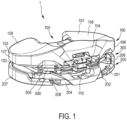
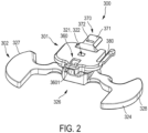
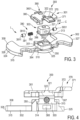
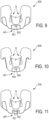
- the tibial trial insert system 1 comprises a bearing component 100, a plate component 200, a spacing adjustment assembly 300 (shown in detail in figs. 2 , 3, 4 ) and a plurality of shims 500, 600, 700 (shown in detail in figs. 9, 10, 11 ), wherein fig. 1 only shows shims 500, 600 of said plurality of shims 500, 600, 700.
- the bearing component 100 has a superior articulating surface 101, an opposing inferior surface 102 and a peripheral wall 103 extending from the inferior surface 102 to the superior articulating surface 101.
- the bearing component 100 further includes an anterior side 104, a posterior side 105, a lateral side 106 and a medial side 107.
- the superior articulating surface 101 is configured to articulate with natural or prosthetic condyles of a distal femur and includes a lateral articulating surface portion 108 and a medial articulating surface portion 109.
- the plate component 200 has a superior surface 201, an opposing inferior fixation surface 202 and a peripheral wall 203 extending from the inferior fixation surface 202 to the superior surface 201.
- the plate component 200 further includes an anterior side 204, a posterior side (without reference sign), a lateral side 206 and a medial side 207.
- the inferior fixation surface 202 is configured for direct or indirect fixation to a proximal end of a tibia.
- the plate component 200 can also be referred to as tibial plateau component.
- the spacing adjustment assembly 300 is configured to be arrangeable between the bearing component 100 and the plate component 200, in particular between the inferior surface 102 of the bearing component 100 and the superior surface 201 of the plate component 200.
- the spacing adjustment assembly 300 comprises a superior connector element 301, an inferior base element 302 and a coupling arrangement C.
- the superior connector element 301 is configured to removably engage with the bearing component 100.
- the inferior base element 302 is configured to removably engage with the plate component 200.
- the coupling arrangement movably couples the connector element 301 with the base element 302 in proximal/distal direction and to a limited extent. In other words, the connector element 301 and the base element 302 are movably and captively coupled to each other by means of the coupling arrangement C.
- the spacing adjustment assembly 300 is intended for adjusting a relative proximal/distal spacing between the bearing component 100 and the plate component 200.
- the spacing adjustment assembly 300 is intended to position the superior articulating surface 101 and/or the bearing component 100 in different height levels relative to the plate component 200, in particular relative to the inferior fixation surface 202.
- Such a spacing or height adjustment is required for trial reposition in knee joint replacement surgery.
- Said trial reposition is an operation step preceding the actual knee joint replacement, wherein sizes, dimensions and/or shapes of the tibial and femoral implant components required for the replacement of the knee joint are determined.
- This application related background of the tibial trial insert system 1 is well-known to those skilled in the art.
- each shim 500, 600, 700 of said plurality of shims is configured to be slidable between the connector element 301 and the base element 302, in particular between an inferior surface 307 of the connector element 301 and a superior surface 308 of the base element 302.
- a single shim or a plurality of stacked shims can be inserted between the connector element 301 and the base element 302.
- a single shim or more than a single shim of the plurality of shims can be used in combination to provide for an additional spacing between the bearing component 100 and the plate component 200.
- the surgeon arranges the spacing adjustment assembly 300 between the bearing component 100 and the plate component 200 and engages the connector element 301 with the bearing component and the base element 302 with the plate component, respectively, in a manner described below in more detail.
- the actual spacing adjustment is achieved by inserting at least one of the shims 500, 600, 700 between the connector element 301 and the base element 302.
- the bearing component 100 For removable engagement with the connector element 301, the bearing component 100 comprises an engagement portion 110 (see in particular figs. 13 , 17 ).
- the engagement portion 110 is countersunk into the inferior surface 102 of the bearing component 100 in the proximal direction.
- the engagement portion 110 and the connector element are configured to form a plug-in connection.
- the connector element 301 and the engagement portion 110 can be plugged together in anterior/posterior direction. In the engaged state, relative movement between the connector element 301 and the bearing component 100 is inhibited at least in proximal/distal direction and in medial/lateral direction.
- the connector element 301 For improved engagement between the connector element 301 and the engagement portion 110, the connector element 301 comprises a spring portion 380.
- the spring portion 380 serves as a fixture/stop for the bearing component 100 and prevents the bearing component 100 from unintended disengagement from the connector element 301.
- the spring portion 380 is configured to generate an audible effect upon reaching a fully engaged state with the engagement portion 110. Said audible effect indicates a correct position engagement of the bearing component on the spacing adjustment assembly 300.
- the base element 302 has a peripheral wall 324 extending between an inferior surface 315 and the superior surface 308. Moreover, the base element 302 has an anterior side 325, a posterior side 326, a lateral side 327 and a medial side 328.
- the peripheral wall 324 defines an outer contour (without reference sign).
- the plate component 200 has a receiving recess 208 (see in particular fig. 1 , 7 ) defining an inner contour (without reference sign) which is at least in portions complementary to the outer contour of the base element 302. In an engaged state, i.e. when the base element 302 is received in the receiving recess 208, the base element 302 is restrained in anterior/posterior direction and lateral/medial direction.
- the coupling arrangement C forms a telescopic mechanism which is extendable in proximal direction and retractable in distal direction.
- the telescopic mechanism is configured to movably and captively couple the connector element 301 with the base element 302.
- the telescopic mechanism comprises a cylinder element 303 which is fixedly connected to the connector element 301 and slidably received in a receiving bore 310 of the base element 302.
- the cylinder element 303 and the receiving bore 310 form a single-stage telescopic cylinder of the telescopic mechanism.
- the cylinder element 303 and the receiving bore 310 extend coaxially in the proximal/distal direction.
- the cylinder element 303 has a distal radial collar 313.
- the bore 310 of the base element 302 has a proximal radial collar 314.
- the distal radial collar 313 of the cylinder element 303 and the proximal radial collar 314 of the base element 302 form an end-stop for limiting the proximal movability of the cylinder element 303 within the bore 310.
- the cylinder element 303 and the bore 310 each comprise a non-circular cross-section.
- the cross-section of the cylinder element and the cross-section of the receiving bore 310 are each rectangular.
- the non-circular cross-sections prevent a relative rotation between the cylinder element 303 and the bore 310 and thus between the connector element 301 and the base element 302.
- the cylinder element 303 is fixedly connected to the connector element 301.
- the connector element 301 comprises a pin hole 322.
- the cylinder element 303 comprises a pin portion 321.
- the pin portion 321 protrudes from a proximal end of the cylinder element 303 in proximal direction and is fixedly inserted into the pin hole 322.
- the pin portion 321 and the pin hole 322 can form an press fit and/or can be bonded together by means of a bonding connection.
- the telescopic mechanism C comprises a latching device L configured for releasably latching the cylinder element 303 in a fully retracted position relative to the base element 302. Releasably latching the telescopic mechanism C in the fully retracted position, i.e. with minimal proximal/distal height, stabilizes and compacts the spacing adjustment assembly 300 which allows for an easy and safe insertion between the bearing component 100 and the plate component 200 during surgery.
- the latching device L comprises at least one resilient latching member 390 connected to the cylinder element 303 and at least one latching portion 394 formed on the base element 302.
- the resilient latching member 390 and the latching portion 394 are configured for a latching interaction to releasably lock the cylinder element 303 to the base element 302.
- the latching connection between the resilient latching member 390 and the latching portion 394 is releasable by pulling the connector element 301 in proximal direction.
- the cylinder element 303 comprises at least one receiving bore 396 and the resilient latching member 390 comprises at least one head portion 391 and at least one compression spring member 392.
- the head portion 391 and the compression spring member 392 are both received in said receiving bore 396.
- the receiving bore 396 extends in medial/lateral direction.
- the head portion 391 extends between a first end 3911 and a second end 3912, wherein the first end 3911 is configured to latch with the latching portion 394, and wherein the compression spring member 392 acts on the second end 3912.
- the compression spring member 392 is configured to bias the head portion 391 into a latching position in which the first end 3911 protrudes from the receiving bore 396 to latch with the latching portion 394.
- the resilient latching member 390 comprises said (first) head portion 391 and a second head portion 393 opposite in medial/lateral direction.
- the base element 302 comprises said (first) latching portion 394 and a second latching portion 395 opposite in medial/lateral direction.
- the compression spring member 392 is located between the first head portion 391 and the second head portion 393 and acts on their respective second ends 3912, 3932.
- the second head portion 393 is received in the receiving bore 396.
- the compression spring member 396 biases the first head portion 391 into the described latching position in which the first end 3911 of the first head portion 391 protrudes from the receiving bore to latch with the first latching portion 394.
- the compression spring member 392 also biases the second head portion 393 into a latching position in which a first end 3931 of the second head portion 393 protrudes from the receiving bore 396 to latch with the second latching portion 395.
- the tibial trial insert system 1 further comprises a handling instrument 800 as shown in figs. 5 to 8 .
- the handling instrument 800 comprises an elongated shaft 820 and a coupling mechanism 840.
- the elongated shaft 820 extends between a proximal end 821 and a distal end 822.
- the coupling mechanism 840 is disposed at the distal end 822 and configured to releasably couple to an anterior coupling portion 370 (see figs. 3, 4 ) of the spacing adjustment assembly 300.
- the handling instrument 800 When releasably coupled to the anterior coupling portion 370, the handling instrument 800 allows for a simple and ergonomic engagement of the spacing adjustment assembly 300 with the bearing component 100 (see fig. 6 ). After engaging the spacing adjustment assembly 300 with the bearing component 100 the handling instrument, with the coupling mechanism 840 still coupled to the anterior coupling portion 370, can be used to insert the assembly 100, 300 into the patient's knee and to engage the base element 302 of the spacing adjustment assembly 300 with the plate component 200 (see fig. 7 ).
- the coupling mechanism 840 comprises a housing 845, a coupling finger 841, a coupling protrusion 846, a spring element 842 arranged inside the housing 845 and therefore not visible in the drawings, and a release button 847.
- the release button 847 is biased by means of the spring element 842 and configured for manual operation, i.e. the release button 847 can be pressed against the bias of the spring element 842 by using a thumb.
- a distal end of the release button 847 forms the coupling finger 841.
- the coupling finger 841 is movable in proximal/distal direction by means of a movement of the release button 847.
- the coupling protrusion 846 protrudes distally from a distal end of the housing 845.
- the anterior coupling portion 370 of the spacing adjustment assembly 300 is formed on the connector element 301.
- the connector element 301 is made of a metal material.
- the connection between the coupling mechanism 840 and the anterior coupling portion has therefore an improved strength and stability in comparison to a coupling of the coupling mechanism to a coupling portion made of plastic material, e.g. the plastic made coupling portion formed on the bearing component.
- the anterior coupling portion 370 comprises a coupling protrusion 371 and a coupling opening 372.
- the coupling protrusion 371 is configured for positive engagement with the coupling protrusion 846 of the coupling mechanism 840.
- the coupling opening 372 is configured for positive engagement with the coupling finger 841 of the coupling mechanism 840.
- the coupling mechanism 840 is also configured for releasable coupling to an anterior coupling portion AP, AP' of each of the plurality of shims 500, 600, 700 (see figs. 9, 10, 11 ).
- the shims 500, 600, 700 depicted in figs. 9, 10, 11 can be denoted as first shim 500, second shim 600 and third shim 700.
- the anterior coupling portion AP' of the third shim 700 is basically identical to the anterior coupling portion 370 of the connector element 301 and has a coupling protrusion 701 and a coupling opening 702.
- the coupling protrusions AP of the first shim 500 and the second shim 600 each have a coupling recess 501, 601 and a coupling opening 502, 602.
- the coupling recesses 501, 601 and the coupling openings 502, 602 are each identical in form and function.
- the coupling recesses 501, 601 are configured to receive the coupling protrusion 846 of the coupling mechanism 840.
- the coupling openings 502, 602 are configured to receive the coupling finger 841.
- each shim of the plurality of shims 500, 600, 700 comprises two spring elements S.
- Each spring element S comprises a latching protrusion P or latching interaction with a complementary latching portion 351 of the base element 302 (see fig. 3 ).
- the complementary latching portion 351 is disposed on or in an outer wall of a boss section 350 of the base element.
- Said boss section 350 comprises the receiving bore 310.
- only one complementary latching portion 351 is visible.
- the boss section 350 comprises two complementary latching portions 351 opposite in medial/lateral direction.
- the spring elements S with their coupling protrusions P prevent an unintended removal of the respective shim 500, 600, 700.
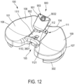
- the tibial trial insert system 1 further comprises a securing component 900 (see figs. 12 to 19 ).
- the securing component 900 is configured for securing the removable engagement between the bearing component 100 and the connector element 301 of the spacing adjustment assembly 300.
- the securing component 900 is configured to be supported on and/or in a support portion 111 of the bearing component 100 and configured for detachable attachment to an attachment portion 360 of the connector element 301.
- the support portion 111 of the bearing component 100 comprises a recessed support surface 1111 and a support opening 1112.
- the recessed support surface 1111 is sunk distally into the articulating surface 101.
- the support opening 1112 is located on the recessed support surface 1111 and extends between the support surface 1111 and the inferior surface 102 of the bearing component 100.
- the recessed support surface 1111 is located between the medial articulating surface portion 109 and the lateral articulating surface portion 108.
- the attachment portion 360 of the connector element 301 comprises an attachment opening 3601.
- the attachment opening 3601 is positioned distally underneath and in line with the support opening 1112.
- the securing component 900 comprises a plug body 901 and a hook member 902.
- the plug body 901 is configured to be plugged on the recessed support surface 1111.
- an outer contour (without reference sign) of the plug body 901 is complementary to an inner contour (without reference sign) of the recessed support surface 1111.
- the hook member 902 is configured to reach through the support opening 1112 and to positively engage with the attachment opening 3601 (see in particular figs. 13 , 18 ).
- the securing component 900 further comprises a locking device 903 for releasably locking to a locking portion 112 of the bearing component 100. Releasably locking the securing component 900 to the bearing component 100 allows to easily attach and detach the securing component from the remaining components of the tibial trial insert system 1.
- the locking portion 112 of the bearing component 100 comprises a locking slit 1121 and the locking device 903 comprises a flat locking member 9031.
- the locking slit 1121 extends in a transversal plane, i.e. in medial/lateral and in anterior/posterior direction and is located at an anterior end of the recessed support surface 1111.
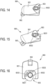
- the flat locking member 9031 is configured to be rotatable relative to the plug body 901 and the hook member 902 between a locking position and a release position.
- the flat locking member is rotatable in said transversal plane of the locking slit 1121 between a locking position (see figs. 13 , 15 , 16 , 18 ) and a release position (see fig. 14 ).
- the flat locking member 9031 positively engages the locking slit 1121.
- the flat locking member 9031 does not positively engage the locking slit 1121.
- the flat locking member 9031 has a non-circular outer contour with two spring portions 9033. Said spring portions 9033 interact with an inner contour of a receiving recess (without reference sign) of the plug body 901 in which the flat locking member 9031 is received.
- the flat locking member 9031 is operatively connected with a screw member 9032. Turning the screw member 9032 rotates the flat locking member 9031 between the locking position and the release position.
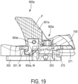
- Fig. 19 illustrates the use of an alternative securing component 900a which can be considered as a variant of the securing component 900.
- the securing component 900a has a differently shaped plug body 901a.
- the plug body 901a forms a stem which is configured to interact with an intercondylar notch of a femoral component.
- the securing component 901a and the securing component 900 can be exchanged against one another. Choosing between the securing component 900 or the alternative securing component 900a allows the surgeon to change from one type of surgical procedure to another.
- the plug body 901 and the hook member 902 form a unitary one-piece design.
- the plug body 901a and the hook member 902a of the securing component 900a are formed as separate parts.
- the plug body 901a is made of a plastic material.
- the hook member 902a is made of a metal material M.
- the hook member 902a is connected to the plug body 901a by means of a pin member 904a.
- the locking device 903a of the securing component 900a is identical with the locking device 903 of the securing component 900.
Landscapes
- Health & Medical Sciences (AREA)
- Orthopedic Medicine & Surgery (AREA)
- Transplantation (AREA)
- Heart & Thoracic Surgery (AREA)
- Oral & Maxillofacial Surgery (AREA)
- Cardiology (AREA)
- Engineering & Computer Science (AREA)
- Biomedical Technology (AREA)
- Physical Education & Sports Medicine (AREA)
- Vascular Medicine (AREA)
- Life Sciences & Earth Sciences (AREA)
- Animal Behavior & Ethology (AREA)
- General Health & Medical Sciences (AREA)
- Public Health (AREA)
- Veterinary Medicine (AREA)
- Prostheses (AREA)
Abstract
A tibial trial insert system (1) comprising:
a bearing component (100) having a superior articulating surface (101) and an inferior surface (102);
a plate component (200) having a superior surface (201) and an inferior surface (202);
a spacing adjustment assembly (300) configured to be arrangeable between the bearing component (100) and the plate component (200), the spacing adjustment assembly (300) having at least one superior connector element (301) configured to removably engage with the bearing component (100), at least one inferior base element (302) configured to removably engage with the plate component (200), and having a coupling arrangement (C) movably coupling the connector element (301) and the base element (302) in proximal/distal direction and to a limited extent; and
a plurality of shims (500, 600, 700), each shim (500, 600, 700) configured to be slidable between the connector element (301) and the base element (302) to adjust a proximal/distal height of the spacing adjustment assembly (300), in order to thereby adjust a relative proximal/distal spacing between the bearing component (100) and the plate component (200).
Description
- The present invention relates to a tibial trial insert system.
- During a total knee arthroplasty, tibial trial insert systems are typically used to assist a surgeon in determining a size, shape or other configuration of a permanent prosthesis for replacing a portion of the natural knee joint. In particular, such tibial trial insert systems are used to determine a relative spacing between a femoral component and a tibial component of the permanent prosthesis.
-
US 2015/0359642 A1 discloses a tibial trial insert system comprising a bearing component having a superior articulating surface and an inferior surface; a base component having a superior surface and an inferior surface, the base component configured to removably engage with the bearing component; and a plurality of shims, each shim configured to be slidable between the inferior surface of the bearing component and the superior surface of the base component to change a relative proximal/distal spacing between the bearing component and the base component. - It is an object of the present invention to provide an alternative tibial trial insert system.
- According to the invention, the tibial trial insert system comprises: a bearing component having a superior articulating surface and an inferior surface; a plate component having a superior surface and an inferior fixation surface; a spacing adjustment assembly configured to be arrangeable between the bearing component and the plate component, the spacing adjustment assembly having at least one superior connector element configured to removably engage with the bearing component, at least one inferior base element configured to removably engage with the plate component, and having a coupling arrangement movably coupling the connector element with the base element in proximal/distal direction and to a limited extent; a plurality of shims, each shim configured to be slidable between the connector element and the base element to adjust a proximal/distal height of the spacing adjustment assembly, in order to thereby adjust a relative proximal/distal spacing between the bearing component and the plate component. The invention avoids, in particular, incorrect adjustment of the proximal/distal spacing between the bearing component and the plate component. To this end, the spacing adjustment assembly only allows a limited proximal/distal relative movement between the bearing component and the plate component. For achieving said limited movement, the connector element and the base element are movably and captively coupled by means of the coupling arrangement. Said limited movement prevents an insertion of an excessive number of shims and thus the setting of too large a proximal/distal height. As a result, the invention helps to prevent errors during surgery and improves patient safety. Moreover, due to the movable yet captive coupling between the connector element and the base element, the spacing adjustment assembly can be handled easily during surgery, in particular in comparison to a mere arrangement of loose and/or non-pre-assembled parts. Preferably, the spacing adjustment assembly is configured to be arrangeable between the inferior surface of the bearing component and the superior surface of the plate component. Preferably, each shim is configured to be slidable between an inferior surface of the connector element and a superior surface of the base element. Preferably, the connector element and the base element are fixed relative to each other by means of the coupling arrangement in anterior/posterior and/or medial/lateral direction. Engagement of the connector element with the bearing component and engagement of the base element with the plate component restrains an anterior/posterior movement and/or a medial/lateral movement between the bearing component and the plate component. For engagement with the base element, the plate component preferably comprises a recess configured for accommodating at least a portion of the base element and for restraining the base element in anterior/posterior direction and/or medial/lateral direction relative to the plate component. For engagement with the connector element, the bearing component preferably comprises an engagement portion which interacts with a complementary engagement portion of the connector element, thereby forming a plug-in, latching and/or snap-in connection. Preferably, the movability between the connector element and the base element in proximal/distal direction is limited by means of an end stop or the like. In this document, the terms "superior", "inferior", "anterior", "posterior", "medial", "lateral", "proximal" and "distal" are used according to their standard anatomical definitions. In this document, the phrase "proximal/distal spacing" denotes a spacing extending in a proximal and/or distal direction. Analogously, the phrase "anterior/posterior" means anterior and/or posterior; the phrase "medial/lateral" means medial and/or lateral. The plate component can also be termed "tibial plateau component".
- In one embodiment, the coupling arrangement forms a telescopic mechanism which is extendable in proximal direction and retractable in distal direction. Providing the coupling arrangement in the form of a telescopic mechanism allows for a simple and robust design. The telescopic mechanism is telescoping in proximal/distal direction and, in this respect, extendable in proximal direction and retractable in distal direction. The telescopic mechanism is fixed to the base element on one end and fixed to the connector element on the other end. The telescopic mechanism is extendable in proximal direction by means of sliding at least one shim of the plurality of shims between the connector element and the base element. Starting from an extended position, the telescopic mechanism is retractable in distal direction by means of removing at least one shim of the plurality of shims between the connector element and the base element. Preferably, the telescopic mechanism comprises at least one cylinder element which is fixedly connected to the connector element and slidably received in a receiving bore of the base element. Hence, the telescopic mechanism has a single stage. Other embodiments can comprise two, three, four, five, six or even more cylinder elements, forming a telescopic cylinder with an according number of stages. Preferably, the proximal/distal movability of the cylinder element within the receiving bore of the base element is limited by means of a proximal end stop and/or a distal end stop. Preferably, the cylinder element and the receiving bore each have a non-circular, preferably oval or rectangular, cross-section, thereby preventing a relative rotation between the connector element and the base element about a proximal/distal axis. The non-circular cross-sections restrain a relative rotation between the connector element and the base element and, thus, between the bearing component and the plate component. Preferably, the telescopic mechanism is extendable between 0 mm and 16 mm, inclusive.
- In one embodiment, the telescopic mechanism comprises a latching device configured for releasably latching the cylinder element in a fully retracted position relative to the base element. Releasably latching the cylinder element to the base element by means of the latching device in said fully retracted position leads to an improved stability and a more compact design when inserting the tibial trial insert system into the patient's knee. The latching can be released by extending the telescopic mechanism in proximal direction, i.e. by pushing or pulling the bearing component in proximal direction, e.g. by sliding at least one shim of the plurality of shims between the connector element and the base element.
- In one embodiment, the latching device comprises at least one resilient matching member connected to the cylinder element and at least one latching portion formed on the base element and configured for latching interaction with the resilient latching member to releasably latch the cylinder element to the base element. Providing the latching device with at least one resilient latching member and at least one latching portion allows for a simple and robust design. The at least one resilient latching member and the at least one latching portion form said releasable latching connection in the fully retracted position of the cylinder element/telescopic mechanism.
- In one embodiment, the cylinder element comprises at least one receiving bore, wherein the resilient latching member comprises at least one head portion extending between a first end and a second end, and at least one compression spring member, the head portion and the compression spring member both being received in said receiving bore of the cylinder element, wherein the first end of the head portion is configured to latch with the latching portion of the base element, and wherein the compression spring member acts on the second end of the head portion to bias the head portion into a latching position in which the first end of the head portion protrudes from the receiving bore of the cylinder element to latch with the latching portion of the base element. The inventors have found that providing the resilient latching member with at least one head portion and at least one compression spring member leads to a simple and robust design that is well suited for invasive applications. Preferably, the at least one receiving bore extends in medial/lateral direction. Alternatively, the at least one receiving bore extends in anterior/posterior direction. The head portion extends coaxially with the receiving bore and is biased by means of the at least one compression spring member. Said bias acts into the latching position. In one embodiment, a first end of the at least one compression spring member acts on the second end of the head portion and a second end of the compression spring member is supported on a portion of the cylinder element. In an alternative embodiment, the resilient latching member comprises two head portions, wherein the compression spring member is arranged axially between said two head portions for acting on their respective second end.
- In one embodiment, the resilient latching member comprises a first head portion and a second head portion opposite in medial/lateral direction, wherein the base element comprises a first latching portion and a second latching portion opposite in medial/lateral direction, wherein the compression spring member is located between said first head portion and second head portion and acts on their respective second end, thereby biasing the first head portion into a latching position in which a first end of the first head portion protrudes from the receiving bore to latch with the first latching portion, and thereby biasing the second head portion into a latching position in which a first end of the second head portion protrudes from the receiving bore to latch with the second latching portion. Both the first head portion and the second head portion are received in the receiving bore of the cylinder element. The compressing spring member is located between the first head portion and the second head portion and biases the first head portion and the second portion into opposite directions. Providing the resilient latching member with two opposite head portions and the base element with two opposite latching portions allows for an improved latching connection. Said improved latching connection has two connection "points", i.e. firstly between the first head portion and the first latching portion and secondly between the second head portion and the second latching portion.
- In one embodiment, the tibial trial insert system further comprises a handling instrument having an elongate shaft and a coupling mechanism arranged distally on said elongate shaft, wherein the coupling mechanism is configured for releasable coupling to an anterior coupling portion of the spacing adjustment assembly. The handling instrument allows for a simplified and ergonomic handling of the spacing adjustment assembly. The handling instrument can be used to arrange the spacing adjustment assembly between the bearing component and the plate component. The elongate shaft extends between a distal end and a proximal end. The coupling mechanism is arranged on the distal end of the elongate shaft. The coupling mechanism is configured for manual operation. For this purpose, an operating element is preferably provided and configured for manually shifting the coupling mechanism between a coupling state and a release state. Said operating element is preferably a button, a switch, a slider or the like. In a preferred embodiment, the anterior coupling portion of the spacing adjustment assembly is formed on the connector element. In an alternative embodiment, the anterior coupling portion is formed on the base element. In yet another embodiment, the anterior coupling portion is formed on the coupling arrangement.
- In one embodiment, the anterior coupling portion is formed on the connector element of the spacing adjustment assembly, wherein the connector element is made of a metal material. Providing the anterior coupling portion on the connector element and making the latter of a metal material allows for an improved strength of the coupling between the coupling mechanism and the coupling portion. It is also possible to provide the anterior coupling portion on the bearing component. However, the bearing component is preferably made of a plastic material and a possible coupling between the coupling mechanism and a coupling portion of the bearing component is therefore less stable and robust in comparison to a coupling between the coupling mechanism and the coupling portion of the metal made connector element. Preferably, the anterior coupling portion forms a protrusion protruding in anterior direction.
- In one embodiment, the coupling mechanism is configured for releasable coupling to an anterior coupling portion of each of the plurality of shims. Configuring the coupling mechanism for releasable coupling to each of the plurality of shims allows for a simplified and ergonomic handling of the shims as well. Hence, the handling instrument can be used for arranging the spacing adjustment assembly between the bearing component and the plate component and for sliding the shims between the connector element and the base element.
- In one embodiment, the tibial trial insert system further comprises a securing component configured to be supported on and/or in a support portion of the bearing component and configured for detachable attachment to an attachment portion of the connector element of the spacing adjustment assembly, thereby releasably securing the removable engagement between the bearing component and the connector element. Providing the tibial trial insert system with said securing component allows for an improved connection between the bearing component and the spacing adjustment assembly. For this purpose, the securing component can be supported on and/or in said support portion of the bearing component and can be attached to said attachment portion of the connector element. The detachable attachment between the securing component and the attachment portion can be, e.g., in the form of a plug-in, latching and/or snap-in connection. The securing component secures the engagement between the bearing component and the connector element at least in proximal/distal direction.
- In one embodiment, the attachment portion and/or the connector element is made of metal material. Making the attachment portion and/or the connector element of a metal material provides for an improved strength and durability of the detachable attachment of the securing component to the attachment portion/connector element. The attachment portion of the connector element can have any form, shape or size suitable for the present purpose.
- In one embodiment, the support portion of the bearing component comprises a recessed support surface which is sunk distally into the articulating surface and a support opening extending between the support surface and an inferior surface of the bearing component, wherein the attachment portion of the connector element comprises an attachment opening positioned distally underneath and in line with the support opening, and wherein the securing component comprises a plug body configured to be plugged on the recessed support surface and a hook member configured to reach through the support opening and to positively engage with the attachment opening. The recessed support surface is preferably flat and configured to support the plug body of the securing component. The support opening is extending between the support surface and the inferior surface of the bearing component and, hence, a throughopening. The attachment opening is positioned underneath and in line with the support opening and configured to positively engage with the hook member. When the securing component is attached, the hook member reaches through the support opening and positively engages with the attachment opening, thereby securing the engagement between the bearing component and the connector element. The plug body defines a shape and size of the securing component. The hook member serves as attachment means for attaching the securing component to the connector element. The plug body and the hook member are fixedly connected. In one embodiment, the plug body and the hook member form a unitary one-piece component. In another embodiment, the plug body and the hook member are made from different materials and form separate parts of the securing component.
- In one embodiment, the hook member is made of a metal material and/or the plug body is made of a plastic material. Making the hook member of a metal material provides for an improved strength of the connection between the hook member and the attachment portion. Preferably, the plastic material of the plug body is identical to a plastic material of the bearing component. This allows for identical material properties, e.g. frictional properties.
- In one embodiment, the securing component comprises a locking device configured for releasably locking to a locking portion of the bearing component. Providing the securing component with said locking device allows for an improved connection between the securing component and the bearing component.
- In one embodiment, the locking portion of the bearing component comprises a locking slit extending in a transversal plane and the locking device of the securing component comprises a flat locking member configured to be rotatable in said transversal plane relative to the securing component between a locking position in which the flat locking member positively engages the locking slit and a release position in which the flat locking member does not positively engage the locking slit. The locking slit of the bearing component extends in said transversal plane and, hence, in medial/lateral and anterior/posterior direction. The flat locking member is rotatably mounted on the securing component and, in particular, rotatable relative to the plug body and/or hook member. The flat locking member is rotatable between said locking position and said release position. Rotating the flat locking member into the release position releases the locking between the securing component and the bearing component to detach the securing component from the attachment portion of the connector element.
- In the following, preferred exemplary embodiments of the invention will be described in detail with reference to the drawings. Throughout the drawings, the same elements will be denoted with the same reference numerals. The drawings schematically show:
- fig. 1
- in a perspective view, an embodiment of a tibial trial insert system having a bearing component, a plate component, a spacing adjustment assembly and a plurality of shims;
- fig. 2
- a perspective view of the spacing adjustment assembly of the tibial trial insert system according to
fig. 1 ; - fig. 3
- the spacing adjustment assembly of
fig. 2 in a perspective exploded view; - fig. 4
- the spacing adjustment assembly of
figs. 2 and3 in longitudinal sectional view with medial/lateral viewing direction; - fig. 5
- a perspective view of a handling instrument configured to handle the components of the tibial trial insert system according to
fig. 1 ; - fig. 6
- a perspective view of a first handling situation in which the handling instrument of
fig. 5 is used to handle the spacing adjustment assembly for engagement with the bearing component; - fig. 7
- in a perspective view, a further handling situation in which the handling instrument is used to handle the bearing component together with the spacing adjustment assembly for engagement with the base component;
- fig. 8
- in a perspective view, a further handling situation in which the handling instrument is used to slide one of the plurality of shims between the bearing component and the plate component to increase a proximal/distal spacing between said components;
- fig. 9, 10, 11
- in top views, different shims of the plurality of shims;
- fig. 12
- in a further perspective view, the tibial trial insert system of
fig. 1 together with a securing component, wherein the securing component is detached from the bearing component and the spacing adjustment assembly; - fig. 13
- in a bottom view, the bearing component together with the attached securing component;
- fig. 14
- in a detailed perspective view, the securing component, wherein a locking device of the securing component occupies a release position;
- fig. 15
- in a further perspective view, the securing component, wherein the locking device occupies a locking position;
- fig. 16
- the securing component of
figs. 14 and 15 in a bottom view with the locking device occupying the locking position; - fig. 17
- a bottom view of the tibial trial insert system with attached securing component and without the plate component;
- fig. 18
- the tibial trial insert system with attached securing component in a longitudinal sectional view and without the plate component, and
- fig. 19
- the tibial trial insert system with a variant of the securing component attached in a further longitudinal sectional view and without the plate component.
- According to
fig. 1 , a tibial trial insert system is provided for use in a knee joint replacement surgery. The tibialtrial insert system 1 comprises abearing component 100, aplate component 200, a spacing adjustment assembly 300 (shown in detail infigs. 2 ,3, 4 ) and a plurality ofshims figs. 9, 10, 11 ), whereinfig. 1 only showsshims shims - The
bearing component 100 has a superior articulatingsurface 101, an opposinginferior surface 102 and aperipheral wall 103 extending from theinferior surface 102 to the superior articulatingsurface 101. Thebearing component 100 further includes ananterior side 104, aposterior side 105, alateral side 106 and amedial side 107. The superior articulatingsurface 101 is configured to articulate with natural or prosthetic condyles of a distal femur and includes a lateral articulatingsurface portion 108 and a medial articulatingsurface portion 109. - The
plate component 200 has asuperior surface 201, an opposinginferior fixation surface 202 and a peripheral wall 203 extending from theinferior fixation surface 202 to thesuperior surface 201. Theplate component 200 further includes ananterior side 204, a posterior side (without reference sign), alateral side 206 and amedial side 207. Theinferior fixation surface 202 is configured for direct or indirect fixation to a proximal end of a tibia. Theplate component 200 can also be referred to as tibial plateau component. - The
spacing adjustment assembly 300 is configured to be arrangeable between the bearingcomponent 100 and theplate component 200, in particular between theinferior surface 102 of thebearing component 100 and thesuperior surface 201 of theplate component 200. Thespacing adjustment assembly 300 comprises asuperior connector element 301, aninferior base element 302 and a coupling arrangement C. - The
superior connector element 301 is configured to removably engage with thebearing component 100. Theinferior base element 302 is configured to removably engage with theplate component 200. The coupling arrangement movably couples theconnector element 301 with thebase element 302 in proximal/distal direction and to a limited extent. In other words, theconnector element 301 and thebase element 302 are movably and captively coupled to each other by means of the coupling arrangement C. - The
spacing adjustment assembly 300 is intended for adjusting a relative proximal/distal spacing between the bearingcomponent 100 and theplate component 200. In other words, thespacing adjustment assembly 300 is intended to position the superior articulatingsurface 101 and/or thebearing component 100 in different height levels relative to theplate component 200, in particular relative to theinferior fixation surface 202. Such a spacing or height adjustment is required for trial reposition in knee joint replacement surgery. Said trial reposition is an operation step preceding the actual knee joint replacement, wherein sizes, dimensions and/or shapes of the tibial and femoral implant components required for the replacement of the knee joint are determined. This application related background of the tibialtrial insert system 1 is well-known to those skilled in the art. - With respect to said height and/or spacing adjustment, each
shim connector element 301 and thebase element 302, in particular between aninferior surface 307 of theconnector element 301 and asuperior surface 308 of thebase element 302. - For that purpose, a single shim or a plurality of stacked shims can be inserted between the
connector element 301 and thebase element 302. In other words, a single shim or more than a single shim of the plurality of shims can be used in combination to provide for an additional spacing between the bearingcomponent 100 and theplate component 200. - For adjusting the proximal/distal spacing, the surgeon arranges the
spacing adjustment assembly 300 between the bearingcomponent 100 and theplate component 200 and engages theconnector element 301 with the bearing component and thebase element 302 with the plate component, respectively, in a manner described below in more detail. The actual spacing adjustment is achieved by inserting at least one of theshims connector element 301 and thebase element 302. - For removable engagement with the
connector element 301, thebearing component 100 comprises an engagement portion 110 (see in particularfigs. 13 ,17 ). Theengagement portion 110 is countersunk into theinferior surface 102 of thebearing component 100 in the proximal direction. In the illustrated embodiment, theengagement portion 110 and the connector element are configured to form a plug-in connection. Theconnector element 301 and theengagement portion 110 can be plugged together in anterior/posterior direction. In the engaged state, relative movement between theconnector element 301 and thebearing component 100 is inhibited at least in proximal/distal direction and in medial/lateral direction. - For improved engagement between the
connector element 301 and theengagement portion 110, theconnector element 301 comprises aspring portion 380. Thespring portion 380 serves as a fixture/stop for thebearing component 100 and prevents thebearing component 100 from unintended disengagement from theconnector element 301. Thespring portion 380 is configured to generate an audible effect upon reaching a fully engaged state with theengagement portion 110. Said audible effect indicates a correct position engagement of the bearing component on thespacing adjustment assembly 300. - The
base element 302 has aperipheral wall 324 extending between aninferior surface 315 and thesuperior surface 308. Moreover, thebase element 302 has ananterior side 325, aposterior side 326, alateral side 327 and amedial side 328. Theperipheral wall 324 defines an outer contour (without reference sign). For removable engagement with thebase element 302, theplate component 200 has a receiving recess 208 (see in particularfig. 1 ,7 ) defining an inner contour (without reference sign) which is at least in portions complementary to the outer contour of thebase element 302. In an engaged state, i.e. when thebase element 302 is received in the receivingrecess 208, thebase element 302 is restrained in anterior/posterior direction and lateral/medial direction. - The coupling arrangement C forms a telescopic mechanism which is extendable in proximal direction and retractable in distal direction. The telescopic mechanism is configured to movably and captively couple the
connector element 301 with thebase element 302. - The telescopic mechanism comprises a
cylinder element 303 which is fixedly connected to theconnector element 301 and slidably received in a receivingbore 310 of thebase element 302. Thecylinder element 303 and the receiving bore 310 form a single-stage telescopic cylinder of the telescopic mechanism. - The
cylinder element 303 and the receiving bore 310 extend coaxially in the proximal/distal direction. - The
cylinder element 303 has a distalradial collar 313. Thebore 310 of thebase element 302 has a proximalradial collar 314. The distalradial collar 313 of thecylinder element 303 and the proximalradial collar 314 of thebase element 302 form an end-stop for limiting the proximal movability of thecylinder element 303 within thebore 310. - The
cylinder element 303 and thebore 310 each comprise a non-circular cross-section. In the illustrated embodiment, the cross-section of the cylinder element and the cross-section of the receiving bore 310 are each rectangular. The non-circular cross-sections prevent a relative rotation between thecylinder element 303 and thebore 310 and thus between theconnector element 301 and thebase element 302. - The
cylinder element 303 is fixedly connected to theconnector element 301. Theconnector element 301 comprises apin hole 322. Thecylinder element 303 comprises apin portion 321. Thepin portion 321 protrudes from a proximal end of thecylinder element 303 in proximal direction and is fixedly inserted into thepin hole 322. Thepin portion 321 and thepin hole 322 can form an press fit and/or can be bonded together by means of a bonding connection. - The telescopic mechanism C comprises a latching device L configured for releasably latching the
cylinder element 303 in a fully retracted position relative to thebase element 302. Releasably latching the telescopic mechanism C in the fully retracted position, i.e. with minimal proximal/distal height, stabilizes and compacts thespacing adjustment assembly 300 which allows for an easy and safe insertion between the bearingcomponent 100 and theplate component 200 during surgery. - In the illustrated embodiment, the latching device L comprises at least one
resilient latching member 390 connected to thecylinder element 303 and at least one latchingportion 394 formed on thebase element 302. Theresilient latching member 390 and the latchingportion 394 are configured for a latching interaction to releasably lock thecylinder element 303 to thebase element 302. - The latching connection between the resilient latching
member 390 and the latchingportion 394 is releasable by pulling theconnector element 301 in proximal direction. - In the illustrated embodiment, the
cylinder element 303 comprises at least one receivingbore 396 and the resilient latchingmember 390 comprises at least onehead portion 391 and at least onecompression spring member 392. Thehead portion 391 and thecompression spring member 392 are both received in said receivingbore 396. In the illustrated embodiment, the receivingbore 396 extends in medial/lateral direction. - The
head portion 391 extends between afirst end 3911 and asecond end 3912, wherein thefirst end 3911 is configured to latch with the latchingportion 394, and wherein thecompression spring member 392 acts on thesecond end 3912. Thecompression spring member 392 is configured to bias thehead portion 391 into a latching position in which thefirst end 3911 protrudes from the receiving bore 396 to latch with the latchingportion 394. - In the illustrated embodiment, the resilient latching
member 390 comprises said (first)head portion 391 and asecond head portion 393 opposite in medial/lateral direction. Moreover, thebase element 302 comprises said (first) latchingportion 394 and asecond latching portion 395 opposite in medial/lateral direction. Thecompression spring member 392 is located between thefirst head portion 391 and thesecond head portion 393 and acts on their respective second ends 3912, 3932. Thesecond head portion 393 is received in the receivingbore 396. Thecompression spring member 396 biases thefirst head portion 391 into the described latching position in which thefirst end 3911 of thefirst head portion 391 protrudes from the receiving bore to latch with thefirst latching portion 394. Thecompression spring member 392 also biases thesecond head portion 393 into a latching position in which afirst end 3931 of thesecond head portion 393 protrudes from the receiving bore 396 to latch with thesecond latching portion 395. - In the illustrated embodiment, the tibial
trial insert system 1 further comprises ahandling instrument 800 as shown infigs. 5 to 8 . Thehandling instrument 800 comprises anelongated shaft 820 and acoupling mechanism 840. - The
elongated shaft 820 extends between aproximal end 821 and adistal end 822. - The
coupling mechanism 840 is disposed at thedistal end 822 and configured to releasably couple to an anterior coupling portion 370 (seefigs. 3, 4 ) of thespacing adjustment assembly 300. - When releasably coupled to the
anterior coupling portion 370, thehandling instrument 800 allows for a simple and ergonomic engagement of thespacing adjustment assembly 300 with the bearing component 100 (seefig. 6 ). After engaging thespacing adjustment assembly 300 with thebearing component 100 the handling instrument, with thecoupling mechanism 840 still coupled to theanterior coupling portion 370, can be used to insert theassembly base element 302 of thespacing adjustment assembly 300 with the plate component 200 (seefig. 7 ). - In the illustrated embodiment, the
coupling mechanism 840 comprises ahousing 845, acoupling finger 841, acoupling protrusion 846, aspring element 842 arranged inside thehousing 845 and therefore not visible in the drawings, and arelease button 847. - The
release button 847 is biased by means of thespring element 842 and configured for manual operation, i.e. therelease button 847 can be pressed against the bias of thespring element 842 by using a thumb. A distal end of therelease button 847 forms thecoupling finger 841. Thecoupling finger 841 is movable in proximal/distal direction by means of a movement of therelease button 847. - The
coupling protrusion 846 protrudes distally from a distal end of thehousing 845. - In the illustrated embodiment, the
anterior coupling portion 370 of thespacing adjustment assembly 300 is formed on theconnector element 301. Theconnector element 301 is made of a metal material. The connection between thecoupling mechanism 840 and the anterior coupling portion has therefore an improved strength and stability in comparison to a coupling of the coupling mechanism to a coupling portion made of plastic material, e.g. the plastic made coupling portion formed on the bearing component. - In the illustrated embodiment, the
anterior coupling portion 370 comprises acoupling protrusion 371 and acoupling opening 372. Thecoupling protrusion 371 is configured for positive engagement with thecoupling protrusion 846 of thecoupling mechanism 840. Thecoupling opening 372 is configured for positive engagement with thecoupling finger 841 of thecoupling mechanism 840. - In the illustrated embodiment, the
coupling mechanism 840 is also configured for releasable coupling to an anterior coupling portion AP, AP' of each of the plurality ofshims figs. 9, 10, 11 ). - The
shims figs. 9, 10, 11 can be denoted asfirst shim 500,second shim 600 andthird shim 700. - The anterior coupling portion AP' of the
third shim 700 is basically identical to theanterior coupling portion 370 of theconnector element 301 and has acoupling protrusion 701 and acoupling opening 702. - The coupling protrusions AP of the
first shim 500 and thesecond shim 600 each have acoupling recess coupling opening coupling openings coupling protrusion 846 of thecoupling mechanism 840. Thecoupling openings coupling finger 841. - In the illustrated embodiment, each shim of the plurality of
shims complementary latching portion 351 of the base element 302 (seefig. 3 ). - In the illustrated embodiment, the
complementary latching portion 351 is disposed on or in an outer wall of aboss section 350 of the base element. Saidboss section 350 comprises the receivingbore 310. In the drawings, only onecomplementary latching portion 351 is visible. However, theboss section 350 comprises twocomplementary latching portions 351 opposite in medial/lateral direction. The spring elements S with their coupling protrusions P prevent an unintended removal of therespective shim - In the illustrated embodiment, the tibial
trial insert system 1 further comprises a securing component 900 (seefigs. 12 to 19 ). The securingcomponent 900 is configured for securing the removable engagement between the bearingcomponent 100 and theconnector element 301 of thespacing adjustment assembly 300. For this purpose, the securingcomponent 900 is configured to be supported on and/or in asupport portion 111 of thebearing component 100 and configured for detachable attachment to anattachment portion 360 of theconnector element 301. - In the illustrated embodiment, the
support portion 111 of thebearing component 100 comprises a recessedsupport surface 1111 and asupport opening 1112. The recessedsupport surface 1111 is sunk distally into the articulatingsurface 101. Thesupport opening 1112 is located on the recessedsupport surface 1111 and extends between thesupport surface 1111 and theinferior surface 102 of thebearing component 100. The recessedsupport surface 1111 is located between the medial articulatingsurface portion 109 and the lateral articulatingsurface portion 108. - The
attachment portion 360 of theconnector element 301 comprises anattachment opening 3601. When thespacing adjustment assembly 300 is engaged with thebearing component 100, theattachment opening 3601 is positioned distally underneath and in line with thesupport opening 1112. - In the illustrated embodiment, the securing
component 900 comprises aplug body 901 and ahook member 902. - The
plug body 901 is configured to be plugged on the recessedsupport surface 1111. In the illustrated embodiment, an outer contour (without reference sign) of theplug body 901 is complementary to an inner contour (without reference sign) of the recessedsupport surface 1111. - The
hook member 902 is configured to reach through thesupport opening 1112 and to positively engage with the attachment opening 3601 (see in particularfigs. 13 ,18 ). - In the illustrated embodiment, the securing
component 900 further comprises alocking device 903 for releasably locking to a lockingportion 112 of thebearing component 100. Releasably locking the securingcomponent 900 to thebearing component 100 allows to easily attach and detach the securing component from the remaining components of the tibialtrial insert system 1. - In the illustrated embodiment, the locking
portion 112 of thebearing component 100 comprises alocking slit 1121 and thelocking device 903 comprises aflat locking member 9031. - The locking slit 1121 extends in a transversal plane, i.e. in medial/lateral and in anterior/posterior direction and is located at an anterior end of the recessed
support surface 1111. - The
flat locking member 9031 is configured to be rotatable relative to theplug body 901 and thehook member 902 between a locking position and a release position. When theplug body 901 is supported on the recessedsupport surface 111, the flat locking member is rotatable in said transversal plane of thelocking slit 1121 between a locking position (seefigs. 13 ,15 ,16 ,18 ) and a release position (seefig. 14 ). In the locking position, theflat locking member 9031 positively engages thelocking slit 1121. In the release position, theflat locking member 9031 does not positively engage thelocking slit 1121. - In the illustrated embodiment, the
flat locking member 9031 has a non-circular outer contour with twospring portions 9033. Saidspring portions 9033 interact with an inner contour of a receiving recess (without reference sign) of theplug body 901 in which theflat locking member 9031 is received. Theflat locking member 9031 is operatively connected with ascrew member 9032. Turning thescrew member 9032 rotates theflat locking member 9031 between the locking position and the release position. -
Fig. 19 illustrates the use of analternative securing component 900a which can be considered as a variant of the securingcomponent 900. The securingcomponent 900a has a differently shapedplug body 901a. In particular, theplug body 901a forms a stem which is configured to interact with an intercondylar notch of a femoral component. The securingcomponent 901a and the securingcomponent 900 can be exchanged against one another. Choosing between the securingcomponent 900 or thealternative securing component 900a allows the surgeon to change from one type of surgical procedure to another. - Referring to the
securing component 900, theplug body 901 and thehook member 902 form a unitary one-piece design. In contrast, theplug body 901a and thehook member 902a of thesecuring component 900a are formed as separate parts. Theplug body 901a is made of a plastic material. Thehook member 902a is made of a metal material M. Thehook member 902a is connected to theplug body 901a by means of apin member 904a. Thelocking device 903a of thesecuring component 900a is identical with thelocking device 903 of the securingcomponent 900.
Claims (15)
- A tibial trial insert system (1) comprising:a bearing component (100) having a superior articulating surface (101) and an inferior surface (102);a plate component (200) having a superior surface (201) and an inferior surface (202);a spacing adjustment assembly (300) configured to be arrangeable between the bearing component (100) and the plate component (200), the spacing adjustment assembly (300) having at least one superior connector element (301) configured to removably engage with the bearing component (100), at least one inferior base element (302) configured to removably engage with the plate component (200), and having a coupling arrangement (C) movably coupling the connector element (301) and the base element (302) in proximal/distal direction and to a limited extent; anda plurality of shims (500, 600, 700), each shim (500, 600, 700) configured to be slidable between the connector element (301) and the base element (302) to adjust a proximal/distal height of the spacing adjustment assembly (300), in order to thereby adjust a relative proximal/distal spacing between the bearing component (100) and the plate component (200).
- The tibial trial insert system (1) according to claim 1, wherein the coupling arrangement (C) forms a telescopic mechanism which is extendable in proximal direction and retractable in distal direction and comprises at least one cylinder element (303) which is fixedly connected to the connector element (301) and slidably received in a receiving bore (310) of the base element (302).
- The tibial trial insert system (1) according to claim 2, wherein the telescopic mechanism comprises a latching device (L) configured for releasably latching the cylinder element (303) in a fully retracted position relative to the base element (302).
- The tibial trial insert system (1) according to claim 3, wherein the latching device (L) comprises at least one resilient latching member (390) connected to the cylinder element (303) and at least one latching portion (394) formed on the base element (302) and configured for latching interaction with the resilient latching member (390) to releasably latch the cylinder element (303) to the base element (302).
- The tibial trial insert system (1) according to claim 4, wherein the cylinder element (303) comprises at least one receiving bore (396), wherein the resilient latching member (390) comprises at least one head portion (391) extending between a first end (3911) and a second end (3912), and at least one compression spring member (392), the head portion (391) and the compression spring member (392) both being received in said receiving bore (396), wherein the first end (3911) of the head portion (391) is configured to latch with the latching portion (394) of the base element (392), and wherein the compression spring member (392) acts on the second end (3912) of the head portion (391) to bias the head portion (391) into a latching position in which the first end (3911) of the head portion (391) protrudes from the receiving bore (396) of the cylinder element (303) to latch with the latching portion (394) of the base element (302).
- The tibial trial insert system (1) according to claim 5, wherein the resilient latching member (390) comprises a first head portion (391) and a second head portion (393) opposite in medial/lateral direction, wherein the base element (302) comprises a first latching portion (394) and a second latching (395) portion opposite in medial/lateral direction, wherein the compression spring member (392) is located between said first head portion (391) and second head portion (393) and acts on their second ends (3912, 3932), thereby biasing the first head portion (391) into a latching position in which a first end (3911) of the first head portion (391) protrudes from the receiving bore (396) to latch with the first latching portion (394), and thereby biasing the second head portion (393) into a latching position in which a first end (3931) of the second head portion (393) protrudes from the receiving bore (396) to latch with the second latching portion (395).
- The tibial trial insert system (1) according to any of the preceding claims, further comprising a handling instrument (800) having an elongated shaft (820) and a coupling mechanism (840) arranged distally on said elongated shaft (820), wherein the coupling mechanism (840) is configured for releasable coupling to an anterior coupling portion (370) of the spacing adjustment assembly (300).
- The tibial trial insert system (1) according to claim 7, wherein the anterior coupling portion (370) is formed on the connector element (301) of the spacing adjustment assembly (300), and wherein the connector element (301) is made of a metal material.
- The tibial trial insert system (1) according to claim 7 or 8, wherein the coupling mechanism (840) is configured for releasable coupling to an anterior coupling portion (AP, AP') of each of the plurality of shims (500, 600, 700).
- The tibial trial insert system (1) according to any of the preceding claims, further comprising a securing component (900, 900a) configured to be supported on and/or in a support portion (111) of the bearing component (100) and configured for detachable attachment to an attachment portion (360) of the connector element (301) of the spacing adjustment assembly (300), thereby releasably securing the removable engagement between the bearing component (100) and the connector element (301).
- The tibial trial insert system (1) according to claim 10, wherein the attachment portion (360) and/or the connector element (301) is made of a metal material.
- The tibial trial insert system (1) according to claim 10 or 11, wherein the support portion (111) of the bearing component (100) comprises a recessed support surface (1111) which is sunk distally into the articulating surface (101) and a support opening (1112) extending between the support surface (1111) and an inferior surface (102) of the bearing component (100), wherein the attachment portion (360) of the connector element (301) comprises an attachment opening (3601) positioned distally underneath and in line with the support opening (1112), and wherein the securing component (900, 900a) comprises a plug body (901, 901a) configured to be plugged on the recessed support surface (1111) and a hook member (902, 902a) configured to reach through the support opening (1112) and to positively engage with the attachment opening (3061).
- The tibial trial insert system (1) according to claim 12, wherein the hook member (902a) is made of a metal material and/or the plug body (901, 901a) is made of a plastic material.
- The tibial trial insert system (1) according to any of claims 10 to 13, wherein the securing component (900, 900a) comprises a locking device (903, 903a) configured for releasably locking to a locking portion (112) of the bearing component (100).
- The tibial trial insert system (1) according to claim 14, wherein the locking portion (112) of the bearing component (100) comprises a locking slit (1121) extending in a transversal plane and the locking device (903, 903a) of the securing component (900, 900a) comprises a flat locking member (9031) configured to be rotatable in said transversal plane relative to the securing component (900, 900a) between a locking position in which the flat locking member (9031) positively engages the locking slit (1121) and a release position in which the flat locking member (9031) does not positively engage the locking slit (1121).
Priority Applications (3)
| Application Number | Priority Date | Filing Date | Title |
|---|---|---|---|
| EP23208756.9A EP4552615A1 (en) | 2023-11-09 | 2023-11-09 | Tibial trial insert system |
| JP2024192954A JP2025081248A (en) | 2023-11-09 | 2024-11-01 | Tibia trial insert system |
| US18/939,769 US20250152382A1 (en) | 2023-11-09 | 2024-11-07 | Tibial trial insert system |
Applications Claiming Priority (1)
| Application Number | Priority Date | Filing Date | Title |
|---|---|---|---|
| EP23208756.9A EP4552615A1 (en) | 2023-11-09 | 2023-11-09 | Tibial trial insert system |
Publications (1)
| Publication Number | Publication Date |
|---|---|
| EP4552615A1 true EP4552615A1 (en) | 2025-05-14 |
Family
ID=88778837
Family Applications (1)
| Application Number | Title | Priority Date | Filing Date |
|---|---|---|---|
| EP23208756.9A Pending EP4552615A1 (en) | 2023-11-09 | 2023-11-09 | Tibial trial insert system |
Country Status (3)
| Country | Link |
|---|---|
| US (1) | US20250152382A1 (en) |
| EP (1) | EP4552615A1 (en) |
| JP (1) | JP2025081248A (en) |
Citations (5)
| Publication number | Priority date | Publication date | Assignee | Title |
|---|---|---|---|---|
| US20130261759A1 (en) * | 2012-03-30 | 2013-10-03 | Zimmer, Inc. | Tibial prosthesis systems, kits, and methods |
| US20160324647A1 (en) * | 2010-12-17 | 2016-11-10 | Zimmer, Inc. | Provisional tibial prosthesis system |
| EP4082486A1 (en) * | 2021-04-27 | 2022-11-02 | Aesculap AG | Tibial trial insert system |
| EP4082485A1 (en) * | 2021-04-27 | 2022-11-02 | Aesculap AG | Tibial trial insert system |
| EP4115852A1 (en) * | 2021-07-05 | 2023-01-11 | Aesculap AG | Tibial trial insert system |
-
2023
- 2023-11-09 EP EP23208756.9A patent/EP4552615A1/en active Pending
-
2024
- 2024-11-01 JP JP2024192954A patent/JP2025081248A/en active Pending
- 2024-11-07 US US18/939,769 patent/US20250152382A1/en active Pending
Patent Citations (6)
| Publication number | Priority date | Publication date | Assignee | Title |
|---|---|---|---|---|
| US20160324647A1 (en) * | 2010-12-17 | 2016-11-10 | Zimmer, Inc. | Provisional tibial prosthesis system |
| US20130261759A1 (en) * | 2012-03-30 | 2013-10-03 | Zimmer, Inc. | Tibial prosthesis systems, kits, and methods |
| US20150359642A1 (en) | 2012-03-30 | 2015-12-17 | Zimmer, Inc. | Tibial prosthesis systems, kits, and methods |
| EP4082486A1 (en) * | 2021-04-27 | 2022-11-02 | Aesculap AG | Tibial trial insert system |
| EP4082485A1 (en) * | 2021-04-27 | 2022-11-02 | Aesculap AG | Tibial trial insert system |
| EP4115852A1 (en) * | 2021-07-05 | 2023-01-11 | Aesculap AG | Tibial trial insert system |
Also Published As
| Publication number | Publication date |
|---|---|
| JP2025081248A (en) | 2025-05-27 |
| US20250152382A1 (en) | 2025-05-15 |
Similar Documents
| Publication | Publication Date | Title |
|---|---|---|
| US12097128B2 (en) | System and method for preparing a patient's femur in an orthopaedic joint replacement procedure | |
| US6827739B2 (en) | Easily assembled provisional orthopaedic implant | |
| US5458637A (en) | Orthopaedic base component with modular augmentation block | |
| US5733290A (en) | Quick-release tibial alignment handle | |
| EP4082485B1 (en) | Tibial trial insert system | |
| JP3949765B2 (en) | Artificial knee joint implant tool system and universal tool | |
| JP4034378B2 (en) | Alternative femoral head adapter, alternative femoral head system and alternative femoral head | |
| US20060074432A1 (en) | Modular medical tool and connector | |
| CN103002834B (en) | Prosthetic limb that partially replaces tubular bone | |
| US20150157335A1 (en) | Arthroplasty systems and methods for optimally aligning and tensioning a knee prosthesis | |
| EP4225165B1 (en) | Patella preparation system | |
| AU2011330978B2 (en) | Surgical instrument system, surgical alignment guide and surgical rod | |
| US12053386B2 (en) | Orthopaedic surgical instrument system and a method of trialing an orthopaedic prosthetic assembly | |
| EP4552615A1 (en) | Tibial trial insert system | |
| US20240307193A1 (en) | Implant extractor | |
| DE102022207575A1 (en) | Surgical instrument |
Legal Events
| Date | Code | Title | Description |
|---|---|---|---|
| PUAI | Public reference made under article 153(3) epc to a published international application that has entered the european phase |
Free format text: ORIGINAL CODE: 0009012 |
|
| STAA | Information on the status of an ep patent application or granted ep patent |
Free format text: STATUS: THE APPLICATION HAS BEEN PUBLISHED |
|
| AK | Designated contracting states |
Kind code of ref document: A1 Designated state(s): AL AT BE BG CH CY CZ DE DK EE ES FI FR GB GR HR HU IE IS IT LI LT LU LV MC ME MK MT NL NO PL PT RO RS SE SI SK SM TR |
|
| STAA | Information on the status of an ep patent application or granted ep patent |
Free format text: STATUS: REQUEST FOR EXAMINATION WAS MADE |
|
| 17P | Request for examination filed |
Effective date: 20251103 |