EP4552573A1 - Earpiece-type electrode - Google Patents
Earpiece-type electrode Download PDFInfo
- Publication number
- EP4552573A1 EP4552573A1 EP23835452.6A EP23835452A EP4552573A1 EP 4552573 A1 EP4552573 A1 EP 4552573A1 EP 23835452 A EP23835452 A EP 23835452A EP 4552573 A1 EP4552573 A1 EP 4552573A1
- Authority
- EP
- European Patent Office
- Prior art keywords
- truncated
- axial end
- end portion
- earpiece
- wall portion
- Prior art date
- Legal status (The legal status is an assumption and is not a legal conclusion. Google has not performed a legal analysis and makes no representation as to the accuracy of the status listed.)
- Pending
Links
Images




Classifications
-
- A—HUMAN NECESSITIES
- A61—MEDICAL OR VETERINARY SCIENCE; HYGIENE
- A61B—DIAGNOSIS; SURGERY; IDENTIFICATION
- A61B5/00—Measuring for diagnostic purposes; Identification of persons
- A61B5/24—Detecting, measuring or recording bioelectric or biomagnetic signals of the body or parts thereof
- A61B5/25—Bioelectric electrodes therefor
- A61B5/263—Bioelectric electrodes therefor characterised by the electrode materials
-
- A—HUMAN NECESSITIES
- A61—MEDICAL OR VETERINARY SCIENCE; HYGIENE
- A61B—DIAGNOSIS; SURGERY; IDENTIFICATION
- A61B5/00—Measuring for diagnostic purposes; Identification of persons
- A61B5/24—Detecting, measuring or recording bioelectric or biomagnetic signals of the body or parts thereof
- A61B5/25—Bioelectric electrodes therefor
- A61B5/279—Bioelectric electrodes therefor specially adapted for particular uses
- A61B5/291—Bioelectric electrodes therefor specially adapted for particular uses for electroencephalography [EEG]
-
- A—HUMAN NECESSITIES
- A61—MEDICAL OR VETERINARY SCIENCE; HYGIENE
- A61B—DIAGNOSIS; SURGERY; IDENTIFICATION
- A61B5/00—Measuring for diagnostic purposes; Identification of persons
- A61B5/24—Detecting, measuring or recording bioelectric or biomagnetic signals of the body or parts thereof
- A61B5/316—Modalities, i.e. specific diagnostic methods
- A61B5/369—Electroencephalography [EEG]
- A61B5/377—Electroencephalography [EEG] using evoked responses
- A61B5/38—Acoustic or auditory stimuli
-
- A—HUMAN NECESSITIES
- A61—MEDICAL OR VETERINARY SCIENCE; HYGIENE
- A61B—DIAGNOSIS; SURGERY; IDENTIFICATION
- A61B5/00—Measuring for diagnostic purposes; Identification of persons
- A61B5/68—Arrangements of detecting, measuring or recording means, e.g. sensors, in relation to patient
- A61B5/6801—Arrangements of detecting, measuring or recording means, e.g. sensors, in relation to patient specially adapted to be attached to or worn on the body surface
- A61B5/6813—Specially adapted to be attached to a specific body part
- A61B5/6814—Head
- A61B5/6815—Ear
- A61B5/6817—Ear canal
-
- A—HUMAN NECESSITIES
- A61—MEDICAL OR VETERINARY SCIENCE; HYGIENE
- A61N—ELECTROTHERAPY; MAGNETOTHERAPY; RADIATION THERAPY; ULTRASOUND THERAPY
- A61N1/00—Electrotherapy; Circuits therefor
- A61N1/02—Details
- A61N1/04—Electrodes
- A61N1/0404—Electrodes for external use
- A61N1/0472—Structure-related aspects
-
- A—HUMAN NECESSITIES
- A61—MEDICAL OR VETERINARY SCIENCE; HYGIENE
- A61B—DIAGNOSIS; SURGERY; IDENTIFICATION
- A61B2560/00—Constructional details of operational features of apparatus; Accessories for medical measuring apparatus
- A61B2560/04—Constructional details of apparatus
- A61B2560/0462—Apparatus with built-in sensors
- A61B2560/0468—Built-in electrodes
-
- A—HUMAN NECESSITIES
- A61—MEDICAL OR VETERINARY SCIENCE; HYGIENE
- A61B—DIAGNOSIS; SURGERY; IDENTIFICATION
- A61B5/00—Measuring for diagnostic purposes; Identification of persons
- A61B5/02—Detecting, measuring or recording for evaluating the cardiovascular system, e.g. pulse, heart rate, blood pressure or blood flow
- A61B5/026—Measuring blood flow
-
- H—ELECTRICITY
- H04—ELECTRIC COMMUNICATION TECHNIQUE
- H04R—LOUDSPEAKERS, MICROPHONES, GRAMOPHONE PICK-UPS OR LIKE ACOUSTIC ELECTROMECHANICAL TRANSDUCERS; ELECTRIC HEARING AIDS; PUBLIC ADDRESS SYSTEMS
- H04R1/00—Details of transducers, loudspeakers or microphones
- H04R1/10—Earpieces; Attachments therefor ; Earphones; Monophonic headphones
- H04R1/1016—Earpieces of the intra-aural type
-
- H—ELECTRICITY
- H04—ELECTRIC COMMUNICATION TECHNIQUE
- H04R—LOUDSPEAKERS, MICROPHONES, GRAMOPHONE PICK-UPS OR LIKE ACOUSTIC ELECTROMECHANICAL TRANSDUCERS; ELECTRIC HEARING AIDS; PUBLIC ADDRESS SYSTEMS
- H04R1/00—Details of transducers, loudspeakers or microphones
- H04R1/10—Earpieces; Attachments therefor ; Earphones; Monophonic headphones
- H04R1/1091—Details not provided for in groups H04R1/1008 - H04R1/1083
Definitions
- the present invention relates to an earpiece-type electrode.
- the earpiece-type electrode is inserted into an external auditory canal of a mammal including a human, or a bird.
- Japanese Patent Application Laid-Open Publication No. 2011-217986 discloses an electrode having a substantially cylindrical shape similar to an earpiece of a canal-type earphone. This electrode is inserted into an external auditory canal of a human to be used for supplying electric current to a skull or measuring a brain wave.
- a earpiece of an earphone used for listening to music is formed of a soft material.
- Rubber hardness of the earpiece measured by a type-A durometer specified in JIS K 6253 (2012) is generally equal to or smaller than 30 degrees. Accordingly, the earpiece of the earphone can easily follow a shape and size of an external auditory canal which differ among individuals.
- an earpiece-type electrode includes a large amount of electrically conductive fillers mixed for enhancing an electrical conductivity of the electrode. For this reason, the earpiece-type electrode is formed of the hard material. Rubber hardness of the electrode measured by a type-A durometer is generally in a range from 60 degrees to 70 degrees. Thus, some persons feel discomfort such as oppression or pain in a case of wearing the earpiece-type electrodes for a long time.
- the earpiece-type electrode stably contacts with an inner surface of an external auditory canal over a wide area at a certain degree of contact pressure, in order to secure electrical connection with the living body. Reducing hardness of the earpiece-type electrode causes the earpiece-type electrode to become more likely to buckle at the time of being put into the external auditory canal. Thus, there is a possibility of a decrease in a contact area between the earpiece-type electrode and the inner surface of the external auditory canal and a partial decrease in the contact pressure.
- an earpiece-type electrode having an appropriate size Since a shape and size of an external auditory canal differ among individuals, it is preferable to select an earpiece-type electrode having an appropriate size.
- An earpiece-type electrode having a size smaller than that of an external auditory canal can cause decreases in a contact area and a contact pressure between the electrode and an inner surface of the external auditory canal.
- An earpiece-type electrode having a size larger than that of an external auditory canal can cause a discomfort feeling.
- preparing earpiece-type electrodes of a large number of different sizes increases the cost.
- An object of the present invention is to provide an earpiece-type electrode that appropriately fit into external auditory canals of various shapes and sizes.
- a first aspect of the present disclosure provides an earpiece-type electrode to be inserted into an external auditory canal, including:
- An earpiece-type electrode according to the present invention can appropriately fit into external auditory canals of various shapes and sizes.
- an earpiece-type electrode 1 is inserted into an external auditory canal 2 of a human, s different mammal, or a bird.
- the earpiece-type electrode 1 is formed of electrically conductive rubber.
- the earpiece-type electrode 1 is electrically connected to a measurement device (not illustrated) when used.
- the measurement device measures a brain wave or a blood flow.
- the earpiece-type electrode 1 is mechanically and electrically connected to a connection component 3.
- the connection component 3 is mechanically and electrically connected to the measurement device.
- the connection component 3 includes a cylindrical component 4 made of metal.
- the cylindrical component 4 is fitted into a distal end of a protection tube 5 made of rubber.
- a speaker 6 is fixed inside the cylindrical component 4.
- Wires 6a are provided for causing the speaker 6 to generate a sound.
- the wires 6a extend through an inside of the protection tube 5, and are electrically connected to the measurement device.
- the cylindrical component 4 includes a smaller-diameter cylindrical portion 4a.
- a hook 4b is formed at an end portion of the smaller-diameter cylindrical portion 4a.
- the hook 4b is an annular flange that expands outward in the radial direction.
- the earpiece-type electrode 1 includes an inner wall 8, a distal end wall 9, and an outer wall 10.
- the smaller-diameter cylindrical portion 4a is fitted into the inner wall 8.
- An annular hook 8a is formed at an end portion that is included in the inner wall 8 and that is located on an opposite side of the distal end wall 9.
- the hook 8a extends inward in the radial direction.
- the hook 8a is caught by the hook 4b.
- the earpiece-type electrode 1 is fixed to the cylindrical component 4, and is electrically connected to the cylindrical component 4.
- the cylindrical component 4 is electrically connected to the measurement device via lead wires 4c extending through the inside of the protection tube 5. Releasing the mutually caught hooks 4b and 8a from each other enables the earpiece-type electrode 1 to be detached from the cylindrical component 4.
- the earpiece-type electrode 1 is used together with the speaker 6.
- the earpiece-type electrode 1 is used as an earpiece of a canal-type earphone.
- the speaker 6 generates a sound.
- the sound reaches a middle ear and an internal ear through an inner space of the smaller-diameter cylindrical portion 4a, an inner space of the inner wall 8, and the external auditory canal 2.
- the earpiece-type electrode 1 supplies electric current to the inner surface of the external auditory canal 2 with which the earpiece-type electrode 1 contact.
- the earpiece-type electrode 1 measures a change in an electrical property, such as a change in electric potential or electric current, received from the external auditory canal 2.
- the measurement device diagnoses a change in a brain wave or a blood flow, based on the change in the electrical property received from the external auditory canal 2. Thereby, a mental state of a subject who has heard a particular sound can be estimated.
- the speaker 6 is connected to the measurement device via the wires 6a.
- the speaker 6 may be wirelessly connected to the measurement device.
- the speaker 6 may be omitted.
- the earpiece-type electrode 1 may be used for supplying electric current to a skull to electrically stimulate a vestibule, without generating a sound.
- the earpiece-type electrode 1 may be used for measuring a brain wave or a blood flow, without generating a sound.
- the electrically conductive rubber that is a material of the earpiece-type electrode 1 includes one or both of particles and flakes.
- the particles and flakes are each an electrically conductive material.
- the rubber that is a matrix material is silicone rubber, for example.
- the electrically conductive material may be one of carbon black, gold (Au), platinum (Pt), silver (Ag), tungsten (W), molybdenum (Mo), copper (Cu), stainless steel, iron (Fe), and silver and silver chloride (Ag/AgCl), for example, or may be a mixture of materials selected from these.
- the earpiece-type electrode 1 As illustrated in FIG. 2 to FIG. 5 , the earpiece-type electrode 1 according to a first embodiment has a three-dimensional shape that is rotationally symmetric about the central axis Ax.
- FIG. 4 is a sectional view taken along the line IV-IV in FIG. 2 and FIG. 5 . Since the earpiece-type electrode 1 has the rotationally symmetric shape, cutting the earpiece-type electrode 1 along any plane that includes the central axis Ax results in the same sectional view as that of FIG. 4 .
- the earpiece-type electrode 1 includes the inner wall 8, the distal end wall 9, and the outer wall 10. As illustrated in FIG. 1 , when the earpiece-type electrode 1 is attached to a living body, the distal end wall 9 is oriented toward a deeper part of the external auditory canal 2.
- the outer wall 10 contacts with the inner surface of the external auditory canal 2.
- the outer wall 10 includes a first truncated-cone wall portion 11 and a second truncated-cone wall portion 12.
- the first truncated-cone wall portion 11 and the second truncated-cone wall portion 12 each have a substantially truncated-cone shape.
- the first truncated-cone wall portion 11 and the second truncated-cone wall portion 12 may each have a completely truncated-cone shape.
- the first truncated-cone wall portion 11 and the second truncated-cone wall portion 12 may each have an incompletely truncated-cone shape, as in the wall portions 11 and 12 in FIG.
- the first truncated-cone wall portion 11 and the second truncated-cone wall portion 12 may have a shape that is recognized as truncated cone at a glance and that is suitable for being inserted into the external auditory canal 2.
- the first truncated-cone wall portion 11 and the second truncated-cone wall portion 12 may each have even a shape of an umbrella or bowl whose radial-direction central portion is omitted.
- the truncated-cone wall portions 11 and 12 may each include one or both of a slightly concave portion and a slightly convex portion.
- the first truncated-cone wall portion 11 includes a first axial end portion 11a and a second axial end portion 11b.
- the second axial end portion 11b has a diameter larger than that of the first axial end portion 11a.
- the first axial end portion 11a is smoothly connected to the distal end wall 9.
- the second axial end portion 11b is smoothly connected to the second truncated-cone wall portion 12.
- an inclination angle ⁇ 1 is larger than an inclination angle ⁇ 2.
- the inclination angle ⁇ 1 is an inclination angle of a first part 11c with respect to the central axis Ax.
- the first part 11c is included in the first truncated-cone wall portion 11 and located on a side of the first axial end portion 11a.
- the inclination angle ⁇ 2 is an inclination angle of a second part 11d with respect to the central axis Ax.
- the second part 11d is included in the first truncated-cone wall portion 11 and located on a side of the second axial end portion 11b.
- the inclination angle ⁇ 1 of the first part 11c increases as a position approaches the first axial end portion 11a.
- the first truncated-cone wall portion 11 has an inclination angle that is an angle with respect to the central axis Ax and that increases as a position approaches the first axial end portion 11a. For this reason, the first truncated-cone wall portion 11 less irritates a subject when the earpiece-type electrode 1 is inserted into the external auditory canal 2.
- the second truncated-cone wall portion 12 has a size larger than that of the first truncated-cone wall portion 11.
- the second truncated-cone wall portion 12 is arranged coaxially with the first truncated-cone wall portion 11.
- the second truncated-cone wall portion 12 includes a third axial end portion 12a and a fourth axial end portion 12b.
- the fourth axial end portion 12b has a diameter larger than that of the third axial end portion 12a.
- the third axial end portion 12a is smoothly connected to the second axial end portion 11b.
- the fourth axial end portion 12b is an end portion of the earpiece-type electrode 1, and is located on an opposite side of the distal end wall 9.
- an inclination angle ⁇ 3 is larger than an inclination angle ⁇ 4.
- the inclination angle ⁇ 3 is an inclination angle of a third part 12c with respect to the central axis Ax.
- the third part 12c is included in the second truncated-cone wall portion 12 and located on a side of the third axial end portion 12a.
- the inclination angle ⁇ 4 is an inclination angle of a fourth part 12d with respect to the central axis Ax.
- the fourth part 12d is included in the second truncated-cone wall portion 12 and located on a side of the fourth axial end portion 12b.
- the fourth part 12d may have a cylindrical shape instead of a truncated-cone shape. In other words, the inclination angle ⁇ 4 may be zero.
- the inclination angle ⁇ 3 of the third part 12c is larger than the inclination angle ⁇ 2 of the second part 11d.
- the inner wall 8 has a substantially truncated-cone shape in which a cross-sectional area on a side of the distal end wall 9 is larger than a cross-sectional area on an opposite side.
- the inner wall 8 is arranged on an inner side of the outer wall 10 and coaxially with the outer wall 10.
- the annular hook 8a is formed at an end portion that is included in the inner wall 8 and that is on an opposite side of the distal end wall 9. The hook 8a extends inward in the radial direction.
- the distal end wall 9 has a substantially arc shape in a section including the central axis Ax.
- the distal end wall 9 is smoothly connected to the inner wall 8 and the outer wall 10.
- a height H1 of the earpiece-type electrode 1 is in a range from 7 mm to 11 mm, for example.
- the height H1 is a distance along the axial direction between the fourth axial end portion 12b and a distal end surface 9a.
- a height H2 of the second truncated-cone wall portion 12 is in a range from 3 mm to 5 mm, for example.
- the height H2 is a distance along the axial direction between the fourth axial end portion 12b and the third axial end portion 12a.
- An outer diameter D1 of the earpiece-type electrode 1 is in a range from 10 mm to 14 mm, for example.
- the outer diameter D1 is an outer diameter of the fourth axial end portion 12b.
- An outer diameter D2 of the first truncated-cone wall portion 11 is in a range from 9 mm to 12 mm, for example.
- the outer diameter D2 is an outer diameter of the third axial end portion 12a, and is also an outer diameter of the second axial end portion 11b.
- An inner diameter Dh of the hook 8a is in a range from 3 mm to 5 mm, for example.
- An axial length L of the hook 8a is in a range from 1 mm to 3 mm, for example.
- a thickness t1 of the outer wall 10 is in a range from 0.3 mm to 0.6 mm, for example.
- a thickness t2 of the inner wall 8 is in a range from 0.5 mm to 0.8 mm, for example.
- the thickness t1 is preferably smaller than the thickness t2.
- the inner wall 8 has a higher rigidity, and thus prevents the earpiece-type electrode 1 from buckling.
- the distal end wall 9 and the outer wall 10 each have a lower rigidity, and thus deform in such a way as to follow a shape and size of the external auditory canal 2. For this reason, the distal end wall 9 and the outer wall 10 reduce irritation inflicted on a subject.
- the earpiece-type electrode 1 includes the two truncated-cone wall portions 11 and 12 having mutually different sizes. Thereby, the earpiece-type electrode 1 can properly fit into the external auditory canals 2 having various shapes and sizes. Thus, the earpiece-type electrode 1 stably contacts with the inner surface of the external auditory canal 2 over a wide area at a certain degree of contact pressure. Necessity of preparing the earpiece-type electrodes 1 of a large number of different sizes can be reduced.
- the first truncated-cone wall portion 11 When the earpiece-type electrode 1 is attached to a living body, the first truncated-cone wall portion 11 is oriented toward a deeper part of the external auditory canal 2 in such a way as to be closer to the deeper part of the external auditory canal 2 than second truncated-cone wall portion 12.
- the first part 11c of the first truncated-cone wall portion 11 is oriented toward the deeper part of the external auditory canal 2 in such a way as to be closer to the deeper part of the external auditory canal 2 than the second part 11d.
- the inclination angle ⁇ 1 of the first part 11c with respect to the central axis Ax is larger than the inclination angle ⁇ 2 of the second part 11d.
- the first truncated-cone wall portion 11 can be smoothly inserted into the external auditory canal 2.
- the second part 11d is likely to come into surface contact with an inner surface of the external auditory canal 2 over a wide contact area.
- the third part 12c of the second truncated-cone wall portion 12 is oriented toward a deeper part of the external auditory canal 2 in such a way as to be closer to the deeper part of the external auditory canal 2 than the fourth part 12d.
- the inclination angle ⁇ 3 of the third part 12c with respect to the central axis Ax is larger than the inclination angle ⁇ 2 of the second part 11d, and is larger than the inclination angle ⁇ 4 of the fourth part 12d.
- an earpiece-type electrode 20 according to a second embodiment also has a three-dimensional shape that is rotationally symmetric about the central axis Ax.
- FIG. 8 is a sectional view taken along the line VIII-VIII in FIG. 6 and FIG. 9 . Since the earpiece-type electrode 20 has the rotationally symmetric shape, cutting the earpiece-type electrode 20 along any plane that includes the central axis Ax results in the same sectional view as that of FIG. 8 .
- the earpiece-type electrode 20 includes features in common with the earpiece-type electrode 1 according to the first embodiment. Accordingly, description of these features is omitted.
- the outer wall 10 in the present embodiment includes the first truncated-cone wall portion 11, the second truncated-cone wall portion 12, and a third truncated-cone wall portion 13.
- the third truncated-cone wall portion 13 has a size larger than that of the second truncated-cone wall portion 12.
- the third truncated-cone wall portion 13 has a substantially truncated-cone shape.
- the third truncated-cone wall portion 13 is arranged coaxially with the first truncated-cone wall portion 11 and the second truncated-cone wall portion 12.
- the third truncated-cone wall portion 13 includes a fifth axial end portion 13a and a sixth axial end portion 13b.
- the sixth axial end portion 13b has a diameter larger than that of the fifth axial end portion 13a.
- the fifth axial end portion 13a is smoothly connected to the fourth axial end portion 12b.
- the sixth axial end portion 13b is an end portion of the earpiece-type electrode 1, and is located on an opposite side of the distal end wall 9.
- a height H1 of the earpiece-type electrode 20 is in a range from 9 mm to 13 mm, for example.
- the height H1 is a distance along the axial direction between the sixth axial end portion 13b and the distal end surface 9a.
- a height H3 of the third truncated-cone wall portion 13 is in a range from 2 mm to 4 mm, for example.
- the height H3 is a distance along the axial direction between the sixth axial end portion 13b and the fifth axial end portion 13a.
- the height H2 of the second truncated-cone wall portion 12 is in a range from 3 mm to 5 mm, for example.
- the height H2 is a distance along the axial direction between the fourth axial end portion 12b and the third axial end portion 12a.
- An outer diameter D1 of the earpiece-type electrode 20 is in a range from 11 mm to 15 mm, for example.
- the outer diameter D1 is an outer diameter of the sixth axial end portion 13b.
- the outer diameter D2 of the first truncated-cone wall portion 11 is in a range from 9 mm to 12 mm, for example.
- the outer diameter D2 is an outer diameter of the third axial end portion 12a, and is also an outer diameter of the second axial end portion 11b.
- An outer diameter D3 of the second truncated-cone wall portion 12 is in a range from 10 mm to 14 mm, for example.
- the outer diameter D3 is an outer diameter of the fifth axial end portion 13a, and is also an outer diameter of the fourth axial end portion 12b.
- An inner diameter Dh of the hook 8a is in a range from 3 mm to 5 mm, for example.
- An axial length L of the hook 8a is in a range 1 mm to 3 mm, for example.
- a thickness t1 of the outer wall 10 is in a range from 0.3 mm to 0.6 mm, for example.
- a thickness t2 of the inner wall 8 is in a range from 0.5 mm to 0.8 mm, for example.
- the thickness t1 is preferably smaller than the thickness t2.
- the inner wall 8 has a higher rigidity, and thus prevents the earpiece-type electrode 20 from buckling.
- the distal end wall 9 and the outer wall 10 each have a lower rigidity, and thus deform in such a way as to follow a shape and size of the external auditory canal 2. For this reason, the distal end wall 9 and the outer wall 10 reduce irritation inflicted on a subject.
- the earpiece-type electrode 20 includes the three truncated-cone walls 11, 12, and 13 having mutually different sizes. Thereby, the earpiece-type electrode 20 can properly fit into the external auditory canals 2 having various shapes and sizes. Thus, the earpiece-type electrode 20 stably contacts with the inner surface of the external auditory canal 2 over a wide area at a certain degree of contact pressure. Necessity of preparing the earpiece-type electrodes 20 of a large number of different sizes can be reduced.
- the first truncated-cone wall portion 11 When the earpiece-type electrode 20 is attached to a living body, the first truncated-cone wall portion 11 is oriented toward a deeper part of the external auditory canal 2 in such a way as to be closer to the deeper part of the external auditory canal 2 than second truncated-cone wall portion 12.
- the first part 11c of the first truncated-cone wall portion 11 is oriented toward the deeper part of the external auditory canal 2 in such a way as to be closer to the deeper part of the external auditory canal 2 than the second part 11d.
- the inclination angle ⁇ 1 of the first part 11c with respect to the central axis Ax is larger than the inclination angle ⁇ 2 of the second part 11d.
- the first truncated-cone wall portion 11 can be smoothly inserted into the external auditory canal 2.
- the second part 11d is likely to come into surface contact with an inner surface of the external auditory canal 2 over a wide contact area.
- the inclination angle ⁇ 1 of the first part 11c increases as a position approaches the first axial end portion 11a.
- the first truncated-cone wall portion 11 has an inclination angle that is an angle with respect to the central axis Ax and that increases as a position approaches the first axial end portion 11a. For this reason, the first truncated-cone wall portion 11 less irritates a subject when the earpiece-type electrode 1 is inserted into the external auditory canal 2.
- the third part 12c of the second truncated-cone wall portion 12 is oriented toward a deeper part of the external auditory canal 2 in such a way as to be closer to the deeper part of the external auditory canal 2 than the fourth part 12d.
- the inclination angle ⁇ 3 of the third part 12c with respect to the central axis Ax is larger than the inclination angle ⁇ 2 of the second part 11d, and is larger than the inclination angle ⁇ 4 of the fourth part 12d.
- the fourth part 12d may have a cylindrical shape instead of a truncated-cone shape. In other words, the inclination angle ⁇ 4 may be zero.
- an inclination angle ⁇ 5 is larger than an inclination angle ⁇ 6.
- the inclination angle ⁇ 5 is an inclination angle of a fifth part 13c with respect to the central axis Ax.
- the fifth part 13c is included in the third truncated-cone wall portion 13 and located on a side of the fifth axial end portion 13a.
- the inclination angle ⁇ 6 is an inclination angle of a sixth part 13d with respect to the central axis Ax.
- the sixth part 13d is included in the third truncated-cone wall portion 13 and located on a side of the sixth axial end portion 13b.
- the inclination angle ⁇ 5 of the fifth part 13c is larger than the inclination angle ⁇ 4 of the fourth part 12d.
- the third truncated-cone wall portion 13 can be smoothly inserted into the external auditory canal 2, and one or both of the fifth part 13c and the sixth part 13d are likely to come into surface contact with an inner surface of the external auditory canal 2 over a wide contact area.
- the sixth part 13d may have a cylindrical shape instead of a truncated-cone shape. In other words, the inclination angle ⁇ 6 may be zero.
- the outer wall 10 may include four or more truncated-cone portions.
- the inner wall 8, the distal end wall 9, and the outer wall 10 may be formed of the same material, or may be formed of different materials.
- a matrix material used as a rubber material of each of the distal end wall 9 and the outer wall 10 that contact with a living body may be softer than a matrix material of the inner wall 8 that does not contact with a living body.
- the inner wall 8 has a higher rigidity, and thus prevents the earpiece-type electrode 1 from buckling.
- the distal end wall 9 and the outer wall 10 each have a lower rigidity, and thus deform in such a way as to follow a shape and size of the external auditory canal 2. For this reason, the distal end wall 9 and the outer wall 10 reduce irritation inflicted on a subject.
- the earpiece-type electrodes 1 and 20 may be each used without the speaker 6 ( FIG. 1 ). In this case, the distal end wall 9 does not need to include an opening through which a sound can propagate to an middle ear and an internal ear of a subject.
- the earpiece-type electrodes 1 and 20 may each include a solid core portion instead of the inner wall 8.
Landscapes
- Health & Medical Sciences (AREA)
- Life Sciences & Earth Sciences (AREA)
- Veterinary Medicine (AREA)
- Engineering & Computer Science (AREA)
- Biomedical Technology (AREA)
- Animal Behavior & Ethology (AREA)
- General Health & Medical Sciences (AREA)
- Public Health (AREA)
- Physics & Mathematics (AREA)
- Medical Informatics (AREA)
- Molecular Biology (AREA)
- Surgery (AREA)
- Biophysics (AREA)
- Pathology (AREA)
- Heart & Thoracic Surgery (AREA)
- Otolaryngology (AREA)
- Nuclear Medicine, Radiotherapy & Molecular Imaging (AREA)
- Radiology & Medical Imaging (AREA)
- Acoustics & Sound (AREA)
- Psychiatry (AREA)
- Psychology (AREA)
- Measurement And Recording Of Electrical Phenomena And Electrical Characteristics Of The Living Body (AREA)
- Headphones And Earphones (AREA)
Abstract
An earpiece-type electrode (1) to be inserted into an external auditory canal (2) includes a first truncated-cone wall portion (11) and a second truncated-cone wall portion (12) each formed of electrically conductive rubber and each having a substantially truncated-cone shape. The first truncated-cone wall portion (11) includes a first axial end portion (11a), and a second axial end portion (11b) larger in diameter than the first axial end portion (11a). The second truncated-cone wall portion (12) is larger in size than the first truncated-cone wall portion (11), and is arranged coaxially with the first truncated-cone wall portion (11). The second truncated-cone wall portion (12) includes a third axial end portion (12a) connected to the second axial end portion, and a fourth axial end portion (12b) larger in diameter than the third axial end portion (12a).
Description
- The present invention relates to an earpiece-type electrode. The earpiece-type electrode is inserted into an external auditory canal of a mammal including a human, or a bird.
-
Japanese Patent Application Laid-Open Publication No. 2011-217986 - A earpiece of an earphone used for listening to music is formed of a soft material. Rubber hardness of the earpiece measured by a type-A durometer specified in JIS K 6253 (2012) is generally equal to or smaller than 30 degrees. Accordingly, the earpiece of the earphone can easily follow a shape and size of an external auditory canal which differ among individuals.
- Meanwhile, an earpiece-type electrode includes a large amount of electrically conductive fillers mixed for enhancing an electrical conductivity of the electrode. For this reason, the earpiece-type electrode is formed of the hard material. Rubber hardness of the electrode measured by a type-A durometer is generally in a range from 60 degrees to 70 degrees. Thus, some persons feel discomfort such as oppression or pain in a case of wearing the earpiece-type electrodes for a long time.
- It is preferable that the earpiece-type electrode stably contacts with an inner surface of an external auditory canal over a wide area at a certain degree of contact pressure, in order to secure electrical connection with the living body. Reducing hardness of the earpiece-type electrode causes the earpiece-type electrode to become more likely to buckle at the time of being put into the external auditory canal. Thus, there is a possibility of a decrease in a contact area between the earpiece-type electrode and the inner surface of the external auditory canal and a partial decrease in the contact pressure.
- Since a shape and size of an external auditory canal differ among individuals, it is preferable to select an earpiece-type electrode having an appropriate size. An earpiece-type electrode having a size smaller than that of an external auditory canal can cause decreases in a contact area and a contact pressure between the electrode and an inner surface of the external auditory canal. An earpiece-type electrode having a size larger than that of an external auditory canal can cause a discomfort feeling. However, preparing earpiece-type electrodes of a large number of different sizes increases the cost.
- An object of the present invention is to provide an earpiece-type electrode that appropriately fit into external auditory canals of various shapes and sizes.
- A first aspect of the present disclosure provides an earpiece-type electrode to be inserted into an external auditory canal, including:
- a first truncated-cone wall portion formed of electrically conductive rubber and having a substantially truncated-cone shape, the first truncated-cone wall portion including
- a first axial end portion and
- a second axial end portion larger in diameter than the first axial end portion; and
- a second truncated-cone wall portion formed of electrically conductive rubber, larger in size than the first truncated-cone wall portion, having a substantially truncated-cone shape, and arranged coaxially with the first truncated-cone wall portion, the second truncated-cone wall portion including
- a third axial end portion connected to the second axial end portion, and
- a fourth axial end portion larger in diameter than the third axial end portion.
- An earpiece-type electrode according to the present invention can appropriately fit into external auditory canals of various shapes and sizes.
-
-
FIG. 1 is a sectional view illustrating a use example of an earpiece-type electrode according to an embodiment. -
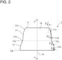
FIG. 2 is a front view of an earpiece-type electrode according to a first embodiment. -
FIG. 3 is a perspective view of the earpiece-type electrode according to the first embodiment. -
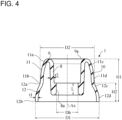
FIG. 4 is a sectional front view of the earpiece-type electrode according to the first embodiment. -
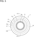
FIG. 5 is a plan view of the earpiece-type electrode according to the first embodiment. -
FIG. 6 is a front view of an earpiece-type electrode according to a second embodiment. -
FIG. 7 is a perspective view of the earpiece-type electrode according to the second embodiment. -
FIG. 8 is a sectional front view of the earpiece-type electrode according to the second embodiment. -
FIG. 9 is a plan view of the earpiece-type electrode according to the second embodiment. - The following describes various embodiments of the present invention with reference to the accompanying drawings. Reduction scales of the drawings are not necessarily precise, and some features are emphasized or omitted in the drawings in some cases.
- As illustrated in
FIG. 1 , an earpiece-type electrode 1 according to an embodiment is inserted into an externalauditory canal 2 of a human, s different mammal, or a bird. The earpiece-type electrode 1 is formed of electrically conductive rubber. The earpiece-type electrode 1 is electrically connected to a measurement device (not illustrated) when used. The measurement device measures a brain wave or a blood flow. - In a use example illustrated in
FIG. 1 , the earpiece-type electrode 1 is mechanically and electrically connected to a connection component 3. The connection component 3 is mechanically and electrically connected to the measurement device. The connection component 3 includes acylindrical component 4 made of metal. Thecylindrical component 4 is fitted into a distal end of aprotection tube 5 made of rubber. - A speaker 6 is fixed inside the
cylindrical component 4. Wires 6a are provided for causing the speaker 6 to generate a sound. The wires 6a extend through an inside of theprotection tube 5, and are electrically connected to the measurement device. - The
cylindrical component 4 includes a smaller-diametercylindrical portion 4a. Ahook 4b is formed at an end portion of the smaller-diametercylindrical portion 4a. Thehook 4b is an annular flange that expands outward in the radial direction. - The earpiece-
type electrode 1 includes aninner wall 8, adistal end wall 9, and anouter wall 10. The smaller-diametercylindrical portion 4a is fitted into theinner wall 8. Anannular hook 8a is formed at an end portion that is included in theinner wall 8 and that is located on an opposite side of thedistal end wall 9. Thehook 8a extends inward in the radial direction. Thehook 8a is caught by thehook 4b. In this manner, the earpiece-type electrode 1 is fixed to thecylindrical component 4, and is electrically connected to thecylindrical component 4. Thecylindrical component 4 is electrically connected to the measurement device vialead wires 4c extending through the inside of theprotection tube 5. Releasing the mutually caughthooks type electrode 1 to be detached from thecylindrical component 4. - In this use example, the earpiece-
type electrode 1 is used together with the speaker 6. In other words, the earpiece-type electrode 1 is used as an earpiece of a canal-type earphone. The speaker 6 generates a sound. The sound reaches a middle ear and an internal ear through an inner space of the smaller-diametercylindrical portion 4a, an inner space of theinner wall 8, and the externalauditory canal 2. The earpiece-type electrode 1 supplies electric current to the inner surface of the externalauditory canal 2 with which the earpiece-type electrode 1 contact. The earpiece-type electrode 1 measures a change in an electrical property, such as a change in electric potential or electric current, received from the externalauditory canal 2. The measurement device diagnoses a change in a brain wave or a blood flow, based on the change in the electrical property received from the externalauditory canal 2. Thereby, a mental state of a subject who has heard a particular sound can be estimated. - In this use example, the speaker 6 is connected to the measurement device via the wires 6a. However, the speaker 6 may be wirelessly connected to the measurement device.
- The speaker 6 may be omitted. The earpiece-
type electrode 1 may be used for supplying electric current to a skull to electrically stimulate a vestibule, without generating a sound. Alternatively, the earpiece-type electrode 1 may be used for measuring a brain wave or a blood flow, without generating a sound. - The electrically conductive rubber that is a material of the earpiece-
type electrode 1 includes one or both of particles and flakes. The particles and flakes are each an electrically conductive material. The rubber that is a matrix material is silicone rubber, for example. The electrically conductive material may be one of carbon black, gold (Au), platinum (Pt), silver (Ag), tungsten (W), molybdenum (Mo), copper (Cu), stainless steel, iron (Fe), and silver and silver chloride (Ag/AgCl), for example, or may be a mixture of materials selected from these. - As illustrated in
FIG. 2 to FIG. 5 , the earpiece-type electrode 1 according to a first embodiment has a three-dimensional shape that is rotationally symmetric about the central axis Ax.FIG. 4 is a sectional view taken along the line IV-IV inFIG. 2 andFIG. 5 . Since the earpiece-type electrode 1 has the rotationally symmetric shape, cutting the earpiece-type electrode 1 along any plane that includes the central axis Ax results in the same sectional view as that ofFIG. 4 . - The earpiece-
type electrode 1 includes theinner wall 8, thedistal end wall 9, and theouter wall 10. As illustrated inFIG. 1 , when the earpiece-type electrode 1 is attached to a living body, thedistal end wall 9 is oriented toward a deeper part of the externalauditory canal 2. - The
outer wall 10 contacts with the inner surface of the externalauditory canal 2. Theouter wall 10 includes a first truncated-cone wall portion 11 and a second truncated-cone wall portion 12. The first truncated-cone wall portion 11 and the second truncated-cone wall portion 12 each have a substantially truncated-cone shape. The first truncated-cone wall portion 11 and the second truncated-cone wall portion 12 may each have a completely truncated-cone shape. Alternatively, the first truncated-cone wall portion 11 and the second truncated-cone wall portion 12 may each have an incompletely truncated-cone shape, as in thewall portions FIG. 2 to FIG. 4 . Thus, the first truncated-cone wall portion 11 and the second truncated-cone wall portion 12 may have a shape that is recognized as truncated cone at a glance and that is suitable for being inserted into the externalauditory canal 2. In other words, the first truncated-cone wall portion 11 and the second truncated-cone wall portion 12 may each have even a shape of an umbrella or bowl whose radial-direction central portion is omitted. The truncated-cone wall portions - The first truncated-
cone wall portion 11 includes a firstaxial end portion 11a and a secondaxial end portion 11b. The secondaxial end portion 11b has a diameter larger than that of the firstaxial end portion 11a. The firstaxial end portion 11a is smoothly connected to thedistal end wall 9. The secondaxial end portion 11b is smoothly connected to the second truncated-cone wall portion 12. - As illustrated in
FIG. 2 , an inclination angle θ1 is larger than an inclination angle θ2. Here, the inclination angle θ1 is an inclination angle of afirst part 11c with respect to the central axis Ax. Thefirst part 11c is included in the first truncated-cone wall portion 11 and located on a side of the firstaxial end portion 11a. The inclination angle θ2 is an inclination angle of asecond part 11d with respect to the central axis Ax. Thesecond part 11d is included in the first truncated-cone wall portion 11 and located on a side of the secondaxial end portion 11b. The inclination angle θ1 of thefirst part 11c increases as a position approaches the firstaxial end portion 11a. Thus, the first truncated-cone wall portion 11 has an inclination angle that is an angle with respect to the central axis Ax and that increases as a position approaches the firstaxial end portion 11a. For this reason, the first truncated-cone wall portion 11 less irritates a subject when the earpiece-type electrode 1 is inserted into the externalauditory canal 2. - The second truncated-
cone wall portion 12 has a size larger than that of the first truncated-cone wall portion 11. The second truncated-cone wall portion 12 is arranged coaxially with the first truncated-cone wall portion 11. The second truncated-cone wall portion 12 includes a thirdaxial end portion 12a and a fourthaxial end portion 12b. The fourthaxial end portion 12b has a diameter larger than that of the thirdaxial end portion 12a. The thirdaxial end portion 12a is smoothly connected to the secondaxial end portion 11b. The fourthaxial end portion 12b is an end portion of the earpiece-type electrode 1, and is located on an opposite side of thedistal end wall 9. - As illustrated in
FIG. 2 , an inclination angle θ3 is larger than an inclination angle θ4. Here, the inclination angle θ3 is an inclination angle of athird part 12c with respect to the central axis Ax. Thethird part 12c is included in the second truncated-cone wall portion 12 and located on a side of the thirdaxial end portion 12a. The inclination angle θ4 is an inclination angle of afourth part 12d with respect to the central axis Ax. Thefourth part 12d is included in the second truncated-cone wall portion 12 and located on a side of the fourthaxial end portion 12b. Thefourth part 12d may have a cylindrical shape instead of a truncated-cone shape. In other words, the inclination angle θ4 may be zero. The inclination angle θ3 of thethird part 12c is larger than the inclination angle θ2 of thesecond part 11d. - As illustrated in
FIG. 4 , theinner wall 8 has a substantially truncated-cone shape in which a cross-sectional area on a side of thedistal end wall 9 is larger than a cross-sectional area on an opposite side. Theinner wall 8 is arranged on an inner side of theouter wall 10 and coaxially with theouter wall 10. Theannular hook 8a is formed at an end portion that is included in theinner wall 8 and that is on an opposite side of thedistal end wall 9. Thehook 8a extends inward in the radial direction. - The
distal end wall 9 has a substantially arc shape in a section including the central axis Ax. Thedistal end wall 9 is smoothly connected to theinner wall 8 and theouter wall 10. - Dimensions of the earpiece-
type electrode 1 are described with reference toFIG. 4 . A height H1 of the earpiece-type electrode 1 is in a range from 7 mm to 11 mm, for example. Here, the height H1 is a distance along the axial direction between the fourthaxial end portion 12b and adistal end surface 9a. A height H2 of the second truncated-cone wall portion 12 is in a range from 3 mm to 5 mm, for example. Here, the height H2 is a distance along the axial direction between the fourthaxial end portion 12b and the thirdaxial end portion 12a. - An outer diameter D1 of the earpiece-
type electrode 1 is in a range from 10 mm to 14 mm, for example. Here, the outer diameter D1 is an outer diameter of the fourthaxial end portion 12b. An outer diameter D2 of the first truncated-cone wall portion 11 is in a range from 9 mm to 12 mm, for example. Here, the outer diameter D2 is an outer diameter of the thirdaxial end portion 12a, and is also an outer diameter of the secondaxial end portion 11b. - An inner diameter Dh of the
hook 8a is in a range from 3 mm to 5 mm, for example. An axial length L of thehook 8a is in a range from 1 mm to 3 mm, for example. - A thickness t1 of the
outer wall 10 is in a range from 0.3 mm to 0.6 mm, for example. A thickness t2 of theinner wall 8 is in a range from 0.5 mm to 0.8 mm, for example. The thickness t1 is preferably smaller than the thickness t2. In this case, theinner wall 8 has a higher rigidity, and thus prevents the earpiece-type electrode 1 from buckling. Thedistal end wall 9 and theouter wall 10 each have a lower rigidity, and thus deform in such a way as to follow a shape and size of the externalauditory canal 2. For this reason, thedistal end wall 9 and theouter wall 10 reduce irritation inflicted on a subject. - The earpiece-
type electrode 1 according to the present embodiment includes the two truncated-cone wall portions type electrode 1 can properly fit into the externalauditory canals 2 having various shapes and sizes. Thus, the earpiece-type electrode 1 stably contacts with the inner surface of the externalauditory canal 2 over a wide area at a certain degree of contact pressure. Necessity of preparing the earpiece-type electrodes 1 of a large number of different sizes can be reduced. - When the earpiece-
type electrode 1 is attached to a living body, the first truncated-cone wall portion 11 is oriented toward a deeper part of the externalauditory canal 2 in such a way as to be closer to the deeper part of the externalauditory canal 2 than second truncated-cone wall portion 12. Thefirst part 11c of the first truncated-cone wall portion 11 is oriented toward the deeper part of the externalauditory canal 2 in such a way as to be closer to the deeper part of the externalauditory canal 2 than thesecond part 11d. As illustrated inFIG. 2 , the inclination angle θ1 of thefirst part 11c with respect to the central axis Ax is larger than the inclination angle θ2 of thesecond part 11d. Accordingly, the first truncated-cone wall portion 11 can be smoothly inserted into the externalauditory canal 2. When a diameter of the externalauditory canal 2 is small, thesecond part 11d is likely to come into surface contact with an inner surface of the externalauditory canal 2 over a wide contact area. - When the earpiece-
type electrode 1 is attached to a living body, thethird part 12c of the second truncated-cone wall portion 12 is oriented toward a deeper part of the externalauditory canal 2 in such a way as to be closer to the deeper part of the externalauditory canal 2 than thefourth part 12d. The inclination angle θ3 of thethird part 12c with respect to the central axis Ax is larger than the inclination angle θ2 of thesecond part 11d, and is larger than the inclination angle θ4 of thefourth part 12d. Thus, when a diameter of the externalauditory canal 2 is large, the second truncated-cone wall portion 12 can be smoothly inserted into the externalauditory canal 2. One or both of thethird part 12c and thefourth part 12d are likely to come into surface contact with an inner surface of the externalauditory canal 2 over a wide contact area. - As illustrated in
FIG. 6 to FIG. 9 , an earpiece-type electrode 20 according to a second embodiment also has a three-dimensional shape that is rotationally symmetric about the central axis Ax.FIG. 8 is a sectional view taken along the line VIII-VIII inFIG. 6 andFIG. 9 . Since the earpiece-type electrode 20 has the rotationally symmetric shape, cutting the earpiece-type electrode 20 along any plane that includes the central axis Ax results in the same sectional view as that ofFIG. 8 . - The earpiece-
type electrode 20 includes features in common with the earpiece-type electrode 1 according to the first embodiment. Accordingly, description of these features is omitted. - The
outer wall 10 in the present embodiment includes the first truncated-cone wall portion 11, the second truncated-cone wall portion 12, and a third truncated-cone wall portion 13. The third truncated-cone wall portion 13 has a size larger than that of the second truncated-cone wall portion 12. The third truncated-cone wall portion 13 has a substantially truncated-cone shape. The third truncated-cone wall portion 13 is arranged coaxially with the first truncated-cone wall portion 11 and the second truncated-cone wall portion 12. The third truncated-cone wall portion 13 includes a fifthaxial end portion 13a and a sixthaxial end portion 13b. The sixthaxial end portion 13b has a diameter larger than that of the fifthaxial end portion 13a. The fifthaxial end portion 13a is smoothly connected to the fourthaxial end portion 12b. The sixthaxial end portion 13b is an end portion of the earpiece-type electrode 1, and is located on an opposite side of thedistal end wall 9. - Dimensions of the earpiece-
type electrode 20 are described with reference toFIG. 8 . A height H1 of the earpiece-type electrode 20 is in a range from 9 mm to 13 mm, for example. Here, the height H1 is a distance along the axial direction between the sixthaxial end portion 13b and thedistal end surface 9a. A height H3 of the third truncated-cone wall portion 13 is in a range from 2 mm to 4 mm, for example. Here, the height H3 is a distance along the axial direction between the sixthaxial end portion 13b and the fifthaxial end portion 13a. The height H2 of the second truncated-cone wall portion 12 is in a range from 3 mm to 5 mm, for example. Here, the height H2 is a distance along the axial direction between the fourthaxial end portion 12b and the thirdaxial end portion 12a. - An outer diameter D1 of the earpiece-
type electrode 20 is in a range from 11 mm to 15 mm, for example. Here, the outer diameter D1 is an outer diameter of the sixthaxial end portion 13b. The outer diameter D2 of the first truncated-cone wall portion 11 is in a range from 9 mm to 12 mm, for example. Here, the outer diameter D2 is an outer diameter of the thirdaxial end portion 12a, and is also an outer diameter of the secondaxial end portion 11b. An outer diameter D3 of the second truncated-cone wall portion 12 is in a range from 10 mm to 14 mm, for example. Here, the outer diameter D3 is an outer diameter of the fifthaxial end portion 13a, and is also an outer diameter of the fourthaxial end portion 12b. - An inner diameter Dh of the
hook 8a is in a range from 3 mm to 5 mm, for example. An axial length L of thehook 8a is in arange 1 mm to 3 mm, for example. - A thickness t1 of the
outer wall 10 is in a range from 0.3 mm to 0.6 mm, for example. A thickness t2 of theinner wall 8 is in a range from 0.5 mm to 0.8 mm, for example. The thickness t1 is preferably smaller than the thickness t2. In this case, theinner wall 8 has a higher rigidity, and thus prevents the earpiece-type electrode 20 from buckling. Thedistal end wall 9 and theouter wall 10 each have a lower rigidity, and thus deform in such a way as to follow a shape and size of the externalauditory canal 2. For this reason, thedistal end wall 9 and theouter wall 10 reduce irritation inflicted on a subject. - The earpiece-
type electrode 20 according to the present embodiment includes the three truncated-cone walls type electrode 20 can properly fit into the externalauditory canals 2 having various shapes and sizes. Thus, the earpiece-type electrode 20 stably contacts with the inner surface of the externalauditory canal 2 over a wide area at a certain degree of contact pressure. Necessity of preparing the earpiece-type electrodes 20 of a large number of different sizes can be reduced. - When the earpiece-
type electrode 20 is attached to a living body, the first truncated-cone wall portion 11 is oriented toward a deeper part of the externalauditory canal 2 in such a way as to be closer to the deeper part of the externalauditory canal 2 than second truncated-cone wall portion 12. Thefirst part 11c of the first truncated-cone wall portion 11 is oriented toward the deeper part of the externalauditory canal 2 in such a way as to be closer to the deeper part of the externalauditory canal 2 than thesecond part 11d. As illustrated inFIG. 6 , the inclination angle θ1 of thefirst part 11c with respect to the central axis Ax is larger than the inclination angle θ2 of thesecond part 11d. Accordingly, the first truncated-cone wall portion 11 can be smoothly inserted into the externalauditory canal 2. When a diameter of the externalauditory canal 2 is small, thesecond part 11d is likely to come into surface contact with an inner surface of the externalauditory canal 2 over a wide contact area. - The inclination angle θ1 of the
first part 11c increases as a position approaches the firstaxial end portion 11a. Thus, the first truncated-cone wall portion 11 has an inclination angle that is an angle with respect to the central axis Ax and that increases as a position approaches the firstaxial end portion 11a. For this reason, the first truncated-cone wall portion 11 less irritates a subject when the earpiece-type electrode 1 is inserted into the externalauditory canal 2. - When the earpiece-
type electrode 20 is attached to a living body, thethird part 12c of the second truncated-cone wall portion 12 is oriented toward a deeper part of the externalauditory canal 2 in such a way as to be closer to the deeper part of the externalauditory canal 2 than thefourth part 12d. The inclination angle θ3 of thethird part 12c with respect to the central axis Ax is larger than the inclination angle θ2 of thesecond part 11d, and is larger than the inclination angle θ4 of thefourth part 12d. Thus, when a diameter of the externalauditory canal 2 is large, the second truncated-cone wall portion 12 can be smoothly inserted into the externalauditory canal 2. One or both of thethird part 12c and thefourth part 12d are likely to come into surface contact with an inner surface of the externalauditory canal 2 over a wide contact area. Thefourth part 12d may have a cylindrical shape instead of a truncated-cone shape. In other words, the inclination angle θ4 may be zero. - As illustrated in
FIG. 6 , an inclination angle θ5 is larger than an inclination angle θ6. Here, the inclination angle θ5 is an inclination angle of afifth part 13c with respect to the central axis Ax. Thefifth part 13c is included in the third truncated-cone wall portion 13 and located on a side of the fifthaxial end portion 13a. The inclination angle θ6 is an inclination angle of asixth part 13d with respect to the central axis Ax. Thesixth part 13d is included in the third truncated-cone wall portion 13 and located on a side of the sixthaxial end portion 13b. The inclination angle θ5 of thefifth part 13c is larger than the inclination angle θ4 of thefourth part 12d. Thus, when a diameter of the externalauditory canal 2 is still larger, the third truncated-cone wall portion 13 can be smoothly inserted into the externalauditory canal 2, and one or both of thefifth part 13c and thesixth part 13d are likely to come into surface contact with an inner surface of the externalauditory canal 2 over a wide contact area. Thesixth part 13d may have a cylindrical shape instead of a truncated-cone shape. In other words, the inclination angle θ6 may be zero. - Although the embodiments are described above, the present invention is not limited to these.
- For example, the
outer wall 10 may include four or more truncated-cone portions. - The
inner wall 8, thedistal end wall 9, and theouter wall 10 may be formed of the same material, or may be formed of different materials. For example, a matrix material used as a rubber material of each of thedistal end wall 9 and theouter wall 10 that contact with a living body may be softer than a matrix material of theinner wall 8 that does not contact with a living body. In this case, theinner wall 8 has a higher rigidity, and thus prevents the earpiece-type electrode 1 from buckling. Thedistal end wall 9 and theouter wall 10 each have a lower rigidity, and thus deform in such a way as to follow a shape and size of the externalauditory canal 2. For this reason, thedistal end wall 9 and theouter wall 10 reduce irritation inflicted on a subject. - The earpiece-
type electrodes FIG. 1 ). In this case, thedistal end wall 9 does not need to include an opening through which a sound can propagate to an middle ear and an internal ear of a subject. The earpiece-type electrodes inner wall 8. -
- 1, 20
- earpiece-type electrode
- 2
- external auditory canal
- 8
- inner wall
- 9
- distal end wall
- 10
- outer wall
- 11
- first truncated-cone wall portion
- 11a
- first axial end portion
- 11b
- second axial end portion
- 11c
- first part
- 11d
- second part
- 12
- second truncated-cone wall portion
- 12a
- third axial end portion
- 12b
- fourth axial end portion
- 12c
- third part
- 12d
- fourth part
- 13
- third truncated-cone wall portion
- 13a
- fifth axial end portion
- 13b
- sixth axial end portion
- 13c
- fifth part
- 13d
- sixth part
Claims (6)
- An earpiece-type electrode to be inserted into an external auditory canal, comprising:a first truncated-cone wall portion formed of electrically conductive rubber and having a substantially truncated-cone shape, the first truncated-cone wall portion includinga first axial end portion anda second axial end portion larger in diameter than the first axial end portion; anda second truncated-cone wall portion formed of electrically conductive rubber, larger in size than the first truncated-cone wall portion, having a substantially truncated-cone shape, and arranged coaxially with the first truncated-cone wall portion, the second truncated-cone wall portion includinga third axial end portion connected to the second axial end portion, anda fourth axial end portion larger in diameter than the third axial end portion.
- The earpiece-type electrode according to claim 1, wherein
the first truncated-cone wall portion and the second truncated-cone wall portion each have a shape rotationally symmetric about a central axis. - The earpiece-type electrode according to claim 1 or 2, whereinthe first truncated-cone wall portion includes a first part located on a side of the first axial end portion and a second part located on a side of the second axial end portion, and an inclination angle of the first part with respect to a central axis is larger than an inclination angle of the second part with respect to the central axis, andthe second truncated-cone wall portion includes a third part located on a side of the third axial end portion and a fourth part located on a side of the fourth axial end portion, and an inclination angle of the third part with respect to the central axis is larger than the inclination angle of the second part, and is larger than an inclination angle of the fourth part with respect to the central axis.
- The earpiece-type electrode according to claim 3, wherein
the inclination angle in the first part increases as a position approaches the first axial end portion. - The earpiece-type electrode according to any one of claims 1 to 4, further comprising:
a third truncated-cone wall portion formed of electrically conductive rubber, larger in size than the second truncated-cone wall portion, having a substantially truncated-cone shape, and arranged coaxially with the second truncated-cone wall portion, the third truncated-cone wall portion includinga fifth axial end portion connected to the fourth axial end portion, anda sixth axial end portion larger in diameter than the fifth axial end portion. - The earpiece-type electrode according to claim 5, whereinthe first truncated-cone wall portion includes a first part located on a side of the first axial end portion and a second part located on a side of the second axial end portion, and an inclination angle of the first part with respect to a central axis is larger than an inclination angle of the second part with respect to the central axis,the second truncated-cone wall portion includes a third part located on a side of the third axial end portion and a fourth part located on a side of the fourth axial end portion, and an inclination angle of the third part with respect to the central axis is larger than the inclination angle of the second part, and is larger than an inclination angle of the fourth part with respect to the central axis, andthe third truncated-cone wall portion includes a fifth part located on a side of the fifth axial end portion and a sixth part located on a side of the sixth axial end portion, and an inclination angle of the fifth part with respect to the central axis is larger than the inclination angle of the fourth part, and is larger than an inclination angle of the sixth part with respect to the central axis.
Applications Claiming Priority (2)
| Application Number | Priority Date | Filing Date | Title |
|---|---|---|---|
| JP2022110766 | 2022-07-08 | ||
| PCT/JP2023/024537 WO2024009920A1 (en) | 2022-07-08 | 2023-07-03 | Earpiece-type electrode |
Publications (1)
| Publication Number | Publication Date |
|---|---|
| EP4552573A1 true EP4552573A1 (en) | 2025-05-14 |
Family
ID=89453448
Family Applications (1)
| Application Number | Title | Priority Date | Filing Date |
|---|---|---|---|
| EP23835452.6A Pending EP4552573A1 (en) | 2022-07-08 | 2023-07-03 | Earpiece-type electrode |
Country Status (5)
| Country | Link |
|---|---|
| US (1) | US20250359796A1 (en) |
| EP (1) | EP4552573A1 (en) |
| JP (1) | JP7622301B2 (en) |
| CN (1) | CN119031883A (en) |
| WO (1) | WO2024009920A1 (en) |
Family Cites Families (5)
| Publication number | Priority date | Publication date | Assignee | Title |
|---|---|---|---|---|
| JP5481749B2 (en) | 2010-04-12 | 2014-04-23 | 日本電信電話株式会社 | External ear canal insertion type electrode and method for producing external ear canal insertion type electrode |
| JP2019024758A (en) * | 2017-07-27 | 2019-02-21 | 富士ゼロックス株式会社 | Electrode and electroencephalogram measurement device |
| US20210000370A1 (en) * | 2019-07-02 | 2021-01-07 | X Development Llc | In-Ear EEG Sensor Using Malleable Form Fitting Foam |
| JP2021013058A (en) * | 2019-07-03 | 2021-02-04 | 株式会社発明屋 | Sound plug |
| JP2022059147A (en) * | 2020-10-01 | 2022-04-13 | 株式会社Agama-X | Biological information measurement system |
-
2023
- 2023-07-03 EP EP23835452.6A patent/EP4552573A1/en active Pending
- 2023-07-03 JP JP2024532104A patent/JP7622301B2/en active Active
- 2023-07-03 US US18/881,454 patent/US20250359796A1/en active Pending
- 2023-07-03 CN CN202380034102.2A patent/CN119031883A/en active Pending
- 2023-07-03 WO PCT/JP2023/024537 patent/WO2024009920A1/en not_active Ceased
Also Published As
| Publication number | Publication date |
|---|---|
| JPWO2024009920A1 (en) | 2024-01-11 |
| CN119031883A (en) | 2024-11-26 |
| JP7622301B2 (en) | 2025-01-27 |
| WO2024009920A1 (en) | 2024-01-11 |
| US20250359796A1 (en) | 2025-11-27 |
Similar Documents
| Publication | Publication Date | Title |
|---|---|---|
| JP5481749B2 (en) | External ear canal insertion type electrode and method for producing external ear canal insertion type electrode | |
| US20240305920A1 (en) | Open Audio Device | |
| US8073175B2 (en) | Behind-the-ear type hearing aid | |
| CN102469950B (en) | Earplugs with Surface Electrodes | |
| US10212525B2 (en) | Universal earpiece | |
| US7340075B2 (en) | Otoplasty for behind-the-ear (BTE) hearing aids | |
| US7233676B2 (en) | Otoplasty for behind-the-ear (BTE) hearing aids | |
| CN105980001B (en) | Electrode lead with integrated attachment mechanism | |
| CN110167440A (en) | Universal ear device with electrodes | |
| CN108055822A (en) | Ear canal plugs for detecting bioelectrical signals | |
| EP3698557B1 (en) | Method of making a hearing device and a respective hearing device | |
| CN109922859B (en) | Electrode array and cochlear implant including the same | |
| JP2024011561A (en) | Earpiece-type electrode | |
| JP7856337B2 (en) | Biological information measuring device | |
| JP2018186934A (en) | Biological signal detection device and brain wave measurement method | |
| US20230389847A1 (en) | Electrode system for rubber ear tips with conductivity from n-doped silicone or conductive filaments in mixture for electroencephalography | |
| US20250359796A1 (en) | Earpiece-type electrode | |
| JP2024011560A (en) | Earpiece-type electrode | |
| EP4037295A1 (en) | Ear level part for a hearing device | |
| JP2024046663A (en) | EEG measurement device | |
| US11825258B2 (en) | Headset assembly using bone conduction | |
| EP4011097B1 (en) | Connector tip with bristles for hearing instruments | |
| JPH05300207A (en) | One-ear mount type handset | |
| EP1151633A1 (en) | Methods and apparatus for fitting hearing device tips | |
| JP2023152839A (en) | Biopotential measurement system |
Legal Events
| Date | Code | Title | Description |
|---|---|---|---|
| STAA | Information on the status of an ep patent application or granted ep patent |
Free format text: STATUS: THE INTERNATIONAL PUBLICATION HAS BEEN MADE |
|
| PUAI | Public reference made under article 153(3) epc to a published international application that has entered the european phase |
Free format text: ORIGINAL CODE: 0009012 |
|
| STAA | Information on the status of an ep patent application or granted ep patent |
Free format text: STATUS: REQUEST FOR EXAMINATION WAS MADE |
|
| 17P | Request for examination filed |
Effective date: 20241025 |
|
| AK | Designated contracting states |
Kind code of ref document: A1 Designated state(s): AL AT BE BG CH CY CZ DE DK EE ES FI FR GB GR HR HU IE IS IT LI LT LU LV MC ME MK MT NL NO PL PT RO RS SE SI SK SM TR |
|
| DAV | Request for validation of the european patent (deleted) | ||
| DAX | Request for extension of the european patent (deleted) |