EP4552532A1 - Slide rail assembly - Google Patents
Slide rail assembly Download PDFInfo
- Publication number
- EP4552532A1 EP4552532A1 EP24174320.2A EP24174320A EP4552532A1 EP 4552532 A1 EP4552532 A1 EP 4552532A1 EP 24174320 A EP24174320 A EP 24174320A EP 4552532 A1 EP4552532 A1 EP 4552532A1
- Authority
- EP
- European Patent Office
- Prior art keywords
- rail
- handle
- state
- elastic
- feature
- Prior art date
- Legal status (The legal status is an assumption and is not a legal conclusion. Google has not performed a legal analysis and makes no representation as to the accuracy of the status listed.)
- Pending
Links
Images








Classifications
-
- A—HUMAN NECESSITIES
- A47—FURNITURE; DOMESTIC ARTICLES OR APPLIANCES; COFFEE MILLS; SPICE MILLS; SUCTION CLEANERS IN GENERAL
- A47B—TABLES; DESKS; OFFICE FURNITURE; CABINETS; DRAWERS; GENERAL DETAILS OF FURNITURE
- A47B88/00—Drawers for tables, cabinets or like furniture; Guides for drawers
- A47B88/50—Safety devices or the like for drawers
-
- A—HUMAN NECESSITIES
- A47—FURNITURE; DOMESTIC ARTICLES OR APPLIANCES; COFFEE MILLS; SPICE MILLS; SUCTION CLEANERS IN GENERAL
- A47B—TABLES; DESKS; OFFICE FURNITURE; CABINETS; DRAWERS; GENERAL DETAILS OF FURNITURE
- A47B88/00—Drawers for tables, cabinets or like furniture; Guides for drawers
- A47B88/40—Sliding drawers; Slides or guides therefor
- A47B88/473—Braking devices, e.g. linear or rotational dampers or friction brakes; Buffers; End stops
-
- A—HUMAN NECESSITIES
- A47—FURNITURE; DOMESTIC ARTICLES OR APPLIANCES; COFFEE MILLS; SPICE MILLS; SUCTION CLEANERS IN GENERAL
- A47B—TABLES; DESKS; OFFICE FURNITURE; CABINETS; DRAWERS; GENERAL DETAILS OF FURNITURE
- A47B88/00—Drawers for tables, cabinets or like furniture; Guides for drawers
- A47B88/40—Sliding drawers; Slides or guides therefor
- A47B88/483—Sliding drawers; Slides or guides therefor with single extensible guides or parts
-
- A—HUMAN NECESSITIES
- A47—FURNITURE; DOMESTIC ARTICLES OR APPLIANCES; COFFEE MILLS; SPICE MILLS; SUCTION CLEANERS IN GENERAL
- A47B—TABLES; DESKS; OFFICE FURNITURE; CABINETS; DRAWERS; GENERAL DETAILS OF FURNITURE
- A47B88/00—Drawers for tables, cabinets or like furniture; Guides for drawers
- A47B88/40—Sliding drawers; Slides or guides therefor
- A47B88/423—Fastening devices for slides or guides
- A47B2088/4235—Fastening devices for slides or guides having a latch mechanism coupling or disconnecting a drawer with drawer side slide from the rest of the slide members
-
- A—HUMAN NECESSITIES
- A47—FURNITURE; DOMESTIC ARTICLES OR APPLIANCES; COFFEE MILLS; SPICE MILLS; SUCTION CLEANERS IN GENERAL
- A47B—TABLES; DESKS; OFFICE FURNITURE; CABINETS; DRAWERS; GENERAL DETAILS OF FURNITURE
- A47B2210/00—General construction of drawers, guides and guide devices
- A47B2210/0002—Guide construction for drawers
- A47B2210/0016—Telescopic drawer slide latch device
-
- A—HUMAN NECESSITIES
- A47—FURNITURE; DOMESTIC ARTICLES OR APPLIANCES; COFFEE MILLS; SPICE MILLS; SUCTION CLEANERS IN GENERAL
- A47B—TABLES; DESKS; OFFICE FURNITURE; CABINETS; DRAWERS; GENERAL DETAILS OF FURNITURE
- A47B2210/00—General construction of drawers, guides and guide devices
- A47B2210/0002—Guide construction for drawers
- A47B2210/0018—Buffers, stop blocks or latches for single drawer slides
Definitions
- the present invention is related to a slide rail assembly.
- US patent number US 10,631 , 639B2 discloses a slide rail assembly comprising a first rail, a second rail, a blocking member and an operating member.
- the second rail and the first rail are longitudinally movable relative to each other.
- the blocking member is coupled to the first rail.
- the operating member can enter a predetermined state with respect to the second rail. When the second rail is located at a predetermined position with respect to the first rail, the operating member is in the predetermined state and blocked by the blocking member to prevent the second rail from displacement from the predetermined position in a predetermined direction. When the operating member is not in the predetermined state and hence not blocked by the blocking member, the second rail can be displaced from the predetermined position in the predetermined direction.
- the operating member is pivotally connected to the second rail through a shaft, and the shaft is arranged in a direction substantially identical to a lateral direction (or transverse direction) of the second rail. As such, when the operating member is operated by a user, the operating member is rotated to move along a height direction of the second rail.
- the present invention aims at providing a slide rail assembly.
- the claimed slide rail assembly comprises a first rail, a second rail and a handle.
- the second rail is movable relative to the first rail.
- the handle is pivoted to the second rail through a shaft member and movable relative to the second rail to switch between a first state and a second state.
- the shaft member is arranged in a direction substantially identical to a moving direction of the second rail relative to the first rail.
- a slide rail assembly 20 comprises a first rail 22, a second rail 24 and a handle 26 according to a first embodiment of the present invention.
- the slide rail assembly 20 further comprises a third rail 28 movably mounted between the first rail 22 and the second rail 24.
- the second rail 24 is located at a retracted position R relative to the first rail 22.
- the second rail 24 is longitudinally movable relative to the first rail 22.
- the X axis is a longitudinal direction (or a length direction or a moving direction of the slide rail)
- the Y axis is a transverse direction (or a lateral direction of the slide rail)
- the Z axis is a vertical direction (or a height direction of the slide rail).
- the handle 26 is movable relative to the second rail 24. More particularly, the handle 26 is pivoted to the second rail 24 through a shaft member 30, such that the handle 26 is movable to switch between a first state S1 (as shown in FIG. 1 ) and a second state S2 (as shown in FIG. 2 ).
- the shaft member 30 is arranged in a direction substantially identical to a moving direction of the second rail 24 relative to the first rail 22. In other words, the shaft member 30 is arranged in a direction substantially identical to a length direction of the second rail 24 (or the longitudinal direction or the X axis direction).
- a user can apply a force F to the handle 26 along an opening direction D1 (for example, the user can easily hold the handle 26 in the second state S2 to apply the force F as shown in FIG. 2 ), such that the second rail 24 can be easily pulled out relative to the first rail 22 along the opening direction D1.
- the handle 26 when the handle 26 is in the first state S1 (as shown in FIG. 1 ), the handle 26 is arranged in a direction substantially identical to a height direction of the second rail 24 (or the Z axis direction).
- the handle 26 when the handle 26 is in the second state S2 (as shown in FIG. 2 ), the handle 26 is arranged in a direction substantially identical to a transverse direction of the second rail 24 (or the Y axis direction).
- the moving direction of the second rail 24 relative to the first rail 22, the height direction of the second rail 24 and the transverse direction of the second rail 24 are perpendicular to each other.
- the second rail 24 has an outer side L1 and an inner side L2 opposite to each other.
- the outer side L1 is adjacent to and faces toward the first rail 22 (or the third rail 28).
- the first rail 22 has a first end part 22a and a second end part 22b opposite to each other, such as a front end part and a rear end part.
- the second rail 24 has a first end part 24a and a second end part 24b opposite to each other, such as a front end part and a rear end part.
- the first rail 22 is arranged with a bracket 25.
- the bracket 25 is connected (such as fixedly connected) to the first rail 22 to be seen as a part of the first rail 22.
- the first rail 22 comprises a blocking part 19.
- the blocking part 19 is arranged on one of the first rail 22 and the bracket 25.
- the blocking part 19 is arranged on an extension component 17 of the bracket 25, and the blocking part 19 is adjacent to the first end part 22a of the first rail 22.
- the handle 26 is rotatable to switch between the first state S1 (as shown in FIG. 3 ) and the second state S2 (as shown in FIG. 4 ) through the shaft member 30.
- the handle 26 comprises a first end 26a, a second end 26b and an operating section 26c connected between the first end 26a and the second end 26b (as shown in FIG. 3 and FIG. 3A ).
- the shaft member 30 is adjacent to the first end 26a of the handle 26.
- the handle 26 is pivoted to a connecting component 32 on the second rail 24 through the shaft member 30.
- the connecting component 32 is connected (such as fixedly connected) to the second rail 24 to be seen as a part of the second rail 24.
- the operating section 26c of the handle 26 is configured to be held by the user to pull out the second rail 24 from the retracted position R along the opening direction D1 relative to the first rail 22 (please also refer to FIG. 4 and FIG. 2 ).
- the slide rail assembly 20 further comprises an elastic member 33 (as shown in FIG. 3A ) .
- the handle 26 is configured to be held at the first state S1 in response to an elastic force of the elastic member 33.
- the elastic member 33 can be a torsion spring, or other object with elasticity, but the present invention is not limited thereto.
- the elastic member 33 comprise a first elastic section 33a, a second elastic section 33b (as shown in FIG. 4A ) and a middle section 33c (as shown in FIG. 3A ) connected between the first elastic section 33a and the second elastic section 33b.
- the middle section 33c is arranged on a main body of the shaft member 30.
- the first elastic section 33a is configured to abut against the handle 26, and the second elastic section 33b is configured to abut against the connecting component 32 on the second rail 24; or the second elastic section 33b is configured to abut against the handle 26, and the first elastic section 33a is configured to abut against the connecting component 32 on the second rail 24.
- the slide rail assembly 20 further comprises a locking member 34 movably mounted on the second rail 24.
- the locking member 34 is pivoted to the connecting component 32 on the second rail 24 through an auxiliary shaft 36.
- the locking member 34 is pivoted to the second rail 24.
- the auxiliary shaft 36 is arranged in a direction substantially identical to the transverse direction of the second rail 24 (or the Y axis direction).
- a locking part 38 of the locking member 34 is configured to be blocked by the blocking part 19 in order to prevent the second rail 24 from being moved away from the retracted position R relative to the first rail 22 (as shown in FIG. 3 ).
- the handle 26 comprises a supporting feature 40.
- the supporting feature 40 has a guiding part (such as an inclined surface or an arc surface).
- the handle 26 is configured to support the locking member 34 through the supporting feature 40, in order to hold the locking member 38 to be blocked by the blocking part 19 (as shown in FIG. 3 ).
- the handle 26 further comprises a guiding feature 42.
- the guiding feature 42 has an inclined surface or an arc surface.
- the guiding feature 42 and the supporting feature 40 together define a predetermined space K configured to accommodate an extension part 44 of the locking member 34, such that the extension part 44 can be supported by the supporting feature 40 of the handle 26.
- the auxiliary shaft 36 is located between the locking part 38 and the extension part 44 (as shown in FIG. 3 ).
- the handle 26 is configured to move the extension part 44 of the locking member 34 through the guiding feature 42 (as shown in FIG. 3 and FIG. 3A ), in order to drive the locking member 34 to rotate a predetermined angle.
- the supporting feature 40 of the handle 26 no longer supports the extension part 44 of the locking member 34, such that the locking part 38 of the locking member 34 is no longer blocked by the blocking part 19, in order to allow the second rail 24 to be moved away from the retracted position R along the opening direction D1 relative to the first rail 22 (as shown in FIG. 4 and FIG. 4A ).
- the first rail 22 is arranged with an auxiliary structure 46.
- the auxiliary structure 46 is arranged on the bracket 25 of the first rail 22, and the auxiliary structure 46 is a pin, but the present invention is not limited thereto.
- the auxiliary structure 46 is laterally (transversely) protruded relative to the first rail 22.
- the second rail 24 is arranged with an auxiliary elastic member 48.
- the auxiliary elastic member 48 is arranged with a first predetermined feature 50
- the handle 26 is arranged with a second predetermined feature 52.
- the first predetermined feature 50 and the second predetermined feature 52 are a combination of a protruded part and a recessed part (or a structure formed with a space or a hole) .
- the first predetermined feature 50 is a fixing bolt with an extension protruded part 50a
- the second predetermined feature 52 is a structure formed with a hole, but the present invention is not limited thereto.
- the auxiliary elastic member 48 is connected to the connecting component 32 on the second rail 24 in the present embodiment.
- the auxiliary structure 46 and the auxiliary elastic member 48 abut against each other, such that the auxiliary elastic member 48 is configured to accumulate an auxiliary elastic force f, and the first predetermined feature 50 (the extension protruded part 50a of the fixing bolt) is not engaged with the second predetermined feature 52 (the hole of the structure) as shown in FIG. 4 and FIG. 4A .
- the first predetermined feature 50 (the extension protruded part 50a of the fixing bolt) is inserted into the second predetermined feature 52 (the hole of the structure) in order to hold the handle 26 in the second state S2 (as shown in FIG. 5 and FIG. 5A ).
- the elastic member 33 is configured to be held in a state of accumulating an elastic force through mutually engaging the first predetermined feature 50 with the second predetermined feature 52.
- one end of the auxiliary elastic member 48 is arranged with a guiding section 54 (such as an inclined surface or an arc surface).
- a guiding section 54 such as an inclined surface or an arc surface.
- the handle 26 is driven to move to switch from the second state S2 to the first state S1 in response to the elastic force being released by the elastic member 33.
- the supporting feature 40 of the handle 26 is configured to contact the extension part 44 of the locking member 34 through the guiding part (such as an inclined surface or an arc surface), so as to drive the locking member 34 to move back to the state being blocked by the blocking part 19.
- the second rail 24 is locked at the retracted position R relative to the first rail 22 again (as shown in FIG. 3 and FIG. 3A ).
- the slide rail assembly 20 is mounted to a rack 56 (or a cabinet).
- the first rail 22 is configured to be mounted to at least one post of the rack 56 through the bracket 25, and the second rail 24 is configured to carry a carried object (not shown).
- some part of the rack 56 may block at an outer side of the slide rail assembly 20.
- the handle 26 provided in the present embodiment is configured to be moved toward an inner side of the slide rail assembly 20 (such as toward the inner side L2 of the second rail 24) by the user to switch from the first state S1 to the second state S2, such that the second rail 24 can be easily pulled out along the opening direction D1 relative to the first rail 22 without being affected by the wall part 58.
- the operating section 26c of the handle 26 is extended beyond the inner side L2 of the second rail 24 by a predetermined distance M, and the user can hold the operating section 26c of the handle 26 with his hand to apply a force F along the opening direction D1, so as to easily and conveniently pull out the second rail 24 from the retracted position R along the opening direction D1 relative to the first rail 22.
- FIG. 8 to FIG. 12 show a slide rail assembly 200 according to a second embodiment of the present invention.
- the difference between the slide rail assembly 200 of the second embodiment and the slide rail assembly 20 of the first embodiment substantially lies in structural design of the handle 201.
- the handle 201 comprises a first end 201a, a second end 201b and an operating section 201c connected between the first end 201a and the second end 201b (as shown in FIG. 8 and FIG. 9 ). Similar to the first embodiment, the handle 201 is pivoted to a second rail 204 through a shaft member 203, such that the handle 201 is movable to switch between a first state S1' (as shown in FIG. 8 ) and a second state S2' (as shown in FIG. 9 ).
- the handle 201 is arranged with a driving part 206, such as a protrusion (as shown in FIG. 10 ) .
- a first end 204a of the second rail 204 is arranged with a connecting component 207 (as shown in FIG. 8 or FIG. 9 ), and the handle 201 is pivotally connected to the connecting component 207 on the second rail 204 through the shaft member 203.
- the connecting component 207 is connected (such as fixedly connected) to the second rail 204 to be seen as a part of the second rail 204.
- the connecting component 207 comprises a casing 208, and the casing 208 accommodates a locking member 210 (as shown in FIG. 11 ).
- the locking member 210 is movably mounted on the second rail 204.
- the locking member 210 is pivoted to the connecting component 207 of the second rail 204 through an auxiliary shaft 212.
- the auxiliary shaft 212 of the second embodiment is arranged in a direction substantially identical to a height direction of the second rail 204 (or the aforementioned Z-axis direction).
- the slide rail assembly 200 further comprises an elastic member 214 configured to provide an elastic force to the locking member 210.
- the elastic member 214 can be an elastic piece, or other type of component with elasticity. Configuration and structure of the elastic member 214 is not limited.
- the elastic member 214 comprises an elastic part 215 configured to provide the elastic force to the locking member 210, such that a locking part 216 of the locking member 210 can be held in a state of being blocked by a blocking section 219 (or a blocking wall) of a blocking part 218 of a first rail 202 (or a bracket of the first rail 202), in order to prevent the second rail 204 from being moved away from the retracted position R relative to the first rail 202 (as shown in FIG. 11 ).
- the elastic force of the elastic member 214 not only can hold the locking part 216 of the locking member 210 to be blocked by the blocking part 218, but also can hold the handle 201 in the first state S1' through the driving part 206 and the locking member 210 abutting against each other.
- the handle 201 is configured to be held in the first state S1' in response to the elastic force of the elastic member 214 (as shown in FIG. 11 ).
- the driving part 206 of the handle 201 is configured to drive the locking member 210 to rotate a predetermined angle, such that the locking part 216 of the locking member 210 is no longer blocked by the blocking part 218, in order to allow the second rail 204 to be moved away from the retracted position R along the opening direction D1 relative to the first rail 202 (shown in Figure 12 ).
- the second rail 204 is formed with a corresponding hole 220.
- the operating section 201c of the handle 201 is extended beyond an inner side L2' of the second rail 204 by a predetermined distance M' (as shown in FIG. 12 ).
- the user can hold the operating section 201c of the handle 201 with his hand to apply a force along the opening direction D1, so as to easily and conveniently pull out the second rail 204 from the retracted position R along the opening direction D1 relative to the first rail 202.
- FIG. 13 to FIG. 15 show a slide rail assembly 300 according to a third embodiment of the present invention.
- a first rail 308 of the slide rail assembly 300 shown in FIG. 14 is omitted in FIG. 13 and FIG. 15 .
- the difference between the slide rail assembly 300 of the third embodiment and the slide rail assembly 200 of the second embodiment substantially lies in the slide rail assembly 300 further comprising a working member 302 and an elastic feature 304.
- the working member 302 is pivoted to a second rail 306 through a shaft part 305, and the shaft part 305 is arranged in a direction substantially identical to a transverse direction of the second rail 306 (or the Y axis direction).
- the elastic feature 304 comprises a first elastic part 304a and a second elastic part 304b.
- the first elastic part 304a of the elastic feature 304 is configured to contact a predetermined structure 310 (such as a structure having an inclined surface or an arc surface shown in FIG. 14 ) of the first rail 308, and the second elastic part 304b of the elastic feature 304 is configured to contact the working member 302 (as shown in FIG. 13 ), such that the elastic feature 304 is configured to provide an elastic force to a handle 312 through the working member 302 and a portion of the handle 312 (such as a driving part 314) to hold the handle 312 in the first state S1' (as shown in FIG. 13 and FIG. 14 ).
- a predetermined structure 310 such as a structure having an inclined surface or an arc surface shown in FIG. 14
- the second elastic part 304b of the elastic feature 304 is configured to contact the working member 302 (as shown in FIG. 13 ), such that the elastic feature 304 is configured to provide an elastic force to a handle 312 through the working member 302 and a portion of the handle 312 (
- the handle 312 is configured to drive a locking member 316 to rotate along a third rotating direction R3 to switch from a locking state J1' (as shown in FIG. 13 and FIG. 14 ) to an unlocking state J2' (as shown in FIG.
- the first elastic part 304a of the elastic feature 304 no longer contacts the predetermined structure 310 of the first rail 308, such that the elastic feature 304 no longer provides the elastic force to the handle 312 through the working member 302 and the driving part 314 of the handle 312, so as to allow the handle 312 to stay in the second state S2', and allow the locking member 316 to stay in the unlocking state J2' (as shown in FIG. 15 ).
- the first elastic part 304a of the elastic feature 304 contacts the predetermined structure 310 of the first rail 308 again (as shown in FIG. 14 ), such that the elastic feature 304 is configured to provide the elastic force to the handle 312 through the working member 302 and the driving part 314 of the handle 312 (as shown in FIG. 13 ), in order to drive the handle 312 to move to switch from the second state S2' (as shown in FIG. 15 ) to the first state S1'.
- the locking member 316 is correspondingly moved back to the locking state J1' in response to an elastic force provided by an elastic part 322 of an elastic member 320.
- the slide rail assembly according to the embodiments of the present invention has the following technical features:
Landscapes
- Seats For Vehicles (AREA)
- Drawers Of Furniture (AREA)
Abstract
A slide rail assembly (20, 200, 300) includes a first rail (22, 202, 308), a second rail (24, 204, 306) and a handle (26, 201, 312) . The second rail (24, 204, 306) is movable relative to the first rail (22, 202, 308). The handle (26, 201, 312) is pivotally connected to the second rail (24, 204, 306) through a shaft member (30, 203) and movable to switch between a first state and a second state. The shaft member (30, 203) is arranged in a direction substantially identical to a moving direction of the second rail (24, 204, 306) relative to the first rail (22, 202, 308) .
Description
- The present invention is related to a slide rail assembly.
- US patent number
US 10,631 ,639B2 discloses a slide rail assembly comprising a first rail, a second rail, a blocking member and an operating member. The second rail and the first rail are longitudinally movable relative to each other. The blocking member is coupled to the first rail. The operating member can enter a predetermined state with respect to the second rail. When the second rail is located at a predetermined position with respect to the first rail, the operating member is in the predetermined state and blocked by the blocking member to prevent the second rail from displacement from the predetermined position in a predetermined direction. When the operating member is not in the predetermined state and hence not blocked by the blocking member, the second rail can be displaced from the predetermined position in the predetermined direction. The operating member is pivotally connected to the second rail through a shaft, and the shaft is arranged in a direction substantially identical to a lateral direction (or transverse direction) of the second rail. As such, when the operating member is operated by a user, the operating member is rotated to move along a height direction of the second rail. - However, for different market requirements, it is important to develop various slide rail products.
- This in mind, the present invention aims at providing a slide rail assembly.
- This is achieved by a slide rail assembly according to
claim 1. The dependent claims pertain to corresponding further developments and improvements. - As will be seen more clearly from the detailed description following below, the claimed slide rail assembly comprises a first rail, a second rail and a handle. The second rail is movable relative to the first rail. The handle is pivoted to the second rail through a shaft member and movable relative to the second rail to switch between a first state and a second state. The shaft member is arranged in a direction substantially identical to a moving direction of the second rail relative to the first rail.
- In the following, the invention is further illustrated by way of example, taking reference to the accompanying drawings thereof:
-
FIG. 1 is a diagram showing a slide rail assembly with a handle in a first state according to a first embodiment of the present invention; -
FIG. 2 is a diagram showing the slide rail assembly with the handle in a second state according to the first embodiment of the present invention; -
FIG. 3 is a diagram showing a second rail located at a retracted position relative to a first rail of the slide rail assembly with the handle in the first state according to the first embodiment of the present invention; -
FIG. 3A is an enlarged view of an area A ofFIG. 3 ; -
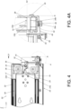
FIG. 4 is a diagram showing the second rail located at the retracted position relative to the first rail of the slide rail assembly with the handle in the second state configured to unlock the second rail from the first rail according to the first embodiment of the present invention; -
FIG. 4A is an enlarged view of an area A ofFIG. 4 ; -
FIG. 5 is a diagram showing the second rail being moved to an extended position along an opening direction relative to the first rail of the slide rail assembly with the handle in the second state according to the first embodiment of the present invention; -
FIG. 5A is an enlarged view of an area A ofFIG. 5 ; -
FIG. 6 is a diagram showing the second rail being moved from the extended position to the retracted position along a retracting direction relative to the first rail of the slide rail assembly with the handle in the second state according to the first embodiment of the present invention; -
FIG. 7 is a diagram showing the slide rail assembly being mounted to a rack according to the first embodiment of the present invention; -
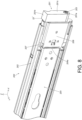
FIG. 8 is a diagram showing a slide rail assembly with a handle in a first state according to a second embodiment of the present invention; -
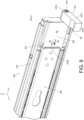
FIG. 9 is a diagram showing the slide rail assembly with the handle in a second state according to the second embodiment of the present invention; -
FIG. 10 is a diagram showing the handle according to the second embodiment of the present invention; -
FIG. 11 is a diagram showing a second rail located at a retracted position relative to a first rail of the slide rail assembly with the handle in the first state according to the second embodiment of the present invention; -
FIG. 12 is a diagram showing the second rail located at the retracted position relative to the first rail of the slide rail assembly with the handle in the second state configured to unlock the second rail from the first rail according to the second embodiment of the present invention; -
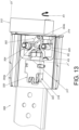
FIG. 13 is a diagram showing a second rail of a slide rail assembly further arranged with a working member, a locking member in a locking state and an elastic feature configured to work with the working member according to a third embodiment of the present invention; -
FIG. 14 is a diagram showing the second rail located at a retracted position relative to a first rail of the slide rail assembly with the locking member in the locking state according to the second embodiment of the present invention; and -
FIG. 15 is a diagram showing the locking member on the second rail of the slide rail assembly being in an unlocking state according to the third embodiment of the present invention. - As shown in
FIG. 1 andFIG. 2 , aslide rail assembly 20 comprises afirst rail 22, asecond rail 24 and ahandle 26 according to a first embodiment of the present invention. Preferably, theslide rail assembly 20 further comprises athird rail 28 movably mounted between thefirst rail 22 and thesecond rail 24. InFIG. 1 andFIG. 2 , thesecond rail 24 is located at a retracted position R relative to thefirst rail 22. Thesecond rail 24 is longitudinally movable relative to thefirst rail 22. In the figures, the X axis is a longitudinal direction (or a length direction or a moving direction of the slide rail), the Y axis is a transverse direction (or a lateral direction of the slide rail), and the Z axis is a vertical direction (or a height direction of the slide rail). - The
handle 26 is movable relative to thesecond rail 24. More particularly, thehandle 26 is pivoted to thesecond rail 24 through ashaft member 30, such that thehandle 26 is movable to switch between a first state S1 (as shown inFIG. 1 ) and a second state S2 (as shown inFIG. 2 ). Theshaft member 30 is arranged in a direction substantially identical to a moving direction of thesecond rail 24 relative to thefirst rail 22. In other words, theshaft member 30 is arranged in a direction substantially identical to a length direction of the second rail 24 (or the longitudinal direction or the X axis direction). Furthermore, when thehandle 26 is in the second state S2, a user can apply a force F to thehandle 26 along an opening direction D1 (for example, the user can easily hold thehandle 26 in the second state S2 to apply the force F as shown inFIG. 2 ), such that thesecond rail 24 can be easily pulled out relative to thefirst rail 22 along the opening direction D1. - Preferably, when the
handle 26 is in the first state S1 (as shown inFIG. 1 ), thehandle 26 is arranged in a direction substantially identical to a height direction of the second rail 24 (or the Z axis direction). - Preferably, when the
handle 26 is in the second state S2 (as shown inFIG. 2 ), thehandle 26 is arranged in a direction substantially identical to a transverse direction of the second rail 24 (or the Y axis direction). - Preferably, the moving direction of the
second rail 24 relative to thefirst rail 22, the height direction of thesecond rail 24 and the transverse direction of thesecond rail 24 are perpendicular to each other. - Preferably, the
second rail 24 has an outer side L1 and an inner side L2 opposite to each other. The outer side L1 is adjacent to and faces toward the first rail 22 (or the third rail 28). Furthermore, thefirst rail 22 has afirst end part 22a and asecond end part 22b opposite to each other, such as a front end part and a rear end part. Similarly, thesecond rail 24 has afirst end part 24a and asecond end part 24b opposite to each other, such as a front end part and a rear end part. - As shown in
FIG. 3 andFIG. 4 , thefirst rail 22 is arranged with abracket 25. Thebracket 25 is connected (such as fixedly connected) to thefirst rail 22 to be seen as a part of thefirst rail 22. Preferably, thefirst rail 22 comprises a blockingpart 19. The blockingpart 19 is arranged on one of thefirst rail 22 and thebracket 25. In the present embodiment, the blockingpart 19 is arranged on anextension component 17 of thebracket 25, and the blockingpart 19 is adjacent to thefirst end part 22a of thefirst rail 22. - The
handle 26 is rotatable to switch between the first state S1 (as shown inFIG. 3 ) and the second state S2 (as shown inFIG. 4 ) through theshaft member 30. Thehandle 26 comprises afirst end 26a, asecond end 26b and anoperating section 26c connected between thefirst end 26a and thesecond end 26b (as shown inFIG. 3 and FIG. 3A ). Theshaft member 30 is adjacent to thefirst end 26a of thehandle 26. Thehandle 26 is pivoted to a connectingcomponent 32 on thesecond rail 24 through theshaft member 30. The connectingcomponent 32 is connected (such as fixedly connected) to thesecond rail 24 to be seen as a part of thesecond rail 24. When thehandle 26 is in the second state S2, theoperating section 26c of thehandle 26 is configured to be held by the user to pull out thesecond rail 24 from the retracted position R along the opening direction D1 relative to the first rail 22 (please also refer toFIG. 4 andFIG. 2 ). - Preferably, the
slide rail assembly 20 further comprises an elastic member 33 (as shown inFIG. 3A ) . Thehandle 26 is configured to be held at the first state S1 in response to an elastic force of theelastic member 33. Theelastic member 33 can be a torsion spring, or other object with elasticity, but the present invention is not limited thereto. Theelastic member 33 comprise a firstelastic section 33a, a secondelastic section 33b (as shown inFIG. 4A ) and amiddle section 33c (as shown inFIG. 3A ) connected between the firstelastic section 33a and the secondelastic section 33b. Themiddle section 33c is arranged on a main body of theshaft member 30. The firstelastic section 33a is configured to abut against thehandle 26, and the secondelastic section 33b is configured to abut against the connectingcomponent 32 on thesecond rail 24; or the secondelastic section 33b is configured to abut against thehandle 26, and the firstelastic section 33a is configured to abut against the connectingcomponent 32 on thesecond rail 24. - Preferably, the
slide rail assembly 20 further comprises a lockingmember 34 movably mounted on thesecond rail 24. In the present embodiment, the lockingmember 34 is pivoted to the connectingcomponent 32 on thesecond rail 24 through anauxiliary shaft 36. In other words, the lockingmember 34 is pivoted to thesecond rail 24. Theauxiliary shaft 36 is arranged in a direction substantially identical to the transverse direction of the second rail 24 (or the Y axis direction). When thesecond rail 24 is located at the retracted position R relative to thefirst rail 22, a lockingpart 38 of the lockingmember 34 is configured to be blocked by the blockingpart 19 in order to prevent thesecond rail 24 from being moved away from the retracted position R relative to the first rail 22 (as shown inFIG. 3 ). - Preferably, the
handle 26 comprises a supportingfeature 40. The supportingfeature 40 has a guiding part (such as an inclined surface or an arc surface). When thesecond rail 24 is located at the retracted position R relative to thefirst rail 22 and when thehandle 26 is in the first state S1, thehandle 26 is configured to support the lockingmember 34 through the supportingfeature 40, in order to hold the lockingmember 38 to be blocked by the blocking part 19 (as shown inFIG. 3 ). - Preferably, the
handle 26 further comprises a guidingfeature 42. The guidingfeature 42 has an inclined surface or an arc surface. The guidingfeature 42 and the supportingfeature 40 together define a predetermined space K configured to accommodate anextension part 44 of the lockingmember 34, such that theextension part 44 can be supported by the supportingfeature 40 of thehandle 26. Theauxiliary shaft 36 is located between the lockingpart 38 and the extension part 44 (as shown inFIG. 3 ). - Preferably, during a process of moving the
handle 26 to switch from the first state S1 (as shown inFIG. 3 and FIG. 3A ) to the second state S2 (as shown inFIG. 4 and FIG. 4A ), thehandle 26 is configured to move theextension part 44 of the lockingmember 34 through the guiding feature 42 (as shown inFIG. 3 and FIG. 3A ), in order to drive the lockingmember 34 to rotate a predetermined angle. Moreover, the supportingfeature 40 of thehandle 26 no longer supports theextension part 44 of the lockingmember 34, such that the lockingpart 38 of the lockingmember 34 is no longer blocked by the blockingpart 19, in order to allow thesecond rail 24 to be moved away from the retracted position R along the opening direction D1 relative to the first rail 22 (as shown inFIG. 4 and FIG. 4A ). - Preferably, the
first rail 22 is arranged with anauxiliary structure 46. In the present embodiment, theauxiliary structure 46 is arranged on thebracket 25 of thefirst rail 22, and theauxiliary structure 46 is a pin, but the present invention is not limited thereto. Theauxiliary structure 46 is laterally (transversely) protruded relative to thefirst rail 22. Thesecond rail 24 is arranged with an auxiliaryelastic member 48. The auxiliaryelastic member 48 is arranged with a firstpredetermined feature 50, and thehandle 26 is arranged with a secondpredetermined feature 52. The firstpredetermined feature 50 and the secondpredetermined feature 52 are a combination of a protruded part and a recessed part (or a structure formed with a space or a hole) . In the present embodiment, the firstpredetermined feature 50 is a fixing bolt with an extension protrudedpart 50a, and the secondpredetermined feature 52 is a structure formed with a hole, but the present invention is not limited thereto. In addition, the auxiliaryelastic member 48 is connected to the connectingcomponent 32 on thesecond rail 24 in the present embodiment. - When the
second rail 24 is located at the retracted position R relative to thefirst rail 22 and when thehandle 26 is in the second state S2 (as shown inFIG. 4 and FIG. 4A ), theauxiliary structure 46 and the auxiliaryelastic member 48 abut against each other, such that the auxiliaryelastic member 48 is configured to accumulate an auxiliary elastic force f, and the first predetermined feature 50 (the extension protrudedpart 50a of the fixing bolt) is not engaged with the second predetermined feature 52 (the hole of the structure) as shown inFIG. 4 and FIG. 4A . - As shown in
FIG. 4 andFIG. 5 , when thesecond rail 24 is moved a predetermined distance from the retracted position R (as shown inFIG. 4 and FIG. 4A ) to an extended position E along the opening direction D1 relative to the first rail 22 (as shown inFIG. 5 and FIG. 5A ), theauxiliary structure 46 and the auxiliaryelastic member 48 no longer abut against each other, such that the firstpredetermined feature 50 is engaged with the secondpredetermined feature 52 in response to the auxiliary elastic force f being released by the auxiliaryelastic member 48. For example, the first predetermined feature 50 (the extension protrudedpart 50a of the fixing bolt) is inserted into the second predetermined feature 52 (the hole of the structure) in order to hold thehandle 26 in the second state S2 (as shown inFIG. 5 and FIG. 5A ). In other words, theelastic member 33 is configured to be held in a state of accumulating an elastic force through mutually engaging the firstpredetermined feature 50 with the secondpredetermined feature 52. - As shown in
FIG. 5 andFIG. 6 , one end of the auxiliaryelastic member 48 is arranged with a guiding section 54 (such as an inclined surface or an arc surface). During a process of thesecond rail 24 being moved from the extended position E (as shown inFIG. 5 and FIG. 5A ) to the retracted position R along a retracting direction D2 relative to the first rail 22 (as shown inFIG. 6 ), the auxiliaryelastic member 48 is configured to abut against theauxiliary structure 46 on thefirst rail 22 through the guiding section 54 (please refer toFIG. 6 ), so as to drive the firstpredetermined feature 50 to move to disengage the first predetermined feature 50 (the extension protrudedpart 50a of the fixing bolt) from the second predetermined feature 52 (as shown inFIG. 4 and FIG. 4A ), in order to allow thehandle 26 to return to the first state S1 (as shown inFIG. 3 and FIG. 3A ) from the second state S2 (as shown inFIG. 4 and FIG. 4A ). Preferably, thehandle 26 is driven to move to switch from the second state S2 to the first state S1 in response to the elastic force being released by theelastic member 33. During a process of thehandle 26 returning to the first state S1 from the second state S2, the supportingfeature 40 of thehandle 26 is configured to contact theextension part 44 of the lockingmember 34 through the guiding part (such as an inclined surface or an arc surface), so as to drive the lockingmember 34 to move back to the state being blocked by the blockingpart 19. As such, thesecond rail 24 is locked at the retracted position R relative to thefirst rail 22 again (as shown inFIG. 3 and FIG. 3A ). - In addition, when the
second rail 24 is moved back to the retracted position R relative to the first rail 22 (as shown inFIG. 3 and FIG. 3A ), theauxiliary structure 46 and the auxiliaryelastic member 48 abut against each other again, such that the auxiliaryelastic member 48 accumulates the auxiliary elastic force f again. - AS shown in
FIG. 7 , theslide rail assembly 20 is mounted to a rack 56 (or a cabinet). For example, thefirst rail 22 is configured to be mounted to at least one post of therack 56 through thebracket 25, and thesecond rail 24 is configured to carry a carried object (not shown). However, for different structural design or specific requirement, some part of the rack 56 (such as a wall part 58) may block at an outer side of theslide rail assembly 20. Therefore, thehandle 26 provided in the present embodiment is configured to be moved toward an inner side of the slide rail assembly 20 (such as toward the inner side L2 of the second rail 24) by the user to switch from the first state S1 to the second state S2, such that thesecond rail 24 can be easily pulled out along the opening direction D1 relative to thefirst rail 22 without being affected by thewall part 58. - Furthermore, when the
handle 26 is in the second state S2, theoperating section 26c of thehandle 26 is extended beyond the inner side L2 of thesecond rail 24 by a predetermined distance M, and the user can hold theoperating section 26c of thehandle 26 with his hand to apply a force F along the opening direction D1, so as to easily and conveniently pull out thesecond rail 24 from the retracted position R along the opening direction D1 relative to thefirst rail 22. -
FIG. 8 to FIG. 12 show aslide rail assembly 200 according to a second embodiment of the present invention. The difference between theslide rail assembly 200 of the second embodiment and theslide rail assembly 20 of the first embodiment substantially lies in structural design of thehandle 201. - As shown in
FIG. 8 to FIG. 10 , thehandle 201 comprises afirst end 201a, asecond end 201b and anoperating section 201c connected between thefirst end 201a and thesecond end 201b (as shown inFIG. 8 andFIG. 9 ). Similar to the first embodiment, thehandle 201 is pivoted to asecond rail 204 through ashaft member 203, such that thehandle 201 is movable to switch between a first state S1' (as shown inFIG. 8 ) and a second state S2' (as shown inFIG. 9 ). Thehandle 201 is arranged with a drivingpart 206, such as a protrusion (as shown inFIG. 10 ) . Similar to the first embodiment, afirst end 204a of thesecond rail 204 is arranged with a connecting component 207 (as shown inFIG. 8 orFIG. 9 ), and thehandle 201 is pivotally connected to the connectingcomponent 207 on thesecond rail 204 through theshaft member 203. The connectingcomponent 207 is connected (such as fixedly connected) to thesecond rail 204 to be seen as a part of thesecond rail 204. The connectingcomponent 207 comprises acasing 208, and thecasing 208 accommodates a locking member 210 (as shown inFIG. 11 ). - As shown in
FIG. 11 and FIG. 12 , the lockingmember 210 is movably mounted on thesecond rail 204. In the present embodiment, the lockingmember 210 is pivoted to the connectingcomponent 207 of thesecond rail 204 through anauxiliary shaft 212. Different from the first embodiment, theauxiliary shaft 212 of the second embodiment is arranged in a direction substantially identical to a height direction of the second rail 204 (or the aforementioned Z-axis direction). - Preferably, the
slide rail assembly 200 further comprises anelastic member 214 configured to provide an elastic force to the lockingmember 210. For example, theelastic member 214 can be an elastic piece, or other type of component with elasticity. Configuration and structure of theelastic member 214 is not limited. Theelastic member 214 comprises anelastic part 215 configured to provide the elastic force to the lockingmember 210, such that a lockingpart 216 of the lockingmember 210 can be held in a state of being blocked by a blocking section 219 (or a blocking wall) of a blockingpart 218 of a first rail 202 (or a bracket of the first rail 202), in order to prevent thesecond rail 204 from being moved away from the retracted position R relative to the first rail 202 (as shown inFIG. 11 ). - Preferably, the elastic force of the
elastic member 214 not only can hold the lockingpart 216 of the lockingmember 210 to be blocked by the blockingpart 218, but also can hold thehandle 201 in the first state S1' through the drivingpart 206 and the lockingmember 210 abutting against each other. In other words, thehandle 201 is configured to be held in the first state S1' in response to the elastic force of the elastic member 214 (as shown inFIG. 11 ). - Furthermore, when the
handle 201 is moved to switch from the first state S1' (as shown inFIG. 11 ) to the second state S2' (as shown inFIG. 12 ), the drivingpart 206 of thehandle 201 is configured to drive the lockingmember 210 to rotate a predetermined angle, such that the lockingpart 216 of the lockingmember 210 is no longer blocked by the blockingpart 218, in order to allow thesecond rail 204 to be moved away from the retracted position R along the opening direction D1 relative to the first rail 202 (shown inFigure 12 ). Preferably, thesecond rail 204 is formed with acorresponding hole 220. When the lockingmember 210 is rotated the predetermined angle, a portion of the lockingmember 210 is configured to be extended into thecorresponding hole 220, so as to provide space for the lockingmember 210 to move. - When the
handle 201 is in the second state S2', theoperating section 201c of thehandle 201 is extended beyond an inner side L2' of thesecond rail 204 by a predetermined distance M' (as shown inFIG. 12 ). The user can hold theoperating section 201c of thehandle 201 with his hand to apply a force along the opening direction D1, so as to easily and conveniently pull out thesecond rail 204 from the retracted position R along the opening direction D1 relative to thefirst rail 202. -
FIG. 13 to FIG. 15 show aslide rail assembly 300 according to a third embodiment of the present invention. Afirst rail 308 of theslide rail assembly 300 shown inFIG. 14 is omitted inFIG. 13 andFIG. 15 . The difference between theslide rail assembly 300 of the third embodiment and theslide rail assembly 200 of the second embodiment substantially lies in theslide rail assembly 300 further comprising a workingmember 302 and anelastic feature 304. The workingmember 302 is pivoted to asecond rail 306 through ashaft part 305, and theshaft part 305 is arranged in a direction substantially identical to a transverse direction of the second rail 306 (or the Y axis direction). Theelastic feature 304 comprises a firstelastic part 304a and a secondelastic part 304b. - When the
second rail 306 is located at the retracted position R relative to the first rail 308 (as shown inFIGS. 14 andFIG. 13 ), the firstelastic part 304a of theelastic feature 304 is configured to contact a predetermined structure 310 (such as a structure having an inclined surface or an arc surface shown inFIG. 14 ) of thefirst rail 308, and the secondelastic part 304b of theelastic feature 304 is configured to contact the working member 302 (as shown inFIG. 13 ), such that theelastic feature 304 is configured to provide an elastic force to ahandle 312 through the workingmember 302 and a portion of the handle 312 (such as a driving part 314) to hold thehandle 312 in the first state S1' (as shown inFIG. 13 andFIG. 14 ). - During a process of the
handle 312 being rotated along a first rotating direction R1 to switch from the first state S1' (as shown inFIG. 13 ) to the second state S2' (as shown inFIG. 15 ), thehandle 312 is configured to drive a lockingmember 316 to rotate along a third rotating direction R3 to switch from a locking state J1' (as shown inFIG. 13 andFIG. 14 ) to an unlocking state J2' (as shown inFIG. 15 ) through the drivingpart 314 driving the workingmember 302 to rotate along a second rotating direction R2, such that a lockingpart 317 of the lockingmember 316 is no longer blocked by a blockingpart 318 of thefirst rail 308, in order to allow thesecond rail 306 to be moved away from the retracted position R along the opening direction D1 relative to the first rail 308 (as shown inFIG. 14 ) . Moreover, when thesecond rail 306 is moved away from the retracted position R along the opening direction D1 relative to the first rail 308 (or located at an extended position), the firstelastic part 304a of theelastic feature 304 no longer contacts thepredetermined structure 310 of thefirst rail 308, such that theelastic feature 304 no longer provides the elastic force to thehandle 312 through the workingmember 302 and the drivingpart 314 of thehandle 312, so as to allow thehandle 312 to stay in the second state S2', and allow the lockingmember 316 to stay in the unlocking state J2' (as shown inFIG. 15 ). - When the
second rail 306 is moved to return to the retracted position R from the extended position relative to thefirst rail 308 along a retracting direction D2, the firstelastic part 304a of theelastic feature 304 contacts thepredetermined structure 310 of thefirst rail 308 again (as shown inFIG. 14 ), such that theelastic feature 304 is configured to provide the elastic force to thehandle 312 through the workingmember 302 and the drivingpart 314 of the handle 312 (as shown inFIG. 13 ), in order to drive thehandle 312 to move to switch from the second state S2' (as shown inFIG. 15 ) to the first state S1'. Moreover, the lockingmember 316 is correspondingly moved back to the locking state J1' in response to an elastic force provided by anelastic part 322 of anelastic member 320. - Therefore, the slide rail assembly according to the embodiments of the present invention has the following technical features:
- 1. The handle (26, 201, 312) is pivoted to the second rail (24, 204, 306) through a shaft member (30, 203), such that the handle (26, 201, 312) is movable to switch between the first state (S1, S1') and the second state (S2, S2'). The shaft member (30, 203) is arranged in a direction substantially identical to a moving direction (or the longitudinal direction) of the second rail (24, 204, 306) relative to the first rail (22, 202, 308), such that the handle (26, 201, 312) can be moved toward the inner side of the slide rail assembly (20, 200, 300) by the user to switch from the first state (S1, S1') to the second state (S2, S2'), so as to allow the user to easily and conveniently pull out the second rail (24, 204, 306) from the retracted position R along the opening direction D1 relative to the first rail (22, 202, 308).
- 2. When the handle (26, 201, 312) is in the second state (S2, S2'), the operating section (26c, 201c) of the handle (26, 201, 312) is extended beyond the inner side (L2, L2') of the second rail (24, 204, 306) by a predetermined distance (M, M'), and the user can hold the operating section (26c, 201c) of the handle (26, 201, 312) with his hand to apply a force along the opening direction D1, so as to easily and conveniently pull out the second rail (24, 204, 306) from the retracted position R along the opening direction D1 relative to the first rail (22, 202, 308).
- 3. The second rail (24, 204, 306) located at the retracted positionR relative to the first rail (22, 202, 308) can be unlocked from the first rail (22, 202, 308) through operating the handle (26, 201, 312).
- 4. In the first embodiment, the
first rail 22 is arranged with theauxiliary structure 46, thesecond rail 24 is arranged with the auxiliaryelastic member 48, the auxiliaryelastic member 48 is arranged with the firstpredetermined feature 50, and thehandle 26 is arranged with the secondpredetermined feature 52. When thesecond rail 24 is located at the retracted position R relative to thefirst rail 22 and when thehandle 26 is in the second state S2, theauxiliary structure 46 is configured to abut against the auxiliaryelastic member 48, such that the auxiliaryelastic member 48 accumulates the auxiliary elastic force, and the firstpredetermined feature 50 is prevented from engaging with the secondpredetermined feature 52. When thesecond rail 24 is moved a predetermined distance from the retracted position R along the opening direction D1 relative to the first rail 22 (such as being moved to the extended position E), theauxiliary structure 46 no longer abuts against the auxiliaryelastic member 48, such that the auxiliaryelastic member 48 releases the auxiliary elastic force to drive the firstpredetermined feature 50 to engage with the secondpredetermined feature 52, in order to hold thehandle 26 in the second state S2. During the process of thesecond rail 24 being moved from the extended position E to the retracted position R along the retracting direction D2 relative to thefirst rail 22, the auxiliaryelastic member 48 is driven by theauxiliary structure 46 to disengage the firstpredetermined feature 50 from the secondpredetermined feature 52, in order to allow thehandle 26 to switch from the second state S2 back to the first state S1. Preferably, thehandle 26 returns to the first state S1 from the second state S2 in response to the elastic force of theelastic member 33. - 5. In the first embodiment, the elastic force of the
elastic member 33 can be directly applied to thehandle 26, such that thehandle 26 is held in the first state S1 in response to the elastic force of theelastic member 33. Or in the second embodiment, the elastic force of theelastic member 214 can be indirectly applied to thehandle 201 through the lockingmember 210 to hold thehandle 201 in the first state S1'.
Claims (14)
- A slide rail assembly (20, 200, 300), comprising:a first rail (22, 202, 308);a second rail (24, 204, 306) movable relative to the first rail (22, 202, 308); anda handle (26, 201, 312) pivoted to the second rail (24, 204, 306) through a shaft member (30, 203) and movable relative to the second rail (24, 204, 306) to switch between a first state and a second state;characterized in that:
wherein the shaft member (30, 203) is arranged in a direction substantially identical to a moving direction of the second rail (24, 204, 306) relative to the first rail (22, 202, 308). - The slide rail assembly of claim 1, characterized in that when the handle (26, 201, 312) is in the first state, the handle (26, 201, 312) is arranged in a direction substantially identical to a height direction of the second rail (24, 204, 306).
- The slide rail assembly of claim 2, characterized in that when the handle (26, 201, 312) is in the second state, the handle (26, 201, 312) is arranged in a direction substantially identical to a transverse direction of the second rail (24, 204, 306).
- The slide rail assembly of claim 3, characterized in that the moving direction of the second rail (24, 204, 306), the height direction of the second rail (24, 204, 306) and the transverse direction of the second rail (24, 204, 306) are perpendicular to each other.
- The slide rail assembly of any of claims 1-4, characterized in that the second rail (24, 204, 306) has an outer side and an inner side opposite to each other, the outer side is adjacent to and faces toward the first rail (22, 202, 308); the handle (26, 201, 312) has a first end, a second end and an operating section connected between the first end and the second end; wherein when the handle (26, 201, 312) is in the second state, the operating section of the handle (26, 201, 312) is configured to be held by a user to pull out the second rail (24, 204, 306) from a retracted position along an opening direction relative to the first rail (22, 202, 308).
- The slide rail assembly of claim 5, characterized in that the first rail comprises a blocking part (19, 218, 318), and the slide rail assembly (20, 200, 300) further comprises a locking member (34, 210, 316) movably mounted on the second rail (24, 204, 306) ; wherein when the second rail (24, 204, 306) is located at the retracted position relative to the first rail (22, 202, 308), the locking member (34, 210, 316) is configured to be blocked by the blocking part (19, 218, 318) in order to prevent the second rail (24, 204, 306) from being moved away from the retracted position.
- The slide rail assembly of claim 6, characterized in that the handle (26) has a supporting feature (40) ; wherein when the second rail (24) is located at the retracted position relative to the first rail (22) and when the handle (26) is in the first state, the supporting feature (40) of the handle (26) is configured to support the locking member (34); during a process of the handle (26) being moved to switch from the first state to the second state, the supporting feature (40) of the handle (26) no longer supports the locking member (34), such that the locking member (34) is no longer blocked by the blocking part (19).
- The slide rail assembly of claim 7, characterized in that the first rail (22) is arranged with an auxiliary structure (46), the second rail (24) is arranged with an auxiliary elastic member (48), the auxiliary elastic member (48) is arranged with a first predetermined feature (50), and the handle (26) is arranged with a second predetermined feature (52); wherein when the second rail (24) is located at the retracted position relative to the first rail (22) and when the handle (26) is in the second state, the auxiliary structure (46) is configured to abut against the auxiliary elastic member (48), such that the auxiliary elastic member (48) accumulates an auxiliary elastic force, and the first predetermined feature (50) is prevented from engaging with the second predetermined feature (52).
- The slide rail assembly of claim 8, characterized in that when the second rail (24) is moved a predetermined distance from the retracted position along the opening direction relative to the first rail (22), the auxiliary structure (46) no longer abuts against the auxiliary elastic member (48), such that the auxiliary elastic member (48) releases the auxiliary elastic force to drive the first predetermined feature (50) to engage with the second predetermined feature (52), in order to hold the handle (26) in the second state.
- The slide rail assembly of claim 9, characterized in that during a process of the second rail (24) being moved from an extended position to the retracted position along a retracting direction relative to the first rail (22), the auxiliary elastic member (48) is driven by the auxiliary structure (46) to disengage the first predetermined feature (50) from the second predetermined feature (52), in order to allow the handle (26) to switch from the second state to the first state.
- The slide rail assembly of claim 10, further characterized by an elastic member (33); wherein when the first predetermined feature (50) is disengaged from the second predetermined feature (52), the elastic member (33) is configured to provide an elastic force to drive the handle (26) to switch from the second state to the first state.
- The slide rail assembly of claim 6, characterized in that during a process of the handle (201, 312) being moved to switch from the first state to the second state, the handle (201, 312) is configured to drive the locking member (210, 316) to move through a driving part (206, 314), such that the locking member (210, 316) is no longer blocked by the blocking part (216, 317) .
- The slide rail assembly of claim 6, further characterized by a working member (302) and an elastic feature (304); wherein the working member (302) is movable relative to the second rail (306), and the elastic feature (304) comprises a first elastic part and a second elastic part; wherein when the second rail (306) is located at the retracted position relative to the first rail (308), the first elastic part is configured to contact a predetermined structure (310) of the first rail (308), and the second elastic part is configured to contact the working member (302), such that the elastic feature (304) is configured to provide an elastic force to the handle (312) through the working member (302) to hold the handle (312) in the first state; wherein during a process of the handle (312) being moved to switch from the first state to the second state, the handle (312) is configured to drive the locking member (316) to move through the working member (302), such that the locking member (316) is no longer blocked by the blocking part (317), in order to allow the second rail (306) to be moved away from the retracted position along the opening direction relative to the first rail (308); wherein when the second rail (306) is moved away from the retracted position along the opening direction relative to the first rail (308), the first elastic part no longer contacts the predetermined structure (310) of the first rail (308), such that the elastic feature (304) no longer provides the elastic force to the handle (312) through the working member (302), so as to allow the handle (312) to stay in the second state; wherein when the second rail (306) is moved to return to the retracted position from an extended position relative to the first rail (308), the elastic feature (304) is configured to provide the elastic force to the handle (312) through the working member (302), in order to drive the handle (312) to move to switch from the second state to the first state.
- The slide rail assembly of claim 5, characterized in that when the handle (26, 201, 312) is in the second state, the operating section of the handle (26, 201, 312) is extended beyond the inner side of the second rail (24, 204, 306) by a predetermined distance.
Applications Claiming Priority (1)
| Application Number | Priority Date | Filing Date | Title |
|---|---|---|---|
| TW112143584A TWI847910B (en) | 2023-11-09 | 2023-11-09 | Slide rail assembly |
Publications (1)
| Publication Number | Publication Date |
|---|---|
| EP4552532A1 true EP4552532A1 (en) | 2025-05-14 |
Family
ID=91027104
Family Applications (1)
| Application Number | Title | Priority Date | Filing Date |
|---|---|---|---|
| EP24174320.2A Pending EP4552532A1 (en) | 2023-11-09 | 2024-05-06 | Slide rail assembly |
Country Status (4)
| Country | Link |
|---|---|
| US (1) | US12604981B2 (en) |
| EP (1) | EP4552532A1 (en) |
| JP (1) | JP7793874B2 (en) |
| TW (1) | TWI847910B (en) |
Families Citing this family (1)
| Publication number | Priority date | Publication date | Assignee | Title |
|---|---|---|---|---|
| TWI908460B (en) * | 2024-11-12 | 2025-12-11 | 川湖科技股份有限公司 | Slide rail mechanism |
Citations (4)
| Publication number | Priority date | Publication date | Assignee | Title |
|---|---|---|---|---|
| US639A (en) | 1838-03-17 | of boston | ||
| US10631A (en) | 1854-03-14 | Machine fob making shovel-handles | ||
| US20120076446A1 (en) * | 2010-09-24 | 2012-03-29 | King Slide Works Co., Ltd. | Latch and release device for slide assembly |
| CA2687402C (en) * | 2007-05-07 | 2014-10-28 | Paul Hettich Gmbh & Co. Kg | Guiding rail for a cabinet pull-out part |
Family Cites Families (26)
| Publication number | Priority date | Publication date | Assignee | Title |
|---|---|---|---|---|
| USRE28344E (en) * | 1968-11-05 | 1975-02-25 | Slidu assembly | |
| US6560114B2 (en) * | 2001-06-29 | 2003-05-06 | Intel Corporation | Rack-mounted server and associated methods |
| US6883884B2 (en) * | 2002-09-25 | 2005-04-26 | King Slide Works Co., Ltd. | Latch assembly for a track device |
| US8317278B2 (en) * | 2010-08-18 | 2012-11-27 | Knape & Vogt Manufacturing Company | Releasably locking slide assemblies |
| TW201221087A (en) * | 2010-11-30 | 2012-06-01 | Hon Hai Prec Ind Co Ltd | Mounting apparatus for slide rail |
| US8282176B1 (en) * | 2011-06-10 | 2012-10-09 | King Slide Works Co., Ltd. | Slide assembly having locking mechanism |
| US9723745B2 (en) * | 2015-02-16 | 2017-08-01 | Cisco Technology, Inc. | Line card ejector with line card removal indication |
| TWI544862B (en) * | 2015-10-16 | 2016-08-01 | King Slide Works Co Ltd | Support assembly and support device thereof |
| TWI587814B (en) * | 2015-12-03 | 2017-06-21 | 川湖科技股份有限公司 | Slide rail assembly and locking device thereof |
| TWI568381B (en) * | 2015-12-21 | 2017-02-01 | 川湖科技股份有限公司 | Slide rail assembly and guiding mechanism thereof |
| TWI604775B (en) * | 2016-10-24 | 2017-11-01 | 緯創資通股份有限公司 | Handle locking device and electronic system case having the same |
| CN206640916U (en) * | 2017-02-09 | 2017-11-14 | 索斯科公司 | Computer rack system and frame attachment arrangement |
| TWI615114B (en) * | 2017-03-27 | 2018-02-21 | 川湖科技股份有限公司 | Bracket for slide rail |
| US10264698B2 (en) * | 2017-08-25 | 2019-04-16 | Facebook, Inc. | Systems and methods for mounting assembly pull-handles |
| TWI659712B (en) * | 2018-04-02 | 2019-05-21 | 川湖科技股份有限公司 | Slide rail assembly |
| TWI689238B (en) * | 2019-02-01 | 2020-03-21 | 勤誠興業股份有限公司 | Server device and its latch mechanism |
| TWI702020B (en) * | 2019-06-12 | 2020-08-21 | 川湖科技股份有限公司 | Slide rail assembly |
| US11197389B2 (en) * | 2020-04-06 | 2021-12-07 | Super Micro Computer Inc. | Server chassis |
| US11382233B2 (en) * | 2020-10-30 | 2022-07-05 | Quanta Computer Inc. | Removable lever for inserting and removing a tray from a chassis module of a server rack |
| TWI733625B (en) * | 2020-11-24 | 2021-07-11 | 川湖科技股份有限公司 | Slide rail assembly |
| TWI817122B (en) * | 2021-05-14 | 2023-10-01 | 緯穎科技服務股份有限公司 | Handle module, server and server system |
| TWI856449B (en) * | 2022-12-09 | 2024-09-21 | 川湖科技股份有限公司 | Slide rail mechanism and slide rail assembly thereof |
| TWI861632B (en) * | 2022-12-13 | 2024-11-11 | 川湖科技股份有限公司 | Slide rail assembly |
| TWI829509B (en) * | 2023-01-13 | 2024-01-11 | 川湖科技股份有限公司 | Slide rail assembly |
| TWI842561B (en) * | 2023-06-08 | 2024-05-11 | 川湖科技股份有限公司 | Slide rail assembly |
| TWI847902B (en) * | 2023-10-30 | 2024-07-01 | 川湖科技股份有限公司 | Slide rail assembly |
-
2023
- 2023-11-09 TW TW112143584A patent/TWI847910B/en active
-
2024
- 2024-02-27 US US18/588,529 patent/US12604981B2/en active Active
- 2024-05-06 EP EP24174320.2A patent/EP4552532A1/en active Pending
- 2024-06-04 JP JP2024090341A patent/JP7793874B2/en active Active
Patent Citations (4)
| Publication number | Priority date | Publication date | Assignee | Title |
|---|---|---|---|---|
| US639A (en) | 1838-03-17 | of boston | ||
| US10631A (en) | 1854-03-14 | Machine fob making shovel-handles | ||
| CA2687402C (en) * | 2007-05-07 | 2014-10-28 | Paul Hettich Gmbh & Co. Kg | Guiding rail for a cabinet pull-out part |
| US20120076446A1 (en) * | 2010-09-24 | 2012-03-29 | King Slide Works Co., Ltd. | Latch and release device for slide assembly |
Also Published As
| Publication number | Publication date |
|---|---|
| JP2025079292A (en) | 2025-05-21 |
| JP7793874B2 (en) | 2026-01-06 |
| TWI847910B (en) | 2024-07-01 |
| TW202519144A (en) | 2025-05-16 |
| US20250151898A1 (en) | 2025-05-15 |
| US12604981B2 (en) | 2026-04-21 |
Similar Documents
| Publication | Publication Date | Title |
|---|---|---|
| EP3815575B1 (en) | Slide rail assembly | |
| EP4018883B1 (en) | Slide rail assembly | |
| US11540630B2 (en) | Slide rail assembly | |
| EP3679833B1 (en) | Slide rail assembly | |
| EP4035568B1 (en) | Slide rail assembly | |
| EP3886546B1 (en) | Slide rail assembly | |
| EP3750446B1 (en) | Slide rail assembly | |
| JP6994078B2 (en) | Slide rail assembly | |
| EP4164347B1 (en) | Slide rail assembly | |
| EP3960030B1 (en) | Slide rail assembly and slide rail kit thereof | |
| EP4537705B1 (en) | Slide rail assembly | |
| EP4381999A1 (en) | Slide rail mechanism and slide rail assembly thereof | |
| EP4023108B1 (en) | Slide rail assembly | |
| EP4548808B1 (en) | Slide rail assembly | |
| US12604981B2 (en) | Slide rail assembly | |
| EP4501174B1 (en) | Slide rail assembly | |
| EP4659626A1 (en) | Slide rail assembly | |
| US20250176714A1 (en) | Slide rail assembly | |
| CN120018435A (en) | Slide rail assembly | |
| CN112754197B (en) | Slide rail assembly | |
| EP4656096A1 (en) | Slide rail assembly | |
| EP4454514B1 (en) | Slide rail assembly | |
| EP4563039B1 (en) | Slide rail assembly | |
| CN113455843A (en) | Sliding rail assembly | |
| CN110557916B (en) | Bracket device for rack system and slide rail assembly |
Legal Events
| Date | Code | Title | Description |
|---|---|---|---|
| PUAI | Public reference made under article 153(3) epc to a published international application that has entered the european phase |
Free format text: ORIGINAL CODE: 0009012 |
|
| STAA | Information on the status of an ep patent application or granted ep patent |
Free format text: STATUS: REQUEST FOR EXAMINATION WAS MADE |
|
| 17P | Request for examination filed |
Effective date: 20241128 |
|
| AK | Designated contracting states |
Kind code of ref document: A1 Designated state(s): AL AT BE BG CH CY CZ DE DK EE ES FI FR GB GR HR HU IE IS IT LI LT LU LV MC ME MK MT NL NO PL PT RO RS SE SI SK SM TR |