EP4552531A1 - Slide rail assembly - Google Patents
Slide rail assembly Download PDFInfo
- Publication number
- EP4552531A1 EP4552531A1 EP24186229.1A EP24186229A EP4552531A1 EP 4552531 A1 EP4552531 A1 EP 4552531A1 EP 24186229 A EP24186229 A EP 24186229A EP 4552531 A1 EP4552531 A1 EP 4552531A1
- Authority
- EP
- European Patent Office
- Prior art keywords
- rail
- predetermined
- damping device
- damping
- slide rail
- Prior art date
- Legal status (The legal status is an assumption and is not a legal conclusion. Google has not performed a legal analysis and makes no representation as to the accuracy of the status listed.)
- Granted
Links
Images





Classifications
-
- A—HUMAN NECESSITIES
- A47—FURNITURE; DOMESTIC ARTICLES OR APPLIANCES; COFFEE MILLS; SPICE MILLS; SUCTION CLEANERS IN GENERAL
- A47B—TABLES; DESKS; OFFICE FURNITURE; CABINETS; DRAWERS; GENERAL DETAILS OF FURNITURE
- A47B88/00—Drawers for tables, cabinets or like furniture; Guides for drawers
- A47B88/40—Sliding drawers; Slides or guides therefor
- A47B88/49—Sliding drawers; Slides or guides therefor with double extensible guides or parts
-
- A—HUMAN NECESSITIES
- A47—FURNITURE; DOMESTIC ARTICLES OR APPLIANCES; COFFEE MILLS; SPICE MILLS; SUCTION CLEANERS IN GENERAL
- A47B—TABLES; DESKS; OFFICE FURNITURE; CABINETS; DRAWERS; GENERAL DETAILS OF FURNITURE
- A47B88/00—Drawers for tables, cabinets or like furniture; Guides for drawers
- A47B88/40—Sliding drawers; Slides or guides therefor
- A47B88/44—Sequencing or synchronisation of drawer slides or functional units
- A47B88/443—Successive movement of rails within drawer slides, i.e. at least one rail element is not moving during the movement of other elements
-
- A—HUMAN NECESSITIES
- A47—FURNITURE; DOMESTIC ARTICLES OR APPLIANCES; COFFEE MILLS; SPICE MILLS; SUCTION CLEANERS IN GENERAL
- A47B—TABLES; DESKS; OFFICE FURNITURE; CABINETS; DRAWERS; GENERAL DETAILS OF FURNITURE
- A47B88/00—Drawers for tables, cabinets or like furniture; Guides for drawers
- A47B88/40—Sliding drawers; Slides or guides therefor
- A47B88/473—Braking devices, e.g. linear or rotational dampers or friction brakes; Buffers; End stops
-
- A—HUMAN NECESSITIES
- A47—FURNITURE; DOMESTIC ARTICLES OR APPLIANCES; COFFEE MILLS; SPICE MILLS; SUCTION CLEANERS IN GENERAL
- A47B—TABLES; DESKS; OFFICE FURNITURE; CABINETS; DRAWERS; GENERAL DETAILS OF FURNITURE
- A47B88/00—Drawers for tables, cabinets or like furniture; Guides for drawers
- A47B88/70—Coupled drawers
-
- H—ELECTRICITY
- H05—ELECTRIC TECHNIQUES NOT OTHERWISE PROVIDED FOR
- H05K—PRINTED CIRCUITS; CASINGS OR CONSTRUCTIONAL DETAILS OF ELECTRIC APPARATUS; MANUFACTURE OF ASSEMBLAGES OF ELECTRICAL COMPONENTS
- H05K7/00—Constructional details common to different types of electric apparatus
- H05K7/14—Mounting supporting structure in casing or on frame or rack
- H05K7/1485—Servers; Data center rooms, e.g. 19-inch computer racks
- H05K7/1488—Cabinets therefor, e.g. chassis or racks or mechanical interfaces between blades and support structures
- H05K7/1489—Cabinets therefor, e.g. chassis or racks or mechanical interfaces between blades and support structures characterized by the mounting of blades therein, e.g. brackets, rails, trays
Definitions
- the present invention is related to a slide rail assembly.
- US patent number US 10,398,228B2 discloses a three-section slide rail assembly comprising a first rail, a second rail, a third rail and a damping device.
- the third rail (such as a middle rail) is movably mounted between the first rail (such as an outer rail) and the second rail (such as an inner rail).
- the damping device is mounted on the first rail.
- the third rail comprises a first pushing feature and a second pushing feature respectively located at two sides of the damping device. When the third rail is moved relative to the first rail along a first direction to be opened or along a second direction to be retracted, the damping device is capable of providing damping effect for two-way damping function.
- patent number US 10,781,855B2 discloses a slide rail assembly comprising a first rail (such as a middle rail), a ball bearing assembly, a second rail (such as an inner rail) and a damping device.
- the ball bearing assembly is movably mounted on the first rail.
- the ball bearing assembly comprises a ball retainer and a plurality of balls.
- the ball retainer comprises a stopping feature.
- the damping device is mounted on the first rail.
- the damping device corresponds to the stopping feature of the ball retainer is configured to provide a damping force.
- the ball retainer is configured to be driven to move by the second rail, such that the stopping feature of the ball retainer contacts the damping device.
- the slide rail assembly further comprises a third rail (such as an outer rail), and the first rail is movable relative to the third rail.
- the second rail (such as the inner rail) disclosed by patent ⁇ 855 is configured to drive the ball retainer to move to abut against the damping device for providing damping effect.
- the present invention aims at providing a slide rail assembly.
- the claimed slide rail assembly comprises a first rail, a second rail, a damping device and an auxiliary member.
- the first rail is arranged with a predetermined feature.
- the second rail is movable relative to the first rail.
- the damping device is arranged on the first rail.
- the auxiliary member is arranged on the second rail and configured to switch between a first predetermined state and a second predetermined state relative to the second rail.
- the auxiliary member in the first predetermined state is configured to abut against the damping device, such that the damping device provides damping effect to the second rail; and when the second rail is further moved relative to the first rail along the first direction, the predetermined feature is configured to abut against the auxiliary member to drive the auxiliary member to switch from the first predetermined state to the second predetermined state in order to detach the auxiliary member from the damping device, such that the damping device no longer provides damping effect to the second rail.
- a slide rail assembly 20 comprises a first rail 22, a second rail 24, a damping device 26, at least one predetermined feature 28 and an auxiliary member 30 according to an embodiment of the present invention.
- the second rail 24 is longitudinally movable relative to the first rail 22.
- the X axis is a longitudinal direction (or a length direction or a moving direction of the slide rail)
- the Y axis is a transverse direction (or a lateral direction of the slide rail)
- the Z axis is a vertical direction (or a height direction of the slide rail) .
- the slide rail assembly 20 further comprises a third rail 32, and the first rail 22 is movably mounted between the third rail 32 and the second rail 24.
- the third rail 32 is an outer rail
- the first rail 22 is a middle rail
- the second rail 24 is an inner rail, but the present invention is not limited thereto.
- the damping device 26 and the at least one predetermined feature 28 are arranged on one of the first rail 22 and the second rail 24, and the auxiliary member 30 is arranged on the other one of the first rail 22 and the second rail 24.
- the damping device 26 and the at least one predetermined feature 28 are arranged on the first rail 22, and the auxiliary member 30 is arranged on the second rail 24.
- the third rail 32 comprises a first wall 34a, a second wall 34b and a longitudinal wall 36 connected between the first wall 34a and the second wall 34b of the third rail 32.
- a passage 38 is defined by the first wall 34a, the second wall 34b and the longitudinal wall 36 of the third rail 32, and configured to accommodate the first rail 22.
- the third rail 32 has a first end part 32a and a second end part 32b (such as a front end part and a rear end part) opposite to each other.
- the first rail 22 comprises a first wall 40a, a second wall 40b and a longitudinal wall 42 connected between the first wall 40a and the second wall 40b of the first rail 22.
- a passage 44 is defined by the first wall 40a, the second wall 40b and the longitudinal wall 42 of the first rail 22, and configured to accommodate the second rail 24.
- the first rail 22 has a first end part 22a and a second end part 22b (such as a front end part and a rear end part) opposite to each other.
- the damping device 26 is arranged adjacent to the first end part 22a of the first rail 22.
- the damping device 26 comprises a first damping part 46 and a second damping part 48 movable relative to each other.
- the first damping part 46 can be a cylinder body
- the second damping part 48 can be a rod body.
- the cylinder body contains a damping medium and/or an elastic member (such as a spring), and the rod body can be extended or retracted relative to the cylinder body.
- the first damping part 46 can be a rod body
- the second damping part 48 can be a cylinder body.
- the first damping part 46 is fixed to the longitudinal wall 42 of the first rail 22 through at least one connecting base 50.
- the second damping part 48 is movable relative to the first damping part 46.
- one end of the second damping part 48 away from the first damping part 46 is arranged (fixedly connected with) an actuating member 52.
- the actuating member 52 and the second damping part 48 can be seen as one piece.
- the at least one predetermined feature 28 is a protrusion
- the slide rail assembly 20 can comprise one or more predetermined features 28.
- the slide rail assembly 20 comprises two predetermined features 28, but the present invention is not limited thereto.
- the predetermined features 28 are arranged on the longitudinal wall 42 of the first rail 22, and the predetermined features 28 are located between two ends (a first end 26a and a second end 26b, such as a front end and a rear end shown in FIG. 3 ) of the damping device 26.
- the predetermined features 28 are arranged adjacent to the second damping part 48 of the damping device 26.
- the predetermined features 28 and the second damping part 48 are located at different positions on the longitudinal wall 42 of the first rail 22 along the height direction of the slide rail.
- the first rail 22 further comprises a blocking part 54 adjacent to the first end part 22a of the first rail 22 (please also refer to FIG. 3 ).
- the blocking part 54 is (transversally or laterally) protruded relative to the longitudinal wall 42 of the first rail 22, but the present invention is not limited thereto.
- the second rail 24 has a first end part 24a and a second end part 24b (such as a front end part and a rear end part) opposite to each other.
- the slide rail assembly 20 further comprises a first working member 56 and/or a second working member 58 movably mounted on the second rail 24.
- the first working member 56 and the second working member 58 are pivoted to the second rail 24 through a first shaft member 60 and a second shaft member 62 respectively.
- the second rail 24 is arranged with an auxiliary elastic member.
- the auxiliary elastic member comprises a first elastic part 66a and a second elastic part 66b configured to provide elastic forces to the first working member 56 and the second working member 58 respectively (please also refer to FIG. 4 and FIG. 9 ).
- the second rail 24 comprises a first wall 68a, a second wall 68b and a longitudinal wall 70 connected between the first wall 68a and the second wall 68b of the second rail 24.
- the auxiliary member 30 is arranged on the longitudinal wall 70 of the second rail 24.
- the auxiliary member 30 is an elastic component, such as an elastic piece, but the present invention is not limited thereto.
- the auxiliary member 30 comprises a first connecting part 31a, a second connecting part 31b and a middle part 33 located between the first connecting part 31a and the second connecting part 31b.
- the middle part 33 is extended between the first connecting part 31a and the second connecting part 31b (please also refer to Figure 4 ).
- the first connecting portion 31a and the second connecting portion 31b are connected (such as fixed) to the longitudinal wall 70 of the second rail 24.
- the middle part 33 is transversally or laterally raised relative to the longitudinal wall 70 of the second rail 24.
- a space 35 (such as an opening, but the present invention is not limited thereto) is formed between the middle part 33 and the first connecting part 31a, and the middle part 33 is arranged with a predetermined wall 37 located at an edge of the space 35 (please also refer to FIG. 4 ).
- a first guiding section G1 is arranged between the middle part 33 and the first connecting part 31a, and a second guiding section G2 is arranged between the middle part 33 and the second connecting part 31b.
- the first guiding section G1 and the second guiding section G2 can be inclined surfaces or arc surfaces.
- the slide rail assembly 20 further comprises at least one operating member.
- the slide rail assembly 20 comprises a first operating member 72 and a second operating member 74 configured to respectively drive the first working member 56 and the second working member 58 to move.
- the first operating member 72 and the second operating member 74 are operatively connected to the first working member 56 and the second working member 58 respectively.
- the slide rail assembly 20 further comprises at least one first slide assisting device 76.
- the at least one first slide assisting device 76 comprises a plurality of first balls B1.
- the at least one first slide assisting device 76 is movably mounted in the passage 38 of the third rail 32 to improve moving smoothness between the first rail 22 and the third rail 32.
- the slide rail assembly 20 further comprises a second slide assisting device 78.
- the second slide assisting device 78 comprises a plurality of second balls B2.
- the second slide assisting device 78 is movably mounted in the passage 44 of the first rail 22 to improve moving smoothness between the second rail 24 and the first rail 22.
- the slide rail assembly 20 is in a retracted state. Furthermore, the first rail 22 is retracted relative to the third rail 32, and the second rail 24 is located at a retracted position R relative to the first rail 22.
- the auxiliary member 30 is separated from the damping device 26 along the longitudinal direction.
- the auxiliary member 30 is in a first predetermined state K1 relative to the second rail 24, and the damping device 26 is in a damping preparation state (for example, the second damping part 48 is extended relative to the first damping part 46).
- the first and second working members 56, 58 are separated from the blocking part 54 along the longitudinal direction.
- An auxiliary space M is defined between the first working member 56 and the second working member 58.
- the predetermined feature 28 has a first predetermined end and a second predetermined end opposite to each other. At least one of the first predetermined end and the second predetermined end is arranged with a guiding feature.
- the first predetermined end and the second predetermined end are arranged with a first guiding feature 29a and a second guiding feature 29b respectively, and the first guiding feature 29a and the second guiding feature 29b can be inclined surfaces or arc surfaces.
- the auxiliary member 30 is configured to drive the damping device 26.
- the auxiliary member 30 in the first predetermined state K1 is configured to abut against the damping device 26 (as shown in FIG. 6 ) to drive the damping device 26 to provide damping effect F (as shown in Figure 7 ), such as providing damping effect F to the second rail 24.
- the first rail 22 when the first rail 22 is located at an opening position J relative to the third rail 32, the first end part 22a of the first rail 22 is extended beyond the first end part 32a of the third rail 32, and the first rail 22 is configured to be locked at the opening position J relative to the third rail 32.
- Such configuration is well known to those skilled in the art, no further illustration is provided for simplicity.
- the predetermined wall 37 of the auxiliary member 30 in the first predetermined state K1 is configured to abut against the actuating member 52 (as shown in FIG. 6 ) on the second damping part 48 to retract the second damping part 48 relative to the first damping part 46, so as to drive the damping device 26 to provide the damping effect F (as shown in FIG. 7 ).
- the predetermined feature 28 (such as the first guiding feature 29a of the predetermined feature 28) is configured to abut against the auxiliary member 30 (such as the first guiding section G1 of the auxiliary member 30) in order to drive the auxiliary member 30 to switch from the first predetermined state K1 to a second predetermined state K2.
- the auxiliary member 30 is elastically deformed, such that the actuating member 52 on the second damping part 48 of the damping device 26 no longer blocks a moving path of the predetermined wall 37 of the auxiliary member 30, so as to detach the predetermined wall 37 of the auxiliary member 30 from the actuating member 52 on the second damping part 48 of the damping device 26.
- the auxiliary member 30 no longer drives the damping device 26, such that the damping device 26 no longer provides the damping effect F to the second rail 24.
- the second damping part 48 is extended relative to the first damping part 46 again.
- the first and second working members 56, 58 in a first working state S1 are configured to be located adjacent to a rear end and a front end of the blocking part 54 respectively in order to block the blocking part 54, and the blocking part 54 is accommodated in the auxiliary space M in order to prevent the second rail 24 from being moved away from the predetermined position P.
- the second rail 24 is prevented from being moved away from the predetermined position P along the first direction D1 or a second direction D2 (such as a retracting direction).
- a first driving part 72a of the first operating member 72 is configured to drive the first working member 56 to move (ex. rotate) to switch from the first working state S1 (as shown in FIG. 9 ) to a second working state S2 (as shown in FIG. 10 ), such that the first working member 56 and the rear end of the blocking part 54 no longer block each other, in order to allow the second rail 24 to be moved away from the predetermined position P along the first direction D1.
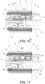
- a second driving part 74a of the second operating member 74 is configured to drive the second working member 58 to move (ex. rotate) to switch from the first working state S1 (as shown in FIG. 9 ) to the second working state S2 (as shown in FIG. 11 ), such that the second working member 58 and the front end of the blocking part 54 no longer block each other, in order to allow the second rail 24 to be moved away from the predetermined position P along the second direction D2 .
- the damping device 26 no longer provides the damping effect F to the second rail 24, the second working member 58 in the first working state S1 is prevented from tightly contacting the front end of the blocking part 54, such that the second working member 58 can be easily driven to move to switch from the first working state S1 to the second working state S2.
- the slide rail assembly according to the embodiment of the present invention has the following technical features:
Landscapes
- Engineering & Computer Science (AREA)
- Computer Hardware Design (AREA)
- General Engineering & Computer Science (AREA)
- Microelectronics & Electronic Packaging (AREA)
- Drawers Of Furniture (AREA)
- Vibration Prevention Devices (AREA)
Abstract
Description
- The present invention is related to a slide rail assembly.
- US patent number
US 10,398,228B2 - US patent number
US 10,781,855B2 - The aforementioned patents disclose slide rail assemblies arranged with damping devices for providing damping effect. However, for different market requirements, it is important to develop various slide rail products.
- This in mind, the present invention aims at providing a slide rail assembly.
- This is achieved by a slide rail assembly according to claim 1. The dependent claims pertain to corresponding further developments and improvements.
- As will be seen more clearly from the detailed description following below, the claimed slide rail assembly comprises a first rail, a second rail, a damping device and an auxiliary member. The first rail is arranged with a predetermined feature. The second rail is movable relative to the first rail. The damping device is arranged on the first rail. The auxiliary member is arranged on the second rail and configured to switch between a first predetermined state and a second predetermined state relative to the second rail. During a process of the second rail being moved relative to the first rail along a first direction, the auxiliary member in the first predetermined state is configured to abut against the damping device, such that the damping device provides damping effect to the second rail; and when the second rail is further moved relative to the first rail along the first direction, the predetermined feature is configured to abut against the auxiliary member to drive the auxiliary member to switch from the first predetermined state to the second predetermined state in order to detach the auxiliary member from the damping device, such that the damping device no longer provides damping effect to the second rail.
- In the following, the invention is further illustrated by way of example, taking reference to the accompanying drawings thereof:
-
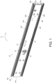
FIG. 1 is a diagram showing a slide rail assembly according to an embodiment of the present invention; -
FIG. 2 is an exploded view of the slide rail assembly comprising a first rail, a second rail and a third rail according to the embodiment of the present invention; -
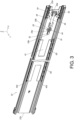
FIG. 3 is a diagram showing the first rail according to the embodiment of the present invention; -
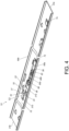
FIG. 4 is a diagram showing the second rail according to the embodiment of the present invention; -
FIG. 5 is a diagram showing the slide rail assembly in a retracted state according to the embodiment of the present invention; -
FIG. 6 is a diagram showing the first rail located at an opening position relative to the third rail with the second rail being moved relative to the first rail along a first direction according to the embodiment of the present invention; -
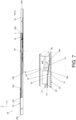
FIG. 7 is a diagram showing the first rail located at the opening position relative to the third rail with the second rail being further moved relative to the first rail along the first direction according to the embodiment of the present invention; -
FIG. 8 is a diagram showing the first rail located at the opening position relative to the third rail with the second rail being locked at a predetermined position relative to the first rail according to the embodiment of the present invention; -
FIG. 9 is a diagram showing the first rail located at the opening position relative to the third rail with the second rail being locked at the predetermined position relative to the first rail in another viewing angle according to the embodiment of the present invention; -
FIG. 10 is a diagram showing the second rail located at the predetermined position relative to the first rail with a first working member being driven to allow the second rail to move away from the predetermined position along the first direction according to the embodiment of the present invention; and -
FIG. 11 is a diagram showing the second rail located at the predetermined position relative to the first rail with a second working member being driven to allow the second rail to move away from the predetermined position along a second direction according to the embodiment of the present invention. - As shown in
FIG. 1 andFIG. 2 , aslide rail assembly 20 comprises afirst rail 22, asecond rail 24, adamping device 26, at least onepredetermined feature 28 and anauxiliary member 30 according to an embodiment of the present invention. Thesecond rail 24 is longitudinally movable relative to thefirst rail 22. In the figures, the X axis is a longitudinal direction (or a length direction or a moving direction of the slide rail), the Y axis is a transverse direction (or a lateral direction of the slide rail), and the Z axis is a vertical direction (or a height direction of the slide rail) . Preferably, theslide rail assembly 20 further comprises athird rail 32, and thefirst rail 22 is movably mounted between thethird rail 32 and thesecond rail 24. In the present embodiment, thethird rail 32 is an outer rail, thefirst rail 22 is a middle rail, and thesecond rail 24 is an inner rail, but the present invention is not limited thereto. - The
damping device 26 and the at least onepredetermined feature 28 are arranged on one of thefirst rail 22 and thesecond rail 24, and theauxiliary member 30 is arranged on the other one of thefirst rail 22 and thesecond rail 24. In the present embodiment, thedamping device 26 and the at least onepredetermined feature 28 are arranged on thefirst rail 22, and theauxiliary member 30 is arranged on thesecond rail 24. - The
third rail 32 comprises afirst wall 34a, asecond wall 34b and alongitudinal wall 36 connected between thefirst wall 34a and thesecond wall 34b of thethird rail 32. Apassage 38 is defined by thefirst wall 34a, thesecond wall 34b and thelongitudinal wall 36 of thethird rail 32, and configured to accommodate thefirst rail 22. Thethird rail 32 has afirst end part 32a and asecond end part 32b (such as a front end part and a rear end part) opposite to each other. - The
first rail 22 comprises afirst wall 40a, asecond wall 40b and alongitudinal wall 42 connected between thefirst wall 40a and thesecond wall 40b of thefirst rail 22. Apassage 44 is defined by thefirst wall 40a, thesecond wall 40b and thelongitudinal wall 42 of thefirst rail 22, and configured to accommodate thesecond rail 24. - Preferably, the
first rail 22 has afirst end part 22a and asecond end part 22b (such as a front end part and a rear end part) opposite to each other. Thedamping device 26 is arranged adjacent to thefirst end part 22a of thefirst rail 22. - Preferably, the
damping device 26 comprises afirst damping part 46 and asecond damping part 48 movable relative to each other. The first dampingpart 46 can be a cylinder body, and the second dampingpart 48 can be a rod body. The cylinder body contains a damping medium and/or an elastic member (such as a spring), and the rod body can be extended or retracted relative to the cylinder body. Such configuration is well known to those skilled in the art, no further illustration is provided for simplicity. In an alternative embodiment, the first dampingpart 46 can be a rod body, and the second dampingpart 48 can be a cylinder body. - Preferably, the
first damping part 46 is fixed to thelongitudinal wall 42 of thefirst rail 22 through at least one connectingbase 50. Thesecond damping part 48 is movable relative to thefirst damping part 46. - Preferably, one end of the second damping
part 48 away from the first dampingpart 46 is arranged (fixedly connected with) an actuatingmember 52. The actuatingmember 52 and the second dampingpart 48 can be seen as one piece. - Preferably, the at least one
predetermined feature 28 is a protrusion, and theslide rail assembly 20 can comprise one or more predetermined features 28. In the present embodiment, theslide rail assembly 20 comprises twopredetermined features 28, but the present invention is not limited thereto. The predetermined features 28 are arranged on thelongitudinal wall 42 of thefirst rail 22, and thepredetermined features 28 are located between two ends (afirst end 26a and asecond end 26b, such as a front end and a rear end shown inFIG. 3 ) of the dampingdevice 26. In the present embodiment, the predetermined features 28 are arranged adjacent to the second dampingpart 48 of the dampingdevice 26. The predetermined features 28 and the second dampingpart 48 are located at different positions on thelongitudinal wall 42 of thefirst rail 22 along the height direction of the slide rail. - Preferably, the
first rail 22 further comprises a blockingpart 54 adjacent to thefirst end part 22a of the first rail 22 (please also refer toFIG. 3 ). The blockingpart 54 is (transversally or laterally) protruded relative to thelongitudinal wall 42 of thefirst rail 22, but the present invention is not limited thereto. - The
second rail 24 has afirst end part 24a and asecond end part 24b (such as a front end part and a rear end part) opposite to each other. Theslide rail assembly 20 further comprises a first workingmember 56 and/or a second workingmember 58 movably mounted on thesecond rail 24. In the present embodiment, the first workingmember 56 and the second workingmember 58 are pivoted to thesecond rail 24 through afirst shaft member 60 and asecond shaft member 62 respectively. Thesecond rail 24 is arranged with an auxiliary elastic member. The auxiliary elastic member comprises a firstelastic part 66a and a secondelastic part 66b configured to provide elastic forces to the first workingmember 56 and the second workingmember 58 respectively (please also refer toFIG. 4 andFIG. 9 ). - Preferably, the
second rail 24 comprises afirst wall 68a, asecond wall 68b and alongitudinal wall 70 connected between thefirst wall 68a and thesecond wall 68b of thesecond rail 24. Theauxiliary member 30 is arranged on thelongitudinal wall 70 of thesecond rail 24. Furthermore, theauxiliary member 30 is an elastic component, such as an elastic piece, but the present invention is not limited thereto. Theauxiliary member 30 comprises a first connectingpart 31a, a second connectingpart 31b and amiddle part 33 located between the first connectingpart 31a and the second connectingpart 31b. For example, themiddle part 33 is extended between the first connectingpart 31a and the second connectingpart 31b (please also refer toFigure 4 ). The first connectingportion 31a and the second connectingportion 31b are connected (such as fixed) to thelongitudinal wall 70 of thesecond rail 24. Themiddle part 33 is transversally or laterally raised relative to thelongitudinal wall 70 of thesecond rail 24. A space 35 (such as an opening, but the present invention is not limited thereto) is formed between themiddle part 33 and the first connectingpart 31a, and themiddle part 33 is arranged with apredetermined wall 37 located at an edge of the space 35 (please also refer toFIG. 4 ). - Preferably, a first guiding section G1 is arranged between the
middle part 33 and the first connectingpart 31a, and a second guiding section G2 is arranged between themiddle part 33 and the second connectingpart 31b. The first guiding section G1 and the second guiding section G2 can be inclined surfaces or arc surfaces. - Preferably, the
slide rail assembly 20 further comprises at least one operating member. In the present embodiment, theslide rail assembly 20 comprises afirst operating member 72 and asecond operating member 74 configured to respectively drive the first workingmember 56 and the second workingmember 58 to move. Thefirst operating member 72 and thesecond operating member 74 are operatively connected to the first workingmember 56 and the second workingmember 58 respectively. - Preferably, the
slide rail assembly 20 further comprises at least one firstslide assisting device 76. The at least one firstslide assisting device 76 comprises a plurality of first balls B1. The at least one firstslide assisting device 76 is movably mounted in thepassage 38 of thethird rail 32 to improve moving smoothness between thefirst rail 22 and thethird rail 32. On the other hand, theslide rail assembly 20 further comprises a secondslide assisting device 78. The secondslide assisting device 78 comprises a plurality of second balls B2. The secondslide assisting device 78 is movably mounted in thepassage 44 of thefirst rail 22 to improve moving smoothness between thesecond rail 24 and thefirst rail 22. - As shown in
FIG. 5 , theslide rail assembly 20 is in a retracted state. Furthermore, thefirst rail 22 is retracted relative to thethird rail 32, and thesecond rail 24 is located at a retracted position R relative to thefirst rail 22. Theauxiliary member 30 is separated from the dampingdevice 26 along the longitudinal direction. Theauxiliary member 30 is in a first predetermined state K1 relative to thesecond rail 24, and the dampingdevice 26 is in a damping preparation state (for example, the second dampingpart 48 is extended relative to the first damping part 46). The first and second workingmembers part 54 along the longitudinal direction. An auxiliary space M is defined between the first workingmember 56 and the second workingmember 58. Thepredetermined feature 28 has a first predetermined end and a second predetermined end opposite to each other. At least one of the first predetermined end and the second predetermined end is arranged with a guiding feature. In the present embodiment, the first predetermined end and the second predetermined end are arranged with afirst guiding feature 29a and asecond guiding feature 29b respectively, and thefirst guiding feature 29a and thesecond guiding feature 29b can be inclined surfaces or arc surfaces. - As shown in
FIG. 5 to FIG. 7 , during a process of thesecond rail 24 being moved relative to thefirst rail 22 from the retracted position R (as shown inFIG. 5 ) along a first direction D1 (such as an opening direction), theauxiliary member 30 is configured to drive the dampingdevice 26. Specifically, theauxiliary member 30 in the first predetermined state K1 is configured to abut against the damping device 26 (as shown inFIG. 6 ) to drive the dampingdevice 26 to provide damping effect F (as shown inFigure 7 ), such as providing damping effect F to thesecond rail 24. - Furthermore, when the
first rail 22 is located at an opening position J relative to thethird rail 32, thefirst end part 22a of thefirst rail 22 is extended beyond thefirst end part 32a of thethird rail 32, and thefirst rail 22 is configured to be locked at the opening position J relative to thethird rail 32. Such configuration is well known to those skilled in the art, no further illustration is provided for simplicity. During a process of thesecond rail 24 being moved along the first direction D1 relative to thefirst rail 22 located at the opening position J, thepredetermined wall 37 of theauxiliary member 30 in the first predetermined state K1 is configured to abut against the actuating member 52 (as shown inFIG. 6 ) on the second dampingpart 48 to retract the second dampingpart 48 relative to the first dampingpart 46, so as to drive the dampingdevice 26 to provide the damping effect F (as shown inFIG. 7 ). - As shown in
FIG. 8 , when thesecond rail 24 is further moved along the first direction D1 relative to thefirst rail 22, the predetermined feature 28 (such as thefirst guiding feature 29a of the predetermined feature 28) is configured to abut against the auxiliary member 30 (such as the first guiding section G1 of the auxiliary member 30) in order to drive theauxiliary member 30 to switch from the first predetermined state K1 to a second predetermined state K2. For example, theauxiliary member 30 is elastically deformed, such that the actuatingmember 52 on the second dampingpart 48 of the dampingdevice 26 no longer blocks a moving path of thepredetermined wall 37 of theauxiliary member 30, so as to detach thepredetermined wall 37 of theauxiliary member 30 from the actuatingmember 52 on the second dampingpart 48 of the dampingdevice 26. In other words, theauxiliary member 30 no longer drives the dampingdevice 26, such that the dampingdevice 26 no longer provides the damping effect F to thesecond rail 24. Meanwhile, the second dampingpart 48 is extended relative to the first dampingpart 46 again. - As shown in
FIG. 8 andFIG. 9 , when thesecond rail 24 is further moved along the first direction D1 relative to thefirst rail 22 to a predetermined position P (such as an extended position), the first and second workingmembers part 54 respectively in order to block the blockingpart 54, and the blockingpart 54 is accommodated in the auxiliary space M in order to prevent thesecond rail 24 from being moved away from the predetermined position P. For example, thesecond rail 24 is prevented from being moved away from the predetermined position P along the first direction D1 or a second direction D2 (such as a retracting direction). When thesecond rail 24 is located at the predetermined position P relative to thefirst rail 22, thefirst end part 24a of thesecond rail 24 is extended beyond thefirst end part 22a of thefirst rail 22. As such, theslide rail assembly 20 is in an extended state. Such configuration is well known to those skilled in the art, no further illustration is provided for simplicity. - As shown in
FIG. 9 andFIG. 10 , when thesecond rail 24 is located at the predetermined position P relative to thefirst rail 22 and when a user applies a first force F1 to thefirst operating member 72, afirst driving part 72a of thefirst operating member 72 is configured to drive the first workingmember 56 to move (ex. rotate) to switch from the first working state S1 (as shown inFIG. 9 ) to a second working state S2 (as shown inFIG. 10 ), such that the first workingmember 56 and the rear end of the blockingpart 54 no longer block each other, in order to allow thesecond rail 24 to be moved away from the predetermined position P along the first direction D1. - As shown in
FIG. 9 andFIG. 11 , , when thesecond rail 24 is located at the predetermined position P relative to thefirst rail 22 and when the user applies a second force F2 to thefirst operating member 72, asecond driving part 74a of thesecond operating member 74 is configured to drive the second workingmember 58 to move (ex. rotate) to switch from the first working state S1 (as shown inFIG. 9 ) to the second working state S2 (as shown inFIG. 11 ), such that the second workingmember 58 and the front end of the blockingpart 54 no longer block each other, in order to allow thesecond rail 24 to be moved away from the predetermined position P along the second direction D2 . Moreover, since the dampingdevice 26 no longer provides the damping effect F to thesecond rail 24, the second workingmember 58 in the first working state S1 is prevented from tightly contacting the front end of the blockingpart 54, such that the second workingmember 58 can be easily driven to move to switch from the first working state S1 to the second working state S2. - Therefore, the slide rail assembly according to the embodiment of the present invention has the following technical features:
- 1. When the user moves the
second rail 24 along the first direction D1 relative to thefirst rail 22 to be close to the predetermined position P, theauxiliary member 30 is configured to abut against the dampingdevice 26 to provide the damping effect to thesecond rail 24. As such, the user can notice that thesecond rail 24 is about to reach the predetermined position P. Moreover, impact before thesecond rail 24 reaches the predetermined position P can be reduced. - 2. When the
second rail 24 is moved relative to thefirst rail 22 along the first direction D1 to be close to the predetermined position P, the damping effect F of the dampingdevice 26 has been provided. When thesecond rail 24 is further moved relative to thefirst rail 22 along the first direction D1 to reach the predetermined position P, the dampingdevice 26 no longer provides the damping effect F to thesecond rail 24. As such, it can be prevented that one of thefirst work member 56 and the second workingmember 58 in the first working state S1 is in close contact with the blockingpart 54 to hardly drive the first workingmember 56 or the second workingmember 58 to move. - 3. The damping
device 26 is arranged adjacent to thefirst end part 22a of thefirst rail 22. When thesecond rail 24 is moved along the first direction D1, the dampingdevice 26 is directly driven by theauxiliary member 30 to provide the damping effect F. In contrast to the prior art, the damping effect in the embodiment of the present invention is more direct and obvious.
Claims (11)
- A slide rail assembly (20), comprising:a first rail (22) arranged with a predetermined feature (28) ;a second rail (24) movable relative to the first rail (22);a damping device (26) arranged on the first rail (22); andcharacterized by:an auxiliary member (30) arranged on the second rail (24), wherein the auxiliary member (30) is configured to switch between a first predetermined state and a second predetermined state relative to the second rail (24);wherein during a process of the second rail (24) being moved relative to the first rail (22) along a first direction, the auxiliary member (30) in the first predetermined state is configured to abut against the damping device (26), such that the damping device (26) provides damping effect to the second rail (24); andwherein when the second rail (24) is further moved relative to the first rail (22) along the first direction, the predetermined feature (28) is configured to abut against the auxiliary member (30) to drive the auxiliary member (30) to switch from the first predetermined state to the second predetermined state in order to detach the auxiliary member (30) from the damping device (26), such that the damping device (26) no longer provides damping effect to the second rail (24).
- The slide rail assembly of claim 1, further characterized by a third rail (32), wherein the first rail (22) is movably mounted between the third rail (32) and the second rail (24).
- The slide rail assembly of claim 1 or 2, characterized in that the first rail (22) has a first end part and a second end part opposite to each other, the damping device (26) is arranged adjacent to the first end part of the first rail (22).
- The slide rail assembly of any of claims 1-3, characterized in that the first rail (22) is further arranged with a blocking part (54), and the slide rail assembly (20) further comprises a first working member (56) and a second working member (58) movably mounted on the second rail (24) ; wherein when the second rail (24) is further moved relative to the first rail (22) along the first direction to a predetermined position, the first working member (56) and the second working member (58) are configured to be located adjacent to two opposite ends of the blocking part (54) respectively in order to prevent the second rail (24) from being moved away from the predetermined position.
- The slide rail assembly of claim 4, characterized in that the first working member (56) and the second working member (58) are pivoted to the second rail (24), and the second rail (24) is arranged with a first elastic part and a second elastic part configured to provide elastic forces to the first working member (56) and the second working member (58) respectively.
- The slide rail assembly of claim 5, further characterized by at least one operating member (72, 74) configured to drive the first working member (56) and the second working member (58) to move.
- The slide rail assembly of any of claims 1-6, characterized in that the predetermined feature (28) is a protruded part.
- The slide rail assembly of claim 7, characterized in that the predetermined feature (28) has a first predetermined end and a second predetermined end.
- The slide rail assembly of claim 8, characterized in that at least one of the first predetermined end and the second predetermined end is arranged with a guiding feature.
- The slide rail assembly of any of claims 1-9, characterized in that the damping device (26) comprises a first damping part (46) and a second damping part (48) movable relative to each other.
- The slide rail assembly of any of claims 1-10, wherein when the second rail (24) is further moved relative to the first rail (22) along the first direction, the predetermined feature (28) is configured to abut against the auxiliary member (30) to elastically deform the auxiliary member (30) to switch from the first predetermined state to the second predetermined state, in order to detach the auxiliary member (30) from the damping device (26), such that the damping device (26) no longer provides damping effect to the second rail (24).
Applications Claiming Priority (1)
| Application Number | Priority Date | Filing Date | Title |
|---|---|---|---|
| TW112143583A TWI847909B (en) | 2023-11-09 | 2023-11-09 | Slide rail assembly |
Publications (2)
| Publication Number | Publication Date |
|---|---|
| EP4552531A1 true EP4552531A1 (en) | 2025-05-14 |
| EP4552531B1 EP4552531B1 (en) | 2025-10-15 |
Family
ID=91810358
Family Applications (1)
| Application Number | Title | Priority Date | Filing Date |
|---|---|---|---|
| EP24186229.1A Active EP4552531B1 (en) | 2023-11-09 | 2024-07-03 | Slide rail assembly |
Country Status (4)
| Country | Link |
|---|---|
| US (1) | US12575674B2 (en) |
| EP (1) | EP4552531B1 (en) |
| JP (1) | JP7729953B2 (en) |
| TW (1) | TWI847909B (en) |
Citations (4)
| Publication number | Priority date | Publication date | Assignee | Title |
|---|---|---|---|---|
| AT410507B (en) * | 2000-03-10 | 2003-05-26 | Blum Gmbh Julius | Guide rail system for drawer consists of rail attached to carcass of item of furniture, second rail attached to drawer and intermediate rail mounted on rollers between them, shock absorber being mounted between two of rails |
| TW201836524A (en) * | 2017-04-12 | 2018-10-16 | 川湖科技股份有限公司 | Slide rail assembly |
| US10398228B2 (en) | 2017-04-12 | 2019-09-03 | King Slide Works Co., Ltd. | Slide rail assembly |
| US10781855B2 (en) | 2016-11-01 | 2020-09-22 | King Slide Works Co., Ltd. | Slide rail assembly |
Family Cites Families (3)
| Publication number | Priority date | Publication date | Assignee | Title |
|---|---|---|---|---|
| JPH0513223Y2 (en) | 1987-04-02 | 1993-04-07 | ||
| US6935710B2 (en) | 2003-03-05 | 2005-08-30 | King Slide Works Co., Ltd. | Two-way retainer for a slide track assembly of drawers |
| TWI767859B (en) * | 2021-10-25 | 2022-06-11 | 南俊國際股份有限公司 | Slide assembly |
-
2023
- 2023-11-09 TW TW112143583A patent/TWI847909B/en active
-
2024
- 2024-05-31 US US18/680,028 patent/US12575674B2/en active Active
- 2024-07-03 EP EP24186229.1A patent/EP4552531B1/en active Active
- 2024-07-03 JP JP2024107110A patent/JP7729953B2/en active Active
Patent Citations (4)
| Publication number | Priority date | Publication date | Assignee | Title |
|---|---|---|---|---|
| AT410507B (en) * | 2000-03-10 | 2003-05-26 | Blum Gmbh Julius | Guide rail system for drawer consists of rail attached to carcass of item of furniture, second rail attached to drawer and intermediate rail mounted on rollers between them, shock absorber being mounted between two of rails |
| US10781855B2 (en) | 2016-11-01 | 2020-09-22 | King Slide Works Co., Ltd. | Slide rail assembly |
| TW201836524A (en) * | 2017-04-12 | 2018-10-16 | 川湖科技股份有限公司 | Slide rail assembly |
| US10398228B2 (en) | 2017-04-12 | 2019-09-03 | King Slide Works Co., Ltd. | Slide rail assembly |
Also Published As
| Publication number | Publication date |
|---|---|
| JP2025079296A (en) | 2025-05-21 |
| US20250151900A1 (en) | 2025-05-15 |
| TW202519143A (en) | 2025-05-16 |
| US12575674B2 (en) | 2026-03-17 |
| EP4552531B1 (en) | 2025-10-15 |
| TWI847909B (en) | 2024-07-01 |
| JP7729953B2 (en) | 2025-08-26 |
Similar Documents
| Publication | Publication Date | Title |
|---|---|---|
| EP3387952B1 (en) | Slide rail assembly | |
| EP3292788B1 (en) | Slide rail assembly | |
| EP4035568B1 (en) | Slide rail assembly | |
| EP4018883A1 (en) | Slide rail assembly | |
| EP3763247B1 (en) | Slide rail assembly | |
| EP3387950A1 (en) | Slide rail assembly | |
| EP3387949A1 (en) | Slide rail assembly | |
| EP3763246B1 (en) | Slide rail assembly | |
| EP4327696A1 (en) | Slide rail assembly | |
| EP3461244B1 (en) | Slide rail assembly and driving mechanism thereof | |
| JP6995921B2 (en) | Slide rail assembly | |
| EP4570126A1 (en) | Slide rail assembly | |
| US10918209B1 (en) | Slide rail assembly | |
| TWI704887B (en) | Slide rail assembly | |
| EP3563723B1 (en) | Slide rail assembly | |
| JP7072089B2 (en) | Slide rail assembly | |
| EP4552531B1 (en) | Slide rail assembly | |
| TWI818694B (en) | Slide rail assembly and slide rail kit thereof | |
| CN120007696A (en) | Slide rail assembly | |
| CN112754197A (en) | Sliding rail assembly | |
| CN112386025A (en) | Sliding rail assembly | |
| CN117652800A (en) | Slide rail assembly | |
| EP4578340A1 (en) | Slide rail assembly | |
| CN113273829B (en) | Sliding rail assembly | |
| CN112576624B (en) | Sliding rail assembly |
Legal Events
| Date | Code | Title | Description |
|---|---|---|---|
| PUAI | Public reference made under article 153(3) epc to a published international application that has entered the european phase |
Free format text: ORIGINAL CODE: 0009012 |
|
| STAA | Information on the status of an ep patent application or granted ep patent |
Free format text: STATUS: REQUEST FOR EXAMINATION WAS MADE |
|
| 17P | Request for examination filed |
Effective date: 20250110 |
|
| AK | Designated contracting states |
Kind code of ref document: A1 Designated state(s): AL AT BE BG CH CY CZ DE DK EE ES FI FR GB GR HR HU IE IS IT LI LT LU LV MC ME MK MT NL NO PL PT RO RS SE SI SK SM TR |
|
| GRAP | Despatch of communication of intention to grant a patent |
Free format text: ORIGINAL CODE: EPIDOSNIGR1 |
|
| STAA | Information on the status of an ep patent application or granted ep patent |
Free format text: STATUS: GRANT OF PATENT IS INTENDED |
|
| INTG | Intention to grant announced |
Effective date: 20250714 |
|
| GRAS | Grant fee paid |
Free format text: ORIGINAL CODE: EPIDOSNIGR3 |
|
| GRAA | (expected) grant |
Free format text: ORIGINAL CODE: 0009210 |
|
| STAA | Information on the status of an ep patent application or granted ep patent |
Free format text: STATUS: THE PATENT HAS BEEN GRANTED |
|
| AK | Designated contracting states |
Kind code of ref document: B1 Designated state(s): AL AT BE BG CH CY CZ DE DK EE ES FI FR GB GR HR HU IE IS IT LI LT LU LV MC ME MK MT NL NO PL PT RO RS SE SI SK SM TR |
|
| REG | Reference to a national code |
Ref country code: GB Ref legal event code: FG4D Ref country code: CH Ref legal event code: F10 Free format text: ST27 STATUS EVENT CODE: U-0-0-F10-F00 (AS PROVIDED BY THE NATIONAL OFFICE) Effective date: 20251015 |
|
| REG | Reference to a national code |
Ref country code: DE Ref legal event code: R096 Ref document number: 602024000939 Country of ref document: DE |
|
| REG | Reference to a national code |
Ref country code: IE Ref legal event code: FG4D |
|
| REG | Reference to a national code |
Ref country code: NL Ref legal event code: MP Effective date: 20251015 |
|
| REG | Reference to a national code |
Ref country code: AT Ref legal event code: MK05 Ref document number: 1846155 Country of ref document: AT Kind code of ref document: T Effective date: 20251015 |
|
| PG25 | Lapsed in a contracting state [announced via postgrant information from national office to epo] |
Ref country code: NL Free format text: LAPSE BECAUSE OF FAILURE TO SUBMIT A TRANSLATION OF THE DESCRIPTION OR TO PAY THE FEE WITHIN THE PRESCRIBED TIME-LIMIT Effective date: 20251015 |
|
| PG25 | Lapsed in a contracting state [announced via postgrant information from national office to epo] |
Ref country code: ES Free format text: LAPSE BECAUSE OF FAILURE TO SUBMIT A TRANSLATION OF THE DESCRIPTION OR TO PAY THE FEE WITHIN THE PRESCRIBED TIME-LIMIT Effective date: 20251015 |
|
| REG | Reference to a national code |
Ref country code: LT Ref legal event code: MG9D |
|
| PG25 | Lapsed in a contracting state [announced via postgrant information from national office to epo] |
Ref country code: NO Free format text: LAPSE BECAUSE OF FAILURE TO SUBMIT A TRANSLATION OF THE DESCRIPTION OR TO PAY THE FEE WITHIN THE PRESCRIBED TIME-LIMIT Effective date: 20260115 |
|
| PG25 | Lapsed in a contracting state [announced via postgrant information from national office to epo] |
Ref country code: AT Free format text: LAPSE BECAUSE OF FAILURE TO SUBMIT A TRANSLATION OF THE DESCRIPTION OR TO PAY THE FEE WITHIN THE PRESCRIBED TIME-LIMIT Effective date: 20251015 Ref country code: HR Free format text: LAPSE BECAUSE OF FAILURE TO SUBMIT A TRANSLATION OF THE DESCRIPTION OR TO PAY THE FEE WITHIN THE PRESCRIBED TIME-LIMIT Effective date: 20251015 Ref country code: FI Free format text: LAPSE BECAUSE OF FAILURE TO SUBMIT A TRANSLATION OF THE DESCRIPTION OR TO PAY THE FEE WITHIN THE PRESCRIBED TIME-LIMIT Effective date: 20251015 |
|
| PG25 | Lapsed in a contracting state [announced via postgrant information from national office to epo] |
Ref country code: RS Free format text: LAPSE BECAUSE OF FAILURE TO SUBMIT A TRANSLATION OF THE DESCRIPTION OR TO PAY THE FEE WITHIN THE PRESCRIBED TIME-LIMIT Effective date: 20260115 |
|
| PG25 | Lapsed in a contracting state [announced via postgrant information from national office to epo] |
Ref country code: IS Free format text: LAPSE BECAUSE OF FAILURE TO SUBMIT A TRANSLATION OF THE DESCRIPTION OR TO PAY THE FEE WITHIN THE PRESCRIBED TIME-LIMIT Effective date: 20260215 |
|
| PG25 | Lapsed in a contracting state [announced via postgrant information from national office to epo] |
Ref country code: PT Free format text: LAPSE BECAUSE OF FAILURE TO SUBMIT A TRANSLATION OF THE DESCRIPTION OR TO PAY THE FEE WITHIN THE PRESCRIBED TIME-LIMIT Effective date: 20260216 |
|
| PG25 | Lapsed in a contracting state [announced via postgrant information from national office to epo] |
Ref country code: PL Free format text: LAPSE BECAUSE OF FAILURE TO SUBMIT A TRANSLATION OF THE DESCRIPTION OR TO PAY THE FEE WITHIN THE PRESCRIBED TIME-LIMIT Effective date: 20251015 |
|
| PG25 | Lapsed in a contracting state [announced via postgrant information from national office to epo] |
Ref country code: LV Free format text: LAPSE BECAUSE OF FAILURE TO SUBMIT A TRANSLATION OF THE DESCRIPTION OR TO PAY THE FEE WITHIN THE PRESCRIBED TIME-LIMIT Effective date: 20251015 |
|
| PG25 | Lapsed in a contracting state [announced via postgrant information from national office to epo] |
Ref country code: BG Free format text: LAPSE BECAUSE OF FAILURE TO SUBMIT A TRANSLATION OF THE DESCRIPTION OR TO PAY THE FEE WITHIN THE PRESCRIBED TIME-LIMIT Effective date: 20251015 |