EP4552513A1 - Aerosol generating assembly comprising a heating element capable of exothermic reaction - Google Patents
Aerosol generating assembly comprising a heating element capable of exothermic reaction Download PDFInfo
- Publication number
- EP4552513A1 EP4552513A1 EP23208977.1A EP23208977A EP4552513A1 EP 4552513 A1 EP4552513 A1 EP 4552513A1 EP 23208977 A EP23208977 A EP 23208977A EP 4552513 A1 EP4552513 A1 EP 4552513A1
- Authority
- EP
- European Patent Office
- Prior art keywords
- aerosol generating
- heating element
- aerosol
- heater
- fluid
- Prior art date
- Legal status (The legal status is an assumption and is not a legal conclusion. Google has not performed a legal analysis and makes no representation as to the accuracy of the status listed.)
- Pending
Links
Images

Classifications
-
- A—HUMAN NECESSITIES
- A24—TOBACCO; CIGARS; CIGARETTES; SIMULATED SMOKING DEVICES; SMOKERS' REQUISITES
- A24F—SMOKERS' REQUISITES; MATCH BOXES; SIMULATED SMOKING DEVICES
- A24F42/00—Simulated smoking devices other than electrically operated; Component parts thereof; Manufacture or testing thereof
- A24F42/10—Devices with chemical heating means
-
- A—HUMAN NECESSITIES
- A24—TOBACCO; CIGARS; CIGARETTES; SIMULATED SMOKING DEVICES; SMOKERS' REQUISITES
- A24D—CIGARS; CIGARETTES; TOBACCO SMOKE FILTERS; MOUTHPIECES OF CIGARS OR CIGARETTES; MANUFACTURE OF TOBACCO SMOKE FILTERS OR MOUTHPIECES
- A24D1/00—Cigars; Cigarettes
- A24D1/20—Cigarettes specially adapted for simulated smoking devices
-
- A—HUMAN NECESSITIES
- A24—TOBACCO; CIGARS; CIGARETTES; SIMULATED SMOKING DEVICES; SMOKERS' REQUISITES
- A24F—SMOKERS' REQUISITES; MATCH BOXES; SIMULATED SMOKING DEVICES
- A24F40/00—Electrically operated smoking devices; Component parts thereof; Manufacture thereof; Maintenance or testing thereof; Charging means specially adapted therefor
-
- A—HUMAN NECESSITIES
- A24—TOBACCO; CIGARS; CIGARETTES; SIMULATED SMOKING DEVICES; SMOKERS' REQUISITES
- A24F—SMOKERS' REQUISITES; MATCH BOXES; SIMULATED SMOKING DEVICES
- A24F40/00—Electrically operated smoking devices; Component parts thereof; Manufacture thereof; Maintenance or testing thereof; Charging means specially adapted therefor
- A24F40/40—Constructional details, e.g. connection of cartridges and battery parts
- A24F40/46—Shape or structure of electric heating means
-
- A—HUMAN NECESSITIES
- A24—TOBACCO; CIGARS; CIGARETTES; SIMULATED SMOKING DEVICES; SMOKERS' REQUISITES
- A24F—SMOKERS' REQUISITES; MATCH BOXES; SIMULATED SMOKING DEVICES
- A24F40/00—Electrically operated smoking devices; Component parts thereof; Manufacture thereof; Maintenance or testing thereof; Charging means specially adapted therefor
- A24F40/40—Constructional details, e.g. connection of cartridges and battery parts
- A24F40/48—Fluid transfer means, e.g. pumps
-
- A—HUMAN NECESSITIES
- A24—TOBACCO; CIGARS; CIGARETTES; SIMULATED SMOKING DEVICES; SMOKERS' REQUISITES
- A24D—CIGARS; CIGARETTES; TOBACCO SMOKE FILTERS; MOUTHPIECES OF CIGARS OR CIGARETTES; MANUFACTURE OF TOBACCO SMOKE FILTERS OR MOUTHPIECES
- A24D1/00—Cigars; Cigarettes
- A24D1/22—Cigarettes with integrated combustible heat sources, e.g. with carbonaceous heat sources
-
- A—HUMAN NECESSITIES
- A24—TOBACCO; CIGARS; CIGARETTES; SIMULATED SMOKING DEVICES; SMOKERS' REQUISITES
- A24F—SMOKERS' REQUISITES; MATCH BOXES; SIMULATED SMOKING DEVICES
- A24F40/00—Electrically operated smoking devices; Component parts thereof; Manufacture thereof; Maintenance or testing thereof; Charging means specially adapted therefor
- A24F40/30—Devices using two or more structurally separated inhalable precursors, e.g. using two liquid precursors in two cartridges
Definitions
- the present invention concerns an aerosol generating assembly.
- said aerosol generating assembly comprises an aerosol generating device and an aerosol generating article comprising an aerosol generating substrate able to form aerosol when being heated.
- the aerosol generating article is configured to operate with the aerosol generating device.
- Such type of aerosol generating device also known as heat-not-burn device, is adapted to heat, rather than burn, the aerosol generating substrate to generate aerosol for inhalation.
- such devices are heat-not-burn devices.
- Devices of this type generate aerosol or vapour by heating an aerosol generating substrate that typically comprises moist leaf tobacco or other suitable vaporizable material to a temperature typically in the range of 150°C to 350°C. Heating an aerosol generating substrate, but not combusting or burning it, releases aerosol that comprises the components sought by the user but not the toxic and carcinogenic by-products of combustion and burning.
- the aerosol produced by heating the tobacco or other vaporizable material does not typically comprise the burnt or bitter taste resulting from combustion and burning that can be unpleasant for the user and so the substrate does not therefore require the sugars and other additives that are typically added to such materials to make the smoke and/or vapour more palatable for the user.
- the aerosol generating article comprises an aerosol generating part and a mouthpiece portion.
- the aerosol generating part comprises an aerosol generating substrate intended to be heated to generate aerosol.
- the aerosol generating article, in particular the aerosol generating part is intended to be received at least partially within a receiving chamber of the aerosol generating device, wherein the aerosol generating part is heated.
- the mouthpiece portion allows the aerosol to cool down and to transfer from the aerosol generating part to the outlet of the article.
- the aerosol generating part in particular the aerosol generating substrate, is heated enough, to carry out an optimal aerosol generation.
- the aerosol generating device with powerful heaters capable of heating the aerosol generating substrate when the article is received in the receiving chamber of the device.
- the heater may be constantly heated for several minutes resulting in high energy consumption.
- such heaters are detrimental to the battery run time and to the battery lifetime. Additionally, these heaters do not allow fast heating: a pre-heating phase is necessary before the aerosol generating substrate is able to generate aerosol.
- One of the aims of the invention is to provide an aerosol generating assembly wherein the heating of the aerosol generating part can be improved, the energy consumption of the battery can be reduced and the battery lifetime of the aerosol generating device so be increased. Additionally, heating of the aerosol generating part can be performed very quickly such that a pre-heating phase can be eliminated or at least reduced.
- the invention relates to an aerosol generating assembly comprising:
- the aerosol generating part of the aerosol generating substrate is heated by the heating element through exothermic reaction of the heating element when it is in contact with the heated fluid.
- This makes it possible to reduce the use of the battery for the heating of the substrate (to power the first heater), at least during a phase of heating the substrate from a low temperature (for example ambient temperature) to a high temperature (for example a temperature high enough to generate aerosol), and thus the battery lifetime of the device is increased.
- a low temperature for example ambient temperature
- a high temperature for example a temperature high enough to generate aerosol
- the heat of the heated fluid can also be used to heat the substrate.
- the exothermic reaction releases an amount of energy comprised between 500 J and 1200 J. This amount of energy helps heating the aerosol generating substrate for example from ambient temperature until 300°C or 350°C and makes it possible to reduce the power consumption or use of the first heater.
- the fluid comprises water.
- the fluid is water.
- the mass proportion of the water in the total amount of the fluid can be comprised between 10% and 100%, advantageously between 20% and 90%, and preferably between 30% and 80%.
- the heating element is made up of a heating material comprising an active component undergoing the exothermic reaction when in contact with the heated fluid, the active component comprising:
- the heating material is made up of:
- the heating material is made up of calcium oxide with a mass proportion of 33%.
- the heating material comprises a binder mixed with the active component.
- the binder may comprise the binder comprises: cellulose derivative, cellulose ester, plant-derived polysaccharide, algae-derived polysaccharide, microorganism-derived polysaccharide, crustacea-derived polysaccharide, starch, protein, polyvinyl alcohol, polyphosphoric acid, sodium polyacrylate, polyvinylpyrrolidone and combinations thereof.
- the binder comprises at least one of the following components: carboxy-methyl cellulose (CMC), pectin, guar gum, xanthan gum, tamarind gum, carrageenan and/or polyvinyl alcohol.
- the heating material is made up of a binder with a mass proportion of 5%.
- the heating material is made up of calcium oxide with a mass proportion of 33% and a binder with a mass proportion of 5%.
- the active component is held together to form a cohesive whole mechanically and chemically.
- the heating material may be further coated with a moisture barrier.
- the moisture barrier may be polysaccharide.
- a binder taken from the previous list may be used as the moisture barrier.
- the barrier coating prevents the heating material from absorbing moisture from the atmosphere during storage.
- the aerosol generating substrate comprises a tobacco substrate.
- the heating of the aerosol generating substrate leads to the generation of tobacco aerosol.
- the aerosol generating device comprises a receiving chamber designed to receive at least a portion of the aerosol generating article, the receiving chamber comprising at least a heating element receiving portion for receiving the heating element; the aerosol generating device comprising a fluid transfer system configured for transferring the heated fluid in the at least one heating element receiving portion of the receiving chamber.
- the aerosol generating assembly presents an easy to manufacture and efficient structure to put the heating element in contact with the heated fluid.
- the receiving chamber comprises at least an aerosol generating part receiving portion adapted to receive the aerosol generating part; the heating element comprising at least a tubular channel comprising a first end designed to be put in fluidic communication with the fluid transfer system and a second end fluidically connected to the aerosol generating part.
- the heated fluid also reaches the aerosol generating part receiving portion, and is put in contact with the aerosol generating substrate when the article is mounted onto the device.
- the heated fluid can be mixed with the generated aerosol and can be inhaled by the user.
- the heating element comprises a single tubular channel, the heating element comprising a single tubular wall delimiting the single tubular channel.
- the heating element presents an easy to manufacture and efficient structure to put the fluid transfer system and the aerosol generating part receiving portion in fluidic communication. Also, the area of the reaction interface between the heating element and the heated fluid is increased.
- the heating element comprises several tubular channels, the heating element comprising a honeycomb structure delimiting the tubular channels.
- the area of the reaction interface between the heating element and the heated fluid is further increased.
- the heating element is such that it is able to reach a temperature of up to about 200°C.
- the aerosol generating device comprises at least a receiving chamber wall delimiting the receiving chamber, the at least one receiving chamber wall comprising at least a heat spreading portion, for example made up of metal, configured for transferring heat generated by the at least one heating element receiving portion to the aerosol generating part receiving portion.
- the heat generated by the heating element is transferred optimally to the aerosol generating part receiving portion. This makes it possible to efficiently accumulate heat in the aerosol generating part receiving portion.
- the at least one heat spreading portion presents a thermal conductivity of between 10 W m -1 K -1 and 50 W m -1 K -1 .
- the at least one heat spreading portion is made up of stainless steel, such as stainless steel 304 or stainless steel 316.
- the aerosol generating device comprises an outer wall, at least a part of the outer wall extending around the receiving chamber comprising a thermal insulator portion configured for preventing heat loss of the aerosol generating part receiving portion.
- the at least one thermal insulator portion presents a thermal conductivity of between 200 W m -1 K -1 and 250 W m -1 K -1 .
- the at least one thermal insulator portion is made up of metal, preferably aluminium.
- the first heater is configured for heating the receiving chamber, in particular the aerosol generating part receiving portion.
- the first heater is an electric heater film arranged around the receiving chamber, in particular around the aerosol generating part receiving portion.
- the first heater is an inductive coil positioned about the receiving chamber, advantageously around the aerosol generating part receiving portion, and capable of heating internal susceptor(s) comprised within the aerosol generating part.
- the mass proportion of the aerosol forming agent in the aerosol generating substrate can be comprised between 5% and 50%, advantageously between 10% and 40%, and preferably between 20% and 30% in dry weight basis of the aerosol generating substrate.
- the fluid reservoir is removably mounted on the device body.
- the aerosol generating device comprises a cartomizer, the cartomizer comprising the second heater and the fluid reservoir, the cartomizer being removably mounted on the device body.
- the reservoir of fluid and/or the second heater can be easily replaced.
- the aerosol generating device comprises:
- energy consumption from the first heater can be reduced, in particular when a significant amount of energy is needed, for example when the aerosol generating substrate is heated from ambient temperature to a temperature high enough to generate aerosol.
- aerosol generating device or “ device” may include a vaping device to deliver an aerosol to a user, including an aerosol for vaping, by means of a heater element explained in further detail below.
- the device may be portable.
- “Portable” may refer to the device being for use when held by a user.
- the device may be adapted to generate a variable amount of aerosol, e.g. by activating the heater element for a variable amount of time (as opposed to a metered dose of aerosol), which can be controlled by a trigger.
- the trigger may be user activated, such as a vaping button and/or inhalation sensor.
- the inhalation sensor may be sensitive to the strength of inhalation as well as the duration of inhalation to enable a variable amount of vapour to be provided (so as to mimic the effect of smoking a conventional combustible smoking article such as a cigarette, cigar or pipe, etc.).
- the device may include a temperature regulation control to drive the temperature of the heater and/or the heated aerosol generating substance (aerosol pre-cursor) to a specified target temperature and thereafter to maintain the temperature at the target temperature that enables efficient generation of aerosol.
- aerosol may include a suspension of vaporizable material as one or more of: solid particles; liquid droplets; gas. Said suspension may be in a gas including air. Aerosol herein may generally refer to/include a vapour. Aerosol may include one or more components of the vaporizable material.
- aerosol generating substrate or " vaporizable material” may refer to a smokable material which may for example comprise nicotine or tobacco and an aerosol former.
- tobacco may take the form of various materials such as shredded tobacco, granulated tobacco, tobacco leaf and/or reconstituted tobacco.
- Suitable aerosol formers include: a polyol such as sorbitol, glycerol, and glycols like propylene glycol or triethylene glycol; a non-polyol such as monohydric alcohols, acids such as lactic acid, glycerol derivatives, esters such as triacetin, triethylene glycol diacetate, triethyl citrate, glycerin or vegetable glycerin.
- the aerosol generating agent may be glycerol, propylene glycol, or a mixture of glycerol and propylene glycol.
- the substrate may also comprise at least one of a gelling agent, a binding agent, a stabilizing agent, and a humectant.
- FIG 1 shows an aerosol generating assembly 10 according to the invention.
- the aerosol generating assembly 10 comprises an aerosol generating device 20 and an aerosol generating article 100.
- the aerosol generating device 20 is intended to operate with the aerosol generating article 100 to generate aerosol.
- the aerosol generating device 20 comprises a device body 22, a first heater 30, a fluid reservoir 32 and a second heater 34.
- the fluid reservoir 32 may be a cartomizer.
- the cartomizer comprises the second heater 34.
- the aerosol generating device 20 further comprises an aerosol generating article receiving chamber 42, at least a receiving chamber wall 50, a fluid transfer system 62, a battery 74 and a control module 78.
- the device body 22 extends along a device axis X.
- the device body 22 further comprises a housing 24 arranged along the device axis X.
- the housing 24 comprises an outer wall 26, making up the external surface of the device body 22.
- the housing 24 further delimits an internal space 28 of the device 20 for receiving the first heater 30, the fluid reservoir 32, the second heater 34 and if applicable the cartomizer 38, the fluid transfer system 62, the battery 74 and the control module 78.
- the internal space 28 can receive other various elements designed to carry out different functionalities of the device 10. These elements are known as such and will not be disclosed in the further description.
- the first heater 30 is configured for heating an aerosol generating substrate of an aerosol generating part 108 of the aerosol generating article 100.
- the first heater 30 is configured for heating the receiving chamber 42, especially an aerosol generating part receiving portion 49 of the receiving chamber 42.
- the first heater 30 is an electric heater.
- the first heater 30 is an electric heater film arranged around the receiving chamber 42, in particular around the aerosol generating part receiving portion 49.
- the first heater 30 is an inductive coil positioned about the receiving chamber 42, advantageously around the aerosol generating part receiving portion 49, and capable of heating internal susceptor(s) comprised within the aerosol generating part 108.
- the first heater 30 is adapted to heat the aerosol generating substrate at a temperature of between 250°C and 350°C.
- the first heater 30 is powered by the battery 74.
- the fluid reservoir 32 is adapted to contain a fluid.
- the fluid comprises water.
- the fluid reservoir 32 is a cartomizer 38.
- the cartomizer 38 comprises the second heater 34.
- the cartomizer 38 is removably mounted on the device body 22.
- the fluid reservoir 32 is permanently mounted on the device body 22.
- the aerosol generating device 20 comprises a fluid refilling system (not shown) for refilling the fluid reservoir 32 with fluid.
- the second heater 34 is configured for heating the fluid.
- the second heater 34 is embedded in the fluid reservoir 32 (the fluid reservoir 32 is then a cartomizer 38).
- the second heater 34 is a part separate from the fluid reservoir 32.
- the second heater 34 is for instance permanently mounted onto the device body 22.
- the second heater 34 is a resistive heater arranged to heat the fluid conducted from the fluid reservoir 32 for example through a wick or any other porous element.
- the second heater 34 can present a magnetic coil adapted to cooperate with a susceptor arranged in contact with the fluid.
- the second heater 34 is adapted to heat the fluid in a temperature of between 100°C and 350°C (in particular when the fluid comprises water and glycerol).
- the second heater 34 is powered by the battery 74.
- the aerosol generating article receiving chamber 42 is designed to receive at least a portion of the aerosol generating article 100. As shown on the example of Figure 1 , the receiving chamber 42 extends along a receiving chamber axis A, which is for example substantially parallel to the device axis X, in particular which coincides with the device axis X. In particular, the receiving chamber 42 is designed to receive the at least one portion of the aerosol generating article 100 so that the receiving chamber axis X coincides with an article axis Y which will be further detailed below. For instance, the receiving chamber 42 has a cross-sectional shape substantially similar to the one of the aerosol generating article 100.
- the receiving chamber 42 extends longitudinally, in particular according to the receiving chamber axis X, between a bottom end 44 and a free end 46 opposite the bottom end 44.
- the free end 46 makes up for an insertion orifice 47 through which the aerosol generating article 100 is intended to be inserted.
- the receiving chamber 42 comprises at least a heating element receiving portion 48 for receiving a heating element 112 of the aerosol generating article 100, which will be further detailed below.
- the receiving chamber 42 further comprises at least the aerosol generating part receiving portion 49 for receiving the aerosol generating part 108 of the aerosol generating article 100, which will be further detailed below.
- the at least one heating element receiving portion 48 is adapted to receive the heating element 112 of the aerosol generating article 100 when the aerosol generating article 100 is received in the receiving portion 42.
- the at least one heating element receiving portion 48 is closer to the bottom end 44 than to the free end 46.
- the at least one heating element receiving portion 48 comprises the bottom end 44 of the receiving chamber 42.
- the receiving chamber 42 comprises a single heating element receiving portion 48.
- the at least one aerosol generating part receiving portion 49 is adapted to receive the aerosol generating part 108 of the aerosol generating article 100 when the aerosol generating article 100 is received in the receiving portion 42.
- the at least one receiving chamber wall 50 delimits the receiving chamber 42.
- the at least one receiving chamber wall 50 extends substantially longitudinally along the receiving chamber axis A between a proximal end 52 and a distal end 54.
- the distal end 54 of the wall 50 delimits the insertion orifice 47 through which the aerosol generating article 100 is intended to be inserted within the receiving chamber 42.
- the at least one receiving chamber wall 50 comprises at least a heat spreading portion 56.
- the at least one heat spreading portion 56 is configured for transferring the heat generated by the at least one heating element receiving portion 48 to the aerosol generating part receiving portion 49.
- the at least one heat spreading portion 56 is designed to be put in contact with the heating element 112 and with the aerosol generating part 108, and advantageously is configured for transferring the heat generated by the heating element 112 to the aerosol generating part 108, when the aerosol generating article 100 is received in the receiving chamber 42.
- the at least one heat spreading portion presents a thermal conductivity of between 10 W m -1 K -1 and 50 W m -1 K -1 .
- the at least one heat spreading portion 56 is made up of stainless steel, such as stainless steel 304 or stainless steel 316.
- the at least one thermal insulator portion 58 presents a thermal conductivity of between 200 W m -1 K -1 and 250 W m -1 K -1 .
- the at least one thermal insulator portion 58 is made up of aluminium.
- the thermal insulator portion 58 surrounds the receiving chamber 42.
- the thermal insulator portion 58 comprises a vacuum sleeve and/or aerogel.
- the device may comprise additional structural pieces such as a frame to hold the thermal insulation portion 58 in place and an outer casing (not illustrated).
- the fluid transfer system 62 is configured for transferring the fluid heated by the second heater 34 in the at least one heating element receiving portion 48 of the receiving chamber 42.
- the battery 74 is configured to power the first heater 30 and the second heater 34.
- the battery 74 is further configured to power the control module 78 and if applicable the fluid transfer system 62.
- the battery 74 is further configured to power some or all of the various electronic elements of the device 10.
- the control module 78 is configured to control the battery 74 so that the second heater 34 is powered up only when the temperature of the aerosol generating part 108 is below 200°C.
- the control module 78 is configured to control the battery 74 and the fluid transfer system 62 to control the amount of fluid transferred in the at least one heating element receiving portion 48.
- the aerosol generating article 100 has a cylindrical shape, the base of the corresponding cylinder being for example circular, oval, square, rectangular, triangular, etc.
- the aerosol generating article 100 substantially extends along the article axis Y.
- the aerosol generating article 100 comprises a proximal end 102 and a distal end 104 opposite the proximal end 102 with regards to the article axis Y.
- the aerosol generating article 100 comprises an aerosol generating part 108 and a heating element 112.
- the aerosol generating article 100 further comprises a mouthpiece portion 126.
- the heating element 112, the aerosol generating part 108 and if applicable the mouthpiece portion 126 are arranged successively along the article axis Y, from the proximal end 102 to the distal end 104.
- the aerosol generating part 108 comprises an aerosol generating substrate, as defined above.
- the heating element 112 is adapted to heat the aerosol generating substrate by undergoing an exothermic reaction.
- the heating element 112 is in contact with the aerosol generating part 108.
- the heating element 112 is designed to be put in contact with the fluid heated by the second heater 34 of the aerosol generating device 20.
- this causes an exothermic reaction able to heat the aerosol generating substrate.
- the heating element 112 undergoes an exothermic reaction heating the aerosol generating substrate comprised in the aerosol generating part 108.
- the heating element 112 is made up of a heating material comprising an active component and advantageously a binder mixed with the active component.
- the active component undergoes the exothermic reaction when in contact with the heated fluid.
- the active component comprises calcium oxide CaO, calcium chloride CaCl 2 or a mix thereof.
- the heating material is made up of calcium oxide with a mass proportion between 5% and 95%, calcium chloride with a mass proportion between 10% and 80% or calcium oxide with a mass proportion between 20% and 70% and magnesium oxide with a mass proportion between 30% and 50%.
- the heating material is made up of calcium oxide with a mass proportion of 33%.
- the heating material is made up of calcium oxide with a mass proportion of 33%, a binder with a mass proportion of 5% and other material(s) suitable for supporting molding with a mass proportion of 62%.
- the heating element comprises 112 at least a tubular channel 116 comprising a first end 118 designed to be put in fluidic communication with the fluid transfer system 62, in particular when the aerosol generating article 100 is received in the receiving chamber 42, and a second end 120 fluidically connected to the aerosol generating part 108.
- the heating element 112 comprises a single tubular channel 116 and a single tubular wall 115 delimiting the single tubular channel 116.
- the heating element 112 comprises several tubular channels 116 and a honeycomb structure 122 delimiting said tubular channels 116.
- the mouthpiece portion 126 is adapted to be used by a user to draw the aerosol generated by heating of the aerosol generating substrate by the heating element 112.
Landscapes
- Resistance Heating (AREA)
Abstract
- an aerosol generating article (100) comprising an aerosol generating part (108), the aerosol generating part (108) comprising an aerosol generating substrate able to generate aerosol when heated, the article (100) further comprising a heating element (112) adapted to heat the substrate by undergoing an exothermic reaction;
- an aerosol generating device (20) comprising a device body (22), a first heater (30) configured for heating the aerosol generating substrate, a reservoir (32) adapted to contain a fluid and a second heater (34) configured for heating the fluid.
The heating element (112) is designed to be put in contact with the heated fluid, the contact of the heating element (112) with the heated fluid causing the exothermic reaction, the exothermic reaction being able to heat the substrate to generate aerosol.
Description
- The present invention concerns an aerosol generating assembly. For example, said aerosol generating assembly comprises an aerosol generating device and an aerosol generating article comprising an aerosol generating substrate able to form aerosol when being heated.
- The aerosol generating article is configured to operate with the aerosol generating device. Such type of aerosol generating device, also known as heat-not-burn device, is adapted to heat, rather than burn, the aerosol generating substrate to generate aerosol for inhalation.
- As opposed to tobacco burning devices, various devices that heat or warm vaporizable substances in conventional tobacco products are available.
- For example, such devices are heat-not-burn devices. Devices of this type generate aerosol or vapour by heating an aerosol generating substrate that typically comprises moist leaf tobacco or other suitable vaporizable material to a temperature typically in the range of 150°C to 350°C. Heating an aerosol generating substrate, but not combusting or burning it, releases aerosol that comprises the components sought by the user but not the toxic and carcinogenic by-products of combustion and burning. Furthermore, the aerosol produced by heating the tobacco or other vaporizable material does not typically comprise the burnt or bitter taste resulting from combustion and burning that can be unpleasant for the user and so the substrate does not therefore require the sugars and other additives that are typically added to such materials to make the smoke and/or vapour more palatable for the user.
- For instance, the aerosol generating article comprises an aerosol generating part and a mouthpiece portion. The aerosol generating part comprises an aerosol generating substrate intended to be heated to generate aerosol. The aerosol generating article, in particular the aerosol generating part, is intended to be received at least partially within a receiving chamber of the aerosol generating device, wherein the aerosol generating part is heated. The mouthpiece portion allows the aerosol to cool down and to transfer from the aerosol generating part to the outlet of the article.
- It is crucial that the aerosol generating part, in particular the aerosol generating substrate, is heated enough, to carry out an optimal aerosol generation. To do so, it is known to provide the aerosol generating device with powerful heaters capable of heating the aerosol generating substrate when the article is received in the receiving chamber of the device. The heater may be constantly heated for several minutes resulting in high energy consumption. However, such heaters are detrimental to the battery run time and to the battery lifetime. Additionally, these heaters do not allow fast heating: a pre-heating phase is necessary before the aerosol generating substrate is able to generate aerosol.
- One of the aims of the invention is to provide an aerosol generating assembly wherein the heating of the aerosol generating part can be improved, the energy consumption of the battery can be reduced and the battery lifetime of the aerosol generating device so be increased. Additionally, heating of the aerosol generating part can be performed very quickly such that a pre-heating phase can be eliminated or at least reduced.
- For this purpose, the invention relates to an aerosol generating assembly comprising:
- an aerosol generating article comprising an aerosol generating part, the aerosol generating part comprising an aerosol generating substrate able to generate aerosol when heated, the aerosol generating article further comprising a heating element adapted to heat the aerosol generating substrate by undergoing an exothermic reaction;
- an aerosol generating device comprising a device body, a first heater configured for heating the aerosol generating substrate, a reservoir adapted to contain a fluid and a second heater configured for heating the fluid;
- Thanks to these features, the aerosol generating part of the aerosol generating substrate is heated by the heating element through exothermic reaction of the heating element when it is in contact with the heated fluid. This makes it possible to reduce the use of the battery for the heating of the substrate (to power the first heater), at least during a phase of heating the substrate from a low temperature (for example ambient temperature) to a high temperature (for example a temperature high enough to generate aerosol), and thus the battery lifetime of the device is increased. Furthermore, by preheating the fluid the heating of the aerosol generating substrate is more efficient. The heat of the heated fluid can also be used to heat the substrate.
- The exothermic reaction releases an amount of energy comprised between 500 J and 1200 J. This amount of energy helps heating the aerosol generating substrate for example from ambient temperature until 300°C or 350°C and makes it possible to reduce the power consumption or use of the first heater.
- According to some embodiments, the fluid comprises water. Preferably, the fluid is water.
- The mass proportion of the water in the total amount of the fluid can be comprised between 10% and 100%, advantageously between 20% and 90%, and preferably between 30% and 80%.
- According to some embodiments, the heating element is made up of a heating material comprising an active component undergoing the exothermic reaction when in contact with the heated fluid, the active component comprising:
- calcium oxide; or
- calcium chloride; or
- a mix of calcium oxide and magnesium oxide.
- In some embodiments, the heating material is made up of:
- calcium oxide with a mass proportion between 5% and 95%;
- calcium chloride with a mass proportion between 10% and 80%; or
- calcium oxide with a mass proportion between 20% and 70% and magnesium oxide with a mass proportion between 30% and 50%.
- Preferably, the heating material is made up of calcium oxide with a mass proportion of 33%.
- These active components undergo strong exothermic reactions when in contact of the fluid, in particular of water. The generated heat is optimal for heating the aerosol generating substrate.
- According to some embodiments, the heating material comprises a binder mixed with the active component.
- The binder may comprise the binder comprises: cellulose derivative, cellulose ester, plant-derived polysaccharide, algae-derived polysaccharide, microorganism-derived polysaccharide, crustacea-derived polysaccharide, starch, protein, polyvinyl alcohol, polyphosphoric acid, sodium polyacrylate, polyvinylpyrrolidone and combinations thereof. Preferably, the binder comprises at least one of the following components: carboxy-methyl cellulose (CMC), pectin, guar gum, xanthan gum, tamarind gum, carrageenan and/or polyvinyl alcohol.
- Preferably, the heating material is made up of a binder with a mass proportion of 5%. For instance, the heating material is made up of calcium oxide with a mass proportion of 33% and a binder with a mass proportion of 5%.
- Thanks to these features, the active component is held together to form a cohesive whole mechanically and chemically.
- Preferably, the heating material may be further coated with a moisture barrier. The moisture barrier may be polysaccharide. For example, a binder taken from the previous list may be used as the moisture barrier. The barrier coating prevents the heating material from absorbing moisture from the atmosphere during storage.
- According to some embodiments, the aerosol generating substrate comprises a tobacco substrate.
- Thanks to these features, the heating of the aerosol generating substrate leads to the generation of tobacco aerosol.
- According to some embodiments, the aerosol generating device comprises a receiving chamber designed to receive at least a portion of the aerosol generating article, the receiving chamber comprising at least a heating element receiving portion for receiving the heating element;
the aerosol generating device comprising a fluid transfer system configured for transferring the heated fluid in the at least one heating element receiving portion of the receiving chamber. - Thanks to these features, the aerosol generating assembly presents an easy to manufacture and efficient structure to put the heating element in contact with the heated fluid.
- According to some embodiments, the receiving chamber comprises at least an aerosol generating part receiving portion adapted to receive the aerosol generating part;
the heating element comprising at least a tubular channel comprising a first end designed to be put in fluidic communication with the fluid transfer system and a second end fluidically connected to the aerosol generating part. - Thanks to these features, the heated fluid also reaches the aerosol generating part receiving portion, and is put in contact with the aerosol generating substrate when the article is mounted onto the device. The heated fluid can be mixed with the generated aerosol and can be inhaled by the user.
- According to some embodiments, the heating element comprises a single tubular channel, the heating element comprising a single tubular wall delimiting the single tubular channel.
- Thanks to these features, the heating element presents an easy to manufacture and efficient structure to put the fluid transfer system and the aerosol generating part receiving portion in fluidic communication. Also, the area of the reaction interface between the heating element and the heated fluid is increased.
- According to some embodiments, the heating element comprises several tubular channels, the heating element comprising a honeycomb structure delimiting the tubular channels.
- Thanks to these features, the area of the reaction interface between the heating element and the heated fluid is further increased.
- In some embodiments, the heating element is such that it is able to reach a temperature of up to about 200°C.
- According to some embodiments, the aerosol generating device comprises at least a receiving chamber wall delimiting the receiving chamber, the at least one receiving chamber wall comprising at least a heat spreading portion, for example made up of metal, configured for transferring heat generated by the at least one heating element receiving portion to the aerosol generating part receiving portion.
- Thanks to these features, the heat generated by the heating element is transferred optimally to the aerosol generating part receiving portion. This makes it possible to efficiently accumulate heat in the aerosol generating part receiving portion.
- In some embodiments, the at least one heat spreading portion presents a thermal conductivity of between 10 W m-1 K-1 and 50 W m-1 K-1.
- In some embodiments, the at least one heat spreading portion is made up of stainless steel, such as stainless steel 304 or stainless steel 316.
- According to some embodiments, the aerosol generating device comprises an outer wall, at least a part of the outer wall extending around the receiving chamber comprising a thermal insulator portion configured for preventing heat loss of the aerosol generating part receiving portion.
- Thanks to these features, heat loss from the aerosol generating part receiving portion is reduced.
- In some embodiments, the at least one thermal insulator portion presents a thermal conductivity of between 200 W m-1 K-1 and 250 W m-1 K-1.
- In some embodiments, the at least one thermal insulator portion is made up of metal, preferably aluminium.
- According to some embodiments, the first heater is configured for heating the receiving chamber, in particular the aerosol generating part receiving portion.
- In some embodiments, the first heater is an electric heater film arranged around the receiving chamber, in particular around the aerosol generating part receiving portion.
- In some embodiments, the first heater is an inductive coil positioned about the receiving chamber, advantageously around the aerosol generating part receiving portion, and capable of heating internal susceptor(s) comprised within the aerosol generating part.
- In some embodiments, the first heater is adapted to heat the aerosol generating substrate at a temperature of between 250°C and 350°C.
- The mass proportion of the aerosol forming agent in the aerosol generating substrate can be comprised between 5% and 50%, advantageously between 10% and 40%, and preferably between 20% and 30% in dry weight basis of the aerosol generating substrate.
- According to some embodiments, the fluid reservoir is removably mounted on the device body.
- According to some embodiments, the aerosol generating device comprises a cartomizer, the cartomizer comprising the second heater and the fluid reservoir, the cartomizer being removably mounted on the device body.
- Thanks to these features, the reservoir of fluid and/or the second heater can be easily replaced.
- According to some embodiments, the aerosol generating device comprises:
- a battery configured to power the first heater and the second heater;
- a control module configured to control the battery so that the second heater is powered only when the temperature of the aerosol generating part is below 200°C.
- Thanks to these features, energy consumption from the first heater can be reduced, in particular when a significant amount of energy is needed, for example when the aerosol generating substrate is heated from ambient temperature to a temperature high enough to generate aerosol.
- The invention and its advantages will be better understood upon reading the following description, which is given solely by way of non-limiting example and which is made with reference to the appended drawings, in which:
-
Figure 1 is a simplified cross-sectional view of an aerosol generating assembly according to the invention, the cross-section being in a plane including an axis of the aerosol generating device and an axis of the aerosol generating article; -
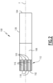
Figure 2 is a simplified cross-sectional view of a variant of the aerosol generating article of the aerosol generating assembly ofFigure 1 , the cross-section being in a plane including an axis of the aerosol generating article. - Before describing the invention, it is to be understood that it is not limited to the details of construction set forth in the following description. It will be apparent to those skilled in the art having the benefit of the present disclosure that the invention is capable of other embodiments and of being practiced or being carried out in various ways.
- As used herein, the term "aerosol generating device" or "device" may include a vaping device to deliver an aerosol to a user, including an aerosol for vaping, by means of a heater element explained in further detail below. The device may be portable. "Portable" may refer to the device being for use when held by a user. The device may be adapted to generate a variable amount of aerosol, e.g. by activating the heater element for a variable amount of time (as opposed to a metered dose of aerosol), which can be controlled by a trigger. The trigger may be user activated, such as a vaping button and/or inhalation sensor. The inhalation sensor may be sensitive to the strength of inhalation as well as the duration of inhalation to enable a variable amount of vapour to be provided (so as to mimic the effect of smoking a conventional combustible smoking article such as a cigarette, cigar or pipe, etc.). The device may include a temperature regulation control to drive the temperature of the heater and/or the heated aerosol generating substance (aerosol pre-cursor) to a specified target temperature and thereafter to maintain the temperature at the target temperature that enables efficient generation of aerosol.
- As used herein, the term "aerosol" may include a suspension of vaporizable material as one or more of: solid particles; liquid droplets; gas. Said suspension may be in a gas including air. Aerosol herein may generally refer to/include a vapour. Aerosol may include one or more components of the vaporizable material.
- As used herein, the term "aerosol generating substrate" or "vaporizable material" may refer to a smokable material which may for example comprise nicotine or tobacco and an aerosol former. Tobacco may take the form of various materials such as shredded tobacco, granulated tobacco, tobacco leaf and/or reconstituted tobacco. Suitable aerosol formers include: a polyol such as sorbitol, glycerol, and glycols like propylene glycol or triethylene glycol; a non-polyol such as monohydric alcohols, acids such as lactic acid, glycerol derivatives, esters such as triacetin, triethylene glycol diacetate, triethyl citrate, glycerin or vegetable glycerin. In some embodiments, the aerosol generating agent may be glycerol, propylene glycol, or a mixture of glycerol and propylene glycol. The substrate may also comprise at least one of a gelling agent, a binding agent, a stabilizing agent, and a humectant.
-
Figure 1 shows anaerosol generating assembly 10 according to the invention. Theaerosol generating assembly 10 comprises anaerosol generating device 20 and anaerosol generating article 100. Theaerosol generating device 20 is intended to operate with theaerosol generating article 100 to generate aerosol. - The
aerosol generating device 20 comprises a device body 22, afirst heater 30, afluid reservoir 32 and asecond heater 34. Thefluid reservoir 32 may be a cartomizer. Advantageously, the cartomizer comprises thesecond heater 34. For instance, theaerosol generating device 20 further comprises an aerosol generatingarticle receiving chamber 42, at least a receivingchamber wall 50, afluid transfer system 62, abattery 74 and acontrol module 78. - As shown on
Figure 1 , the device body 22 extends along a device axis X. The device body 22 further comprises a housing 24 arranged along the device axis X. - The housing 24 comprises an
outer wall 26, making up the external surface of the device body 22. The housing 24 further delimits aninternal space 28 of thedevice 20 for receiving thefirst heater 30, thefluid reservoir 32, thesecond heater 34 and if applicable thecartomizer 38, thefluid transfer system 62, thebattery 74 and thecontrol module 78. Advantageously, theinternal space 28 can receive other various elements designed to carry out different functionalities of thedevice 10. These elements are known as such and will not be disclosed in the further description. - The
first heater 30 is configured for heating an aerosol generating substrate of anaerosol generating part 108 of theaerosol generating article 100. In particular, thefirst heater 30 is configured for heating the receivingchamber 42, especially an aerosol generatingpart receiving portion 49 of the receivingchamber 42. For instance, thefirst heater 30 is an electric heater. Advantageously, thefirst heater 30 is an electric heater film arranged around the receivingchamber 42, in particular around the aerosol generatingpart receiving portion 49. In a variant, thefirst heater 30 is an inductive coil positioned about the receivingchamber 42, advantageously around the aerosol generatingpart receiving portion 49, and capable of heating internal susceptor(s) comprised within theaerosol generating part 108. For example, thefirst heater 30 is adapted to heat the aerosol generating substrate at a temperature of between 250°C and 350°C. For example, thefirst heater 30 is powered by thebattery 74. - The
fluid reservoir 32 is adapted to contain a fluid. For instance, the fluid comprises water. Advantageously, thefluid reservoir 32 is acartomizer 38. For example thecartomizer 38 comprises thesecond heater 34. For example, thecartomizer 38 is removably mounted on the device body 22. In a variant, thefluid reservoir 32 is permanently mounted on the device body 22. In this case, theaerosol generating device 20 comprises a fluid refilling system (not shown) for refilling thefluid reservoir 32 with fluid. - The
second heater 34 is configured for heating the fluid. For example, thesecond heater 34 is embedded in the fluid reservoir 32 (thefluid reservoir 32 is then a cartomizer 38). In a variant, thesecond heater 34 is a part separate from thefluid reservoir 32. In this case, thesecond heater 34 is for instance permanently mounted onto the device body 22. For example, thesecond heater 34 is a resistive heater arranged to heat the fluid conducted from thefluid reservoir 32 for example through a wick or any other porous element. In some other embodiments, thesecond heater 34 can present a magnetic coil adapted to cooperate with a susceptor arranged in contact with the fluid. For instance, thesecond heater 34 is adapted to heat the fluid in a temperature of between 100°C and 350°C (in particular when the fluid comprises water and glycerol). For example, thesecond heater 34 is powered by thebattery 74. - The aerosol generating
article receiving chamber 42 is designed to receive at least a portion of theaerosol generating article 100. As shown on the example ofFigure 1 , the receivingchamber 42 extends along a receiving chamber axis A, which is for example substantially parallel to the device axis X, in particular which coincides with the device axis X. In particular, the receivingchamber 42 is designed to receive the at least one portion of theaerosol generating article 100 so that the receiving chamber axis X coincides with an article axis Y which will be further detailed below. For instance, the receivingchamber 42 has a cross-sectional shape substantially similar to the one of theaerosol generating article 100. Advantageously, as shown onFigure 1 , the receivingchamber 42 extends longitudinally, in particular according to the receiving chamber axis X, between abottom end 44 and afree end 46 opposite thebottom end 44. Thefree end 46 makes up for aninsertion orifice 47 through which theaerosol generating article 100 is intended to be inserted. The receivingchamber 42 comprises at least a heatingelement receiving portion 48 for receiving aheating element 112 of theaerosol generating article 100, which will be further detailed below. For instance, the receivingchamber 42 further comprises at least the aerosol generatingpart receiving portion 49 for receiving theaerosol generating part 108 of theaerosol generating article 100, which will be further detailed below. - For instance, as shown on
Figure 1 , the at least one heatingelement receiving portion 48 is adapted to receive theheating element 112 of theaerosol generating article 100 when theaerosol generating article 100 is received in the receivingportion 42. The at least one heatingelement receiving portion 48 is closer to thebottom end 44 than to thefree end 46. In particular, the at least one heatingelement receiving portion 48 comprises thebottom end 44 of the receivingchamber 42. In the example ofFigure 1 , the receivingchamber 42 comprises a single heatingelement receiving portion 48. - For instance, as shown on
Figure 1 , the at least one aerosol generatingpart receiving portion 49 is adapted to receive theaerosol generating part 108 of theaerosol generating article 100 when theaerosol generating article 100 is received in the receivingportion 42. - The at least one receiving
chamber wall 50 delimits the receivingchamber 42. For example, the at least one receivingchamber wall 50 extends substantially longitudinally along the receiving chamber axis A between aproximal end 52 and adistal end 54. As shown onFigure 1 , thedistal end 54 of thewall 50 delimits theinsertion orifice 47 through which theaerosol generating article 100 is intended to be inserted within the receivingchamber 42. For instance, the at least one receivingchamber wall 50 comprises at least aheat spreading portion 56. - For instance, the at least one
heat spreading portion 56 is configured for transferring the heat generated by the at least one heatingelement receiving portion 48 to the aerosol generatingpart receiving portion 49. In particular, the at least oneheat spreading portion 56 is designed to be put in contact with theheating element 112 and with theaerosol generating part 108, and advantageously is configured for transferring the heat generated by theheating element 112 to theaerosol generating part 108, when theaerosol generating article 100 is received in the receivingchamber 42. For instance, the at least one heat spreading portion presents a thermal conductivity of between 10 W m-1 K-1 and 50 W m-1 K-1. For example, the at least oneheat spreading portion 56 is made up of stainless steel, such as stainless steel 304 or stainless steel 316. - For instance, at least a part 57 of the
outer wall 26 of theaerosol generating device 20, extending around the receivingchamber 42, comprises athermal insulator portion 58 configured for preventing the loss of heat of the aerosol generatingpart receiving portion 58. For instance, the at least onethermal insulator portion 58 presents a thermal conductivity of between 200 W m-1 K-1 and 250 W m-1 K-1. For example, the at least onethermal insulator portion 58 is made up of aluminium. As shown on the example ofFigure 1 , thethermal insulator portion 58 surrounds the receivingchamber 42. In a variant, thethermal insulator portion 58 comprises a vacuum sleeve and/or aerogel. The device may comprise additional structural pieces such as a frame to hold thethermal insulation portion 58 in place and an outer casing (not illustrated). - The
fluid transfer system 62 is configured for transferring the fluid heated by thesecond heater 34 in the at least one heatingelement receiving portion 48 of the receivingchamber 42. - Advantageously, the
battery 74 is configured to power thefirst heater 30 and thesecond heater 34. For example, thebattery 74 is further configured to power thecontrol module 78 and if applicable thefluid transfer system 62. Advantageously, thebattery 74 is further configured to power some or all of the various electronic elements of thedevice 10. - The
control module 78 is configured to control thebattery 74 so that thesecond heater 34 is powered up only when the temperature of theaerosol generating part 108 is below 200°C. For instance, thecontrol module 78 is configured to control thebattery 74 and thefluid transfer system 62 to control the amount of fluid transferred in the at least one heatingelement receiving portion 48. - In reference to
Figure 1 , theaerosol generating article 100 has a cylindrical shape, the base of the corresponding cylinder being for example circular, oval, square, rectangular, triangular, etc. Theaerosol generating article 100 substantially extends along the article axis Y. Theaerosol generating article 100 comprises aproximal end 102 and adistal end 104 opposite theproximal end 102 with regards to the article axis Y. - The
aerosol generating article 100 comprises anaerosol generating part 108 and aheating element 112. Advantageously, theaerosol generating article 100 further comprises amouthpiece portion 126. For example, theheating element 112, theaerosol generating part 108 and if applicable themouthpiece portion 126 are arranged successively along the article axis Y, from theproximal end 102 to thedistal end 104. - The
aerosol generating part 108 comprises an aerosol generating substrate, as defined above. - The
heating element 112 is adapted to heat the aerosol generating substrate by undergoing an exothermic reaction. For instance, theheating element 112 is in contact with theaerosol generating part 108. In particular, theheating element 112 is designed to be put in contact with the fluid heated by thesecond heater 34 of theaerosol generating device 20. When theheating element 112 is put in contact with the heated fluid, this causes an exothermic reaction able to heat the aerosol generating substrate. For example, when theheating element 112 is put in contact with the heated fluid, theheating element 112 undergoes an exothermic reaction heating the aerosol generating substrate comprised in theaerosol generating part 108. For instance, theheating element 112 is made up of a heating material comprising an active component and advantageously a binder mixed with the active component. The active component undergoes the exothermic reaction when in contact with the heated fluid. For example, the active component comprises calcium oxide CaO, calcium chloride CaCl2 or a mix thereof. For instance, the heating material is made up of calcium oxide with a mass proportion between 5% and 95%, calcium chloride with a mass proportion between 10% and 80% or calcium oxide with a mass proportion between 20% and 70% and magnesium oxide with a mass proportion between 30% and 50%. Preferably, the heating material is made up of calcium oxide with a mass proportion of 33%. Preferably again, the heating material is made up of calcium oxide with a mass proportion of 33%, a binder with a mass proportion of 5% and other material(s) suitable for supporting molding with a mass proportion of 62%. Advantageously, the heating element comprises 112 at least atubular channel 116 comprising afirst end 118 designed to be put in fluidic communication with thefluid transfer system 62, in particular when theaerosol generating article 100 is received in the receivingchamber 42, and asecond end 120 fluidically connected to theaerosol generating part 108. As shown on the example ofFigure 1 , theheating element 112 comprises a singletubular channel 116 and a singletubular wall 115 delimiting the singletubular channel 116. As a variant, as shown onFigure 2 , theheating element 112 comprises severaltubular channels 116 and a honeycomb structure 122 delimiting saidtubular channels 116. - The
mouthpiece portion 126 is adapted to be used by a user to draw the aerosol generated by heating of the aerosol generating substrate by theheating element 112.
Claims (15)
- An aerosol generating assembly (10) comprising:- an aerosol generating article (100) comprising an aerosol generating part (108), the aerosol generating part (108) comprising an aerosol generating substrate able to generate aerosol when heated, the aerosol generating article (100) further comprising a heating element (112) adapted to heat the aerosol generating substrate by undergoing an exothermic reaction;- an aerosol generating device (20) comprising a device body (22), a first heater (30) configured for heating the aerosol generating substrate, a reservoir (32) adapted to contain a fluid and a second heater (34) configured for heating the fluid;wherein the heating element (112) is designed to be put in contact with the heated fluid, the contact of the heating element (112) with the heated fluid causing the exothermic reaction, the exothermic reaction being able to heat the aerosol generating substrate to generate aerosol.
- The aerosol generating assembly (10) according to claim 1, wherein the fluid comprises water.
- The aerosol generating assembly (10) according to claim 1 or 2, wherein the heating element (112) is made up of a heating material comprising an active component undergoing the exothermic reaction when in contact with the heated fluid, the active component comprising:- calcium oxide; or- calcium chloride; or- a mix of calcium oxide and magnesium oxide.
- The aerosol generating assembly (10) according to claim 3, wherein the heating material comprises a binder mixed with the active component.
- The aerosol generating assembly (10) according to any one of the preceding claims, wherein the aerosol generating substrate comprises a tobacco substrate.
- The aerosol generating assembly (10) according to any one of the preceding claims, wherein the aerosol generating device (20) comprises a receiving chamber (42) designed to receive at least a portion of the aerosol generating article (100), the receiving chamber (42) comprising at least a heating element receiving portion (48) for receiving the heating element (112);
the aerosol generating device (20) comprising a fluid transfer system (62) configured for transferring the heated fluid in the at least one heating element receiving portion (48) of the receiving chamber (42). - The aerosol generating assembly (10) according to claim 6, wherein the receiving chamber (42) comprises at least an aerosol generating part receiving portion (49) adapted to receive the aerosol generating part (108);
the heating element (112) comprising at least a tubular channel (116) comprising a first end (118) designed to be put in fluidic communication with the fluid transfer system (62) and a second end (120) fluidically connected to the aerosol generating part (108). - The aerosol generating assembly (10) according to claim 7, wherein the heating element (112) comprises a single tubular channel (116), the heating element (112) comprising a single tubular wall (115) delimiting the single tubular channel (116).
- The aerosol generating assembly (10) according to claim 7, wherein the heating element (112) comprises several tubular channels (116), the heating element (112) comprising a honeycomb structure (122) delimiting the tubular channels (116).
- The aerosol generating assembly (10) according to any one of claims 7 to 9, wherein the aerosol generating device (20) comprises at least a receiving chamber wall (50) delimiting the receiving chamber (42), the at least one receiving chamber wall (50) comprising at least a heat spreading portion (56), for example made up of metal, configured for transferring heat generated by the at least one heating element receiving portion (48) to the aerosol generating part receiving portion (49).
- The aerosol generating assembly (10) according to any one of claims 7 to 10, wherein the aerosol generating device (20) comprises an outer wall (26), at least a part (57) of the outer wall (26) extending around the receiving chamber (42) comprising a thermal insulator portion (58) configured for preventing heat loss of the aerosol generating part receiving portion (49).
- The aerosol generating assembly (10) according to any one of claims 7 to 11, wherein the first heater (30) is configured for heating the receiving chamber (42), in particular the aerosol generating part receiving portion (49).
- The aerosol generating assembly (10) according to any one of the preceding claims, wherein the fluid reservoir (32) is removably mounted on the device body (22).
- The aerosol generating assembly (10) according to any one of the preceding claims, wherein the aerosol generating device (20) comprises a cartomizer (38), the cartomizer comprising the second heater (34) and the fluid reservoir (32), the cartomizer (38) being removably mounted on the device body (22).
- The aerosol generating assembly (10) according to any one of the preceding claims, wherein the aerosol generating device (20) comprises:- a battery (74) configured to power the first heater (30) and the second heater (34);- a control module (78) configured to control the battery (74) so that the second heater (34) is powered only when the temperature of the aerosol generating part (108) is below 200°C.
Priority Applications (2)
| Application Number | Priority Date | Filing Date | Title |
|---|---|---|---|
| EP23208977.1A EP4552513A1 (en) | 2023-11-10 | 2023-11-10 | Aerosol generating assembly comprising a heating element capable of exothermic reaction |
| PCT/EP2024/081504 WO2025099155A1 (en) | 2023-11-10 | 2024-11-07 | Aerosol generating assembly comprising a heating element capable of exothermic reaction |
Applications Claiming Priority (1)
| Application Number | Priority Date | Filing Date | Title |
|---|---|---|---|
| EP23208977.1A EP4552513A1 (en) | 2023-11-10 | 2023-11-10 | Aerosol generating assembly comprising a heating element capable of exothermic reaction |
Publications (1)
| Publication Number | Publication Date |
|---|---|
| EP4552513A1 true EP4552513A1 (en) | 2025-05-14 |
Family
ID=88778117
Family Applications (1)
| Application Number | Title | Priority Date | Filing Date |
|---|---|---|---|
| EP23208977.1A Pending EP4552513A1 (en) | 2023-11-10 | 2023-11-10 | Aerosol generating assembly comprising a heating element capable of exothermic reaction |
Country Status (2)
| Country | Link |
|---|---|
| EP (1) | EP4552513A1 (en) |
| WO (1) | WO2025099155A1 (en) |
Citations (4)
| Publication number | Priority date | Publication date | Assignee | Title |
|---|---|---|---|---|
| WO2014045024A2 (en) * | 2012-09-18 | 2014-03-27 | British American Tobacco (Investments) Limited | Heating smokeable material |
| US9046278B2 (en) * | 2008-06-27 | 2015-06-02 | Olig Ag | Smoke-free cigarette |
| US11272578B2 (en) * | 2016-11-18 | 2022-03-08 | Philip Morris Products S.A. | Heating assembly, aerosol-generating device and a method for heating an aerosol-forming substrate |
| US20220346456A1 (en) * | 2020-01-30 | 2022-11-03 | Nerudia Limited | Aerosol delivery apparatus |
-
2023
- 2023-11-10 EP EP23208977.1A patent/EP4552513A1/en active Pending
-
2024
- 2024-11-07 WO PCT/EP2024/081504 patent/WO2025099155A1/en active Pending
Patent Citations (4)
| Publication number | Priority date | Publication date | Assignee | Title |
|---|---|---|---|---|
| US9046278B2 (en) * | 2008-06-27 | 2015-06-02 | Olig Ag | Smoke-free cigarette |
| WO2014045024A2 (en) * | 2012-09-18 | 2014-03-27 | British American Tobacco (Investments) Limited | Heating smokeable material |
| US11272578B2 (en) * | 2016-11-18 | 2022-03-08 | Philip Morris Products S.A. | Heating assembly, aerosol-generating device and a method for heating an aerosol-forming substrate |
| US20220346456A1 (en) * | 2020-01-30 | 2022-11-03 | Nerudia Limited | Aerosol delivery apparatus |
Also Published As
| Publication number | Publication date |
|---|---|
| WO2025099155A1 (en) | 2025-05-15 |
Similar Documents
| Publication | Publication Date | Title |
|---|---|---|
| EP3086672B1 (en) | Smoking article with a valve | |
| JPH03112477A (en) | Requisite article for smoker | |
| EP2644043A1 (en) | Heatable smoking article with improved wrapper | |
| CN114521112A (en) | Aerosol-generating system | |
| JPS63192372A (en) | aerosol delivery article | |
| US20240277053A1 (en) | Flat Tobacco Article Comprising at Least Two Layers and Aerosol Generating Device with Such an Article | |
| KR20240053047A (en) | Aerosol-generating device and associated aerosol-generating assembly comprising a heating chamber of planar shape | |
| WO2022207743A1 (en) | Aerosol generation device with comb-shaped electrodes | |
| JP2025535902A (en) | Tobacco articles with resistive layers and related aerosol-generating assemblies | |
| WO2025099155A1 (en) | Aerosol generating assembly comprising a heating element capable of exothermic reaction | |
| EP4503987B1 (en) | Aerosol generating device comprising two heating plates and associated method of controlling | |
| US20240268452A1 (en) | Flat Tobacco Article Comprising at Least Two Layers and Aerosol Generating Device with Such an Article | |
| US20240065314A1 (en) | Filter for Smoking Article | |
| JP2026504490A (en) | Aerosol generating device with thermal break and related aerosol generating assembly - Patent Application 20070122997 | |
| EP4604769A1 (en) | Aerosol generating assembly | |
| WO2024235856A1 (en) | A cleaning tool for cleaning an aerosol generating device and an aerosol generating system comprising a cleaning tool | |
| WO2025003301A1 (en) | Aerosol generating device comprising a heating cup | |
| WO2024153758A1 (en) | Aerosol generating device configured to operate with an aerosol generating substrate | |
| EP4651744A1 (en) | Aerosol generating device comprising two heating plates | |
| JP2026507698A (en) | Aerosol generating device including a grip portion and related aerosol generating assembly | |
| WO2024227799A1 (en) | Aerosol generating device comprising a 3d printed ceramic cup and associated method for producing | |
| WO2023194533A1 (en) | Aerosol generating device comprising a heating plate comprising a ceramic part and a metal part and associated method for controlling | |
| WO2024003365A1 (en) | Aerosol generating assembly comprising a heat conducting element | |
| WO2024126663A1 (en) | A tobacco article comprising an inductively heatable susceptor, and assembly comprising such an article | |
| JP2026507172A (en) | Aerosol generating device including a heated chamber configured to at least partially contain an aerosol product - Patent Application 20070122997 |
Legal Events
| Date | Code | Title | Description |
|---|---|---|---|
| PUAI | Public reference made under article 153(3) epc to a published international application that has entered the european phase |
Free format text: ORIGINAL CODE: 0009012 |
|
| STAA | Information on the status of an ep patent application or granted ep patent |
Free format text: STATUS: THE APPLICATION HAS BEEN PUBLISHED |
|
| AK | Designated contracting states |
Kind code of ref document: A1 Designated state(s): AL AT BE BG CH CY CZ DE DK EE ES FI FR GB GR HR HU IE IS IT LI LT LU LV MC ME MK MT NL NO PL PT RO RS SE SI SK SM TR |
|
| STAA | Information on the status of an ep patent application or granted ep patent |
Free format text: STATUS: REQUEST FOR EXAMINATION WAS MADE |
|
| GRAP | Despatch of communication of intention to grant a patent |
Free format text: ORIGINAL CODE: EPIDOSNIGR1 |
|
| STAA | Information on the status of an ep patent application or granted ep patent |
Free format text: STATUS: GRANT OF PATENT IS INTENDED |
|
| 17P | Request for examination filed |
Effective date: 20251029 |
|
| INTG | Intention to grant announced |
Effective date: 20251128 |