EP4550955A1 - Cable cover and constant-temperature unit provided with same - Google Patents
Cable cover and constant-temperature unit provided with same Download PDFInfo
- Publication number
- EP4550955A1 EP4550955A1 EP23871414.1A EP23871414A EP4550955A1 EP 4550955 A1 EP4550955 A1 EP 4550955A1 EP 23871414 A EP23871414 A EP 23871414A EP 4550955 A1 EP4550955 A1 EP 4550955A1
- Authority
- EP
- European Patent Office
- Prior art keywords
- cable
- holding
- cable cover
- holding member
- cover according
- Prior art date
- Legal status (The legal status is an assumption and is not a legal conclusion. Google has not performed a legal analysis and makes no representation as to the accuracy of the status listed.)
- Pending
Links
Images





Classifications
-
- H—ELECTRICITY
- H02—GENERATION; CONVERSION OR DISTRIBUTION OF ELECTRIC POWER
- H02G—INSTALLATION OF ELECTRIC CABLES OR LINES, OR OF COMBINED OPTICAL AND ELECTRIC CABLES OR LINES
- H02G3/00—Installations of electric cables or lines or protective tubing therefor in or on buildings, equivalent structures or vehicles
- H02G3/22—Installations of cables or lines through walls, floors or ceilings, e.g. into buildings
-
- H—ELECTRICITY
- H05—ELECTRIC TECHNIQUES NOT OTHERWISE PROVIDED FOR
- H05B—ELECTRIC HEATING; ELECTRIC LIGHT SOURCES NOT OTHERWISE PROVIDED FOR; CIRCUIT ARRANGEMENTS FOR ELECTRIC LIGHT SOURCES, IN GENERAL
- H05B3/00—Ohmic-resistance heating
- H05B3/40—Heating elements having the shape of rods or tubes
-
- C—CHEMISTRY; METALLURGY
- C12—BIOCHEMISTRY; BEER; SPIRITS; WINE; VINEGAR; MICROBIOLOGY; ENZYMOLOGY; MUTATION OR GENETIC ENGINEERING
- C12M—APPARATUS FOR ENZYMOLOGY OR MICROBIOLOGY; APPARATUS FOR CULTURING MICROORGANISMS FOR PRODUCING BIOMASS, FOR GROWING CELLS OR FOR OBTAINING FERMENTATION OR METABOLIC PRODUCTS, i.e. BIOREACTORS OR FERMENTERS
- C12M41/00—Means for regulation, monitoring, measurement or control, e.g. flow regulation
- C12M41/12—Means for regulation, monitoring, measurement or control, e.g. flow regulation of temperature
- C12M41/14—Incubators; Climatic chambers
-
- H—ELECTRICITY
- H02—GENERATION; CONVERSION OR DISTRIBUTION OF ELECTRIC POWER
- H02G—INSTALLATION OF ELECTRIC CABLES OR LINES, OR OF COMBINED OPTICAL AND ELECTRIC CABLES OR LINES
- H02G15/00—Cable fittings
- H02G15/013—Sealing means for cable inlets
-
- H—ELECTRICITY
- H02—GENERATION; CONVERSION OR DISTRIBUTION OF ELECTRIC POWER
- H02G—INSTALLATION OF ELECTRIC CABLES OR LINES, OR OF COMBINED OPTICAL AND ELECTRIC CABLES OR LINES
- H02G3/00—Installations of electric cables or lines or protective tubing therefor in or on buildings, equivalent structures or vehicles
- H02G3/02—Details
- H02G3/06—Joints for connecting lengths of protective tubing or channels, to each other or to casings, e.g. to distribution boxes; Ensuring electrical continuity in the joint
- H02G3/0616—Joints for connecting tubing to casing
- H02G3/0625—Joints for connecting tubing to casing with means for preventing disengagement of conductors
- H02G3/0675—Joints for connecting tubing to casing with means for preventing disengagement of conductors with bolts operating in a direction parallel to the conductors
Definitions
- the present invention relates to a cable cover that fixes a cable that goes from the inside to the outside through an opening provided in the wall of a constant-temperature unit, to the wall surface of the constant-temperature unit, as well as a constant-temperature unit equipped with this cable cover, for example.
- Culture devices have been widely used in recent years for culturing cells, microorganisms, and so forth. These culture devices are provided with a heater or the like to create a high-temperature and high-humidity environment in the culture chamber.
- Patent Literature 1 discloses a cover that is attached to a wall when a cable or the like is being passed through a constant-temperature unit such as a working device or a storage device, as well as a constant-temperature unit in which this cover is used.
- This cover is used in a constant-temperature unit having an internal chamber that is surrounded by a plurality of walls, at least one of which has a hole in it, and a temperature and humidity control unit that controls the temperature and humidity in the internal chamber, and this cover is attached so as to cover up the hole in the wall, with a space between the wall and the cover, and has one or more hole portions that are used to pass a string-like object extending from the outside of the internal chamber to the inside through the hole, and further has a surrounding portion that makes sealing contact with the wall, a contact portion that makes sealing contact with the string-like object in the hole, and a seal body that makes sealing contact with the hole, and the string-like object is passed through the seal body while preserving the sealed state, and part of the string-like object is held within the space.
- Patent Literature 1 JP-A 2009-178070 ( Japanese Patent No. 5,017,133 )
- a heater is built into the inner wall of the constant-temperature unit, and the temperature inside the storage chamber can be kept constant by the heater and thermal insulating material.
- the interior of the cable storage section and a part of the cable stored inside the cable storage section are heated by thermal conduction from the heater, which prevents condensation on the cover.
- the cable cover according to the first invention is a cable cover that fixes, in an installation hole provided in a wall surface of a constant-temperature unit, a cable coming out of the internal space, through the installation hole, and into the external space, the cable cover including a holding member, a first sleeve member, and a heating unit.
- the holding member holds the cable.
- the substantially cylindrical first sleeve member is disposed around the outer periphery of the holding member.
- the heating unit is disposed on the first sleeve member and applies heat to the cable held by the holding member via the first sleeve member.
- heat is applied from the heating unit disposed on the first sleeve member to the cable that goes from the internal space to the external space through the installation hole provided in the wall of the constant-temperature unit and is held by the holding member, thereby heating part of the cable that is fixed in the installation hole provided in the wall of the constant-temperature unit.
- the constant-temperature unit is, for example, a box-shaped device such as an incubator that creates a high-temperature and high-humidity environment in the internal space of the housing and controls the internal space to maintain a constant environment.
- the first sleeve member is, for example, a component made of a metal having high thermal conductivity, such as aluminum, and is provided with a heating unit such as a heater on its outer peripheral surface.
- the heating unit is, for example, a sheet-shaped heater, and is switched between heating and non-heating states by turning the supply of power on or off.
- the cable cover according to the second aspect of the present invention is a cable cover that fixes, in an installation hole provided in a wall surface of a constant-temperature unit, a cable coming out of the internal space, through the installation hole, and into the external space, the cable cover including a first holding member, a second holding member, and a heating unit.
- the first holding member holds the cable.
- the second holding member is disposed so as to come into contact with the first holding member each other in the extension direction of the cable.
- the heating unit is disposed on the first holding member and applies heat to the cable held by the first holding member via the first holding member.
- heat is applied from a heating unit disposed on the first holding member to a cable that goes from the internal space to the external space through an installation hole provided in the wall of the constant-temperature unit, and is held by the holding member, thereby heating part of the cable that is fixed in the installation hole provided in the wall of the constant-temperature unit.
- the constant-temperature unit is, for example, a box-shaped device such as an incubator that produces an environment of high temperature and humidity in the internal space of the housing and controls the internal space to maintain a constant environment.
- the first holding member is, for example, a component made of a metal having high thermal conductivity, such as aluminum, and is provided with a heating unit such as a heater.
- the heating unit is, for example, a cylindrical cartridge-type heater, and switching between heating and non-heating states is accomplished by turning the power supply on or off.
- the cable cover according to the third invention is a cable cover that fixes, in an installation hole provided in a wall surface of a constant-temperature unit, a cable coming out of the internal space, through the installation hole, and into the external space, wherein a holding member holds the cable.
- a substantially cylindrical sleeve member is disposed around the outer periphery of the holding member and has a first threaded portion formed on the outer peripheral surface of the sleeve member along the lengthwise direction of the cable.
- a fixing member has a substantially annular main body part and a second threaded portion formed on the inner peripheral side of the main body part and meshing with the first threaded portion, and is fixed at a position corresponding to the length of the installation hole in a state in which the second threaded portion is meshed with the first threaded portion.
- the cable that has been passed from the internal space to the external space through the installation hole provided in the wall of the constant-temperature unit and is held by the holding member is attached in the installation hole provided in the wall of the constant-temperature unit, the cable is fixed using a fixing member that meshes with a first threaded portion formed on the outer peripheral surface of the sleeve member along the lengthwise direction of the cable.
- the fixing member is fastened at a position on the first threaded portion according to the length of the installation hole.
- the cable cover according to the fourth invention is the cable cover according to the first invention, further equipped with a substantially cylindrical second sleeve member that is attached so as to cover the outer periphery of the first sleeve member and the heating unit.
- the cable cover according to the fifth invention is the cable cover according to the fourth invention, wherein the second sleeve member has a first threaded portion that is formed on the substantially cylindrical outer peripheral surface along the lengthwise direction of the cable.
- the cable cover is further equipped with a fixing member that has a substantially annular main body part and a second threaded portion formed on the inner peripheral side of the main body part and meshing with the first threaded portion, and that is fixed at a position corresponding to the length of the installation hole in a state in which the second threaded portion is meshed with the first threaded portion.
- the cable cover according to the sixth invention is the cable cover according to the fourth invention, wherein the second sleeve member has a first end on the outdoor side of the constant-temperature unit, and a second end on the indoor side.
- the cable cover is further equipped with an intermediate member that is disposed on the side of the second end of the second sleeve member and has substantially the same outside diameter as the second sleeve member, and a cap member that is attached so as to cover the second end of the second sleeve member and the outer peripheral surface of the intermediate member.
- the side of the second end of the second sleeve member can be covered by attaching the cap member so as to cover the second end on the indoor side of the second sleeve member and the intermediate member disposed near the second end.
- the cable cover according to the seventh invention is the cable cover according to the sixth invention, wherein mounting of the cap member causes the intermediate member to be deformed, forming a waterproofing mechanism in the installation hole.
- a waterproofing mechanism can be formed near the cable installed in the installation hole by deforming the intermediate member when the cap member is mounted.
- the cable cover according to the eighth invention is The cable cover according to the sixth or seventh invention, further equipped with a sealing member that is mounted to the outer peripheral surface of the cap member, is elastic, and is inserted into the installation hole to seal off the internal space.
- the cable cover according to the ninth invention is the cable cover according to the first or third invention, wherein the holding member has a plurality of holding portions that hold a plurality of the cables.
- the cable cover according to the eleventh invention is the cable cover according to the first or third invention, wherein the holding member is elastic.
- the cable can be held while being appropriately deformed according to the shape of the cable by holding the cable with an elastic holding member. This prevents gaps from occurring near the cable and maintains the airtightness of the internal space of the constant-temperature unit.
- the cable cover according to the twelfth invention is The cable cover according to the eleventh invention, wherein the holding member has a press-fit portion that makes contact with the inner peripheral surface of the installation hole when installed in the installation hole, and is held by elastic deformation.
- the cable cover according to the thirteenth invention is The cable cover according to the eleventh invention, wherein the holding member has a holding portion that holds the cable, and a cut portion that is provided in the outer peripheral surface thereof and that elastically deforms when the cable is held by the holding portion, thereby moving the cable to the holding portion.
- the cable can be stably held inside the holding member by elastically deforming the cut portion provided on the outer peripheral surface of the holding member and inserting the cable into the holding portion.
- the cable cover according to the fourteenth invention is The cable cover according to the second invention, wherein the first holding member has a substantially cylindrical insertion hole provided in the center thereof, and the heating unit is inserted into the insertion hole.
- heat coming off the heating unit can be transferred to the cable held by the first holding member by inserting the heating unit into the insertion hole provided in the center of the first holding member.
- the cable cover according to the fifteenth invention is the cable cover according to the fourteenth invention, wherein the first holding member has a holding portion provided on the outer peripheral side of the insertion hole, and the cable is held in this holding portion.
- the cable cover according to the sixteenth invention is the cable cover according to the fifteenth invention, wherein the first holding member has a plurality of the holding portions, and the plurality of holding portions are recesses into which the cables are fitted from the outer peripheral side of the first holding member.
- the cable cover according to the seventeenth invention is the cable cover according to the second invention, wherein the second holding member is formed by a substantially cylindrical elastic member.
- the cable cover according to the eighteenth invention is the cable cover according to the seventeenth invention, wherein the second holding member has a holding portion that holds the cable, and a cut portion that is provided on the outer peripheral surface of the holding portion and elastically deforms when the cable is held by this holding portion, thereby moving the cable to the holding portion.
- the cable can be stably held inside the second holding member by elastically deforming the cut portioned portion provided on the outer peripheral surface of the second holding member and inserting the cable into the holding portion.
- the cable cover according to the nineteenth invention is the cable cover according to the seventeenth invention, wherein the second holding member has a press-fit portion that makes contact with the inner peripheral surface of the installation hole when installed in the installation hole and is held by elastic deformation.
- the cable cover can be easily fixed to the installation hole by utilizing the elasticity of the second holding member to press-fit the second holding member so that its outer peripheral surface makes contact with the inner peripheral surface of the installation hole.
- the cable cover according to the twentieth invention is the cable cover according to the second invention, wherein the first holding member is formed from a metal material having high thermal conductivity.
- the first holding member is made of a metallic material such as aluminum, for example, the heat coming off the heating unit can be efficiently transferred to the cable.
- the constant-temperature unit according to the twenty-first invention is equipped with the cable cover according to any of the first to third inventions, an attachment fixture that is provided to an installation hole to which the cable cover is attached, and a housing that includes the wall surface provided with the installation hole to which the mounting fixture is attached.
- a constant-temperature unit can be provided with which condensation can be more effectively prevented from occurring near the opening in a cable cover that fixes a cable coming from the inside to the outside through an opening provided in the wall of the constant-temperature unit.
- the cable cover of the present invention in a cable cover that secures a cable pulled from the inside to the outside through an opening provided in the wall of a constant-temperature unit, the occurrence of condensation near the opening can be more effectively prevented.
- a cable cover 10 according to an embodiment of the present invention, and an incubator (constant-temperature unit) 30 including the same will now be described with reference to Figs. 1 to 16c .
- the cable cover 10 in this embodiment fixes a cable C (see Fig. 7 , etc.) that is passed from the internal space S2 to the external space S1 through a measurement hole (installation hole) 20 provided on the rear surface (wall surface) 32 of an incubator (constant-temperature unit) 30.
- a measurement device (not shown) that makes various measurements of cell culture, etc., is placed in an internal space S2 formed in a housing 31, and the cable C for supplying power to the measurement device or transmitting and receiving various kinds of signal is passed through to the external space S1.
- the constant-temperature unit 30 is set such that the internal space S2 has an environment of high temperature and humidity environment (such as 37 degrees and 80%) in order to maintain the environment of the cells to be cultured. Accordingly, when the temperature in the external space S1 is low (such as 25 degrees or lower), condensation may occur near the measurement hole 20 on the cable C passed through from the internal space S2 to the external space S1, and on the inner wall near the measurement hole 20 in the internal space S2.
- the anti-condensation structure provided by the cable cover 10 of this embodiment will be described in detail at a later point.
- the constant-temperature unit 30 has a measurement hole 20 provided in a recess 32a provided on the rear surface 32 in order to pass the cable C from the internal space S2 of the housing 31 into the external space S1.
- the measurement hole 20 is a cylindrical member to which the cable cover 10 holding the cable C is fixed, and is provided in a through-hole that goes through the rear surface 32. As shown in Fig. 3 , the measurement hole 20 has a substantially cylindrical main body part 20a and a flange portion 20b.
- the substantially cylindrical main body part 20a is inserted from the external space S1 side along the inner peripheral surface of a through-hole formed in the rear surface 32, and then fixed.
- the flange portion 20b is formed on the external space S1 side of the substantially cylindrical main body part 20a, and is provided so as to protrude outward in the radial direction from the outer peripheral surface at the end of the main body part 20a on the external space S1 side.
- the flange portion 20b is fixed so as to make contact with the surface on the external space S1 side of the rear surface 32.
- the cable cover 10 holding the cable C (see Fig. 7 , etc.) is attached to the measurement hole 20.
- the cable cover 10 includes a grommet (holding member) 11, a core sleeve (first sleeve member, sleeve member) 12, a heater (heating unit) 13, an outer sleeve (second sleeve member, sleeve member) 14, an intermediate member 15, a distal end cap (cap member) 16, a sealing member 17, and a nut member (fixing member) 18.
- the grommet (holding member) 11 is, for example, a member made of silicone rubber, and envelops the cable C while elastically deforming, and holds the outer peripheral portion of the cable C.
- the grommet 11 has a main body part 11a that constitutes the center portion of the cable cover 10, and a holding portion 11b that holds four cables C (see Fig. 7 , etc.).
- the main body part 11a is a substantially cylindrical member and has grooves for holding the four cables C in its outer peripheral surface.
- the holding portions 11b are provided at the end on the internal space S2 side of the main body part 11a, and hold the cables C that are passed through a cut portion 11ba (see Figs. 6 and 7 ) while being elastically deformed.
- the holding portions 11b for holding the four cables C those that are not holding a cable C allow the internal space S2 of the constant-temperature unit 30 to communicate with the external space S1, so in this embodiment, the holding portions 11b are blocked off with plugs (blocking members) 11c made of silicone rubber, as shown in Fig. 5 .
- the substantially cylindrical core sleeve (first sleeve member, sleeve member) 12 is, for example, a substantially cylindrical member made of aluminum, which has high thermal conductivity, and the grommet 11 is inserted and attached from the distal end thereof.
- a sheet-shaped heater 13 is wrapped around the outer peripheral surface of the core sleeve 12.
- the main body part 12a is a substantially cylindrical member, and is provided with a flange portion 12b at the end on the external space S1 side.
- the flange portion 12b protrudes outward in the radial direction from the outer peripheral surface of the main body part 12a, and includes a portion that where a heater wire 13a (see Figs. 3 and 4b ) of the heater 13 (discussed below) is passed through to the outside.
- a cut portion 12c is formed so as to split the outer peripheral surface of the substantially cylindrical main body part 12a in two along the axial direction.
- the heater (heating unit) 13 is disposed on the outer peripheral surface of the main body part 12a of the core sleeve 12, as shown in Fig. 6 , in order to heat the portion of the cables C near the measurement hole 20, and applies heat to the cables C held in the grommet 11 enveloped by the core sleeve 12.
- the heater wire 13a is connected to the heater 13 provided on the outer peripheral surface of the main body part 12a of the core sleeve 12 in order to supply power to the heater 13, and is passed through to the external space S1. If the temperature of the outer surface of a cable C to be heated exceeds a specific temperature setting, for example, the supply of power from the heater wire 13a to the heater 13 is halted, and once the temperature falls below the set temperature, the supply of power to the heater 13 is started.
- a specific temperature setting for example, the supply of power from the heater wire 13a to the heater 13 is halted, and once the temperature falls below the set temperature, the supply of power to the heater 13 is started.
- the outer sleeve (second sleeve member, sleeve member) 14 is a substantially cylindrical member made of resin such as PC ( polycarbonate ), and is attached so as to cover the outer periphery of the core sleeve 12 and the heater 13. As shown in Fig. 6 , the outer sleeve 14 has a main body part 14a, a large diameter portion 14b, a small diameter portion 14c, threaded portions 14ca and 14cb, and a cut portion 14d.
- the main body part 14a is configured by linking two substantially cylindrical members (the large diameter portion 14b and the small diameter portion 14c) having different outside diameters.
- the large diameter portion 14b is a substantially cylindrical member on the side of the main body part 14a that has a larger outside diameter, and envelops the flange portion 12b of the core sleeve 12.
- the small diameter portion 14c is a substantially cylindrical member on the side of the main body part 14a that has a smaller outside diameter, and envelops the heater 13 disposed on the outer peripheral surface of the main body part 12a of the core sleeve 12.
- the threaded portion (first threaded portion) 14ca is formed along the lengthwise direction of the cables C on the outer peripheral surface in the middle part of the substantially cylindrical main body part 14a, and a nut member 18 (discussed below) is threaded onto the threaded portion 14ca.
- the threaded portion 14cb is formed on the outer peripheral surface of the end portion on the internal space S2 side of the main body part 14a, and is fixed in a state in which a threaded portion 16c of the distal end cap 16 (discussed below) has been threaded on.
- the cut portion 14d is formed so as to split the outer peripheral surface of the substantially cylindrical main body part 14a in two along the axial direction.
- the core sleeve 12 is then inserted from the distal end of the outer sleeve 14 toward the inner peripheral surface side in a state in which the cut portion 14d is open.
- the intermediate member 15 is a substantially cylindrical member that is disposed on the side of the outer sleeve 14 where the end (second end) on the internal space S2 side is located, and has substantially the same outside diameter as the outer sleeve 14.
- the intermediate member 15 has a main body part 15a and slits 15b.
- the main body part 15a is a substantially cylindrical member made of PTFE (polytetrafluoroethylene) and is enveloped on the inner peripheral surface side of the distal end cap 16.
- PTFE polytetrafluoroethylene
- a plurality of the slits 15b are formed around the outer peripheral surface of the main body part 15a and running in the lengthwise direction of the cables C.
- This deformation of the intermediate member 15 creates a waterproof structure near the measurement hole 20.
- the distal end cap (cap member) 16 is a substantially cylindrical member made of a resin such as PC (polycarbonate) and, as shown in Fig. 6 , is attached so as to cover the end on the internal space S2 side of the outer sleeve 14 and the outer peripheral surface of the intermediate member 15.
- the distal end cap 16 has a main body part 16a, a recess 16b, a threaded portion 16c, and a tapered portion 16d.
- the main body part 16a is a substantially cylindrical member.
- the recess 16b is a groove into which a sealing member 17 (discussed below) fits, and is provided near the approximate center of the main body part 16a.
- the threaded portion 16c meshes with the above-mentioned threaded portion 14cb of the outer sleeve 14. This allows the distal end cap 16 to be fixed to the end on the internal space S2 side of the outer sleeve 14.
- the tapered portion 16d is provided on the inner peripheral surface side of the substantially cylindrical main body part 16a, and as shown in Fig. 16A , is formed so that its inside diameter decreases toward the internal space S2 side.
- a waterproofing mechanism can be formed in the measurement hole 20 by the elastic deformation of the main body part 15a of the intermediate member 15 as the distal end cap 16 is mounted to the distal end of the outer sleeve 14.
- the sealing member 17 is, for example, a substantially annular member made of silicone rubber, which is mounted to the outer peripheral surface of the distal end cap 16 and has an elastic main body part 17a and a cut portion 17b.
- the sealing member 17 is inserted into the measurement hole 20 to seal the space on the indoor side from the outdoor side.
- the main body part 17a is a substantially annular elastically deformable member, and is attached to the recess 16b of the distal end cap 16 in a state in which the cut portion 17b has been opened.
- the cut portion 17b is formed so as to split the outer peripheral surface of the substantially annular main body part 17a in two along the axial direction. Consequently, the main body part 17a can be attached to the recess 16b of the distal end cap 16 by opening the cut portion 17b while elastically deforming the main body part 17a.
- the nut member 18 is a fastening member made of polycarbonate (PC) or another such resin, and as shown in Fig. 6 , has a substantially annular main body part 18a and a threaded portion (second threaded portion) 18b that is formed on the inner peripheral side of the main body part 18a and meshed with the threaded portion 14ca on the outer sleeve 14.
- the nut member 18 is fixed at a position according to the length of the measurement hole 20 in a state in which the threaded portion 18b is meshed with the threaded portion 14ca on the outer sleeve 14 side.
- the threaded portion 18b of the nut member 18 meshes with the threaded portion 14ca formed near the center of the main body part 14a of the outer sleeve 14, and therefore does not mesh with the threaded portion 14cb formed at the end on the internal space S2 side.
- the nut member 18 can be inserted into the threaded portion 14ca side without meshing with the threaded portion 18b of the nut member 18.
- the grommet 11 On the external space S1 side of the cables C passed from the internal space S2 of the constant-temperature unit 30 to the external space S1, the grommet 11 is attached so as to hold the outer peripheral surface of the cables C, as shown in Fig. 7 .
- the main body part 11a of the grommet 11 is elastically deformed, and the cut portions 11ba formed in the four holding portions 11b are opened so that the cables C can be held in the holding portions 11b.
- a plug 11c is inserted into any holding portion 11b that does not hold a cable C, as shown in Fig. 7 .
- sleeve members core sleeve 12 and outer sleeve 14
- the grommet 11 holding the cables C covers the outer periphery.
- the grommet 11 is inserted from the distal end of the core sleeve 12 and is held on the inner peripheral surface side.
- the nut member 18 is attached so as to mesh with the threaded portion 14ca provided on the outer periphery of the outer sleeve 14.
- the nut member 18 turns and moves to the end on the external space S1 side in a state of being meshed with the threaded portion 14ca.
- the distal end cap 16 is attached to the end of the small diameter portion 14c in the main body part 14a of the outer sleeve 14.
- the distal end cap 16 is fixed when the threaded portion 16c formed on its inner peripheral surface meshes with the threaded portion 14cb formed on the end of the small diameter portion 14c.
- the cut portion 17b of the main body part 17a is opened from the internal space S2 side and the sealing member 17 is attached in the recess 16b of the main body part 16a of the distal end cap 16.
- the nut member 18 is turned to move over the threaded portion 14ca of the outer sleeve 14 to the internal space S2 side as shown in Fig. 14 , and the nut member 18 is fixed at a position where it presses against the flange portion 20b of the measurement hole 20.
- the cable cover 10 is fixed to the measurement hole 20 attached to the rear surface 32 of the housing 31 of the constant-temperature unit 30.
- the length of the measurement hole 20 may vary from one device to the next.
- the cable cover 10 of this embodiment can be attached to both of the measurement holes 20 and 120, which have different lengths, by changing the fixing position of the nut member 18 that meshes with the threaded portion 14ca provided on the outer peripheral surface of the outer sleeve 14.
- the cable cover 10 is fixed when the nut member 18 moves a short distance to the position where it hits the flange portion 120b for a long measurement hole 120.
- the cable cover 10 of this embodiment can be attached to either of the measurement holes 20 and 120 attached to the constant-temperature unit 30 or other such constant-temperature unit, even though the measurement holes 20 and 120 have different lengths.
- FIG. 17 to 19 show a state in which the cables C are not held in the cable cover 110.
- the cable cover 110 of this embodiment fixes cables C (see Fig. 7 , etc.) that are passed from the internal space S2 to the external space S1 through a measurement hole 20 attached to the constant-temperature unit 30 or other such constant-temperature unit.
- the cable cover 110 has a grommet (holding member) 111, a core sleeve (first sleeve member) 112, a sheet heater (heating unit) 113, and an outer sleeve (second sleeve member) 114.
- the grommet (holding member) 111 is, for example, a member made of silicone rubber, which envelops the cables C while being elastically deformed, and holds the outer peripheral portion of the cables C.
- the grommet 111 has a main body part 111a that constitutes the center portion of the cable cover 110, a cylindrical portion 111b that is linked to the main body part 111a and has a larger outside diameter than the main body part 111a, and a holding portion 111c that holds four cables C (see Fig. 7 , etc.).
- the grommet 111 has cut portions 111ba that are provided on the outer peripheral surface of the cylindrical portion 111b and that elastically deform when the cables C are held by the holding portion 111c, thereby moving the cables C to the holding portion 111c.
- any holding portion 111c that does not hold a cable C is blocked off with a resin plug (blocking member) 111d. This makes it less likely that the internal space S2 of the constant-temperature unit 30 and the external space S1 will communicate with each other via any holding portions 111c that do not hold cables C.
- the grommet 111 has a press-fit portion 111e that hits the inner peripheral surface of the measurement hole 20 when installed in the measurement hole 20, and is held in place by the elastic deformation of the cylindrical portion 111b.
- the core sleeve (first sleeve member) 112 is a member that is made by cutting aluminum, for example, and is disposed on the outer peripheral side of the grommet 111, and as shown in Fig. 18 , has a substantially cylindrical main body part 112a and a cut portion 112ab provided along the lengthwise direction of the main body part 112a.
- the cut portion 112ab is a gap formed along the lengthwise direction so as to split the substantially cylindrical main body part 112a in the peripheral direction.
- the sheet heater (heating unit) 113 is disposed on the outer peripheral surface of the main body part 112a of the core sleeve 112 as shown in Fig. 19 in order to heat a part of the cables C near the measurement hole 20, and applies heat to the cables C held in the grommet 111 enveloped by the core sleeve 112.
- the sheet heater 113 has a main body part 113a, a retainer 113b, and a heater wire 113c.
- the main body part 113a is a sheet-like member and has a connection portion 113aa that is connected to the heater wire 113c, and a cut portion 113ab that is formed along the lengthwise direction so as to split the substantially cylindrical main body part 113a in the peripheral direction.
- the retainer 113b is a member that latches the heater wire 113c so that this wire will not come loose, and is mounted on the external space S1 side of the main body part 113a.
- the heater wire 113c is connected to the connection portion 113aa of the main body 113a, is provided in order to supply power to the sheet heater 113, and is passed out to the external space S1. If the temperature of the outer surface of the cables C to be heated exceeds a specific temperature setting, for example, the supply of power from the heater wire 113c to the sheet heater 113 is halted, and if the temperature falls below the temperature setting, the supply of power to the sheet heater 113 is started.
- the outer sleeve (second sleeve member) 114 is formed, for example, by cutting a resin, and is a member that is disposed on the outer peripheral surface side of the core sleeve 112 and the sheet heater 113. As shown in Fig. 18 , the outer sleeve 114 has a substantially cylindrical main body part 114a, an arc portion 114aa that is provided at the end of the main body part 114a on the external space S1 side, and a cut portion 114ab that is provided along the lengthwise direction of the main body part 114a.
- the arc portion 114aa is provided at the end of the main body part 114a on the external space S1 side, is formed so that the end of the main body part 114a is split in the peripheral direction, and is a substantially arc-shaped portion when viewed from the external space S1 side.
- the connecting portion 113aa is disposed so as to be in contact with the portion that is split in the peripheral direction where the arc portion 114aa is provided, as shown in Figs. 17 and 19 .
- the cut portion 114ab is formed along the lengthwise direction so as to split the substantially cylindrical main body part 114a in the peripheral direction.
- the grommet 111 has the press-fit portion 111e that hits the inner surface of the measurement hole 20 when installed in the measurement hole 20 and is held in place by the elastic deformation of the cylindrical portion 111b (see Fig. 19 ).
- the sheet heater 113 is disposed around the outer peripheral surface of the main body part 112a of the core sleeve 112, and applies heat to the cables C held in the grommet 111 contained enveloped by the core sleeve 112.
- FIG. 20 and 21 show the cable cover 210 in a state of not holding any cables C
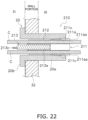
- Fig. 22 shows the cable cover 210 in a state of holding the cables C.
- the cable cover 210 of this embodiment just as with the cable covers 10 and 110 of the above Embodiments 1 and 2, fixes cables C (see Fig. 22 , etc.) that are passed from the internal space S2 to the external space S1 through a measurement hole 20 attached to an incubator 30 or other such constant-temperature unit.
- the cable cover 210 has a silicone plug (second holding member) 211, an aluminum block (first holding member) 212, and a cartridge heater (heating unit) 213.
- the silicone plug (second holding member) 211 is disposed the closest to the internal space S2 of all the members constituting the cable cover 210.
- the silicone plug 211 is disposed so as to be in contact with the aluminum block (first holding member) 212 in the direction in which the cables C extend, and has a main body part 211a, holding portions 211aa, and cut portions 211ab.
- the main body part 211a is a substantially cylindrical elastic member made of silicone rubber, for example.
- the holding portions 211aa are four through-holes provided along the lengthwise direction of the main body part 211a, and hold the cables C. This allows the cable cover 210 to hold four cables C in the four holding portions 211aa.
- the cut portions 211ab are provided on the outer peripheral surface of the main body part 211a, and elastically deform to open when the cables C are to be held in the holding portions 211aa, thereby moving the cables C to the holding portions 211aa.
- any holding portion 211aa that does not hold a cable C is blocked off with a resin plug (blocking member) 211b. This prevents the internal space S2 of the constant-temperature unit 30 and the external space S1 from communicating with each other through holding portions 211aa that do not hold cables C.
- the silicone plug 211 has a press-fit portion 211c that hits the inner peripheral surface of the measurement hole 20 when installed in the measurement hole 20 and is held in place by elastic deformation.
- the silicone plug 211 hits the inner peripheral surface of the measurement hole 20 when installed in the measurement hole 20, and is held in place by the elastic deformation of the main body part 211a (see Fig. 22 ).
- the aluminum block (first holding member) 212 is formed by cutting a block of aluminum, and has a substantially cylindrical main body part 212a, a plurality of holding portions 212aa provided to the main body part 212a, and a substantially cylindrical insertion hole 212ab provided in the center of the main body part 212a.
- the insertion hole 212ab is a through-hole formed along the center axis of the substantially cylindrical main body part 212a, and has an inside diameter that is slightly larger than the outside diameter of the main body part 213a of the cartridge heater 213.
- the cartridge heater 213 is inserted into the insertion hole 212ab.
- the holding portions 212aa are provided on the outer peripheral side of the insertion hole, and each holds a cable C.
- a configuration is described in which four cables C are held in the aluminum block 212, but the number of cables C held, that is, the number of holding portions 212aa, is not limited to four.
- the aluminum block 212 has a plurality of holding portions 212aa provided on the outer peripheral surface of the main body part 212a.
- the holding portions 212aa are provided along the lengthwise direction at approximately equal angular intervals on the outer peripheral surface of the substantially cylindrical main body part 212a, and are recesses into which the cables C are fitted from the outer peripheral side.
- the aluminum block 212 is formed from a metal material having high thermal conductivity, such as aluminum. Consequently, the heat coming off the cartridge heater 213 can be efficiently transferred to the cables C.
- the cartridge heater (heating unit) 213 is a rod-shaped heating element, and as shown in Fig. 22 , is inserted into the insertion hole 212ab formed along the center axis of the aluminum block 212.
- the cartridge heater 213 has a main body part 213a, a flange portion 213b, a heater wire 213c, and a screw 213d.
- the main body part 213a is a substantially cylindrical rod-shaped member, and is connected to the heater wire 213c.
- the flange portion 213b protrudes outward in the radial direction from the outer peripheral surface of the substantially cylindrical main body part 213a, and is fixed to the end surface of the aluminum block 212 by means of the screw 213d.
- the flange portion 213b may be fixed to the aluminum block 212 by some other means besides a screw, such as an adhesive agent.
- the heater wire 213c is connected to the main body part 213a, is provided in order to supply power to the cartridge heater 213, and is passed through to the external space S1 side. If the temperature of the outer surface of the cables C to be heated exceeds a specific temperature setting, for example, the power supply from the heater wire 213c to the cartridge heater 213 is halted, and if the temperature falls below the temperature setting, the power supply to the cartridge heater 213 is started.
- the cable cover 210 of this embodiment has a press-fit portion 211c in which the silicone plug 211 comes into contact with the inner surface of the measurement hole 20 when installed in the measurement hole 20, and is held in place by the elastic deformation of the main body part 211a (see Fig. 22 ).
- the cartridge heater 213 is disposed near the center axis of the main body part 212a of the aluminum block 212, and applies heat to the cables C held on the outer peripheral surface side of the aluminum block 212.
- first holding member and the second holding member may be configured as an integral member.
- the occurrence of condensation on the surface of the cables can be effectively suppressed by heating the cables with a heater or other such heating unit while the cables are held in a member that integrates the first and second holding members.
- the cable cover can be easily fixed to the measurement hole by press-fitting, just as in Embodiments 2 and 3 above, by providing an elastic member on the inner peripheral side of the measurement hole 20 or on the outer peripheral side a member formed by integrating a first holding member and a second holding member, for example.
- the cable cover of the present invention is a cable cover that fixes a cable that is passed from the inside to the outside through an opening provided in the wall of a constant-temperature unit, and exhibits the effect that the occurrence of condensation near the opening can be more effectively prevented, and as such can be widely applied to a variety of devices in which cables are passed from an indoor side to an outdoor side.
Landscapes
- Engineering & Computer Science (AREA)
- Structural Engineering (AREA)
- Chemical & Material Sciences (AREA)
- Civil Engineering (AREA)
- Architecture (AREA)
- Wood Science & Technology (AREA)
- Zoology (AREA)
- Bioinformatics & Cheminformatics (AREA)
- Health & Medical Sciences (AREA)
- Organic Chemistry (AREA)
- Life Sciences & Earth Sciences (AREA)
- Microbiology (AREA)
- Biotechnology (AREA)
- Sustainable Development (AREA)
- Biochemistry (AREA)
- General Engineering & Computer Science (AREA)
- General Health & Medical Sciences (AREA)
- Genetics & Genomics (AREA)
- Physics & Mathematics (AREA)
- Biomedical Technology (AREA)
- Analytical Chemistry (AREA)
- Thermal Sciences (AREA)
- Insulating Bodies (AREA)
- Cable Accessories (AREA)
- Apparatus Associated With Microorganisms And Enzymes (AREA)
Abstract
Description
- The present invention relates to a cable cover that fixes a cable that goes from the inside to the outside through an opening provided in the wall of a constant-temperature unit, to the wall surface of the constant-temperature unit, as well as a constant-temperature unit equipped with this cable cover, for example.
- Culture devices have been widely used in recent years for culturing cells, microorganisms, and so forth. These culture devices are provided with a heater or the like to create a high-temperature and high-humidity environment in the culture chamber.
- For instance,
Patent Literature 1 discloses a cover that is attached to a wall when a cable or the like is being passed through a constant-temperature unit such as a working device or a storage device, as well as a constant-temperature unit in which this cover is used. - This cover is used in a constant-temperature unit having an internal chamber that is surrounded by a plurality of walls, at least one of which has a hole in it, and a temperature and humidity control unit that controls the temperature and humidity in the internal chamber, and this cover is attached so as to cover up the hole in the wall, with a space between the wall and the cover, and has one or more hole portions that are used to pass a string-like object extending from the outside of the internal chamber to the inside through the hole, and further has a surrounding portion that makes sealing contact with the wall, a contact portion that makes sealing contact with the string-like object in the hole, and a seal body that makes sealing contact with the hole, and the string-like object is passed through the seal body while preserving the sealed state, and part of the string-like object is held within the space.
- Patent Literature 1:
JP-A 2009-178070 Japanese Patent No. 5,017,133 - However, the following problem is encountered with the above-mentioned conventional cover.
- With the cover disclosed in the above publication, a heater is built into the inner wall of the constant-temperature unit, and the temperature inside the storage chamber can be kept constant by the heater and thermal insulating material. The interior of the cable storage section and a part of the cable stored inside the cable storage section are heated by thermal conduction from the heater, which prevents condensation on the cover.
- With this configuration, however, since a heater for adjusting the temperature inside the constant-temperature unit is installed on the inner wall of the device to heat part of the cable inside the cover and prevent condensation, there is the risk that the heat from the heater may not be transmitted directly to the cable.
- It is an object of the present invention to provide a cable cover that fixes a cable going from the inside to the outside through an opening provided in the wall of a constant-temperature unit, wherein condensation can be prevented more effectively from occurring near an opening, as well as a constant-temperature unit equipped with this cable cover.
- The cable cover according to the first invention is a cable cover that fixes, in an installation hole provided in a wall surface of a constant-temperature unit, a cable coming out of the internal space, through the installation hole, and into the external space, the cable cover including a holding member, a first sleeve member, and a heating unit. The holding member holds the cable. The substantially cylindrical first sleeve member is disposed around the outer periphery of the holding member. The heating unit is disposed on the first sleeve member and applies heat to the cable held by the holding member via the first sleeve member.
- Here, heat is applied from the heating unit disposed on the first sleeve member to the cable that goes from the internal space to the external space through the installation hole provided in the wall of the constant-temperature unit and is held by the holding member, thereby heating part of the cable that is fixed in the installation hole provided in the wall of the constant-temperature unit.
- Here, the constant-temperature unit is, for example, a box-shaped device such as an incubator that creates a high-temperature and high-humidity environment in the internal space of the housing and controls the internal space to maintain a constant environment.
- The first sleeve member is, for example, a component made of a metal having high thermal conductivity, such as aluminum, and is provided with a heating unit such as a heater on its outer peripheral surface.
- The heating unit is, for example, a sheet-shaped heater, and is switched between heating and non-heating states by turning the supply of power on or off.
- This effectively prevents condensation from occurring near the installation hole through which the cable is passed into the constant-temperature unit, even though the inside of the constant-temperature unit is an environment of high temperature and humidity and the temperature is low in the external space, for example.
- The cable cover according to the second aspect of the present invention is a cable cover that fixes, in an installation hole provided in a wall surface of a constant-temperature unit, a cable coming out of the internal space, through the installation hole, and into the external space, the cable cover including a first holding member, a second holding member, and a heating unit. The first holding member holds the cable. The second holding member is disposed so as to come into contact with the first holding member each other in the extension direction of the cable. The heating unit is disposed on the first holding member and applies heat to the cable held by the first holding member via the first holding member.
- Here, heat is applied from a heating unit disposed on the first holding member to a cable that goes from the internal space to the external space through an installation hole provided in the wall of the constant-temperature unit, and is held by the holding member, thereby heating part of the cable that is fixed in the installation hole provided in the wall of the constant-temperature unit.
- Here, the constant-temperature unit is, for example, a box-shaped device such as an incubator that produces an environment of high temperature and humidity in the internal space of the housing and controls the internal space to maintain a constant environment.
- The first holding member is, for example, a component made of a metal having high thermal conductivity, such as aluminum, and is provided with a heating unit such as a heater.
- The heating unit is, for example, a cylindrical cartridge-type heater, and switching between heating and non-heating states is accomplished by turning the power supply on or off.
- This makes effectively prevents condensation from occurring near the installation hole through which the cable is pulled into the constant-temperature unit, even though the inside of the constant-temperature unit is an environment of high temperature and humidity, and the temperature in the external space is low, for example.
- The cable cover according to the third invention is a cable cover that fixes, in an installation hole provided in a wall surface of a constant-temperature unit, a cable coming out of the internal space, through the installation hole, and into the external space, wherein a holding member holds the cable. A substantially cylindrical sleeve member is disposed around the outer periphery of the holding member and has a first threaded portion formed on the outer peripheral surface of the sleeve member along the lengthwise direction of the cable. A fixing member has a substantially annular main body part and a second threaded portion formed on the inner peripheral side of the main body part and meshing with the first threaded portion, and is fixed at a position corresponding to the length of the installation hole in a state in which the second threaded portion is meshed with the first threaded portion.
- Here, when the cable that has been passed from the internal space to the external space through the installation hole provided in the wall of the constant-temperature unit and is held by the holding member is attached in the installation hole provided in the wall of the constant-temperature unit, the cable is fixed using a fixing member that meshes with a first threaded portion formed on the outer peripheral surface of the sleeve member along the lengthwise direction of the cable. At this point, the fixing member is fastened at a position on the first threaded portion according to the length of the installation hole.
- This allows the cable to be attached to installation holes of different lengths by fastening the fixing member, which meshes with the first threaded portion formed along the lengthwise direction of the cable, at a position corresponding to the length of the installation hole.
- The cable cover according to the fourth invention is the cable cover according to the first invention, further equipped with a substantially cylindrical second sleeve member that is attached so as to cover the outer periphery of the first sleeve member and the heating unit.
- This allows the second sleeve member to be attached so as to cover the outer periphery of the first sleeve member where the heating unit is disposed.
- The cable cover according to the fifth invention is the cable cover according to the fourth invention, wherein the second sleeve member has a first threaded portion that is formed on the substantially cylindrical outer peripheral surface along the lengthwise direction of the cable. The cable cover is further equipped with a fixing member that has a substantially annular main body part and a second threaded portion formed on the inner peripheral side of the main body part and meshing with the first threaded portion, and that is fixed at a position corresponding to the length of the installation hole in a state in which the second threaded portion is meshed with the first threaded portion.
- This allows a cable to be attached to installation holes of different lengths by fastening the fixing member, which meshes with the first threaded portion provided on the outer periphery of the second sleeve member, at a position corresponding to the length of the installation hole.
- The cable cover according to the sixth invention is the cable cover according to the fourth invention, wherein the second sleeve member has a first end on the outdoor side of the constant-temperature unit, and a second end on the indoor side. The cable cover is further equipped with an intermediate member that is disposed on the side of the second end of the second sleeve member and has substantially the same outside diameter as the second sleeve member, and a cap member that is attached so as to cover the second end of the second sleeve member and the outer peripheral surface of the intermediate member.
- Consequently, the side of the second end of the second sleeve member can be covered by attaching the cap member so as to cover the second end on the indoor side of the second sleeve member and the intermediate member disposed near the second end.
- The cable cover according to the seventh invention is the cable cover according to the sixth invention, wherein mounting of the cap member causes the intermediate member to be deformed, forming a waterproofing mechanism in the installation hole.
- Consequently, a waterproofing mechanism can be formed near the cable installed in the installation hole by deforming the intermediate member when the cap member is mounted.
- The cable cover according to the eighth invention is The cable cover according to the sixth or seventh invention, further equipped with a sealing member that is mounted to the outer peripheral surface of the cap member, is elastic, and is inserted into the installation hole to seal off the internal space.
- This ensures an airtight seal in the internal space of the constant-temperature unit, for example, and prevents problems such as hot, moist air leaking out from the internal space to the external space.
- The cable cover according to the ninth invention is the cable cover according to the first or third invention, wherein the holding member has a plurality of holding portions that hold a plurality of the cables.
- This allows a single cable cover to be attached to an installation hole in a state in which a plurality of cables are held.
- The cable cover according to the tenth invention is the cable cover according to the ninth invention, further equipped with a blocking member that blocks off the end of a holding portion that is not holding the cable, among the plurality of holding portions of the holding member.
- Consequently, when a holding member capable of holding multiple cables is used, if all of the holding portions are not being used, the ends of the holding portions can be blocked off with a blocking member to keep the internal space of the constant-temperature unit in a sealed state.
- The cable cover according to the eleventh invention is the cable cover according to the first or third invention, wherein the holding member is elastic.
- Consequently, the cable can be held while being appropriately deformed according to the shape of the cable by holding the cable with an elastic holding member. This prevents gaps from occurring near the cable and maintains the airtightness of the internal space of the constant-temperature unit.
- The cable cover according to the twelfth invention is The cable cover according to the eleventh invention, wherein the holding member has a press-fit portion that makes contact with the inner peripheral surface of the installation hole when installed in the installation hole, and is held by elastic deformation.
- This allows the cable cover to be easily fixed to the installation hole by utilizing the elasticity of the holding member to press-fit the holding member so that its outer peripheral surface makes contact with the inner peripheral surface of the installation hole.
- The cable cover according to the thirteenth invention is The cable cover according to the eleventh invention, wherein the holding member has a holding portion that holds the cable, and a cut portion that is provided in the outer peripheral surface thereof and that elastically deforms when the cable is held by the holding portion, thereby moving the cable to the holding portion.
- Consequently, the cable can be stably held inside the holding member by elastically deforming the cut portion provided on the outer peripheral surface of the holding member and inserting the cable into the holding portion.
- The cable cover according to the fourteenth invention is The cable cover according to the second invention, wherein the first holding member has a substantially cylindrical insertion hole provided in the center thereof, and the heating unit is inserted into the insertion hole.
- Consequently, heat coming off the heating unit can be transferred to the cable held by the first holding member by inserting the heating unit into the insertion hole provided in the center of the first holding member.
- The cable cover according to the fifteenth invention is the cable cover according to the fourteenth invention, wherein the first holding member has a holding portion provided on the outer peripheral side of the insertion hole, and the cable is held in this holding portion.
- This allows the first holding member to transfer heat from the heating unit inserted into the insertion hole provided in the center to the cable held in the holding portion provided on the outer peripheral side of the insertion hole.
- The cable cover according to the sixteenth invention is the cable cover according to the fifteenth invention, wherein the first holding member has a plurality of the holding portions, and the plurality of holding portions are recesses into which the cables are fitted from the outer peripheral side of the first holding member.
- This allows a plurality of cables to be held in a plurality of recesses (holding portions) provided on the outer peripheral side of the first holding member.
- The cable cover according to the seventeenth invention is the cable cover according to the second invention, wherein the second holding member is formed by a substantially cylindrical elastic member.
- Consequently, a cable can be held by the elastic, substantially cylindrical second holding member.
- The cable cover according to the eighteenth invention is the cable cover according to the seventeenth invention, wherein the second holding member has a holding portion that holds the cable, and a cut portion that is provided on the outer peripheral surface of the holding portion and elastically deforms when the cable is held by this holding portion, thereby moving the cable to the holding portion.
- Consequently, the cable can be stably held inside the second holding member by elastically deforming the cut portioned portion provided on the outer peripheral surface of the second holding member and inserting the cable into the holding portion.
- The cable cover according to the nineteenth invention is the cable cover according to the seventeenth invention, wherein the second holding member has a press-fit portion that makes contact with the inner peripheral surface of the installation hole when installed in the installation hole and is held by elastic deformation.
- Consequently, the cable cover can be easily fixed to the installation hole by utilizing the elasticity of the second holding member to press-fit the second holding member so that its outer peripheral surface makes contact with the inner peripheral surface of the installation hole.
- The cable cover according to the twentieth invention is the cable cover according to the second invention, wherein the first holding member is formed from a metal material having high thermal conductivity.
- Consequently, since the first holding member is made of a metallic material such as aluminum, for example, the heat coming off the heating unit can be efficiently transferred to the cable.
- The constant-temperature unit according to the twenty-first invention is equipped with the cable cover according to any of the first to third inventions, an attachment fixture that is provided to an installation hole to which the cable cover is attached, and a housing that includes the wall surface provided with the installation hole to which the mounting fixture is attached.
- Consequently, a constant-temperature unit can be provided with which condensation can be more effectively prevented from occurring near the opening in a cable cover that fixes a cable coming from the inside to the outside through an opening provided in the wall of the constant-temperature unit.
- According to the cable cover of the present invention, in a cable cover that secures a cable pulled from the inside to the outside through an opening provided in the wall of a constant-temperature unit, the occurrence of condensation near the opening can be more effectively prevented.
-
-
Fig. 1 is an oblique view of the external configuration of an incubator to which a cable cover according to an embodiment of the present invention is attached; -
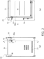
Fig. 2A is a rear view of the constant-temperature unit inFig. 1 , andFig. 2B is a cross-sectional view along the A-A line of the constant-temperature unit inFig. 2A ; -
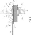
Fig. 3 is a cross-sectional view of a cable cover that is fixed to a measurement hole attached to the constant-temperature unit ofFig. 1 and holds a cable; -
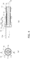
Fig. 4A is a front view of the cable cover holding the cable ofFig. 3 , andFig. 4B is a cross-sectional view along the B-B line inFig. 4A ; -
Fig. 5 is an overall oblique view of the configuration of the cable cover holding the cable inFig. 3 ; -
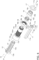
Fig. 6 is an exploded oblique view of the configuration of components included in the cable cover ofFig. 5 ; -
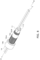
Fig. 7 is an assembly diagram showing a state in which the grommet included in the component configuration inFig. 6 is attached to a cable; -
Fig. 8 is an assembly diagram showing a state in which a sleeve member is mounted around the outer periphery of the grommet inFig. 7 ; -
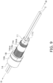
Fig. 9 is an assembly diagram showing a state in which a nut member is attached around the outer periphery of the sleeve member inFig. 8 ; -
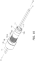
Fig. 10 is an assembly diagram showing a state in which a distal end cap is attached to the distal end of the sleeve member inFig. 9 ; -
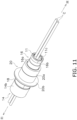
Fig. 11 is an assembly diagram showing a state in which the cable cover holding the cable inFig. 10 has been inserted into a measurement hole; -
Fig. 12 is an assembly diagram showing a state in which a sealing member has been mounted from the internal space side of an incubator in the sleeve member of the cable cover inserted into the measurement hole inFig. 11 ; -
Fig. 13 is an assembly diagram showing a state in which the sleeve member has been pulled from the external space side of the constant-temperature unit in the state shown inFig. 12 ; -
Fig. 14 is an assembly diagram showing a state in which the nut member has been moved from the state shown inFig. 13 to a position according to the size of the measurement hole, and then tightened; -
Figs. 15A and 15B are side views of cable covers mounted to measurement holes of different lengths; -
Fig. 16A is a cross-sectional view showing a tapered portion provided on the inner peripheral surface side of the distal end cap,Fig. 16B is a cross-sectional view showing a state in which the distal end cap is mounted to the distal end of an outer sleeve, andFig. 16C is a cross-sectional view showing elastic deformation of the intermediate member when the distal end cap is mounted to the distal end of the outer sleeve; -
Fig. 17 is an oblique view of the configuration of the cable cover according to a second embodiment of the present invention; -
Fig. 18 is an exploded oblique view of the component configuration of the cable cover shown inFig. 17 ; -
Fig. 19 is a cross-sectional view showing a state in which the cable cover inFig. 17 has been fixed to the measurement hole of the constant-temperature unit ofFig. 1 ; -
Fig. 20 is an oblique view of the configuration of the cable cover according to a third embodiment of the present invention; -
Fig. 21 is an exploded oblique view of the component configuration of the cable cover inFig. 20 ; and -
Fig. 22 is a cross-sectional view showing a state in which the cable cover inFig. 20 has been fixed to the measurement hole of the constant-temperature unit inFig. 1 and holds a cable. - A
cable cover 10 according to an embodiment of the present invention, and an incubator (constant-temperature unit) 30 including the same will now be described with reference toFigs. 1 to 16c . - In this embodiment, some unnecessarily detailed description may be omitted. For example, detailed description of already known facts or redundant description of components that are substantially the same may be omitted. This is to avoid unnecessary repetition in the following description, and facilitate an understanding on the part of a person skilled in the art.
- The applicant has provided the appended drawings and the following description so that a person skilled in the art might fully understand this disclosure, but does not intend for these to limit what is discussed in the patent claims.
- As shown in
Fig. 1 , thecable cover 10 in this embodiment fixes a cable C (seeFig. 7 , etc.) that is passed from the internal space S2 to the external space S1 through a measurement hole (installation hole) 20 provided on the rear surface (wall surface) 32 of an incubator (constant-temperature unit) 30. - As shown in
Fig. 1 , in the constant-temperature unit 30, a measurement device (not shown) that makes various measurements of cell culture, etc., is placed in an internal space S2 formed in ahousing 31, and the cable C for supplying power to the measurement device or transmitting and receiving various kinds of signal is passed through to the external space S1. The constant-temperature unit 30 is set such that the internal space S2 has an environment of high temperature and humidity environment (such as 37 degrees and 80%) in order to maintain the environment of the cells to be cultured. Accordingly, when the temperature in the external space S1 is low (such as 25 degrees or lower), condensation may occur near themeasurement hole 20 on the cable C passed through from the internal space S2 to the external space S1, and on the inner wall near themeasurement hole 20 in the internal space S2. - The anti-condensation structure provided by the
cable cover 10 of this embodiment will be described in detail at a later point. - As shown in
Figs. 2A and 2B , the constant-temperature unit 30 has ameasurement hole 20 provided in arecess 32a provided on therear surface 32 in order to pass the cable C from the internal space S2 of thehousing 31 into the external space S1. - The
measurement hole 20 is a cylindrical member to which thecable cover 10 holding the cable C is fixed, and is provided in a through-hole that goes through therear surface 32. As shown inFig. 3 , themeasurement hole 20 has a substantially cylindricalmain body part 20a and aflange portion 20b. - As shown in
Fig. 3 , the substantially cylindricalmain body part 20a is inserted from the external space S1 side along the inner peripheral surface of a through-hole formed in therear surface 32, and then fixed. - As shown in
Fig. 3 , theflange portion 20b is formed on the external space S1 side of the substantially cylindricalmain body part 20a, and is provided so as to protrude outward in the radial direction from the outer peripheral surface at the end of themain body part 20a on the external space S1 side. Theflange portion 20b is fixed so as to make contact with the surface on the external space S1 side of therear surface 32. - As shown in
Fig. 3 , thecable cover 10 holding the cable C (seeFig. 7 , etc.) is attached to themeasurement hole 20. - As shown in
Figs. 4A and 4B , thecable cover 10 includes a grommet (holding member) 11, a core sleeve (first sleeve member, sleeve member) 12, a heater (heating unit) 13, an outer sleeve (second sleeve member, sleeve member) 14, anintermediate member 15, a distal end cap (cap member) 16, a sealingmember 17, and a nut member (fixing member) 18. - The grommet (holding member) 11 is, for example, a member made of silicone rubber, and envelops the cable C while elastically deforming, and holds the outer peripheral portion of the cable C. The
grommet 11 has amain body part 11a that constitutes the center portion of thecable cover 10, and a holdingportion 11b that holds four cables C (seeFig. 7 , etc.). - In this embodiment, a configuration is described in which the four cables C are held in the
grommet 11, but the number of cables C held, that is, the number of holdingportions 11b, is not limited to four. - The
main body part 11a is a substantially cylindrical member and has grooves for holding the four cables C in its outer peripheral surface. - The holding
portions 11b are provided at the end on the internal space S2 side of themain body part 11a, and hold the cables C that are passed through a cut portion 11ba (seeFigs. 6 and7 ) while being elastically deformed. - Of the holding
portions 11b for holding the four cables C, those that are not holding a cable C allow the internal space S2 of the constant-temperature unit 30 to communicate with the external space S1, so in this embodiment, the holdingportions 11b are blocked off with plugs (blocking members) 11c made of silicone rubber, as shown inFig. 5 . - The substantially cylindrical core sleeve (first sleeve member, sleeve member) 12 is, for example, a substantially cylindrical member made of aluminum, which has high thermal conductivity, and the
grommet 11 is inserted and attached from the distal end thereof. A sheet-shapedheater 13 is wrapped around the outer peripheral surface of thecore sleeve 12. - The
main body part 12a is a substantially cylindrical member, and is provided with aflange portion 12b at the end on the external space S1 side. - As shown in
Fig. 6 , theflange portion 12b protrudes outward in the radial direction from the outer peripheral surface of themain body part 12a, and includes a portion that where aheater wire 13a (seeFigs. 3 and4b ) of the heater 13 (discussed below) is passed through to the outside. - As shown in
Fig. 6 , acut portion 12c is formed so as to split the outer peripheral surface of the substantially cylindricalmain body part 12a in two along the axial direction. - This makes it easier to attach the cables C held by the
grommet 11 when inserting thegrommet 11 from the distal end of thecore sleeve 12. - The heater (heating unit) 13 is disposed on the outer peripheral surface of the
main body part 12a of thecore sleeve 12, as shown inFig. 6 , in order to heat the portion of the cables C near themeasurement hole 20, and applies heat to the cables C held in thegrommet 11 enveloped by thecore sleeve 12. - This heats the outer peripheral surface of the cables C near the
measurement hole 20. Consequently, even if the temperature of the external space S1 is 25 degrees or lower, for example, it is possible to suppress the occurrence of condensation on the outer peripheral surface of the cables C near themeasurement hole 20 and near themeasurement hole 20 in the internal space S2 by heating the surface of the cables C to a temperature equal to or higher than the temperature of the internal space S2. - As shown in
Fig. 3 , etc., theheater wire 13a is connected to theheater 13 provided on the outer peripheral surface of themain body part 12a of thecore sleeve 12 in order to supply power to theheater 13, and is passed through to the external space S1. If the temperature of the outer surface of a cable C to be heated exceeds a specific temperature setting, for example, the supply of power from theheater wire 13a to theheater 13 is halted, and once the temperature falls below the set temperature, the supply of power to theheater 13 is started. - The outer sleeve (second sleeve member, sleeve member) 14 is a substantially cylindrical member made of resin such as PC ( polycarbonate ), and is attached so as to cover the outer periphery of the
core sleeve 12 and theheater 13. As shown inFig. 6 , theouter sleeve 14 has amain body part 14a, alarge diameter portion 14b, asmall diameter portion 14c, threaded portions 14ca and 14cb, and acut portion 14d. - As shown in
Fig. 6 , themain body part 14a is configured by linking two substantially cylindrical members (thelarge diameter portion 14b and thesmall diameter portion 14c) having different outside diameters. - The
large diameter portion 14b is a substantially cylindrical member on the side of themain body part 14a that has a larger outside diameter, and envelops theflange portion 12b of thecore sleeve 12. - The
small diameter portion 14c is a substantially cylindrical member on the side of themain body part 14a that has a smaller outside diameter, and envelops theheater 13 disposed on the outer peripheral surface of themain body part 12a of thecore sleeve 12. - As shown in
Fig. 6 , the threaded portion (first threaded portion) 14ca is formed along the lengthwise direction of the cables C on the outer peripheral surface in the middle part of the substantially cylindricalmain body part 14a, and a nut member 18 (discussed below) is threaded onto the threaded portion 14ca. - As shown in
Fig. 6 , the threaded portion 14cb is formed on the outer peripheral surface of the end portion on the internal space S2 side of themain body part 14a, and is fixed in a state in which a threadedportion 16c of the distal end cap 16 (discussed below) has been threaded on. - As shown in
Fig. 6 , thecut portion 14d is formed so as to split the outer peripheral surface of the substantially cylindricalmain body part 14a in two along the axial direction. Thecore sleeve 12 is then inserted from the distal end of theouter sleeve 14 toward the inner peripheral surface side in a state in which thecut portion 14d is open. - As shown in
Fig. 6 , theintermediate member 15 is a substantially cylindrical member that is disposed on the side of theouter sleeve 14 where the end (second end) on the internal space S2 side is located, and has substantially the same outside diameter as theouter sleeve 14. Theintermediate member 15 has amain body part 15a and slits 15b. - The
main body part 15a is a substantially cylindrical member made of PTFE (polytetrafluoroethylene) and is enveloped on the inner peripheral surface side of thedistal end cap 16. - A plurality of the
slits 15b are formed around the outer peripheral surface of themain body part 15a and running in the lengthwise direction of the cables C. When thedistal end cap 16 is attached to the outer peripheral surface side of theintermediate member 15, an external force is exerted inward in the radial direction by the taperedportion 16d (seeFig. 16A ) provided on the inner peripheral surface side of thedistal end cap 16, causing the cables C to elastically deform as shown inFigs. 16B and 16C . - This deformation of the
intermediate member 15 creates a waterproof structure near themeasurement hole 20. - The distal end cap (cap member) 16 is a substantially cylindrical member made of a resin such as PC (polycarbonate) and, as shown in
Fig. 6 , is attached so as to cover the end on the internal space S2 side of theouter sleeve 14 and the outer peripheral surface of theintermediate member 15. Thedistal end cap 16 has amain body part 16a, arecess 16b, a threadedportion 16c, and a taperedportion 16d. - The
main body part 16a is a substantially cylindrical member. - The
recess 16b is a groove into which a sealing member 17 (discussed below) fits, and is provided near the approximate center of themain body part 16a. - The threaded
portion 16c meshes with the above-mentioned threaded portion 14cb of theouter sleeve 14. This allows thedistal end cap 16 to be fixed to the end on the internal space S2 side of theouter sleeve 14. - The tapered
portion 16d is provided on the inner peripheral surface side of the substantially cylindricalmain body part 16a, and as shown inFig. 16A , is formed so that its inside diameter decreases toward the internal space S2 side. - Consequently, when the
distal end cap 16 is attached to the distal end of theouter sleeve 14, the taperedportion 16d comes into contact with the outer peripheral surface of themain body part 15a of theintermediate member 15 and presses it toward the inside diameter side, as shown inFig. 16B . Therefore, when the mounting of thedistal end cap 16 to the distal end of theouter sleeve 14 is complete, the portion of themain body part 15a of theintermediate member 15 where the taperedportion 16d comes into contact elastically deforms toward the inside diameter side, as shown inFig. 16C . - Consequently, a waterproofing mechanism can be formed in the
measurement hole 20 by the elastic deformation of themain body part 15a of theintermediate member 15 as thedistal end cap 16 is mounted to the distal end of theouter sleeve 14. - As shown in
Fig. 6 , the sealingmember 17 is, for example, a substantially annular member made of silicone rubber, which is mounted to the outer peripheral surface of thedistal end cap 16 and has an elasticmain body part 17a and acut portion 17b. The sealingmember 17 is inserted into themeasurement hole 20 to seal the space on the indoor side from the outdoor side. - The
main body part 17a is a substantially annular elastically deformable member, and is attached to therecess 16b of thedistal end cap 16 in a state in which thecut portion 17b has been opened. - The
cut portion 17b is formed so as to split the outer peripheral surface of the substantially annularmain body part 17a in two along the axial direction. Consequently, themain body part 17a can be attached to therecess 16b of thedistal end cap 16 by opening thecut portion 17b while elastically deforming themain body part 17a. - The
nut member 18 is a fastening member made of polycarbonate (PC) or another such resin, and as shown inFig. 6 , has a substantially annularmain body part 18a and a threaded portion (second threaded portion) 18b that is formed on the inner peripheral side of themain body part 18a and meshed with the threaded portion 14ca on theouter sleeve 14. Thenut member 18 is fixed at a position according to the length of themeasurement hole 20 in a state in which the threadedportion 18b is meshed with the threaded portion 14ca on theouter sleeve 14 side. - Here, the threaded
portion 18b of thenut member 18 meshes with the threaded portion 14ca formed near the center of themain body part 14a of theouter sleeve 14, and therefore does not mesh with the threaded portion 14cb formed at the end on the internal space S2 side. - That is, since the threaded portion 14cb has a smaller outside diameter than the threaded portion 14ca, the
nut member 18 can be inserted into the threaded portion 14ca side without meshing with the threadedportion 18b of thenut member 18. - The process of assembling the
cable cover 10 in this embodiment will now be described with reference toFigs. 7 to 14 . - On the external space S1 side of the cables C passed from the internal space S2 of the constant-
temperature unit 30 to the external space S1, thegrommet 11 is attached so as to hold the outer peripheral surface of the cables C, as shown inFig. 7 . - At this point, the
main body part 11a of thegrommet 11 is elastically deformed, and the cut portions 11ba formed in the four holdingportions 11b are opened so that the cables C can be held in the holdingportions 11b. - Of the four holding
portions 11b of thegrommet 11, aplug 11c is inserted into any holdingportion 11b that does not hold a cable C, as shown inFig. 7 . - Next, as shown in
Fig. 8 , sleeve members (core sleeve 12 and outer sleeve 14) are mounted so that thegrommet 11 holding the cables C covers the outer periphery. - At this point, the
grommet 11 is inserted from the distal end of thecore sleeve 12 and is held on the inner peripheral surface side. - Next, as shown in
Fig. 9 , thenut member 18 is attached so as to mesh with the threaded portion 14ca provided on the outer periphery of theouter sleeve 14. - At this point, the
nut member 18 turns and moves to the end on the external space S1 side in a state of being meshed with the threaded portion 14ca. - Next, as shown in
Fig. 10 , thedistal end cap 16 is attached to the end of thesmall diameter portion 14c in themain body part 14a of theouter sleeve 14. Thedistal end cap 16 is fixed when the threadedportion 16c formed on its inner peripheral surface meshes with the threaded portion 14cb formed on the end of thesmall diameter portion 14c. - Next, the components shown in
Fig. 10 are inserted from theexternal space S 1 side into themeasurement hole 20 fixed in therecess 32a in therear surface 32 of thehousing 31 of the constant-temperature unit 30. - At this point, the components in
Fig. 10 are inserted until thenut member 18 attached to the threaded portion 14ca of thelarge diameter portion 14b of theouter sleeve 14 hits theflange portion 20b of themeasurement hole 20, as shown inFig. 11 . - Next, as shown in
Fig. 12 , thecut portion 17b of themain body part 17a is opened from the internal space S2 side and the sealingmember 17 is attached in therecess 16b of themain body part 16a of thedistal end cap 16. - Next, from the state shown in
Fig. 12 , theouter sleeve 14 is pulled to the external space S1 side as shown inFig. 13 to change its position relative to themeasurement hole 20. - At this point, the end of the
main body part 20a on the internal space S2 side of themeasurement hole 20 moves to a position where it hits themain body part 17a of the sealingmember 17. - Next, from the state shown in
Fig. 13 , thenut member 18 is turned to move over the threaded portion 14ca of theouter sleeve 14 to the internal space S2 side as shown inFig. 14 , and thenut member 18 is fixed at a position where it presses against theflange portion 20b of themeasurement hole 20. - As a result, the
cable cover 10 is fixed to themeasurement hole 20 attached to therear surface 32 of thehousing 31 of the constant-temperature unit 30. - Then, in a state in which the
cable cover 10 is holding a plurality of cables C, and is fixed with respect to themeasurement hole 20 attached to therear surface 32 of the constant-temperature unit 30, current is sent to theheater 13, which heats the cables C near themeasurement hole 20. - This to more effectively prevents condensation from occurring near the
measurement hole 20 in thecable cover 10, which fixes the cables C that have been passed from the internal space S2 of the constant-temperature unit 30 to the external space S1 through themeasurement hole 20 provided on therear surface 32 of the constant-temperature unit 30, to themeasurement hole 20. - Also, in the constant-
temperature unit 30 or other such constant-temperature unit to which thecable cover 10 of this embodiment is attached, the length of themeasurement hole 20 may vary from one device to the next. - In view of this, as shown in
Figs. 15A and 15B , thecable cover 10 of this embodiment can be attached to both of the measurement holes 20 and 120, which have different lengths, by changing the fixing position of thenut member 18 that meshes with the threaded portion 14ca provided on the outer peripheral surface of theouter sleeve 14. - More precisely, if we let L1 be the length of the
measurement hole 20 and let L2 be the length of themeasurement hole 120, when L1 < L2, as shown inFig. 15A , thecable cover 10 is fixed when thenut member 18 moves a long distance to the position where it hits theflange portion 20b for ashort measurement hole 20. - Similarly, as shown in
Fig. 15B , thecable cover 10 is fixed when thenut member 18 moves a short distance to the position where it hits theflange portion 120b for along measurement hole 120. - Consequently, the
cable cover 10 of this embodiment can be attached to either of the measurement holes 20 and 120 attached to the constant-temperature unit 30 or other such constant-temperature unit, even though the measurement holes 20 and 120 have different lengths. - A
cable cover 110 according to another embodiment of the present invention will now be described with reference toFigs. 17 to 19. Figs. 17 to 19 show a state in which the cables C are not held in thecable cover 110. - As in
Embodiment 1 above, thecable cover 110 of this embodiment fixes cables C (seeFig. 7 , etc.) that are passed from the internal space S2 to the external space S1 through ameasurement hole 20 attached to the constant-temperature unit 30 or other such constant-temperature unit. - As shown in
Figs. 17 and18 , thecable cover 110 has a grommet (holding member) 111, a core sleeve (first sleeve member) 112, a sheet heater (heating unit) 113, and an outer sleeve (second sleeve member) 114. - The grommet (holding member) 111 is, for example, a member made of silicone rubber, which envelops the cables C while being elastically deformed, and holds the outer peripheral portion of the cables C. The
grommet 111 has amain body part 111a that constitutes the center portion of thecable cover 110, acylindrical portion 111b that is linked to themain body part 111a and has a larger outside diameter than themain body part 111a, and a holdingportion 111c that holds four cables C (seeFig. 7 , etc.). - Also, the
grommet 111 has cut portions 111ba that are provided on the outer peripheral surface of thecylindrical portion 111b and that elastically deform when the cables C are held by the holdingportion 111c, thereby moving the cables C to the holdingportion 111c. - Of the holding
portions 111c that hold the four cables C, any holdingportion 111c that does not hold a cable C is blocked off with a resin plug (blocking member) 111d. This makes it less likely that the internal space S2 of the constant-temperature unit 30 and the external space S1 will communicate with each other via any holdingportions 111c that do not hold cables C. - In this embodiment, a configuration is described in which four cables C are held in the
grommet 111, but the number of cables C held, that is, the number of holdingportions 111c, is not limited to four. - Furthermore, as shown in
Fig. 19 , thegrommet 111 has a press-fit portion 111e that hits the inner peripheral surface of themeasurement hole 20 when installed in themeasurement hole 20, and is held in place by the elastic deformation of thecylindrical portion 111b. - As shown in
Fig. 19 , when thecylindrical portion 111b is inserted into themeasurement hole 20 from the internal space S2 side, it elastically deforms at the part of the press-fit portion 111e provided on the outer peripheral surface, exerting an elastic force outward in the radial direction. - This allows the outer peripheral surface of the
cylindrical portion 111b to be held on the inner peripheral surface of themeasurement hole 20. - The core sleeve (first sleeve member) 112 is a member that is made by cutting aluminum, for example, and is disposed on the outer peripheral side of the
grommet 111, and as shown inFig. 18 , has a substantially cylindricalmain body part 112a and a cut portion 112ab provided along the lengthwise direction of themain body part 112a. - The cut portion 112ab is a gap formed along the lengthwise direction so as to split the substantially cylindrical
main body part 112a in the peripheral direction. - The sheet heater (heating unit) 113 is disposed on the outer peripheral surface of the
main body part 112a of thecore sleeve 112 as shown inFig. 19 in order to heat a part of the cables C near themeasurement hole 20, and applies heat to the cables C held in thegrommet 111 enveloped by thecore sleeve 112. - This heats the outer peripheral surface of the cables C near the
measurement hole 20. Consequently, even if the temperature of the external space S1 is 25 degrees or lower, for example, it is possible to suppress the occurrence of condensation on the outer peripheral surface of the cables C near themeasurement hole 20 and near themeasurement hole 20 in the internal space S2 by heating the surface of the cables C to a temperature equal to or higher than the temperature of the internal space S2. - As shown in
Fig. 18 , thesheet heater 113 has amain body part 113a, aretainer 113b, and aheater wire 113c. - The
main body part 113a is a sheet-like member and has a connection portion 113aa that is connected to theheater wire 113c, and a cut portion 113ab that is formed along the lengthwise direction so as to split the substantially cylindricalmain body part 113a in the peripheral direction. - The
retainer 113b is a member that latches theheater wire 113c so that this wire will not come loose, and is mounted on the external space S1 side of themain body part 113a. - The
heater wire 113c is connected to the connection portion 113aa of themain body 113a, is provided in order to supply power to thesheet heater 113, and is passed out to the external space S1. If the temperature of the outer surface of the cables C to be heated exceeds a specific temperature setting, for example, the supply of power from theheater wire 113c to thesheet heater 113 is halted, and if the temperature falls below the temperature setting, the supply of power to thesheet heater 113 is started. - The outer sleeve (second sleeve member) 114 is formed, for example, by cutting a resin, and is a member that is disposed on the outer peripheral surface side of the
core sleeve 112 and thesheet heater 113. As shown inFig. 18 , theouter sleeve 114 has a substantially cylindricalmain body part 114a, an arc portion 114aa that is provided at the end of themain body part 114a on the external space S1 side, and a cut portion 114ab that is provided along the lengthwise direction of themain body part 114a. - The arc portion 114aa is provided at the end of the
main body part 114a on the external space S1 side, is formed so that the end of themain body part 114a is split in the peripheral direction, and is a substantially arc-shaped portion when viewed from the external space S1 side. The connecting portion 113aa is disposed so as to be in contact with the portion that is split in the peripheral direction where the arc portion 114aa is provided, as shown inFigs. 17 and19 . - The cut portion 114ab is formed along the lengthwise direction so as to split the substantially cylindrical
main body part 114a in the peripheral direction. When thegrommet 111 to which the cables C are attached is put in place, thegrommet 111 is inserted from the distal end side of theouter sleeve 114 and is held on the inner peripheral surface side of themain body part 114a. - With the
cable cover 110 in this embodiment, as discussed above, thegrommet 111 has the press-fit portion 111e that hits the inner surface of themeasurement hole 20 when installed in themeasurement hole 20 and is held in place by the elastic deformation of thecylindrical portion 111b (seeFig. 19 ). - This makes use of the elasticity of the
grommet 111 to press the outer surface of thegrommet 111 into contact with the inner peripheral surface of themeasurement hole 20, so that thecable cover 110 can be easily fixed to themeasurement hole 20 without having to use any screws or other such fixing members. - Also, as shown in
Fig. 19 , thesheet heater 113 is disposed around the outer peripheral surface of themain body part 112a of thecore sleeve 112, and applies heat to the cables C held in thegrommet 111 contained enveloped by thecore sleeve 112. - This allows a portion of the cables C near the
measurement hole 20 to be heated, which effectively prevents condensation from forming on the surface of the cables C. - A
cable cover 210 according to yet another embodiment of the present invention will now be described with reference toFigs. 20 to 22 .Figs. 20 and21 show thecable cover 210 in a state of not holding any cables C, andFig. 22 shows thecable cover 210 in a state of holding the cables C. - The
cable cover 210 of this embodiment, just as with the cable covers 10 and 110 of the above Embodiments 1 and 2, fixes cables C (seeFig. 22 , etc.) that are passed from the internal space S2 to the external space S1 through ameasurement hole 20 attached to anincubator 30 or other such constant-temperature unit. - As shown in
Figs. 20 and21 , thecable cover 210 has a silicone plug (second holding member) 211, an aluminum block (first holding member) 212, and a cartridge heater (heating unit) 213. - As shown in
Fig. 20 , the silicone plug (second holding member) 211 is disposed the closest to the internal space S2 of all the members constituting thecable cover 210. Thesilicone plug 211 is disposed so as to be in contact with the aluminum block (first holding member) 212 in the direction in which the cables C extend, and has amain body part 211a, holding portions 211aa, and cut portions 211ab. - The
main body part 211a is a substantially cylindrical elastic member made of silicone rubber, for example. - The holding portions 211aa are four through-holes provided along the lengthwise direction of the
main body part 211a, and hold the cables C. This allows thecable cover 210 to hold four cables C in the four holding portions 211aa. - The cut portions 211ab are provided on the outer peripheral surface of the
main body part 211a, and elastically deform to open when the cables C are to be held in the holding portions 211aa, thereby moving the cables C to the holding portions 211aa. - Among the holding portions 211aa that hold the four cables C, any holding portion 211aa that does not hold a cable C is blocked off with a resin plug (blocking member) 211b. This prevents the internal space S2 of the constant-
temperature unit 30 and the external space S1 from communicating with each other through holding portions 211aa that do not hold cables C. - Also, the
silicone plug 211 has a press-fit portion 211c that hits the inner peripheral surface of themeasurement hole 20 when installed in themeasurement hole 20 and is held in place by elastic deformation. - The
silicone plug 211 hits the inner peripheral surface of themeasurement hole 20 when installed in themeasurement hole 20, and is held in place by the elastic deformation of themain body part 211a (seeFig. 22 ). - This makes use of the elasticity of the
silicone plug 211 to press the outer surface of thesilicone plug 211 into contact with the inner surface of themeasurement hole 20, so that thecable cover 210 can be easily fixed to themeasurement hole 20. - The aluminum block (first holding member) 212 is formed by cutting a block of aluminum, and has a substantially cylindrical
main body part 212a, a plurality of holding portions 212aa provided to themain body part 212a, and a substantially cylindrical insertion hole 212ab provided in the center of themain body part 212a. - As shown in
Fig. 21 , the insertion hole 212ab is a through-hole formed along the center axis of the substantially cylindricalmain body part 212a, and has an inside diameter that is slightly larger than the outside diameter of themain body part 213a of thecartridge heater 213. Thecartridge heater 213 is inserted into the insertion hole 212ab. - The holding portions 212aa are provided on the outer peripheral side of the insertion hole, and each holds a cable C. In this embodiment, a configuration is described in which four cables C are held in the
aluminum block 212, but the number of cables C held, that is, the number of holding portions 212aa, is not limited to four. - The
aluminum block 212 has a plurality of holding portions 212aa provided on the outer peripheral surface of themain body part 212a. - As shown in
Fig. 21 , the holding portions 212aa are provided along the lengthwise direction at approximately equal angular intervals on the outer peripheral surface of the substantially cylindricalmain body part 212a, and are recesses into which the cables C are fitted from the outer peripheral side. - The
aluminum block 212 is formed from a metal material having high thermal conductivity, such as aluminum. Consequently, the heat coming off thecartridge heater 213 can be efficiently transferred to the cables C. - As shown in
Fig. 21 , the cartridge heater (heating unit) 213 is a rod-shaped heating element, and as shown inFig. 22 , is inserted into the insertion hole 212ab formed along the center axis of thealuminum block 212. Thecartridge heater 213 has amain body part 213a, aflange portion 213b, aheater wire 213c, and ascrew 213d. - The
main body part 213a is a substantially cylindrical rod-shaped member, and is connected to theheater wire 213c. - The
flange portion 213b protrudes outward in the radial direction from the outer peripheral surface of the substantially cylindricalmain body part 213a, and is fixed to the end surface of thealuminum block 212 by means of thescrew 213d. - The
flange portion 213b may be fixed to thealuminum block 212 by some other means besides a screw, such as an adhesive agent. - The
heater wire 213c is connected to themain body part 213a, is provided in order to supply power to thecartridge heater 213, and is passed through to the external space S1 side. If the temperature of the outer surface of the cables C to be heated exceeds a specific temperature setting, for example, the power supply from theheater wire 213c to thecartridge heater 213 is halted, and if the temperature falls below the temperature setting, the power supply to thecartridge heater 213 is started. - As described above, the
cable cover 210 of this embodiment has a press-fit portion 211c in which thesilicone plug 211 comes into contact with the inner surface of themeasurement hole 20 when installed in themeasurement hole 20, and is held in place by the elastic deformation of themain body part 211a (seeFig. 22 ). - This makes use of the elasticity of the
silicone plug 211 to press the outer surface of thesilicone plug 211 into contact with the inner peripheral surface of themeasurement hole 20, so that thecable cover 210 can be easily fixed to themeasurement hole 20 without having to use any screws or other such fixing members. - As shown in
Fig. 22 , etc., thecartridge heater 213 is disposed near the center axis of themain body part 212a of thealuminum block 212, and applies heat to the cables C held on the outer peripheral surface side of thealuminum block 212. - This allows a portion of the cables C near the
measurement hole 20 to be heated, which effectively prevents condensation from forming on the surface of the cables C. - Embodiments of the present invention were described above, but the present invention is not limited to or by the above embodiments, and various modifications are possible without departing from the gist of the invention.
- (A) In the above embodiments, an example was given in which the sleeve member employed a two-layer structure including the
core sleeve 12 and theouter sleeve 14. However, the present invention is not limited to this.
For example, the sleeve member may be made up of just a single member. - (B) In the above embodiments, an example was given in which a substantially cylindrical member (measurement hole 20) was fixed to the rear surface (wall surface) 32 on the constant-
temperature unit 30 side to which thecable cover 10 was attached. However, the present invention is not limited to this.
For example, components on the constant-temperature unit side where the cable cover is attached may be directly attached to the wall surface. - (C) In the above embodiments, an example was given in which the sheet-shaped
heater 13 was wrapped around the outer peripheral surface of thecore sleeve 12 in order to prevent condensation from occurring near themeasurement hole 20. However, the present invention is not limited to this.
For example, the heating unit used to prevent condensation may be in some form other than a sheet. - (D) In the above embodiments, an example was given in which the
cable cover 10 held four cables C. However, the present invention is not limited to this.
For example, the cable cover may be configured to hold one to three cables, or configured to hold five or more cables. - (E) In the above embodiments, an example was given in which the constant-
temperature unit 30 that performed cell culture was used as the constant-temperature unit to which thecable cover 10 of the embodiments was attached. However, the present invention is not limited to this.
For example, the constant-temperature unit to which the cable cover is attached is not limited to being an incubator, and may instead be any of various kinds of constant-temperature unit used in environments of high temperature and/or high humidity. - (F) In
Embodiment 3 above, an example was given in which the silicone plug (second holding member) 211 and the aluminum block (first holding member) 212 were provided as separate members. However, the present invention is not limited to this. - For example, the first holding member and the second holding member may be configured as an integral member.
- Here again, the occurrence of condensation on the surface of the cables can be effectively suppressed by heating the cables with a heater or other such heating unit while the cables are held in a member that integrates the first and second holding members.
- In this case, the cable cover can be easily fixed to the measurement hole by press-fitting, just as in
Embodiments measurement hole 20 or on the outer peripheral side a member formed by integrating a first holding member and a second holding member, for example. - The cable cover of the present invention is a cable cover that fixes a cable that is passed from the inside to the outside through an opening provided in the wall of a constant-temperature unit, and exhibits the effect that the occurrence of condensation near the opening can be more effectively prevented, and as such can be widely applied to a variety of devices in which cables are passed from an indoor side to an outdoor side.
-
- 10
- cable cover
- 11
- grommet (holding member)
- 11a
- main body part
- 11b
- holding portion
- 11ba
- cut portion
- 11c
- plug (blocking member)
- 12
- core sleeve (first sleeve member, sleeve member)
- 12a
- main body part
- 12b
- flange portion
- 12c
- cut portion
- 13
- heater (heating unit)
- 13a
- heater wire
- 14
- outer sleeve (second sleeve member, sleeve member)
- 14a
- main body part
- 14b
- large diameter portion
- 14c
- small diameter portion
- 14ca
- threaded portion (first threaded portion)
- 14cb
- threaded portion
- 14d
- cut portion
- 15
- intermediate member
- 15a
- main body part
- 15b
- slit
- 16
- distal end cap (cap member)
- 16a
- main body part
- 16b
- recess
- 16c
- threaded portion
- 16d
- tapered portion
- 17
- sealing member
- 17a
- main body part
- 17b
- cut portion
- 18
- nut member (fixing member)
- 18a
- main body part
- 18b
- threaded portion (second threaded portion)
- 20
- measurement hole (installation hole)
- 20a
- main body part
- 20b
- flange portion
- 30
- constant-temperature unit (constant-temperature unit)
- 31
- housing
- 32
- rear surface (wall surface)
- 32a
- recess
- 110
- cable cover
- 111
- grommet (holding member)
- 111a
- main body part
- 111b
- cylindrical portion
- 111ba
- cut portion
- 111c
- holding portion
- 111d
- plug (blocking member)
- 111e
- press-fit portion
- 112
- core sleeve (first sleeve member)
- 112a
- main body part
- 112ab
- cut portion
- 113
- sheet heater (heating unit)
- 113a
- main body part
- 113aa
- connection portion
- 113ab
- cut portion
- 113b
- retainer
- 113c
- heater wire
- 114
- outer sleeve (second sleeve member)
- 114a
- main body part
- 114aa
- arc portion
- 114ab
- cut portion
- 120
- measurement hole (installation hole)
- 120b
- flange portion
- 210
- cable cover
- 211
- silicone plug (second holding member)
- 211a
- main body part
- 211aa
- holding portion
- 211ab
- cut portion
- 211b
- plug (blocking member)
- 211c
- press-fit portion
- 212
- aluminum block (first holding member)
- 212a
- main body part
- 212aa
- holding portion
- 212ab
- insertion hole
- 213
- cartridge heater (heating unit)
- 213a
- main body part
- 213b
- flange portion
- 213c
- heater wire
- 213d
- screw
- C
- cable
- S1
- external space
- S2
- internal space
Claims (21)
- A cable cover that fixes, in an installation hole provided in a wall surface of a constant-temperature unit, a cable coming out of an internal space, through the installation hole, and into an external space, the cable cover comprising:a holding member configured to hold the cable;a substantially cylindrical first sleeve member that is disposed around an outer periphery of the holding member; anda heating unit that is disposed on the first sleeve member and is configured to apply heat to the cable held via the first sleeve member by the holding member.
- A cable cover that fixes, in an installation hole provided in a wall surface of a constant-temperature unit, a cable coming out of the internal space, through the installation hole, and into the external space, the cable cover comprising:a first holding member configured to hold the cable;a second holding member that is disposed so as to come into contact with the first holding member each other in an extension direction of the cable; anda heating unit that is disposed on the first holding member and is configured to apply heat to the cable held by the first holding member via the first holding member.
- A cable cover that fixes, in an installation hole provided in a wall surface of a constant-temperature unit, a cable coming out of the internal space, through the installation hole, and into the external space, the cable cover comprising:a holding member configured to hold the cable;a substantially cylindrical sleeve member that is disposed around an outer periphery of the holding member and has a first threaded portion formed on an outer peripheral surface of the sleeve member along a lengthwise direction of the cable; anda fixing member that has a substantially annular main body part and a second threaded portion formed on an inner peripheral side of the main body part and meshing with the first threaded portion, and that is fixed at a position corresponding to a length of the installation hole in a state in which the second threaded portion is meshed with the first threaded portion.
- The cable cover according to claim 1,
further comprising a substantially cylindrical second sleeve member that is attached so as to cover the outer peripheries of the first sleeve member and the heating unit. - The cable cover according to claim 4,wherein the second sleeve member has a first threaded portion that is formed on the substantially cylindrical outer peripheral surface along a lengthwise direction of the cable, andthe cable cover further comprises a fixing member that has a substantially annular main body part and a second threaded portion formed on an inner peripheral side of the main body part and meshing with the first threaded portion, and that is fixed at a position corresponding to a length of the installation hole in a state in which the second threaded portion is meshed with the first threaded portion.
- The cable cover according to claim 4,wherein the second sleeve member has a first end on an outdoor side of the constant-temperature unit, and a second end on an indoor side,the cable cover further comprising an intermediate member that is disposed on a side of the second end of the second sleeve member and has substantially the same outside diameter as the second sleeve member; and a cap member that is attached so as to cover a second end of the second sleeve member and an outer peripheral surface of the intermediate member.
- The cable cover according to claim 6,
wherein mounting of the cap member causes the intermediate member to be deformed, forming a waterproofing mechanism in the installation hole. - The cable cover according to claim 6 or 7,
further comprising a sealing member that is mounted to an outer peripheral surface of the cap member, is elastic, and is inserted into the installation hole to seal off the internal space. - The cable cover according to claim 1 or 3,
wherein the holding member has a plurality of holding portions that hold a plurality of the cables. - The cable cover according to claim 9,
further comprising a blocking member configured to block off an end of a holding portion that is not holding the cable, among the plurality of holding portions of the holding member. - The cable cover according to claim 1 or 3,
wherein the holding member is elastic. - The cable cover according to claim 11,
wherein the holding member has a press-fit portion configured to make contact with an inner peripheral surface of the installation hole when installed in the installation hole, and is held by elastic deformation. - The cable cover according to claim 11,
wherein the holding member has a holding portion configured to hold the cable, and a cut portion that is provided in an outer peripheral surface thereof and that elastically deforms when the cable is held by the holding portion, thereby moving the cable to the holding portion. - The cable cover according to claim 2,wherein the first holding member has a substantially cylindrical insertion hole provided in a center thereof, andthe heating unit is inserted into the insertion hole.
- The cable cover according to claim 14,wherein the first holding member has a holding portion provided on an outer peripheral side of the insertion hole, andthe cable is held in the holding portion.
- The cable cover according to claim 15,wherein the first holding member has a plurality of the holding portions, andthe plurality of holding portions are recesses into which the cables are fitted from an outer peripheral side of the first holding member.
- The cable cover according to claim 2.
wherein the second holding member is formed by a substantially cylindrical elastic member. - The cable cover of claim 17,
wherein the second holding member has a holding portion configured to hold the cable, and a cut portion that is provided on an outer peripheral surface of the holding portion and elastically deforms when the cable is held by the holding portion, thereby moving the cable to the holding portion. - The cable cover of claim 17,
wherein the second holding member has a press-fit portion configured to make contact with an inner peripheral surface of the installation hole when installed in the installation hole, and is held by elastic deformation. - The cable cover according to claim 2,
wherein the first holding member is formed from a metal material having high thermal conductivity. - A constant-temperature unit, comprising:the cable cover according to any of claims 1 to 3; anda housing that includes a wall surface in which the installation hole is provided.
Applications Claiming Priority (2)
| Application Number | Priority Date | Filing Date | Title |
|---|---|---|---|
| JP2022156335 | 2022-09-29 | ||
| PCT/JP2023/027152 WO2024070171A1 (en) | 2022-09-29 | 2023-07-25 | Cable cover and constant-temperature unit provided with same |
Publications (1)
| Publication Number | Publication Date |
|---|---|
| EP4550955A1 true EP4550955A1 (en) | 2025-05-07 |
Family
ID=90477069
Family Applications (1)
| Application Number | Title | Priority Date | Filing Date |
|---|---|---|---|
| EP23871414.1A Pending EP4550955A1 (en) | 2022-09-29 | 2023-07-25 | Cable cover and constant-temperature unit provided with same |
Country Status (4)
| Country | Link |
|---|---|
| US (1) | US20250193972A1 (en) |
| EP (1) | EP4550955A1 (en) |
| JP (1) | JPWO2024070171A1 (en) |
| WO (1) | WO2024070171A1 (en) |
Family Cites Families (8)
| Publication number | Priority date | Publication date | Assignee | Title |
|---|---|---|---|---|
| JPS58103178U (en) * | 1981-12-28 | 1983-07-13 | 富士通フアナツク株式会社 | cord grip |
| JPS6232583U (en) * | 1985-08-14 | 1987-02-26 | ||
| JPH05240563A (en) * | 1992-02-28 | 1993-09-17 | Sanyo Electric Co Ltd | Device for preventing dewing in refrigerator |
| JPH1117363A (en) * | 1997-06-23 | 1999-01-22 | Tokyo Gas Co Ltd | Member seal structure |
| US6037544A (en) * | 1997-11-22 | 2000-03-14 | Lg Chemical Ltd | Splice closure for telecommunications cables |
| JP5017133B2 (en) | 2008-01-30 | 2012-09-05 | 三洋電機株式会社 | Thermostat and cover |
| JP2015115154A (en) * | 2013-12-11 | 2015-06-22 | オーウエル株式会社 | Lighting device |
| CN217341455U (en) * | 2022-04-08 | 2022-09-02 | 江苏佳世德检测技术有限公司 | Intelligent condensation preventing device for wire outlet hole of high-low temperature test box |
-
2023
- 2023-07-25 EP EP23871414.1A patent/EP4550955A1/en active Pending
- 2023-07-25 JP JP2024549788A patent/JPWO2024070171A1/ja active Pending
- 2023-07-25 WO PCT/JP2023/027152 patent/WO2024070171A1/en not_active Ceased
-
2025
- 2025-01-29 US US19/040,529 patent/US20250193972A1/en active Pending
Also Published As
| Publication number | Publication date |
|---|---|
| JPWO2024070171A1 (en) | 2024-04-04 |
| WO2024070171A1 (en) | 2024-04-04 |
| US20250193972A1 (en) | 2025-06-12 |
Similar Documents
| Publication | Publication Date | Title |
|---|---|---|
| US5942730A (en) | Threaded cable joint | |
| US7641522B2 (en) | Electrical-connection device, particularly for photovoltaic-cell solar panels | |
| US8668188B2 (en) | Slotted spring vibration isolator | |
| KR960701392A (en) | Electronic apparatus with fitting band | |
| CN104584352B (en) | Logical leading-in device for explosion-proof casing | |
| US9755412B2 (en) | Grommet for mounting cable gland or the like | |
| US20250193972A1 (en) | Cable cover and constant-temperature unit equipped with same | |
| EP3396798B1 (en) | Sealing body for telecommunication cables | |
| US9506634B1 (en) | Lamp structures and methods for mounting the same | |
| EP3339059B1 (en) | Tire state monitoring device | |
| US12419001B2 (en) | Cable threading component and sealing box | |
| US11904460B2 (en) | Robot linear-object unit and linear-object routing method | |
| US20020149157A1 (en) | Sealing gasket for cables | |
| EP2555362B1 (en) | Grommet and waterproof structure for grommet | |
| US12107364B2 (en) | Connector and connector-equipped electric wire | |
| JPH10326978A (en) | Cable waterproof structure of apparatus cabinet | |
| JP5154857B2 (en) | Endoscope system | |
| RU2013126974A (en) | INSULATION BUSHING FOR FLEXIBLE TUBE IN MOUNTING BOX | |
| KR100880050B1 (en) | Coaxial Cable Connectors with Friction Coupling Sleeves | |
| US6739598B1 (en) | Seal between a conduit and cable | |
| EP4251953B1 (en) | Encoder outlet structure and encoder | |
| ES2154239A1 (en) | Oxygen probe | |
| JPWO2024070171A5 (en) | ||
| JP6156159B2 (en) | Terminal block | |
| EP4231465A1 (en) | Electronic device and waterproof member thereof |
Legal Events
| Date | Code | Title | Description |
|---|---|---|---|
| STAA | Information on the status of an ep patent application or granted ep patent |
Free format text: STATUS: THE INTERNATIONAL PUBLICATION HAS BEEN MADE |
|
| PUAI | Public reference made under article 153(3) epc to a published international application that has entered the european phase |
Free format text: ORIGINAL CODE: 0009012 |
|
| STAA | Information on the status of an ep patent application or granted ep patent |
Free format text: STATUS: REQUEST FOR EXAMINATION WAS MADE |
|
| 17P | Request for examination filed |
Effective date: 20250203 |
|
| AK | Designated contracting states |
Kind code of ref document: A1 Designated state(s): AL AT BE BG CH CY CZ DE DK EE ES FI FR GB GR HR HU IE IS IT LI LT LU LV MC ME MK MT NL NO PL PT RO RS SE SI SK SM TR |
|
| RIN1 | Information on inventor provided before grant (corrected) |
Inventor name: IKETANI, SEIITIROU Inventor name: WATANABE, HIDENORI Inventor name: HIRATSUKA, TAKASHIGE Inventor name: HORIKAWA, KIYOHIRO Inventor name: HORIMOTO, NOBUO Inventor name: HIRAI, HIROKI Inventor name: NAKAMAE, KENTA |
|
| DAV | Request for validation of the european patent (deleted) | ||
| DAX | Request for extension of the european patent (deleted) |