EP4550926A1 - Method executed by means of user equipment, and user equipment - Google Patents

Method executed by means of user equipment, and user equipment Download PDF

Info

Publication number
EP4550926A1
EP4550926A1 EP23830409.1A EP23830409A EP4550926A1 EP 4550926 A1 EP4550926 A1 EP 4550926A1 EP 23830409 A EP23830409 A EP 23830409A EP 4550926 A1 EP4550926 A1 EP 4550926A1
Authority
EP
European Patent Office
Prior art keywords
sssb
bwp
cpe
subcarrier
ext
Prior art date
Legal status (The legal status is an assumption and is not a legal conclusion. Google has not performed a legal analysis and makes no representation as to the accuracy of the status listed.)
Pending
Application number
EP23830409.1A
Other languages
German (de)
French (fr)
Inventor
Yinan ZHAO
Renmao Liu
Chao LUO
Current Assignee (The listed assignees may be inaccurate. Google has not performed a legal analysis and makes no representation or warranty as to the accuracy of the list.)
Sharp Corp
Original Assignee
Sharp Corp
Priority date (The priority date is an assumption and is not a legal conclusion. Google has not performed a legal analysis and makes no representation as to the accuracy of the date listed.)
Filing date
Publication date
Application filed by Sharp Corp filed Critical Sharp Corp
Publication of EP4550926A1 publication Critical patent/EP4550926A1/en
Pending legal-status Critical Current

Links

Images

Classifications

    • HELECTRICITY
    • H04ELECTRIC COMMUNICATION TECHNIQUE
    • H04WWIRELESS COMMUNICATION NETWORKS
    • H04W72/00Local resource management
    • H04W72/04Wireless resource allocation
    • H04W72/044Wireless resource allocation based on the type of the allocated resource
    • H04W72/0453Resources in frequency domain, e.g. a carrier in FDMA
    • HELECTRICITY
    • H04ELECTRIC COMMUNICATION TECHNIQUE
    • H04WWIRELESS COMMUNICATION NETWORKS
    • H04W76/00Connection management
    • H04W76/20Manipulation of established connections
    • H04W76/23Manipulation of direct-mode connections
    • HELECTRICITY
    • H04ELECTRIC COMMUNICATION TECHNIQUE
    • H04LTRANSMISSION OF DIGITAL INFORMATION, e.g. TELEGRAPHIC COMMUNICATION
    • H04L5/00Arrangements affording multiple use of the transmission path
    • H04L5/0001Arrangements for dividing the transmission path
    • H04L5/0003Two-dimensional division
    • H04L5/0005Time-frequency
    • H04L5/0007Time-frequency the frequencies being orthogonal, e.g. OFDM(A) or DMT
    • HELECTRICITY
    • H04ELECTRIC COMMUNICATION TECHNIQUE
    • H04WWIRELESS COMMUNICATION NETWORKS
    • H04W76/00Connection management
    • H04W76/10Connection setup
    • H04W76/14Direct-mode setup

Definitions

  • the present invention relates to a method performed by user equipment, and user equipment.
  • UEs In a wireless communication system, UEs (user equipment) can perform sidelink (SL) communication with each other.
  • the SL communication may include general device-to-device (D2D) communication, vehicle-to-vehicle (V2V) communication, vehicle-to-everything (V2X) communication, and the like.
  • D2D device-to-device
  • V2V vehicle-to-vehicle
  • V2X vehicle-to-everything
  • a series of issues need to be solved, such as channel access mechanisms, physical layer channel and/or signal structures, physical layer procedures (e.g., a synchronization procedure, and feedback and/or a determination mechanism), resource allocation and/or management, and coexistence with other systems.
  • a method performed by user equipment, and user equipment More than one frequency location for an S-SS/PSBCH block is allowed to be configured, and the S-SS/PSBCH block corresponding to each frequency location is within a bandwidth of a unique RB set within an SL BWP, so that the probability that the S-SS/PSBCH block can still be transmitted when one or more channel access failures occur within the SL BWP is greatly increased, thereby improving the stability of a synchronization procedure of an SL link.
  • a method performed by user equipment is provided.
  • the method is characterized by comprising: determining one or more frequency locations within one SL BWP for S-SS/PSBCH block reception, wherein each frequency location corresponds to a center frequency of one subcarrier in one S-SS/PSBCH block, and a bandwidth of the S-SS/PSBCH block is within a bandwidth of a unique RB set within the SL BWP; and receiving the S-SS/PSBCH block in part or all of the one or more frequency locations.
  • user equipment comprising: a processor; and a memory, having instructions stored therein, wherein the instructions, when run by the processor, perform the above method.
  • a method More than one frequency location for an S-SS/PSBCH block is allowed to be configured, and the S-SS/PSBCH block corresponding to each frequency location is within a bandwidth of a unique RB set within an SL BWP, so that the probability that the S-SS/PSBCH block can still be transmitted when one or more channel access failures occur within the SL BWP is greatly increased, thereby improving the stability of a synchronization procedure of an SL link.
  • 5G or referred to as “New Radio" (NR) or 5G NR) wireless communication system specifications and later evolved versions thereof (e.g., 5G Advanced) formulated by the 3rd Generation Partnership Project (3GPP) are used as exemplary application environments to specifically describe a plurality of embodiments according to the present invention.
  • 3GPP 3rd Generation Partnership Project
  • the present invention is not limited to the following embodiments, but is applicable to many other wireless communication systems, such as wireless communication systems later than 5G, or such as 4G mobile communication systems earlier than 5G, e.g., Long Term Evolution (LTE), LTE-Advanced, LTE-Advanced Pro, etc.
  • LTE Long Term Evolution
  • LTE-Advanced LTE-Advanced Pro
  • 5G (or referred to as new radio (NR)) can operate in both a licensed spectrum (e.g., 2010 MHz to 2025 MHz) and an unlicensed spectrum (e.g., part or all of 5150 MHz to 5925 MHz, part or all of 5925 MHz to 7125 MHz, and part or all of 5925 MHz to 6425 MHz).
  • a licensed spectrum e.g., 2010 MHz to 2025 MHz
  • an unlicensed spectrum e.g., part or all of 5150 MHz to 5925 MHz, part or all of 5925 MHz to 7125 MHz, and part or all of 5925 MHz to 6425 MHz.
  • a 5G-capable communication node When 5G operates in an unlicensed spectrum, a 5G-capable communication node (or referred to as a “node”, such as a base station or UE) may perform a "channel access procedure" for a "channel” (or “shared-spectrum channel”).
  • One channel may correspond to one set consisting of several consecutive resource blocks (RBs).
  • An operation performed on one or more shared spectrum channels may be referred to as an “operation with shared spectrum channel access”.
  • an operation on a licensed spectrum may be referred to as an "operation without shared spectrum channel access”.
  • One channel may correspond to one carrier, or a part of one carrier.
  • one channel may correspond to one carrier of a 20 MHz bandwidth.
  • one channel may correspond to the lower 20 MHz part in one 40 MHz bandwidth carrier, and another channel may correspond to the higher 20 MHz part in the same carrier.
  • a channel access procedure may be used to assess whether a channel can be used to perform one or more transmissions (or referred to as "assessing whether one or more transmissions can be performed on a channel"), and the assessment operation may be referred to as clear channel assessment (CCA).
  • CCA clear channel assessment
  • Such a mechanism of performing CCA before using a channel may be referred to as Listen Before Talk (LBT).
  • LBT Listen Before Talk
  • the state of a channel may be determined on the basis of a "sensing" operation performed on the channel.
  • the "clear" channel state may indicate a channel access success, or indicate that a corresponding channel is available, or indicate that one or more transmissions may be performed on the channel.
  • the "busy" channel state may indicate a channel access failure, or indicate that a corresponding channel is unavailable, or indicate that no transmission can be performed on the channel).
  • sensing result of the channel in sensing slot durations in a "defer duration" may be determined to be clear.
  • N may be an integer greater than or equal to zero.
  • the period of time having the length T f may start with a sensing slot.
  • a corresponding channel cannot be accessed before a start time of an intended transmission (e.g., before the first symbol corresponding to the transmission) (e.g., the channel cannot be accessed because the state of the channel is "busy")
  • a channel access failure occurs, which may be alternatively referred to as an "LBT failure” where applicable.
  • a transmission performed on a corresponding channel after a channel access procedure is performed may be referred to as "channel occupancy” (CO), and a corresponding duration may be referred to as a “channel occupancy time” (COT).
  • COT channel occupancy
  • COT channel occupancy time
  • a COT may be shared between one or more communication nodes, and accordingly, the time corresponding to the COT may include a time for which the one or more communication nodes perform transmissions on respective channels, and a time corresponding to a transmission gap between the transmissions (e.g., when the duration of the transmission gap is less than or equal to 25 us ).
  • the channel access procedures may be classified into a plurality of types according to usage, applicable scenarios, etc. For example, if a time span of a sensing slot in which the sensing result is clear before transmission is performed is denoted as T last , intvl sns , T last , intvl sns is random in "channel access procedure type 1". In “channel access procedure type 2", T last , intvl sns is deterministic. Channel access procedure type 1 may be used for a non-shared COT or a shared COT. Channel access procedure type 2 may be used to perform channel access in a COT shared by one other communication node.
  • Channel access procedure type 2 may be divided, according to features of T last , intvl sns , into a plurality of sub-types, for example, one or more of the following:
  • a “multi-channel access procedure” refers to one or more channel access procedures that may be performed (e.g., performed in parallel) for performing one or more transmissions (e.g., multiple simultaneous transmissions) on a plurality of channels (e.g., a channel set corresponding thereto is denoted as CH acc ).
  • a channel ch j may be selected (e.g., uniformly, randomly) from the set CH sns and channel access procedure type 1 may be performed thereon, while channel access procedure type 2 (e.g., channel access procedure type 2A, or channel access procedure type 2B, or channel access procedure type 2C) or another channel access procedure that is not channel access procedure type 1 may be performed on each of the other channels in the set CH sns , and whether the one or more transmissions can be performed is determined according to corresponding results.
  • channel access procedure type 2 e.g., channel access procedure type 2A, or channel access procedure type 2B, or channel access procedure type 2C
  • another channel access procedure that is not channel access procedure type 1 may be performed on each of the other channels in the set CH sns , and whether the one or more transmissions can be performed is determined according to corresponding results.
  • a set of available resource blocks in a channel may be referred to as an "RB set".
  • a carrier e.g., denoted as c
  • N C RBset N C RBset ⁇ 1 RB sets respectively denoted as, for example, rs 0 , rs 1 , ⁇ , rs N C RBset ⁇ 1 .
  • the lowest indexed common resource block (CRB) and the highest indexed CRB of rs i may be respectively denoted as N i RS , start , N i RS , end .
  • the number of RBs of rs i may be denoted as N i RS , size , where N i RS , size may be equal to N i RS , end ⁇ N i RS , start + 1 .
  • N C GB N C RBset ⁇ 1 guard bands (or referred to as "intra-cell guard bands") for separating the N C RBset RB sets may be present in the carrier, and are respectively denoted as, for example, gb 0 , gb 1 , ... ... , gb N C GB ⁇ 1 .
  • the lowest indexed CRB and the highest indexed CRB of gb j may be respectively denoted as N j GB , start and N j GB , end .
  • the number of RBs of gb j may be denoted as N j GB , size , where N j GB , size may be equal to N j GB , end ⁇ N j GB , start + 1 , and gb j may be used to separate the RB set rs j and the RB set rs j + 1 .
  • RS C ⁇ rs 0 , rs 1 , ..., rs N C RBset ⁇ 1 .
  • GB C gb 0 , gb 1 , ... , gb N C GB ⁇ 1 .
  • N C BWP N C BWP ⁇ 1 bandwidth parts may be configured in the carrier c, and are respectively denoted as, for example, bwp 0 , bwp 1 , ... ... , bwp N C BWP ⁇ 1 .
  • rs ak,l is an element in the set RS C , and a k , 0 ⁇ a k , 1 ⁇ ⁇ ⁇ a k , N BWP , k RBset ⁇ 1 .
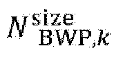
  • the lowest indexed CRB (e.g., denoted as N BWP , k start ) of bwp k may be equal to N a k , o RS , start
  • the number of RBs of bwp k e.g., denoted as N BWP , k size
  • N BWP , k RBset RB sets may be N BWP , k RBset consecutive RB sets.
  • N BWP , k RBset ⁇ 1 , a k, l a k, 0 + l.
  • N BWP , k RBset may be denoted as N BWP RBset
  • rs a k , 0 , rs a k , 1 , ... ... , rs a k , N BWP , k RBset ⁇ 1 may be respectively denoted as rs a 0 , rs a 1 , ⁇ , rs a N BWP RBset ⁇ 1 .
  • the set RS BWP may be equal to the set RS C or equal to a subset of the set RS C .
  • a certain restriction may be imposed on the power spectral density (PSD) and/or occupied channel bandwidth (OCB) of signal transmission.
  • PSD power spectral density
  • OCB occupied channel bandwidth
  • the maximum PSD cannot exceed 10 dBm/MHz.
  • the bandwidth containing 99% of the transmission power must be greater than or equal to a certain percentage (e.g., 80%) of the nominal channel bandwidth.
  • the restriction (if any) may be made and enforced by regulatory authorities.
  • the restrictions (if any) on the PSD and/or the OCB may be different in different countries or regions.
  • one radio transmission may correspond to one or more "interlaces".
  • the interlace int m may correspond to the CRB set ⁇ m, M INT + m, 2M INT + m, 3M INT + m, ... ⁇ .
  • M INT may be a predefined or configured or pre-configured value.
  • different "interlaces" may be defined for different purposes (e.g., different types of SL transmissions).
  • one value of M INT is defined for S-SS/PSBCH transmission
  • another value of M INT is defined for PSCCH/PSSCH transmission and/or PSFCH transmission.
  • one value of M INT is defined for S-SS/PSBCH transmission
  • no interlace is defined for PSCCH/PSSCH transmission and/or PSFCH transmission.
  • a set consisting of one or more RBs occupied by one radio transmission may be related to one or more interlaces and one or more RB sets.
  • An RB in an interlace may be referred to as an IRB.
  • the corresponding CRB indexes may be respectively denoted as N m , 0 CRB , N m , 1 CRB , ... ... .
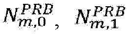
  • the corresponding PRB indexes may be respectively denoted as N m , 0 PRB , N m , 1 PRB .
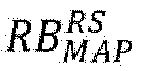
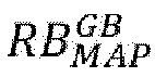
  • f MAP RB I MAP , RS MAP may represent a mapping of the set I MAP and the set RS MAP to a set including one or more RBs.
  • f MAP RB I MAP , RS MAP may be defined as one of the following:
  • f MAP RB I MAP , RS MAP may be different.
  • the start time of a transmission may not be arbitrary, but is limited to some discrete time points.
  • the start time can only be located at the start time of one slot, or at the start time of a particular symbol (e.g., the first SL symbol) in one slot, which greatly limits the flexibility of performing transmission in the unlicensed spectrum.
  • a cyclic prefix extension CPE
  • the start time of the symbol indexed as l ⁇ ⁇ 0, 1, ⁇ , N slot subframe , ⁇ N symb slot ⁇ 1 ⁇ in the subframe is t start , l ⁇
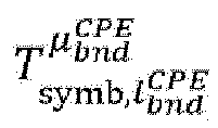
  • the symbol length (or referred to as the "symbol duration") is T symb , l ⁇
  • transmission e.g., denoted as TS l 0
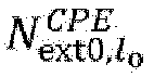
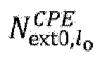
  • the CPE length T ext, l 0 may be defined in one of the following manners:
  • a set of all possible values of T ext, l o of the transmission TS l o (or referred to as "all allowed values of T ext, l o of the transmission TS l o " ) may be denoted as E ext , l 0 CPE .
  • the largest element in the set E ext , l 0 CPE may be denoted as T e xt,max, l o .
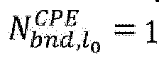
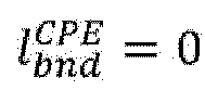
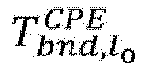
  • T ext,bnd, l o may be related to l 0 , or may be independent of l 0 .
  • T ext,bnd, l o may be related to ⁇ , or may be independent of ⁇ .
  • T ext,bnd, l o may be equal to one of the following:
  • Embodiment 1 of the present invention A method performed by a user equipment according to Embodiment 1 of the present invention will be described below with reference to FIG. 1 .
  • FIG. 1 shows a flowchart corresponding to the method performed by user equipment according to Embodiment 1 of the present invention.
  • the steps performed by user equipment include: step S101 and step S103.
  • step S101 information related to S-SS/PSBCH block transmission (or reception) is acquired and/or determined.
  • the "S-SS/PSBCH block” may also be referred to as “SL SSB” or "S-SSB”.
  • the "information related to S-SS/PSBCH block transmission (or reception)" may be configured in an SL BWP.
  • the SL BWP may include N RBset BWP RB sets respectively denoted as, for example, rs 0 BWP , rs 1 BWP , ⁇ ⁇ , rs N RBset BWP ⁇ 1 BWP , in ascending order of frequencies, where N RBset BWP may be an integer greater than or equal to 1.
  • N RBset BWP ⁇ 1 the lowest indexed common resource block (CRB) and the highest indexed CRB of rs i BWP may be respectively denoted as N i BWP , RS , start and N i BWP , RS , end .
  • the number of RBs of rs i BWP may be denoted as N i BWP , RS , size .
  • N i BWP , RS , size may be equal to N i BWP , RS , end ⁇ N i BWP , RS , start + 1 .
  • j ⁇ 0 , 1 , ⁇ , N GB BWP ⁇ 1 , gb j BWP may be used to separate the RB set rs j BWP and the RB set rs j + 1 BWP .
  • the lowest indexed CRB and the highest indexed CRB of gb j BWP may be respectively denoted as N j BWP , GB , start and N j BWP , GB , end .
  • the number of RBs may be denoted as N j BWP , GB , size .
  • N j BWP , GB , size may be equal to N j BWP , GB , end ⁇ N j BWP , GB , start + 1 .
  • the lowest indexed CRB of the SL BWP may be equal to N 0 BWP , RS , start .
  • 216 consecutive RBs are configured in the SL BWP (e.g., corresponding CRB indexes are respectively 0, 1, ..., 215), and the 216 RBs may be respectively located in the following three sets:
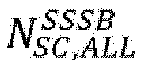
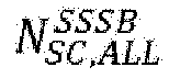
  • N SC , ALL SSSB may be a predefined or configured or pre-configured value, or may be determined by one or more predefined or configured or pre-configured values, or may be determined in another manner.
  • N SC , ALL SSSB 132 .
  • N SC , ALL SSSB is an integer multiple of 132.
  • N SC , ALL SSSB 240 .
  • N SC , ALL SSSB is an integer multiple of 240.
  • the N SC , ALL SSSB subcarriers may be respectively indexed as 0, 1, ⁇ , N SC , ALL SSSB ⁇ 1 in a certain order (e.g., in ascending order of center frequencies of the subcarriers).
  • the N SC , ALL SSSB subcarriers may be N SC , ALL SSSB consecutive subcarriers.
  • the N SC , ALL SSSB subcarriers may correspond to N SC , ALL SSSB consecutive subcarriers, starting from the first subcarrier of a certain PRB, in the SL BWP.
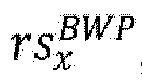
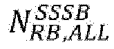
  • the N RB , ALL SSSB RBs may be in the same RB set (e.g., denoted as rs x BWP , wherein x ⁇ ⁇ 0, 1 , ⁇ , N RBset BWP ⁇ 1 ⁇ ).
  • indexes of the N RB , ALL SSSB RBs in the RB set rs x BWP may be respectively X 0 ⁇ N RB , ALL SSSB / 2 ⁇ ⁇ RB SSSB , X 0 ⁇ N RB , ALL SSSB 2 ⁇ 1 .
  • X 0 may be equal to N x BWP , RS , size / 2 .
  • ⁇ RB SSSB may be a predefined or configured or pre-configured value, or ⁇ RB SSSB may be related to N x BWP , RS , size and/or N RB , ALL SSSB (or N SC , ALL SSSB ) .
  • N RB , ALL SSSB 11
  • N x BWP , RS , size 106
  • X 0 53
  • ⁇ RB SSSB 10 .
  • the N SC , ALL SSSB subcarriers may be non-consecutive (or partially consecutive) subcarriers.
  • the N SC , ALL SSSB subcarriers may be subcarriers in a plurality of RBs in one or more interlaces.
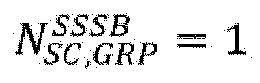
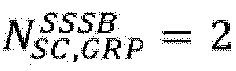
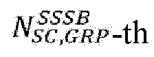
  • the N SC , ALL SSSB subcarriers may be divided into N SC , GRP SSSB subcarrier groups.
  • the N SC , GRP SSSB subcarrier groups may be respectively indexed as 0, 1, ⁇ , N SC , GRP SSSB ⁇ 1 in a certain order (e.g., in ascending order of indexes of interlaces in which the subcarriers in each subcarrier group are located, or in ascending order of the center frequencies of the subcarriers having the lowest center frequencies in respective subcarrier groups).
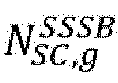
  • the number of subcarriers included in a subcarrier group g may be denoted as N SC , g SSSB .
  • the N SC , g SSSB subcarriers may be respectively indexed in a certain order (e.g., in ascending order of center frequencies of the subcarriers) as 0, 1, ..., N SC , g SSSB ⁇ 1 .
  • Each of the N SC , GRP SSSB subcarrier groups may consist of subcarriers in a plurality of RBs in the same interlace.
  • Each subcarrier group may correspond to a unique predefined or configured or pre-configured interlace. For example, if g 1 ⁇ 0 , 1 , ... , N SC , GRP SSSB ⁇ 1 , g 2 ⁇ 0 , 1 , ... , N SC , GRP SSSB ⁇ 1 and g 1 ⁇ g 2 , the subcarrier group g 1 may consist of subcarriers in a plurality of RBs in an interlace, and the subcarrier group g 2 may consist of subcarriers in a plurality of RBs in another interlace.
  • the plurality of RBs in each subcarrier group may be determined in a predefined or configured or pre-configured manner (e.g., a plurality of RBs with consecutive IRB numbers in an interlace may be determined according to a predefined or configured or pre-configured starting IRB in the corresponding interlace and a predefined or configured or pre-configured number of IRBs).
  • the CRB (or PRB) ranges corresponding to the subcarriers in any two of the N SC , GRP SSSB subcarrier groups may not overlap with each other.
  • the 72 subcarriers may consist of subcarriers in six CRBs with respective numbers of 0, 10, 20, 30, 40, and 50 in the interlace 0, and the corresponding CRB range may be denoted as [0, 50].
  • the 60 subcarriers may consist of subcarriers in five CRBs with respective numbers of 55, 65, 75, 85, and 95 in the interlace 5, and the corresponding CRB range may be denoted as [55, 95].
  • N SC , GRP SSSB ⁇ 1 , N SC , g SSSB subcarriers in the subcarrier group g may be consecutive subcarriers.
  • the N SC , g SSSB subcarriers may correspond to N SC , g SSSB consecutive subcarriers, starting from the first subcarrier of a certain PRB, in the SL BWP.
  • subcarrier group g may be non-consecutive (or partially consecutive) subcarriers.
  • all of the subcarriers in the first subcarrier group i.e., the subcarrier group 0
  • all of the subcarriers in the second subcarrier group i.e., the subcarrier group 1
  • all of the subcarriers in the N SC , GRP ⁇ th SSSB subcarrier group i.e., the subcarrier group N SC , GRP SSSB ⁇ 1
  • indexing may be performed in ascending order of indexes of corresponding subcarriers in the subcarrier group.
  • the subcarriers in the subcarrier group 0 are respectively indexed as 0, 1, ..., 131 in ascending order of the indexes thereof in the subcarrier group 0, and then the subcarriers in the subcarrier group 1 are respectively indexed as 132, 133, ..., 263 in ascending order of the indexes thereof in the subcarrier group 1.
  • a "basic subcarrier group" (e.g., the subcarrier group 0) may be predefined or configured or pre-configured in the N SC , GRP SSSB subcarrier groups.
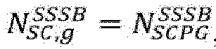
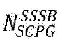
  • resource elements (REs) corresponding to the subcarriers in the basic subcarrier group may be respectively copied to REs corresponding to the subcarriers in each other subcarrier group (for example, for each other subcarrier group g, the REs respectively corresponding to the subcarriers 0, 1, ..., N SCPG SSSB ⁇ 1 in the basic subcarrier group are respectively copied to the REs respectively corresponding to the subcarriers 0, 1, ..., N SCPG SSSB ⁇ 1 in the subcarrier group g).
  • the S-SS/PSBCH block may be first mapped to REs corresponding to the subcarriers 0, 1, ..., 131 in the basic subcarrier group (e.g., the subcarrier group 0), then REs respectively corresponding to the subcarriers 0, 1, ..., 131 in the basic subcarrier group are respectively copied to REs respectively corresponding to the subcarriers 0, 1, ..., 131 in the subcarrier group 1, and then REs respectively corresponding to the subcarriers 0, 1, ..., 131 in the basic subcarrier group are respectively copied to REs corresponding to the subcarriers 0, 1, ..., 131 in the subcarrier group 2.
  • an “anchor subcarrier” may be determined in the N SC , ALL SSSB subcarriers.
  • the index of the anchor subcarrier in an S-SS/PSBCH block may be denoted as sc anc SSSB , where sc anc SSSB ⁇ 0 , 1 , ... , N SC , ALL SSSB ⁇ 1 .
  • sc anc SSSB N SC , ALL SSSB ⁇ 1 .
  • sc anc SSSB N SC , ALL SSSB / 2 .
  • sc anc SSSB N SCPG SSSB / 2 .
  • sc anc SSSB N SC , ALL SSSB / 2 .
  • the anchor subcarrier may be a predefined or configured or pre-configured subcarrier (e.g., indexed as sc g 0 , s 0 SSSB in the subcarrier group g 0 ) in a predefined or configured or pre-configured subcarrier group (e.g., indexed as g 0 ) in an S-SS/PSBCH block.
  • g 0 0.
  • g 0 corresponds to the basic subcarrier group.
  • sc g 0 , s 0 SSSB N SC , g 0 SSSB ⁇ 1 .
  • sc g 0 , s 0 SSSB 0 .
  • sc g 0 , s 0 SSSB N SC , g 0 SSSB / 2 .
  • SC g 0 , s 0 SSSB N SC , g 0 SSSB / 2 .
  • SC g 0 , s 0 SSSB N SC , g 0 SSSB / 2 .
  • the "information related to S-SS/PSBCH block transmission (or reception)" may include N freq SSSB "S-SS/PSBCH block frequency locations" (or referred to as “candidate S-SS/PSBCH block frequency locations").
  • Each "S-SS/PSBCH block frequency location” may be used to determine the frequency location of one S-SS/PSBCH block to be transmitted (or received) (e.g., determining the frequency location of each subcarrier in the S-SS/PSBCH block).
  • N freq SSSB may be a predefined or configured or pre-configured value, or may be determined according to one or more predefined or configured or pre-configured values.
  • N freq SSSB One or more of the following limitations may be applied to N freq SSSB :
  • the unit of the "S-SS/PSBCH block frequency location" may be Hz, or kHz, or MHz, or the like, and accordingly, the N freq SSSB S-SS/PSBCH block frequency locations may be respectively denoted as f 0 SSSB , f 1 SSSB , ... ... , f N freq SSSB ⁇ 1 SSSB in ascending order of frequencies.
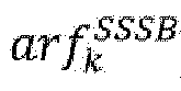
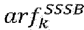
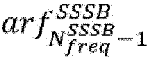
  • f k SSSB may correspond to an NR absolute radio frequency channel number (NR-ARFCN), denoted as, for example, arf k SSSB .
  • NR-ARFCN NR absolute radio frequency channel number
  • arf k SSSB may be a value in the integer range [0, 3279165].
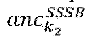
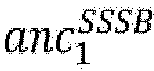
  • f k SSSB may correspond to an anchor subcarrier denoted as, for example, anc k SSSB in an S-SS/PSBCH block (or referred to as a "candidate S-SS/PSBCH block").
  • f k SSSB may correspond to the center frequency of the anchor subcarrier anc k SSSB , and the unit of the center frequency may be Hz, or kHz, or MHz, or the like.
  • the method for determining the subcarrier index of anc k 1 SSSB in the corresponding S-SS/PSBCH block may be the same as the method for determining the subcarrier index of anc k 2 SSSB in the corresponding S-SS/PSBCH block.
  • the subcarrier indexes of anc k 1 SSSB and anc k 2 SSSB in the respective corresponding S-SS/PSBCH blocks are both equal to N SC , ALL SSSB / 2 .
  • f k SSSB For k ⁇ 0 , 1 , ... , N freq SSSB ⁇ 1 , one or more of the following limitations may be applied to f k SSSB and/or the frequency location of the corresponding S-SS/PSBCH block:
  • One of f 0 SSSB or arf 0 SSSB , or anc 0 SSSB , f 1 SSSB or arf 1 SSSB , or anc 1 SSSB , ..., and f N freq SSSB ⁇ 1 SSSB or arf N freq SSSB ⁇ 1 SSSB , or anc N freq SSSB ⁇ 1 SSSB may be used to determine other N freq SSSB ⁇ 1 (for example, when N freq SSSB ⁇ 2 .
  • anc 0 SSSB may be configured or pre-configured via a higher-layer parameter (e.g., denoted as sl-SSBLocations0 ), and for k ⁇ 1 , ... , N freq SSSB ⁇ 1 , anc k SSSB may be determined according to anc 0 SSSB .
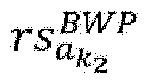
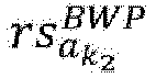
  • the subcarrier index of anc k SSSB in the RB set rs a k BWP may be equal to the subcarrier index of anc 0 SSSB in the RB set rs a 0 BWP .
  • One SL synchronization configuration may correspond to one or more time allocations for S-SS/PSBCH block transmission (or reception).
  • the indexes of the time allocation periods in one frame number period may be denoted as n TA ( n TA ⁇ ⁇ 0, 1, ..., N TAP - 1 ⁇ ).
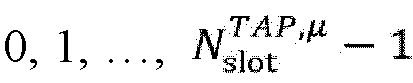
  • the slot indexes in one time allocation period may be respectively denoted as 0 , 1 , ... , N slot TAP , ⁇ ⁇ 1 , in chronological order, wherein N slot TAP , ⁇ may be equal to T TAP ⁇ N slot frame , ⁇ e . g . , 16 ⁇ 10 ⁇ 2 ⁇ .
  • N period SSSB S-SS/PSBCH block indexes may be present in one time allocation period, and are respectively denoted as, for example, 0 , 1 , ... , N period SSSB ⁇ 1 in chronological order.
  • the index (e.g., denoted as n period SSSB , wherein n period SSSB ⁇ 0 , 1 , ... , N slot TAP , ⁇ ⁇ 1 of the slot thereof in the time allocation period may be equal to N offset SSSB + N interval SSSB + 1 ⁇ b period SSSB , wherein N interval SSSB may be a predefined or configured or pre-configured slot interval, and N offset SSSB may be a predefined or configured or pre-configured slot offset.
  • f k SSSB (or arf k SSSB , or anc k SSSB , or rs a k BWP ) may be related to an S-SS/PSBCH block transmission (or reception) time (e.g., one or more of the following):
  • the index ( a k ) of the RB set ( rs a k BWP ) where f k SSSB is located may be defined as one or more of the following:
  • t may be n s ⁇ , or n s , f ⁇ , or n s , f , p ⁇ , or n period SSSB , or n TA , or b period SSSB .
  • step S103 the S-SS/PSBCH block transmission (or reception) is performed.
  • S-SS/PSBCH block(s) is detected and/or received according to the "information related to S-SS/PSBCH block transmission (or reception)".
  • S-SS/PSBCH block(s) is detected and/or received in a slot n period SSSB corresponding to an S-SS/PSBCH block index b period SSSB in a time allocation period in S-SS/PSBCH block frequency location(s) respectively corresponding to one or a plurality (e.g., denoted as N rcvd SSSB ) of f 0 SSSB (or arf 0 SSSB , or anc 0 SSSB ), f 1 SSSB (or arf 1 SSSB , or anc 1 SSSB ), ..., or f N freq SSSB ⁇ 1 SSSB (or arf N freq SSSB ⁇ 1 SSSB , or anc N freq SSSB ⁇ 1 SSSB ).
  • N rcvd SSSB may be a value in the integer range 1 N freq SSSB .
  • N rcvd SSSB 1 .
  • the value of N rcvd SSSB may relate to the capabilities of the UE.
  • S-SS/PSBCH block(s) is transmitted according to the "information related to S-SS/PSBCH block transmission (or reception)". Specifically, for example, in a slot n period SSSB corresponding to an S-SS/PSBCH block index b period SSSB in a time allocation period, N txd SSSB RB sets for transmitting the S-SS/PSBCH block are determined from rs a 0 BWP , rs a 1 BWP , ⁇ ⁇ , rs a N freq SSSB ⁇ 1 BWP and the S-SS/PSBCH block(s) is respectively transmitted in corresponding S-SS/PSBCH block frequency locations in the N txd SSSB RB sets.
  • N txd SSSB may be a value in the integer range 1 N freq SSSB .
  • N txd SSSB 1 .
  • the value of N txd SSSB may relate to the capabilities of
  • the N txd SSSB RB sets may be autonomously determined by the UE.
  • the N txd SSSB RB sets may be determined via random selection. For example, N txd SSSB RB sets for S-SS/PSBCH block transmission are randomly selected from rs a 0 BWP , rs a 1 BWP , ... ... , rs a N freq SSSB ⁇ 1 BWP .
  • N txd SSSB RB sets for S-SS/PSBCH block transmission are determined among the N accOK SSSB RB sets. For example, N txd SSSB RB sets for S-SS/PSBCH block transmission are randomly selected from the N accOK SSSB RB sets.
  • Embodiment 1 provided in the present invention is a method. More than one frequency location for an S-SS/PSBCH block is allowed to be configured, and the S-SS/PSBCH block corresponding to each frequency location is within a bandwidth of a unique RB set within an SL BWP, so that the probability that the S-SS/PSBCH block can still be transmitted when one or more channel access failures occur within the SL BWP is greatly increased, thereby improving the stability of a synchronization procedure of an SL link.
  • FIG. 2 is used to illustrate user equipment that can perform the method performed by user equipment described in detail above in the present invention as a variant embodiment.
  • FIG. 2 is a block diagram showing user equipment (UE) according to the present invention.
  • user equipment (UE) 20 includes a processor 201 and a memory 202.
  • the processor 201 may include, for example, a microprocessor, a microcontroller, an embedded processor, and the like.
  • the memory 202 may include, for example, a volatile memory (such as a random access memory (RAM)), a hard disk drive (HDD), a non-volatile memory (such as a flash memory), or other memories. etc.
  • the memory 202 has program instructions stored thereon. The instructions, when run by the processor 201, can perform the above method performed by user equipment described in detail in the present invention.
  • the method and related equipment according to the present invention have been described above in combination with preferred embodiments. It should be understood by those skilled in the art that the method shown above is only exemplary, and the above embodiments can be combined with one another as long as no contradiction arises.
  • the method of the present invention is not limited to the steps or sequences illustrated above.
  • the network node and user equipment shown above may include more modules, for example, modules that may be developed or developed in the future and that may be used for a base station, an Access and Mobility Management Function (AMF), a User Plane Function (UPF), a Mobility Management Entity (MME), a Serving Gateway (S-GW), or a UE.
  • AMF Access and Mobility Management Function
  • UPF User Plane Function
  • MME Mobility Management Entity
  • S-GW Serving Gateway
  • UE User Plane Function
  • Various identifiers shown above are only exemplary, and are not meant for limiting the present invention.
  • various components in the base station and user equipment in the above embodiments can be implemented by multiple devices, and these devices include, but are not limited to: an analog circuit device, a digital circuit device, a digital signal processing (DSP) circuit, a programmable processor, an application-specific integrated circuit (ASIC), a field-programmable gate array (FPGA), a complex programmable logic device (CPLD), and the like.
  • DSP digital signal processing
  • ASIC application-specific integrated circuit
  • FPGA field-programmable gate array
  • CPLD complex programmable logic device
  • the term “base station” may refer to a mobile communication data and/or control switching center having specific transmission power and a specific coverage area, and, for example, has functions such as resource allocation and scheduling, and data reception and transmission.
  • “User equipment” may refer to user mobile terminals, such as terminal devices that can communicate with a base station or a micro base station wirelessly, including a mobile phone, a laptop computer, and the like.
  • the embodiments of the present invention disclosed herein may be implemented on a computer program product.
  • the computer program product is a product provided with a computer-readable medium having computer program logic encoded thereon.
  • the computer program logic When executed on a computing device, the computer program logic provides related operations to implement the above technical solutions of the present invention.
  • the computer program logic When executed on at least one processor of a computing system, the computer program logic causes the processor to perform the operations (the method) described in the embodiments of the present invention.
  • Such setting of the present invention is typically provided as software, codes and/or other data structures provided or encoded on the computer-readable medium, e.g., an optical medium (e.g., compact disc read-only memory (CD-ROM)), a flexible disk or a hard disk and the like, or other media such as firmware or micro codes on one or more read-only memory (ROM) or random access memory (RAM) or programmable read-only memory (PROM) chips, or a downloadable software image, a shared database and the like in one or more modules.
  • Software or firmware or such configuration may be installed on a computing device such that one or more processors in the computing device perform the technical solutions described in the embodiments of the present invention.
  • each functional module or each feature of the base station device and the terminal device used in each of the above embodiments may be implemented or executed by circuits, which are usually one or more integrated circuits. Circuits designed to execute various functions described in this description may include general-purpose processors, digital signal processors (DSPs), application-specific integrated circuits (ASICs) or general-purpose integrated circuits, field-programmable gate arrays (FPGAs) or other programmable logic devices, discrete gates or transistor logic, or discrete hardware components, or any combination of the above.
  • the general-purpose processor may be a microprocessor, or the processor may be an existing processor, a controller, a microcontroller, or a state machine.
  • the aforementioned general-purpose processor or each circuit may be configured by a digital circuit or may be configured by a logic circuit. Furthermore, when advanced technology capable of replacing current integrated circuits emerges due to advances in semiconductor technology, the present invention can also use integrated circuits obtained using this advanced technology.

Landscapes

  • Engineering & Computer Science (AREA)
  • Computer Networks & Wireless Communication (AREA)
  • Signal Processing (AREA)
  • Mobile Radio Communication Systems (AREA)

Abstract

Provided in the present invention are a method performed by user equipment, and user equipment. The method performed by user equipment includes: determining one or more frequency locations within one SL BWP for S-SS/PSBCH block reception, wherein each frequency location corresponds to a center frequency of one subcarrier in one S-SS/PSBCH block, and a bandwidth of the S-SS/PSBCH block is within a bandwidth of a unique RB set within the SL BWP; and receiving the S-SS/PSBCH block in part or all of the one or more frequency locations.

Description

    TECHNICAL FIELD
  • The present invention relates to a method performed by user equipment, and user equipment.
  • BACKGROUND ART
  • In a wireless communication system, UEs (user equipment) can perform sidelink (SL) communication with each other. The SL communication may include general device-to-device (D2D) communication, vehicle-to-vehicle (V2V) communication, vehicle-to-everything (V2X) communication, and the like.
  • In order to support SL communication on a licensed spectrum and/or an unlicensed spectrum, a series of issues need to be solved, such as channel access mechanisms, physical layer channel and/or signal structures, physical layer procedures (e.g., a synchronization procedure, and feedback and/or a determination mechanism), resource allocation and/or management, and coexistence with other systems.
  • Prior Art Documents Non-Patent Documents
    • Non-Patent Document 1: RP-152293, New WI proposal: Support for V2V services based on LTE sidelink, 3GPP TSG RAN Meeting#70
    • Non-Patent Document 2: RP-170798, New WID on 3GPP V2X Phase 2, 3GPP TSG RAN Meeting#75
    • Non-Patent Document 3: RP-170855, New WID on New Radio Access Technology, 3GPP TSG RAN Meeting#75
    • Non-Patent Document 4: RP-190766, New WID on 5G V2X with NR sidelink, 3GPP TSG RAN Meeting#83
    • Non-Patent Document 5: RP-201385, WID revision: NR sidelink enhancement, 3GPP TSG RAN Meeting#88e
    • Non-Patent Document 6: RP-213678, New WID on NR sidelink evolution, 3GPP TSG RAN Meeting#94e
    SUMMARY OF THE INVENTION
  • In order to address at least part of the aforementioned issues, provided in the present invention are a method performed by user equipment, and user equipment. More than one frequency location for an S-SS/PSBCH block is allowed to be configured, and the S-SS/PSBCH block corresponding to each frequency location is within a bandwidth of a unique RB set within an SL BWP, so that the probability that the S-SS/PSBCH block can still be transmitted when one or more channel access failures occur within the SL BWP is greatly increased, thereby improving the stability of a synchronization procedure of an SL link.
  • According to the present invention, a method performed by user equipment is provided. The method is characterized by comprising: determining one or more frequency locations within one SL BWP for S-SS/PSBCH block reception, wherein each frequency location corresponds to a center frequency of one subcarrier in one S-SS/PSBCH block, and a bandwidth of the S-SS/PSBCH block is within a bandwidth of a unique RB set within the SL BWP; and receiving the S-SS/PSBCH block in part or all of the one or more frequency locations.
  • Furthermore, according to the present invention, provided is user equipment, comprising: a processor; and a memory, having instructions stored therein, wherein the instructions, when run by the processor, perform the above method.
  • Therefore, provided in the present invention is a method. More than one frequency location for an S-SS/PSBCH block is allowed to be configured, and the S-SS/PSBCH block corresponding to each frequency location is within a bandwidth of a unique RB set within an SL BWP, so that the probability that the S-SS/PSBCH block can still be transmitted when one or more channel access failures occur within the SL BWP is greatly increased, thereby improving the stability of a synchronization procedure of an SL link.
  • BRIEF DESCRIPTION OF THE DRAWINGS
  • The above and other features of the present invention will be more apparent from the following detailed description in combination with the accompanying drawings, in which:
    • FIG. 1 shows a flowchart corresponding to the method performed by user equipment according to Embodiment 1 of the present invention.
    • FIG. 2 is a block diagram of user equipment (UE) according to the present invention.
    DETAILED DESCRIPTION OF PREFERRED EMBODIMENTS
  • The following describes the present invention in detail with reference to the accompanying drawings and specific embodiments. It should be noted that the present invention should not be limited to the specific embodiments described below. In addition, detailed descriptions of well-known technologies not directly related to the present invention are omitted for the sake of brevity, in order to avoid obscuring the understanding of the present invention.
  • In the following description, 5G (or referred to as "New Radio" (NR) or 5G NR) wireless communication system specifications and later evolved versions thereof (e.g., 5G Advanced) formulated by the 3rd Generation Partnership Project (3GPP) are used as exemplary application environments to specifically describe a plurality of embodiments according to the present invention. However, it is to be noted that the present invention is not limited to the following embodiments, but is applicable to many other wireless communication systems, such as wireless communication systems later than 5G, or such as 4G mobile communication systems earlier than 5G, e.g., Long Term Evolution (LTE), LTE-Advanced, LTE-Advanced Pro, etc.
  • The terms given in the present invention may be named differently in different wireless communication systems, but unified terms are used in the present invention. When applied to a specific system, the terms may be replaced with terms used in the corresponding system.
  • Unless otherwise specified, in all embodiments and implementations of the present invention:
    • ● "Higher layer(s)" or "upper layer(s)" may refer to one or more protocol layers or protocol sub-layers above a given reference protocol layer or reference protocol sublayer (e.g., a physical layer) in a given protocol stack. For example, for a physical layer, a "higher layer" may refer to a Medium Access Control (MAC) layer, a Radio Link Control (RLC) layer, a Packet Data Convergence Protocol (PDCP) layer, a PC5 Radio Resource Control (RRC) layer, a PC5-S layer, an RRC layer, a Vehicle-to-everything (V2X) layer, an application layer, a V2X application layer, or the like. Unless otherwise specified, the reference protocol layer refers to a physical layer.
    • ● "Configure" may mean that a protocol layer (e.g., RRC layer) entity in a communication node (e.g., UE, or an eNB, or a gNB) provides configuration information to another protocol layer (e.g., physical layer) entity.
    • ● "Configuration" may mean that a communication node provides configuration information to another communication node (for example, a base station transmits RRC signaling to UE, which includes the configuration information, and as another example, UE-A transmits PC5-RRC signaling to UE-B, which includes the configuration information).
    • ● "Configure" may include "pre-configure". "Pre-configure" may mean that corresponding configuration information is pre-configured in a specific storage location in the UE, or corresponding configuration information is pre-configured in a specific accessible storage location in the UE.
    • ● The constant Tc may be defined as: Tc = 1/(Δfmax · Nf), where Δfmax = 480 · 103 Hz, and Nf = 4096.
    • ● The constant κ may be defined as: x = Ts /Tc = 64, where Ts = 1/(Δfref · Nf, ref ), Δfref = 15 · 103 Hz, and Nf, ref = 2048.
    • µ may represent a subcarrier spacing configuration, for example µ = 0. Δf may represent a corresponding subcarrier spacing (SCS), and for example µ = 0 corresponds to Δf = 15 kHz.
    • ● "Symbol" may refer to an orthogonal frequency division multiplexing (OFDM) symbol.
    • N slot subframe , μ
      Figure imgb0001
      may represent the number of slots in each subframe.
    • N symb slot
      Figure imgb0002
      may represent the number of symbols in each slot.
    • ● One resource may correspond to one or more of the following:
      • ■ One or more parameters in the time domain. For example, a starting symbol of the resource, or a starting slot of the resource, or the number of symbols occupied by the resource, or the number of slots occupied by the resource.
      • ■ One or more parameters in the frequency domain. For example, a starting subchannel of the resource, or a starting resource block (RB) of the resource, or a starting subcarrier of the resource, or the number of sub-channels occupied by the resource, or the number of RBs occupied by the resource, or the number of subcarriers occupied by the resource.
      • ■ One or more parameters in the code domain. For example, a cyclic shift value corresponding to the resource or a corresponding cyclic shift index. As another example, a cyclic shift pair value corresponding to the resource or a corresponding cyclic shift pair index.
      • ■ One or more parameters in the spatial domain. For example, a layer corresponding to the resource, where a "layer" may refer to a multiple input multiple output (MIMO) layer.
    • ● An "RB" may refer to a virtual resource block (VRB), or a physical resource block (PRB), or a common resource block (CRB), or an interlaced resource block (IRB).
    • ● "Number" and "index" are interchangeable. For example, the number of an RB may also be referred to as the index of the RB. As another example, "an RB being numbered as 0" may also be expressed as "an RB being indexed as 0".
    • ● The numbering of elements in a sequence (or an array, or a list, or an ordered set, or the like) may start from 0. For example, the first RB of an RB set may be referred to as RB 0 of the RB set.
    • ● An object (e.g., a subcarrier, a slot, a cyclic shift, etc.) may be represented by the index thereof. For example, a CRB numbered as 0 may be referred to as CRB 0.
    • ● If a corresponding number is not specified when a type of object is mentioned, the number of the objects may be one or multiple. For example, in the expression "performing transmission on one channel", the "transmission(s) " may correspond to one transmission, or a plurality of transmissions.
    • ● Δ(x 1, x 2) may represent an offset between x 1 and x 2, where x 1 and x 2 may be two parameters (or variables) that can be compared, or two possible values of one parameter (or variable) (e.g., x 1 and x 2 may be two slots, or two subframes, or two frames, or two subcarriers, or two RBs, or two sub-channels, or the like).
    • • Δ(x 1, x 2) may be equal to x 2 - x 1. For example, a CRB set is denoted as A CRB ref = a 0 ref = 5 , a 1 ref = 15 , a 2 ref = 25 , a 3 ref = 35 , a 4 ref = 45 , x 1 = a 0 ref
      Figure imgb0003
      , and x 2 = a 3 ref
      Figure imgb0004
      , so that Δ(x 1, x 2) may be equal to a 3 ref a 0 ref = 35 5 = 30
      Figure imgb0005
      .
    • ● Δ(x 1, x 2) may be equal to idx(x 2) - idx(x 1), where idx(x 1) and idx(x 2) are respectively indexes of elements in the same set corresponding to x 1 and x 2. For example, the CRB set is denoted as A CRB ref = a 0 ref = 5 , a 1 ref = 15 , a 2 ref = 25 , a 3 ref = 35
      Figure imgb0006
      , a 4 ref = 45 , x 1 = a 0 ref
      Figure imgb0007
      , and x 2 = a 3 ref
      Figure imgb0008
      , so that Δ(x1, x 2) may be equal to 3 - 0 = 3.
    • ● An "offset between x 1 and x 2" may also be referred to as an offset of x 2 with respect to x 1 or an offset of x 2 relative to x 1.
    • ● An "offset between x 1 and x 2" may also be referred to as an offset from x 1 to x 2.
    • ● Where applicable, if Δ(x 1, x 2) = D, x 2 may be denoted as x 2 = ADD(x1, D).
    • ● Where applicable, if Δ(x1, x 2) = D, x 1 may be denoted as x 1 = SUBTRACT(x2, D).
    • ● An offset between two subcarriers may refer to an offset between center frequencies of the two subcarriers.
    • ● A modulo operation may be defined as ra mod N, where
      • r is a remainder.
      • a = N × q + r, where q = a / N
        Figure imgb0009
        . q may be referred to as an integer quotient of a and N.
      • ■ 0 ≤ r < |N|.
    • ● The unit of microseconds may be denoted as µs or us.
    • ● A transmission that has not yet begun to be performed (e.g., before an intended start time of the transmission is reached) may be referred to as an "intended transmission".
    • ● A "sensing slot duration" may represent a duration of a corresponding sensing slot, or the sensing slot itself.
    • ● A "sensing slot" may represent the sensing slot itself, or a duration of the sensing slot.
    • ● Where applicable, "power detection" may be referred to as "energy detection", and correspondingly, "detected power" may be referred to as "detected energy". A "power detection threshold" may be referred to as an "energy detection threshold".
    • ● An "SL slot" may refer to a slot in which an SL resource is configured or pre-configured. The "SL resource" may not include a resource used for a synchronization procedure (for example, a resource for transmitting an S-SS/Physical Sidelink Broadcast CHannel or Sidelink-Synchronization Signal/Physical Sidelink Broadcast CHannel (S-SS/PSBCH) block), or may include a resource used for a synchronization procedure.
    • ● An "SL slot" may refer to a slot that belongs to a certain SL resource pool.
    • ● An SL symbol set in an SL slot may be denoted as L SL = l 0 SL , l 1 SL , , l N length SL 1 SL
      Figure imgb0010
      , where l 0 SL , l 1 SL , , l N length SL 1 SL
      Figure imgb0011
      respectively represent indexes of corresponding symbols in the slot, where l 0 SL = l start SL , l 1 SL = l start SL + 1 ,
      Figure imgb0012
      , l N length SL 1 SL = l start SL + N length SL 1
      Figure imgb0013
      , where l start SL
      Figure imgb0014
      is the index of the first SL symbol in the slot (for example, configured via the parameter sl-StartSymbol-r16), and N length SL
      Figure imgb0015
      is the number of SL symbols in the slot (for example, configured via the parameter sl-LengthSymbols-r16).
    • ● An SL transmission of multiplexing a physical sidelink shared channel (PSSCH) and a physical sidelink control channel (PSCCH) associated therewith in the same resource may be referred to as a "PSCCH/PSSCH transmission".
    • ● The "first SL symbol" (or referred to as "first symbol") in resource allocation (or referred to as "sidelink allocation") corresponding to a PSCCH/PSSCH transmission (or a PSCCH transmission therein, or a PSSCH transmission therein) may be a symbol l 0 SL
      Figure imgb0016
      or a symbol l 1 SL
      Figure imgb0017
      in an SL slot (T SL, 0) corresponding to the resource allocation. For example, when it is explicitly indicated that the resource allocation includes a "duplicated symbol" (i.e., the symbol l 0 SL
      Figure imgb0018
      ) in the corresponding PSCCH and/or PSSCH, the "first SL symbol" may refer to the symbol l 0 SL
      Figure imgb0019
      . As another example, when it is not explicitly indicated that the resource allocation includes a "duplicated symbol" in the corresponding PSCCH and/or PSSCH, the "first SL symbol" may refer to the symbol l 1 SL
      Figure imgb0020
      . As another example, when physical resource mapping is performed for the PSCCH transmission and/or the PSSCH transmission (e.g., before a resource element in the symbol l 1 SL
      Figure imgb0021
      in the PSCCH/PSSCH transmission, or the corresponding PSCCH transmission, or the corresponding PSSCH transmission is copied to the symbol l 0 SL
      Figure imgb0022
      ), or before physical resource mapping is performed for the corresponding PSCCH transmission and/or PSSCH transmission in the PSCCH/PSSCH transmission, the "first SL symbol" may refer to the symbol l 1 SL
      Figure imgb0023
      . As another example, when a cyclic prefix extension (CPE) corresponding to the PSCCH/PSSCH transmission, or the corresponding PSCCH transmission, or the corresponding PSSCH transmission is determined, the "first SL symbol" may refer to the symbol l 0 SL
      Figure imgb0024
      . As another example, when it is determined that a resource is configured or allocated for the PSCCH/PSSCH transmission, or the corresponding PSCCH transmission, or the corresponding PSSCH transmission, the "first SL symbol" may refer to the symbol l 1 SL
      Figure imgb0025
      .
    • ● The "first SL symbol" (or referred to as "first symbol") in a PSCCH/PSSCH transmission (or a corresponding PSCCH transmission, or a corresponding PSSCH transmission) may be the "first SL symbol" in resource allocation corresponding to the transmission.
    • ● "A subcarrier is in an SL BWP (or an RB set, or a guard band)" may mean one of the following:
      • ■ The center frequency of the subcarrier is in the bandwidth of the SL BWP (or the RB set, or the guard band).
      • ■ The bandwidth of the subcarrier is in the bandwidth of the SL BWP (or the RB set, or the guard band).
      • ■ The subcarrier is a subcarrier in the SL BWP (or the RB set, or the guard band).
    • ● "A subcarrier is not in an SL BWP (or an RB set, or a guard band)" may mean one of the following:
      • ■ The center frequency of the subcarrier is not in the bandwidth of the SL BWP (or the RB set, or the guard band).
      • ■ The bandwidth of the subcarrier is not in the bandwidth of the SL BWP (or the RB set, or the guard band).
      • ■ The subcarrier is not a subcarrier in the SL BWP (or the RB set, or the guard band).
    • ● "An S-SS/PSBCH block is in an SL BWP (or an RB set, or a guard band)" may mean one of the following:
      • ■ The bandwidth of the S-SS/PSBCH block is in the bandwidth of the SL BWP (or the RB set, or the guard band).
      • ■ All subcarriers of the S-SS/PSBCH block are in the SL BWP (or the RB set, or the guard band). For example, "a subcarrier is in an SL BWP (or an RB set, or a guard band)" may be respectively applied to each of the subcarriers.
      • ■ All subcarriers of the S-SS/PSBCH block are subcarriers in the SL BWP (or the RB set, or the guard band).
    • ● "An S-SS/PSBCH block is not in an SL BWP (or an RB set, or a guard band)" may mean one of the following:
      • ■ No part of the bandwidth of the S-SS/PSBCH block is in the bandwidth of the SL BWP (or the RB set, or the guard band).
      • ■ None of subcarriers of the S-SS/PSBCH block is in the SL BWP (or the RB set, or the guard band). For example, for any subcarrier of the S-SS/PSBCH block, the expression "the subcarrier is in the SL BWP (or the RB set, or the guard band)" is false.
      • ■ None of subcarriers of the S-SS/PSBCH block is a subcarrier in the SL BWP (or the RB set, or the guard band).
    • ● In the time domain, a "frame" (or referred to as a "radio frame") may be a system frame or a direct frame. A frame number period (e.g., denoted as TFNP ) may be a predefined or configured or pre-configured value, e.g., TFNP = 1024 frames. The duration of each frame may be Tf = 10 milliseconds, which may include 10 subframes, where the duration of each subframe is Tsf = 1 millisecond. Each subframe may include N slot subframe , μ
      Figure imgb0026
      slots, e.g., N slot subframe , μ = 2 μ
      Figure imgb0027
      . The index of a slot in a subframe may be denoted as n s μ n s μ 0 , 1 , , N slot subframe , μ 1
      Figure imgb0028
      . The index of a slot in a frame may be denoted as n s , f μ n s , f μ 0 , 1 , , N slot frame , μ 1
      Figure imgb0029
      where N slot frame , μ
      Figure imgb0030
      may be equal to 10 · 2 µ . A slot index in a frame number period may be denoted as n s , f , p μ n s , f , p μ 0 , 1 , , N slot FNP , μ 1
      Figure imgb0031
      , where N slot FNP , μ
      Figure imgb0032
      may be equal to T FNP N slot frame , μ
      Figure imgb0033
      (e.g., 1024 · (10 · 2 µ )).
  • 5G (or referred to as new radio (NR)) can operate in both a licensed spectrum (e.g., 2010 MHz to 2025 MHz) and an unlicensed spectrum (e.g., part or all of 5150 MHz to 5925 MHz, part or all of 5925 MHz to 7125 MHz, and part or all of 5925 MHz to 6425 MHz).
  • When 5G operates in an unlicensed spectrum, a 5G-capable communication node (or referred to as a "node", such as a base station or UE) may perform a "channel access procedure" for a "channel" (or "shared-spectrum channel"). One channel may correspond to one set consisting of several consecutive resource blocks (RBs). An operation performed on one or more shared spectrum channels may be referred to as an "operation with shared spectrum channel access". In contrast, an operation on a licensed spectrum may be referred to as an "operation without shared spectrum channel access".
  • One channel may correspond to one carrier, or a part of one carrier. For example, one channel may correspond to one carrier of a 20 MHz bandwidth. As another example, one channel may correspond to the lower 20 MHz part in one 40 MHz bandwidth carrier, and another channel may correspond to the higher 20 MHz part in the same carrier.
  • A channel access procedure may be used to assess whether a channel can be used to perform one or more transmissions (or referred to as "assessing whether one or more transmissions can be performed on a channel"), and the assessment operation may be referred to as clear channel assessment (CCA). Such a mechanism of performing CCA before using a channel may be referred to as Listen Before Talk (LBT).
  • In a channel access procedure, the state of a channel (e.g., as a result or an output of the channel access procedure) may be determined on the basis of a "sensing" operation performed on the channel. For example, the "clear" channel state may indicate a channel access success, or indicate that a corresponding channel is available, or indicate that one or more transmissions may be performed on the channel. As another example, the "busy" channel state may indicate a channel access failure, or indicate that a corresponding channel is unavailable, or indicate that no transmission can be performed on the channel). Specifically, for example, if a sensing result of the channel in sensing slot durations in a "defer duration" is clear, and sensing results in the immediately following N consecutive additional sensing slot duration(s) are all clear, the sensing result of the channel may be determined to be clear. N may be an integer greater than or equal to zero. A sensing slot duration (e.g., denoted as Tsl ) may be a predefined or configured or pre-configured value, e.g., Tsl = 9 us. A defer duration (e.g., denoted as Td ) may consist of a period of time having the length Tf and the immediately following mp' consecutive sensing slots, where Tf may be a predefined or configured or pre-configured value (e.g., Tf = 16 us), and mp' may be an integer greater than zero. The period of time having the length Tf may start with a sensing slot.
  • Within a sensing slot duration, if a duration in which power (e.g., denoted as Xdetected ) detected on a channel is less than (or, less than or equal to) a power detection threshold (e.g., denoted as Xthresh ) is at least Tsl, thresh , it can be considered that the channel is clear within the sensing slot duration, or otherwise, it can be considered that the channel is busy within the sensing slot duration. Tsl, thresh may be a predefined or configured or pre-configured value, e.g., Tsl, thresh = 4 us.
  • If a corresponding channel cannot be accessed before a start time of an intended transmission (e.g., before the first symbol corresponding to the transmission) (e.g., the channel cannot be accessed because the state of the channel is "busy"), it can be considered that a "channel access failure" occurs, which may be alternatively referred to as an "LBT failure" where applicable.
  • A transmission performed on a corresponding channel after a channel access procedure is performed may be referred to as "channel occupancy" (CO), and a corresponding duration may be referred to as a "channel occupancy time" (COT). A COT may be shared between one or more communication nodes, and accordingly, the time corresponding to the COT may include a time for which the one or more communication nodes perform transmissions on respective channels, and a time corresponding to a transmission gap between the transmissions (e.g., when the duration of the transmission gap is less than or equal to 25 us).
  • The channel access procedures may be classified into a plurality of types according to usage, applicable scenarios, etc. For example, if a time span of a sensing slot in which the sensing result is clear before transmission is performed is denoted as T last , intvl sns , T last , intvl sns
    Figure imgb0034
    is random in "channel access procedure type 1". In "channel access procedure type 2", T last , intvl sns
    Figure imgb0035
    is deterministic. Channel access procedure type 1 may be used for a non-shared COT or a shared COT. Channel access procedure type 2 may be used to perform channel access in a COT shared by one other communication node.
  • Channel access procedure type 2 may be divided, according to features of T last , intvl sns
    Figure imgb0036
    , into a plurality of sub-types, for example, one or more of the following:
    • ● Channel access procedure type 2A, where T last , intvl sns 25 us
      Figure imgb0037
      , or T last , intvl sns >
      Figure imgb0038
      25 us, or T last , intvl sns = 25 us
      Figure imgb0039
      . This is applicable to a case in which a gap (e.g., denoted as T gap tx
      Figure imgb0040
      ) between a corresponding transmission and an immediately preceding transmission satisfies a certain condition, for example T gap tx 25 us
      Figure imgb0041
      , or T gap tx > 25 us
      Figure imgb0042
      , or T gap tx = 25 us
      Figure imgb0043
      .
    • ● Channel access procedure type 2B, where T last , intvl sns = 16 us
      Figure imgb0044
      , or 16 us T last , intvl sns < 25 us
      Figure imgb0045
      , or 16 16 us T last , intvl sns 25 us
      Figure imgb0046
      , or 16 us < T last , intvl sns 25 us
      Figure imgb0047
      , or 16 us < T last , intvl sns < 25 us
      Figure imgb0048
      . This is applicable to a case in which T gap tx
      Figure imgb0049
      satisfies a certain condition, for example T gap tx = 16 us
      Figure imgb0050
      , or 16 us T gap tx < 25 us
      Figure imgb0051
      , or 16 us T gap tx 25 us
      Figure imgb0052
      , or 16 us < T gap tx 25 us
      Figure imgb0053
      , or 16 us < T gap tx < 25 us
      Figure imgb0054
      .
    • ● Channel access procedure type 2C, where sensing is not performed on a corresponding channel before transmission is performed (e.g., this may correspond to T last , intvl sns = 0 us
      Figure imgb0055
      ). This is applicable to a case in which T gap tx
      Figure imgb0056
      satisfies a certain condition, for example T gap tx < 16 us
      Figure imgb0057
      , or T gap tx 16 us
      Figure imgb0058
      .
  • A "multi-channel access procedure" refers to one or more channel access procedures that may be performed (e.g., performed in parallel) for performing one or more transmissions (e.g., multiple simultaneous transmissions) on a plurality of channels (e.g., a channel set corresponding thereto is denoted as CHacc ). The "one or more channel access procedures" may be channel access procedures respectively performed on channels in a "target sensing channel set" (e.g., denoted as CHsns = {ch 0, ch 1, ..., chQ - 1 }, where Q may be an integer greater than or equal to 1). The set CHsns may be equal to the set CHacc, or otherwise defined (e.g., if no guard band is configured on the carrier on which the channel in the set CHacc is located, the set CHsns may be equal to the set of all channels on the carrier). Specifically, for example, a channel access procedure may be respectively performed on each channel in the set CHsns (e.g., according to channel access procedure type 1), and whether the one or more transmissions can be performed may be determined according to a corresponding result (e.g., for each of the one or more transmissions, the transmission can be performed if access results of all channels corresponding to the transmission are clear). As another example, a channel chj may be selected (e.g., uniformly, randomly) from the set CHsns and channel access procedure type 1 may be performed thereon, while channel access procedure type 2 (e.g., channel access procedure type 2A, or channel access procedure type 2B, or channel access procedure type 2C) or another channel access procedure that is not channel access procedure type 1 may be performed on each of the other channels in the set CHsns, and whether the one or more transmissions can be performed is determined according to corresponding results.
  • For an unlicensed spectrum, a set of available resource blocks in a channel may be referred to as an "RB set". In a carrier (e.g., denoted as c), there may be N C RBset N C RBset 1
    Figure imgb0059
    RB sets respectively denoted as, for example, rs 0, rs 1, ······, rs N C RBset 1
    Figure imgb0060
    . For i 0 , 1 , , N C RBset 1
    Figure imgb0061
    , the lowest indexed common resource block (CRB) and the highest indexed CRB of rsi may be respectively denoted as N i RS , start
    Figure imgb0062
    , N i RS , end
    Figure imgb0063
    . The number of RBs of rsi may be denoted as N i RS , size
    Figure imgb0064
    , where N i RS , size
    Figure imgb0065
    may be equal to N i RS , end N i RS , start + 1
    Figure imgb0066
    . In addition, optionally, N C GB = N C RBset 1
    Figure imgb0067
    guard bands (or referred to as "intra-cell guard bands") for separating the N C RBset
    Figure imgb0068
    RB sets may be present in the carrier, and are respectively denoted as, for example, gb 0 , gb 1 , , gb N C GB 1
    Figure imgb0069
    . For j 0 , 1 , , N C GB 1
    Figure imgb0070
    , the lowest indexed CRB and the highest indexed CRB of gbj may be respectively denoted as N j GB , start
    Figure imgb0071
    and N j GB , end
    Figure imgb0072
    . The number of RBs of gbj may be denoted as N j GB , size
    Figure imgb0073
    , where N j GB , size
    Figure imgb0074
    may be equal to N j GB , end N j GB , start + 1
    Figure imgb0075
    , and gbj may be used to separate the RB set rsj and the RB set rs j + 1. For example, in a 40 MHz bandwidth carrier, for a 15 kHz SCS, there may be 216 consecutive RBs (e.g., CRB indexes thereof are respectively denoted as 0, 1, ..., 215), and the 216 RBs may be divided into three subsets, respectively corresponding to one RB set rs 0 ( N 0 RS , start = 0 , N 0 RS , end = 104 , N 0 RS , size = 105
    Figure imgb0076
    ), one guard band gb 0 ( N 0 GB , start = 105 , N 0 GB , end = 110 , N 0 GB , size = 6
    Figure imgb0077
    ), and one RB set rs 1 ( N 1 RS , start = 111 , N 1 RS , end = 215 , N 1 RS , size = 105
    Figure imgb0078
    ).
  • A set consisting of the N C RBset
    Figure imgb0079
    RB sets may be denoted as RSC = {rs 0 , rs 1, ..., rs N C RBset 1
    Figure imgb0080
    . For i 0 , 1 , , N C RBset 2
    Figure imgb0081
    there may be zero or one guard band between two adjacent RB sets (rsi and rs i +1). The set consisting of the N C GB
    Figure imgb0082
    guard bands may be denoted as GB C = gb 0 , gb 1 , , gb N C GB 1
    Figure imgb0083
    . For j 0 , 1 , , N C GB 1
    Figure imgb0084
    , if gbj is an empty set, it may be considered that no corresponding guard band is present. For j = 0 , 1 , , N C GB 1
    Figure imgb0085
    , if each gbj is an empty set, it may be considered that there is no guard band between the RB sets of the carrier c. N C BWP N C BWP 1
    Figure imgb0086
    bandwidth parts (BWPs) may be configured in the carrier c, and are respectively denoted as, for example, bwp 0 , bwp 1 , , bwp N C BWP 1
    Figure imgb0087
    . For k ∈ {0, 1, , N C BWP 1
    Figure imgb0088
    }, bWPk may correspond to N BWP , k RBset N BWP , k RBset N C RBset
    Figure imgb0089
    RB sets respectively denoted as, for example, rs a k , 0 , rs a k , 1 , , rs a k , N BWP , k RBset 1
    Figure imgb0090
    . For l ∈, {0, 1, ..., N BWP , k RBset 1
    Figure imgb0091
    }, rsak,l is an element in the set RSC, and a k , 0 < a k , 1 < < a k , N BWP , k RBset 1
    Figure imgb0092
    . The lowest indexed CRB (e.g., denoted as N BWP , k start
    Figure imgb0093
    ) of bwpk may be equal to N a k , o RS , start
    Figure imgb0094
    , and the number of RBs of bwpk (e.g., denoted as N BWP , k size
    Figure imgb0095
    ) may be equal to N a k , N BWP , k RBset 1 RS , end N a k , o RS , start + 1
    Figure imgb0096
    . The N BWP , k RBset
    Figure imgb0097
    RB sets may be N BWP , k RBset
    Figure imgb0098
    consecutive RB sets. For example, for l 1 , , N BWP , k RBset 1
    Figure imgb0099
    , ak, l = a k, 0 + l. For convenience, when no ambiguity is caused (e.g., in an operation involving only one BWP), N BWP , k RBset
    Figure imgb0100
    may be denoted as N BWP RBset
    Figure imgb0101
    , and rs a k , 0 , rs a k , 1 , , rs a k , N BWP , k RBset 1
    Figure imgb0102
    , may be respectively denoted as rs a 0 , rs a 1 , ·····, rs a N BWP RBset 1
    Figure imgb0103
    . A set consisting of the N BWP RBset
    Figure imgb0104
    RB sets may be denoted as RSBWP = {rs a 0 , rs a 1 , , rs a N BWP RBset 1
    Figure imgb0105
    }. The set RSBWP may be equal to the set RSC or equal to a subset of the set RSC.
  • For the unlicensed spectrum, in order to ensure fair channel sharing between different communication nodes, a certain restriction may be imposed on the power spectral density (PSD) and/or occupied channel bandwidth (OCB) of signal transmission. For example, the maximum PSD cannot exceed 10 dBm/MHz. As another example, when a channel is used, the bandwidth containing 99% of the transmission power must be greater than or equal to a certain percentage (e.g., 80%) of the nominal channel bandwidth. The restriction (if any) may be made and enforced by regulatory authorities. The restrictions (if any) on the PSD and/or the OCB may be different in different countries or regions.
  • To meet the restriction on the OCB, one radio transmission may correspond to one or more "interlaces". For example, MINT (MINT ≥ 1) interlaces may be defined, and the corresponding interlace set is IALL = {int 0, int 1, ..., intMINT-1 }. For m ∈ {0, 1, ..., MINT - 1}, the interlace intm may correspond to the CRB set {m, MINT + m, 2MINT + m, 3MINT + m, ...}. MINT may be a predefined or configured or pre-configured value.
  • The value of MINT may be related to a subcarrier spacing configuration µ (e.g., for µ = 0, MINT = 10, and for µ = 1, MINT = 5).
  • For the same subcarrier spacing configuration µ, different "interlaces" may be defined for different purposes (e.g., different types of SL transmissions). For example, for the same subcarrier spacing configuration µ, one value of MINT is defined for S-SS/PSBCH transmission, and another value of MINT is defined for PSCCH/PSSCH transmission and/or PSFCH transmission. For example, for the same subcarrier spacing configuration µ, one value of MINT is defined for S-SS/PSBCH transmission, and no interlace is defined for PSCCH/PSSCH transmission and/or PSFCH transmission.
  • A set consisting of one or more RBs occupied by one radio transmission may be related to one or more interlaces and one or more RB sets.
  • An RB in an interlace may be referred to as an IRB. For example, in bwpk, the indexes of IRBs in the interlace intm may be respectively denoted as N m , 0 IRB = 0 , N m , 1 IRB = 1 ,
    Figure imgb0106
    ; in ascending order of frequencies. The corresponding CRB indexes may be respectively denoted as N m , 0 CRB , N m , 1 CRB ,
    Figure imgb0107
    . The corresponding PRB indexes may be respectively denoted as N m , 0 PRB , N m , 1 PRB
    Figure imgb0108
    .
  • The relationship between the IRB index N m , z IRB
    Figure imgb0109
    (z = 0, 1, ...) and the corresponding CRB index N m , z CRB
    Figure imgb0110
    may be denoted as N m , z CRB = f IRB CRB m N m , z IRB
    Figure imgb0111
    , where f IRB CRB m N m , z IRB
    Figure imgb0112
    may be defined as: f IRB CRB m N m , z IRB = M INT N m , z IRB + N BWP , k start + m N BWP , k start mod M INT
    Figure imgb0113
    .
  • The relationship between the IRB index N m , z IRB
    Figure imgb0114
    (z = 0, 1, ...) and the corresponding PRB index N m , z PRB
    Figure imgb0115
    may be denoted as N m , z PRB = f IRB PRB m , N m , z IRB
    Figure imgb0116
    where f IRB PRB m , N m , z IRB
    Figure imgb0117
    may be defined as: f IRB PRB m , N m , z IRB = M INT N m , z IRB + m N BWP , k start mod M INT
    Figure imgb0118
    . I MAP = int m 0 int m 1 int m N MAP INT 1
    Figure imgb0119
    is denoted as a subset of the set IALL, where N MAP INT 1 , 2 , , M INT
    Figure imgb0120
    ; int m 0 , int m 1 , , int m N MAP INT 1
    Figure imgb0121
    may be consecutive interlaces (e.g., for l 1 , , N MAP INT 1
    Figure imgb0122
    , ml = m 0 + l) or non-consecutive interlaces. RSMAP = {rs i 0 , rs i 1 , , rs i N MAP RBset 1
    Figure imgb0123
    } is denoted a subset of the set RSBWP, where N MAP RBset 1 , 2 , ,
    Figure imgb0124
    N BWP , k RBset
    Figure imgb0125
    ; rs i 0 , rs i 1 , , rs i N MAP RBset 1
    Figure imgb0126
    may be consecutive RB sets (e.g., for l ∈ {1, ..., N MAP RBset 1
    Figure imgb0127
    }, il = i 0 + l) or non-consecutive RB sets. f MAP RB I MAP , RS MAP
    Figure imgb0128
    may represent a mapping of the set IMAP and the set RSMAP to a set including one or more RBs. f MAP RB I MAP ,
    Figure imgb0129
    RSMAP ) may be defined as one of the following:
    • RB MAP RS
      Figure imgb0130
      .
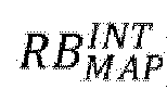
    • RB MAP RS RB MAP INT
      Figure imgb0131
      (i.e., the intersection of RB MAP RS
      Figure imgb0132
      and RB MAP INT
      Figure imgb0133
      ).
    • RB MAP RS , GB
      Figure imgb0134
      .
    • RB MAP RS , GB RB MAP INT
      Figure imgb0135
      (i.e., the intersection of RB MAP RS , GB
      Figure imgb0136
      and RB MAP INT
      Figure imgb0137
      ).
    RB MAP RS
    Figure imgb0138
    is all RBs in the union of all RB sets in the set RSMAP (or referred to as "a set consisting of all RBs in the union of all RB sets in the set RSMAP "). RB MAP INT
    Figure imgb0139
    is all RBs corresponding to all interlaces in the set IMAP (or referred to as "a set consisting of all RBs corresponding to all interlaces in the set IMAP "). RB MAP RS , GB
    Figure imgb0140
    is the union of RB MAP RS
    Figure imgb0141
    and RB MAP GB
    Figure imgb0142
    , where RB MAP GB
    Figure imgb0143
    is all RBs in the union of all guard bands (if any) between all RB sets in the set RSMAP (or referred to as "a set consisting of all RBs in the union of all guard bands (if any) between all RB sets in the set RSMAP ).
  • For example, if MINT = 5, IMAP = {int 0, int 1}, where the CRBs corresponding to int 0 are {10, 15, 20, ...}, and the CRBs corresponding to int 1 are {11, 16, 21, ...}, and RSMAP = {rs 0, rs 1}, where the CRBs corresponding to rs 0 are {10, 11, 12, ..., 59}, and the CRBs corresponding to rs 1 are {66, 67, 68, ..., 115}, then
    • RB MAP RS = 10 , 11 , 12 , , 59 66 , 67 , 68 , , 115 = 10 , 11 , 12 , , 59 , 66 , 67 , 68 , , 11 5 .
      Figure imgb0144
    • RB MAP INT = 10 , 15 , 20 , 11 , 16 , 21 , = 10 , 11 , 15 , 16 , 20 , 21 ,
      Figure imgb0145
      .
    • RB MAP GB = 60 , 61 , 62 , 63 , 64 , 65
      Figure imgb0146
      .
    • RB MAP RS , GB = 10 , 11 , 12 , , 59 , 66 , 67 , 68 , , 115 60 , 61 , 62 , 63 , 64 , 65 =
      Figure imgb0147
      {10, 11, 12, ..., 115}.
    Correspondingly, f MAP RB I MAP , RS MAP
    Figure imgb0148
    may be equal to one of the following:
    • RB MAP RS ,
      Figure imgb0149
      , i.e., {10, 11, 12, ..., 59, 66, 67, 68, ..., 115}.
    • RB MAP RS RB MAP INT
      Figure imgb0150
      , i.e., {10, 11, 15, 16, 20, 21, ..., 55, 56, 66, 70, 71, 75, 76, 80, 81, ..., 110, 111, 115}.
    • RB MAP RS , GB ,
      Figure imgb0151
      , i.e., {10, 11, 12, ..., 115}.
    • RB MAP RS , GB RB MAP INT ,
      Figure imgb0152
      , i.e., {10, 11, 15, 16, 20, 21, ..., 110, 111, 115}.
  • For different uses (e.g., resource mappings for different channels or signals), the definition of f MAP RB I MAP , RS MAP
    Figure imgb0153
    may be different.
  • For the unlicensed spectrum, after successful channel access, in order to avoid that other communication nodes also (at the same time, or at a later time) detect that the channel is available and occupy the channel (resulting in a conflict), the corresponding transmission should be started as soon as possible. In another aspect, in a communication system (e.g., a communication system using NR technology), the start time of a transmission may not be arbitrary, but is limited to some discrete time points. For example, the start time can only be located at the start time of one slot, or at the start time of a particular symbol (e.g., the first SL symbol) in one slot, which greatly limits the flexibility of performing transmission in the unlicensed spectrum. This problem can be alleviated to some extent by introducing a cyclic prefix extension (CPE) function. For example, if it is assumed that t = 0 corresponds to the start time of a subframe, and the start time of the symbol indexed as l ∈ {0, 1, ···, N slot subframe , μ N symb slot 1
    Figure imgb0154
    } in the subframe is t start , l μ
    Figure imgb0155
    , the symbol length (or referred to as the "symbol duration") is T symb , l μ
    Figure imgb0156
    , so that in the case that the CPE is used, transmission (e.g., denoted as TS l 0 ) corresponding to a starting symbol l 0 may start at t = t start , l 0 μ T ext , l 0
    Figure imgb0157
    (rather than t = t start , l 0 μ
    Figure imgb0158
    in the case that the CPE is not used). A time-continuous signal at t start , l 0 μ T ext , l 0 t < t start , l 0 μ
    Figure imgb0159
    may be defined as s ext , l 0 p μ t = s ¯ l 0 p μ t
    Figure imgb0160
    .
    Wherein
    • t start , l μ
      Figure imgb0161
      may be in unit of second.
    • T symb , l μ
      Figure imgb0162
      may be in unit of second.
    • T symb , l μ
      Figure imgb0163
      includes the length (e.g., denoted as N CP , l μ T c
      Figure imgb0164
      ) of the CP in the corresponding symbol and the length (e.g., denoted as N u μ T c
      Figure imgb0165
      ) of the core OFDM symbol.
    • s ¯ l 0 p μ t
      Figure imgb0166
      represents the time-continuous signal of the symbol l 0 at t start , l 0 μ t < t start , l 0 μ + T symb , l 0 μ .
      Figure imgb0167
    • p represents a corresponding antenna port.
    • µ is a corresponding subcarrier spacing configuration.
    • T ext,l 0 may be referred to as a CPE length (or a CPE duration).
    • T ext,l0 may be in unit of second.
  • For the transmission TS l 0 , the CPE length T ext,l 0 may be defined in one of the following manners:
    • T ext , l 0 = min max T ext 0 , l 0 , 0 , T bnd , l 0 CPE
      Figure imgb0168
      .
    • T ext , l 0 = T ext 0 , l 0
      Figure imgb0169
      .
    • T ext , l 0 = T bnd , l 0 CPE .
      Figure imgb0170
    Wherein
    • T ext,l0 may be defined differently for transmissions scheduled (or triggered) in different manners. For example, for a transmission scheduled by a dynamic grant, T ext , l 0 = min max T ext 0 , l 0 , 0 , T bnd , l 0 CPE
      Figure imgb0171
      . As another example, for a transmission scheduled by a configured grant, T ext,l0 =T ext0,l0 .
    • T bnd , l 0 CPE
      Figure imgb0172
      , may be equal to the sum of the lengths of the N bnd , l 0 CPE N bnd , l 0 CPE
      Figure imgb0173
      symbol(s) immediately preceding the symbol l 0. For example, T bnd , l 0 CPE
      Figure imgb0174
      may be defined as T bnd , l 0 CPE = k = 1 N bnd , l 0 CPE T symb , l 0 k mod 7 2 μ μ
      Figure imgb0175
      (or T bnd , l 0 CPE = k = 1 N bnd , l 0 CPE T symb , l 0 k mod 7 2 μ μ
      Figure imgb0176
      ). Specifically, for example, N bnd , l 0 CPE = 1
      Figure imgb0177
      . Accordingly, the " N bnd , l 0 CPE
      Figure imgb0178
      symbols" correspond to the symbol immediately preceding the symbol l0, and is, for example, denoted as l 0, m1. As another example, N bnd , l 0 CPE = 2
      Figure imgb0179
      . Accordingly, the " N bnd , l 0 CPE
      Figure imgb0180
      symbols" correspond to the symbol (e.g., denoted as the symbol l 0, m1) immediately preceding the symbol l 0 and the symbol (e.g., denoted as the symbol l 0, m2) immediately preceding the symbol l 0, m1. Wherein
      • N bnd , l 0 CPE
        Figure imgb0181
        may be a predefined or configured or pre-configured value. For example, N bnd , l 0 CPE = 1
        Figure imgb0182
        .
      • N bnd , l 0 CPE
        Figure imgb0183
        may be a value indicated via downlink control information (DCI) or sidelink control information (SCI). The indicated value may be an element in a predefined or configured or pre-configured set.
      • N bnd , l 0 CPE
        Figure imgb0184
        may be related to µ. For example, N bnd , l 0 CPE = 2 μ
        Figure imgb0185
        . As another example, for µ ∈ {0, 1}, N bnd , l 0 CPE = 1
        Figure imgb0186
        . As another example, for µ = 2, N bnd , l 0 CPE = 2
        Figure imgb0187
        .
    • T bnd , l 0 CPE
      Figure imgb0188
      may be equal to T symb , l bnd CPE μ bnd CPE
      Figure imgb0189
      . l bnd CPE
      Figure imgb0190
      may be equal to (l 0 - 1) mod 7 2 μ bnd CPE
      Figure imgb0191
      (or l 0 1 mod 7 2 μ bnd CPE
      Figure imgb0192
      ), or may be a predefined or configured or pre-configured symbol index in a subframe. μ bnd CPE
      Figure imgb0193
      may be equal to µ, or may be a predefined or configured or pre-configured subcarrier spacing configuration. For example, μ bnd CPE = 0 , l bnd CPE = 0
      Figure imgb0194
      . As another example, μ bnd CPE = μ
      Figure imgb0195
      , and l bnd CPE = 0
      Figure imgb0196
      .
    • T ext0,l0 may be equal to the sum of the lengths of the N ext 0 , l 0 CPE
      Figure imgb0197
      symbols preceding the symbol l 0 minus an offset value (e.g., denoted as Δ ACCTA CPE
      Figure imgb0198
      ) related to channel access and/or timing advance, or may be equal to T bnd , l 0 CPE
      Figure imgb0199
      minus Δ ACCTA CPE
      Figure imgb0200
      , or may be equal to T symb , l bnd CPE μ bnd CPE
      Figure imgb0201
      minus Δ ACCTA CPE
      Figure imgb0202
      . For example, T ext 0 , l 0
      Figure imgb0203
      may be defined as T ext 0 , l 0 = k = 1 N ext 0 , l 0 CPE T symb , l 0 k mod 7 2 μ μ Δ ACCTA CPE
      Figure imgb0204
      (or, T ext 0 , l 0 = k = 1 N ext 0 , l 0 CPE T symb , l 0 k mod 7 2 μ μ Δ ACCTA CPE
      Figure imgb0205
      ), or may be defined as T ext 0 , l 0 = T bnd , l 0 CPE Δ ACCTA CPE
      Figure imgb0206
      , or may be defined as T ext 0 , l 0 = T symb , l bnd CPE μ bnd CPE Δ ACCTA CPE
      Figure imgb0207
      . Wherein
      • N ext 0 , l 0 CPE
        Figure imgb0208
        may be a predefined or configured or pre-configured value. For example, N ext 0 , l 0 CPE = 1
        Figure imgb0209
        .
      • N ext 0 , l 0 CPE
        Figure imgb0210
        may be a value indicated via DCI or SCI. The indicated value may be an element in a predefined or configured or pre-configured set.
      • N ext 0 , l 0 CPE
        Figure imgb0211
        may be related to µ. For example, N ext 0 , l 0 CPE = 2 μ
        Figure imgb0212
        . As another example, for µ ∈ {0, 1}, N ext 0 , l 0 CPE = 1
        Figure imgb0213
        . As another example, for µ = 2, N ext 0 , l 0 CPE = 2
        Figure imgb0214
        .
      • N ext 0 , l 0 CPE
        Figure imgb0215
        may be the greatest integer satisfying T ext 0 , l 0 < T symb , l 0 1 mod 7 2 μ μ
        Figure imgb0216
        (or, T ext 0 , l 0 < T symb , l 0 1 mod 7 2 μ μ
        Figure imgb0217
        ).
      • N ext 0 , l 0 CPE
        Figure imgb0218
        may be the greatest integer satisfying T ext 0 , l 0 T symb , l 0 1 mod 7 2 μ μ
        Figure imgb0219
        (or, T ext 0 , l 0 T symb , l 0 1 mod 7 2 μ μ
        Figure imgb0220
        ).
      • N ext 0 , l 0 CPE
        Figure imgb0221
        may be the greatest integer satisfying T ext 0 , l 0 < T bnd , l 0 CPE
        Figure imgb0222
        .
      • N ext 0 , l 0 CPE
        Figure imgb0223
        may be the greatest integer satisfying T ext 0 , l 0 T bnd , l 0 CPE
        Figure imgb0224
        .
      • Δ ACCTA CPE
        Figure imgb0225
        may be in unit of second.
      • Δ ACCTA CPE
        Figure imgb0226
        may be related to N ext 0 , l 0 CPE
        Figure imgb0227
        . For example, each value of N ext 0 , l 0 CPE
        Figure imgb0228
        corresponds to a unique value of Δ ACCTA CPE
        Figure imgb0229
        .
      • Δ ACCTA CPE
        Figure imgb0230
        may be a predefined or configured or pre-configured value. For example, Δ ACCTA CPE = 16 10 6
        Figure imgb0231
        . As another example, Δ ACCTA CPE = 25 10 6
        Figure imgb0232
        . As another example, Δ ACCTA CPE = 34 10 6
        Figure imgb0233
        . As another example, Δ ACCTA CPE = 43 10 6
        Figure imgb0234
        . As another example, Δ ACCTA CPE = 52 10 6
        Figure imgb0235
        . As another example, Δ ACCTA CPE = 61 10 6
        Figure imgb0236
        .
      • Δ ACCTA CPE
        Figure imgb0237
        may be a value indicated via DCI or SCI. The indicated value may be an element in a predefined or configured or pre-configured set.
      • ■ A pair formed by a given value of N ext 0 , l 0 CPE
        Figure imgb0238
        (e.g., N ext 0 , l 0 CPE = 1
        Figure imgb0239
        ) and a given value of Δ ACCTA CPE
        Figure imgb0240
        (e.g., Δ ACCTA CPE = 25 10 6
        Figure imgb0241
        ) may be indicated via a configured value or a value indicated in DCI or a value indicated in SCI, and the pair may be an element in a predefined or configured or pre-configured set.
      • Δ ACCTA CPE
        Figure imgb0242
        may be related to µ.
      • Δ ACCTA CPE
        Figure imgb0243
        may be configured or indicated to be equal to k = 1 N ext 0 , l 0 CPE T symb , l 0 k mod 7 2 μ μ or , k = 1 N ext 0 , l 0 CPE T symb , l 0 k mod 7 2 μ μ
        Figure imgb0244
        , and correspondingly, T ext0,l o = 0.
    • ● Part or all of T ext0,lo may be defined differently for transmissions scheduled (or triggered) in different manners. For example, for a transmission scheduled by a dynamic grant, N ext 0 , l 0 CPE
      Figure imgb0245
      is a predefined value independent of µ, or is a configured or pre-configured value. As another example, for a transmission scheduled by a configured grant, N ext 0 , l 0 CPE = 2 μ
      Figure imgb0246
      .
  • A set of all possible values of T ext,l o of the transmission TS l o , (or referred to as "all allowed values of T ext,l o of the transmission TS l o ") may be denoted as E ext , l 0 CPE
    Figure imgb0247
    . The largest element in the set E ext , l 0 CPE
    Figure imgb0248
    may be denoted as T ext,max,l o .
  • For the transmission TS l o , T ext,l o may correspond to an upper boundary (e.g., referred to as the "CPE upper boundary" of the transmission TS l o , and denoted as, for example, Text,bnd,l o ). For example, T ext,bnd,l o may be equal to T ext,max,l o . As another example, T ext,bnd,l o may be a value greater than any element in the set E ext , l 0 CPE
    Figure imgb0249
    .
  • T ext,bnd,l o may be related to l 0, or may be independent of l 0.
  • T ext,bnd,l o may be related to µ, or may be independent of µ.
  • T ext,bnd,l o may be equal to one of the following:
    • T ext,max,l o .
    • ● The greatest value in T ext,max,0, T ext,max,1, ······, T ext , max , N slot subframe , μ N symb slot 1
      Figure imgb0250
      .
    • ● The greatest value in T ext,max,0, T ext,max,1, ......, T ext,max,7·2µ-1. CPE
    • T bnd , l 0 CPE
      Figure imgb0251
      .
    • ● The greatest value in T bnd , 0 CPE , T bnd , 1 CPE , , T bnd , N slot subframe , μ N symb slot 1 CPE
      Figure imgb0252
      .
    • ● The greatest value in T bnd , 0 CPE , T bnd , 1 CPE , , T bnd , 7 2 μ 1 CPE
      Figure imgb0253
      .
    • T symb , l 0 1 mod 7 2 μ μ or , T symb , l 0 1 mod 7 2 μ μ
      Figure imgb0254
      .
    • ● The greatest value in T symb , 0 μ , T symb , 1 μ , , T symb , N slot subframe , μ N symb slot 1 μ
      Figure imgb0255
      .
    • ● The greatest value in T symb , 0 μ , T symb , 1 μ , , T symb , 7 2 μ 1 μ
      Figure imgb0256
      .
    • T symb , l bnd CPE μ bnd CPE
      Figure imgb0257
      .
    • k = 1 2 μ T symb , l 0 k mod 7 2 μ μ or , k = 1 2 μ T symb , l 0 k mod 7 2 μ μ
      Figure imgb0258
      .
    • k = 1 N ext 0 , l 0 CPE T symb , l 0 k mod 7 2 μ μ or , k = 1 N ext 0 , l 0 CPE T symb , l 0 k mod 7 2 μ μ
      Figure imgb0259
      .
  • T ext,bnd,l o may be defined differently for transmissions scheduled (or triggered) in different manners. For example, for a transmission scheduled by a dynamic grant, T ext , bnd , l 0 = T symb , l 0 1 mod 7 2 μ μ or , T ext , bnd , l 0 = T symb , l 0 1 mod 7 2 μ μ
    Figure imgb0260
    . As another example, for a transmission scheduled by a configured grant, T ext , bnd , l 0 = k = 1 2 μ T symb , l 0 k mod 7 2 μ μ
    Figure imgb0261
    (or, T ext , bnd , l 0 = k = 1 2 μ T symb , l 0 k mod 7 2 μ μ
    Figure imgb0262
    ).
  • [Embodiment 1]
  • A method performed by a user equipment according to Embodiment 1 of the present invention will be described below with reference to FIG. 1.
  • FIG. 1 shows a flowchart corresponding to the method performed by user equipment according to Embodiment 1 of the present invention.
  • As shown in FIG. 1, in Embodiment 1 of the present invention, the steps performed by user equipment (UE) include: step S101 and step S103.
  • Specifically, in step S101, information related to S-SS/PSBCH block transmission (or reception) is acquired and/or determined. The "S-SS/PSBCH block" may also be referred to as "SL SSB" or "S-SSB".
  • The "information related to S-SS/PSBCH block transmission (or reception)" may be configured in an SL BWP. The SL BWP may include N RBset BWP
    Figure imgb0263
    RB sets respectively denoted as, for example, rs 0 BWP , rs 1 BWP , , rs N RBset BWP 1 BWP
    Figure imgb0264
    , in ascending order of frequencies, where N RBset BWP
    Figure imgb0265
    may be an integer greater than or equal to 1. A set consisting of the N RBset BWP
    Figure imgb0266
    RB sets may be denoted as RS BWP = rs 0 BWP , rs 1 BWP , , rs N RBset BWP 1 BWP
    Figure imgb0267
    .
  • For i 0 , 1 , , N RBset BWP 1
    Figure imgb0268
    , the lowest indexed common resource block (CRB) and the highest indexed CRB of rs i BWP
    Figure imgb0269
    may be respectively denoted as N i BWP , RS , start
    Figure imgb0270
    and N i BWP , RS , end
    Figure imgb0271
    . The number of RBs of rsi BWP may be denoted as N i BWP , RS , size
    Figure imgb0272
    . N i BWP , RS , size
    Figure imgb0273
    may be equal to N i BWP , RS , end N i BWP , RS , start + 1
    Figure imgb0274
    . In addition, N GB BWP = N RBset BWP 1
    Figure imgb0275
    guard bands (or referred to as "intra-cell guard bands") for separating the N RBset BWP
    Figure imgb0276
    RB sets may be present in the SL BWP, and are respectively denoted as, for example, gb 0 BWP , gb 1 BWP ,
    Figure imgb0277
    , gb N GB BWP 1 BWP
    Figure imgb0278
    . For j 0 , 1 , , N GB BWP 1
    Figure imgb0279
    , gb j BWP
    Figure imgb0280
    may be used to separate the RB set rs j BWP
    Figure imgb0281
    and the RB set rs j + 1 BWP
    Figure imgb0282
    . The lowest indexed CRB and the highest indexed CRB of gb j BWP
    Figure imgb0283
    may be respectively denoted as N j BWP , GB , start
    Figure imgb0284
    and N j BWP , GB , end
    Figure imgb0285
    . The number of RBs may be denoted as N j BWP , GB , size
    Figure imgb0286
    . N j BWP , GB , size
    Figure imgb0287
    may be equal to N j BWP , GB , end
    Figure imgb0288
    N j BWP , GB , start + 1
    Figure imgb0289
    . The lowest indexed CRB of the SL BWP may be equal to N 0 BWP , RS , start
    Figure imgb0290
    . The number of RBs of the SL BWP may be defined as N size BWP = N N RBset BWP 1 BWP , RS , end N 0 BWP , RS , start + 1
    Figure imgb0291
    .
  • For example, 216 consecutive RBs are configured in the SL BWP (e.g., corresponding CRB indexes are respectively 0, 1, ..., 215), and the 216 RBs may be respectively located in the following three sets:
    • ● RB set rs 0 BWP
      Figure imgb0292
      , with N 0 BWP , RS , start = 0 , N 0 BWP , RS , end = 104
      Figure imgb0293
      , and N 0 BWP , RS , size = 105
      Figure imgb0294
      .
    • ● guard band gb 0 BWP
      Figure imgb0295
      , with N 0 BWP , GB , start = 105 , N 0 BWP , GB , end = 110 , and N 0 BWP , GB , size = 6
      Figure imgb0296
      .
    • ● RB set rs 1 BWP
      Figure imgb0297
      , with N 1 BWP , RS , start = 111 , N 1 BWP , RS , end = 215 , and N 1 BWP , RS , size = 105
      Figure imgb0298
      .
  • In the frequency domain, transmission (or reception) of one S-SS/PSBCH block may correspond to N SC , ALL SSSB
    Figure imgb0299
    subcarriers. N SC , ALL SSSB
    Figure imgb0300
    may be a predefined or configured or pre-configured value, or may be determined by one or more predefined or configured or pre-configured values, or may be determined in another manner. For example, N SC , ALL SSSB = 132
    Figure imgb0301
    . As another example, N SC , ALL SSSB
    Figure imgb0302
    is an integer multiple of 132. As another example, N SC , ALL SSSB = 240
    Figure imgb0303
    . As another example, N SC , ALL SSSB
    Figure imgb0304
    is an integer multiple of 240. The N SC , ALL SSSB
    Figure imgb0305
    subcarriers may be respectively indexed as 0, 1, ······, N SC , ALL SSSB 1
    Figure imgb0306
    in a certain order (e.g., in ascending order of center frequencies of the subcarriers).
  • The N SC , ALL SSSB
    Figure imgb0307
    subcarriers may be N SC , ALL SSSB
    Figure imgb0308
    consecutive subcarriers. For example, the N SC , ALL SSSB
    Figure imgb0309
    subcarriers may correspond to N SC , ALL SSSB
    Figure imgb0310
    consecutive subcarriers, starting from the first subcarrier of a certain PRB, in the SL BWP.
  • The N SC , ALL SSSB
    Figure imgb0311
    subcarriers may be subcarriers in N RB , ALL SSSB = N SC , ALL SSSB / 12
    Figure imgb0312
    RBs, where N SC , ALL SSSB
    Figure imgb0313
    may be an integer multiple of 12.
  • The N RB , ALL SSSB
    Figure imgb0314
    RBs may be in the same RB set (e.g., denoted as rs x BWP
    Figure imgb0315
    , wherein x ∈ {0, 1 , , N RBset BWP 1
    Figure imgb0316
    }). For example, indexes of the N RB , ALL SSSB
    Figure imgb0317
    RBs in the RB set rs x BWP
    Figure imgb0318
    may be respectively X 0 N RB , ALL SSSB / 2 Δ RB SSSB , X 0 N RB , ALL SSSB 2 1 . Δ RB SSSB , , X 0 1 Δ RB SSSB
    Figure imgb0319
    , X 0 , X 0 + 1 Δ RB SSSB , , X 0 + N RB , ALL SSSB 2 1 . Δ RB SSSB , and X 0 + N RB , ALL SSSB / 2 Δ RB SSSB
    Figure imgb0320
    . X 0 may be equal to N x BWP , RS , size / 2
    Figure imgb0321
    . Δ RB SSSB
    Figure imgb0322
    may be a predefined or configured or pre-configured value, or Δ RB SSSB
    Figure imgb0323
    may be related to N x BWP , RS , size
    Figure imgb0324
    and/or N RB , ALL SSSB
    Figure imgb0325
    (or N SC , ALL SSSB
    Figure imgb0326
    ). For example, N RB , ALL SSSB = 11 , N x BWP , RS , size = 106 , X 0 = 53 , and Δ RB SSSB = 10
    Figure imgb0327
    . Accordingly, the indexes of the N RB , ALL SSSB
    Figure imgb0328
    RBs in the RB set rs x BWP
    Figure imgb0329
    may be respectively 53 - 5 · 10 = 3, 53 - 4 · 10 = 13, 53 - 3 · 10 = 23, 53 - 2 · 10 = 33, 53 - 1 · 10 = 43, 53, 53 + 1 · 10 = 63, 53 + 2 · 10 = 73, 53 + 3 · 10 = 83, 53 + 4 · 10 = 93, and 53 + 5 · 10 = 103.
  • The N SC , ALL SSSB
    Figure imgb0330
    subcarriers may be non-consecutive (or partially consecutive) subcarriers. For example, the N SC , ALL SSSB
    Figure imgb0331
    subcarriers may be subcarriers in a plurality of RBs in one or more interlaces.
  • The N SC , ALL SSSB
    Figure imgb0332
    subcarriers may be divided into N SC , GRP SSSB
    Figure imgb0333
    subcarrier groups. The N SC , GRP SSSB
    Figure imgb0334
    subcarrier groups may be respectively indexed as 0, 1, ······, N SC , GRP SSSB 1
    Figure imgb0335
    in a certain order (e.g., in ascending order of indexes of interlaces in which the subcarriers in each subcarrier group are located, or in ascending order of the center frequencies of the subcarriers having the lowest center frequencies in respective subcarrier groups). N SC , GRP SSSB
    Figure imgb0336
    may be a predefined or configured or pre-configured value, for example N SC , GRP SSSB = 1
    Figure imgb0337
    or N SC , GRP SSSB = 2
    Figure imgb0338
    . N SC , GRP SSSB = 1
    Figure imgb0339
    may correspond to a situation in which the N SC , ALL SSSB
    Figure imgb0340
    subcarriers are not grouped.
  • For g 0 , 1 , , N SC , GRP SSSB 1
    Figure imgb0341
    , the number of subcarriers included in a subcarrier group g may be denoted as N SC , g SSSB
    Figure imgb0342
    . The N SC , g SSSB
    Figure imgb0343
    subcarriers may be respectively indexed in a certain order (e.g., in ascending order of center frequencies of the subcarriers) as 0, 1, ..., N SC , g SSSB 1
    Figure imgb0344
    . N SC , g SSSB
    Figure imgb0345
    may be a value independent of g, for example N SC , g SSSB = N SCPG SSSB
    Figure imgb0346
    , wherein N SCPG SSSB
    Figure imgb0347
    is a predefined or configured or pre-configured value, for example, N SCPG SSSB = 132
    Figure imgb0348
    or N SCPG SSSB = 240
    Figure imgb0349
    . Accordingly, the relationship between N SC , ALL SSSB
    Figure imgb0350
    , N SC , GRP SSSB
    Figure imgb0351
    and N SCPG SSSB
    Figure imgb0352
    may be N SC , ALL SSSB = N SCPG SSSB N SC , GRP SSSB
    Figure imgb0353
    .
  • Each of the N SC , GRP SSSB
    Figure imgb0354
    subcarrier groups may consist of subcarriers in a plurality of RBs in the same interlace. Each subcarrier group may correspond to a unique predefined or configured or pre-configured interlace. For example, if g 1 0 , 1 , , N SC , GRP SSSB 1
    Figure imgb0355
    , g 2 0 , 1 , , N SC , GRP SSSB 1
    Figure imgb0356
    and g 1g 2, the subcarrier group g 1 may consist of subcarriers in a plurality of RBs in an interlace, and the subcarrier group g 2 may consist of subcarriers in a plurality of RBs in another interlace. The plurality of RBs in each subcarrier group may be determined in a predefined or configured or pre-configured manner (e.g., a plurality of RBs with consecutive IRB numbers in an interlace may be determined according to a predefined or configured or pre-configured starting IRB in the corresponding interlace and a predefined or configured or pre-configured number of IRBs).
  • CRB (or PRB) ranges corresponding to the subcarriers in any two of the N SC , GRP SSSB
    Figure imgb0357
    subcarrier groups may not overlap with each other. For example, µ = 0, MINT = 10, N SC , ALL SSSB =
    Figure imgb0358
    132, and N SC , GRP SSSB = 2
    Figure imgb0359
    . The subcarrier group 0 includes 72 subcarriers i . e . , N SC , 0 SSSB = 72
    Figure imgb0360
    . For example, the 72 subcarriers may consist of subcarriers in six CRBs with respective numbers of 0, 10, 20, 30, 40, and 50 in the interlace 0, and the corresponding CRB range may be denoted as [0, 50]. The subcarrier group 1 includes 60 subcarriers (i.e., N SC , 1 SSSB = 60
    Figure imgb0361
    ). For example, the 60 subcarriers may consist of subcarriers in five CRBs with respective numbers of 55, 65, 75, 85, and 95 in the interlace 5, and the corresponding CRB range may be denoted as [55, 95].
  • For g 0 , 1 , , N SC , GRP SSSB 1 , N SC , g SSSB
    Figure imgb0362
    subcarriers in the subcarrier group g may be consecutive subcarriers. For example, the N SC , g SSSB
    Figure imgb0363
    subcarriers may correspond to N SC , g SSSB
    Figure imgb0364
    consecutive subcarriers, starting from the first subcarrier of a certain PRB, in the SL BWP.
  • For g 0 , 1 , , N SC , GRP SSSB 1 , N SC , g SSSB
    Figure imgb0365
    subcarriers in the subcarrier group g may be non-consecutive (or partially consecutive) subcarriers.
  • When the N SC , ALL SSSB
    Figure imgb0366
    subcarriers are to be indexed, all of the subcarriers in the first subcarrier group (i.e., the subcarrier group 0) may be indexed first, then all of the subcarriers in the second subcarrier group (i.e., the subcarrier group 1) may be indexed, ..., and finally all of the subcarriers in the N SC , GRP th SSSB
    Figure imgb0367
    subcarrier group (i.e., the subcarrier group N SC , GRP SSSB 1
    Figure imgb0368
    ) may be indexed. For each subcarrier group, indexing may be performed in ascending order of indexes of corresponding subcarriers in the subcarrier group. For example, N SCPG SSSB = 132 , N SC , GRP SSSB = 2
    Figure imgb0369
    . Accordingly, N SC , ALL SSSB = N SCPG SSSB N SC , GRP SSSB = 264
    Figure imgb0370
    . For the 264 subcarriers, the subcarriers in the subcarrier group 0 are respectively indexed as 0, 1, ..., 131 in ascending order of the indexes thereof in the subcarrier group 0, and then the subcarriers in the subcarrier group 1 are respectively indexed as 132, 133, ..., 263 in ascending order of the indexes thereof in the subcarrier group 1.
  • A "basic subcarrier group" (e.g., the subcarrier group 0) may be predefined or configured or pre-configured in the N SC , GRP SSSB
    Figure imgb0371
    subcarrier groups. For each symbol of an S-SS/PSBCH block to be transmitted, resource elements (REs) corresponding to the subcarriers in the basic subcarrier group may be respectively copied to REs corresponding to the subcarriers in each other subcarrier group (for example, for each other subcarrier group g, the REs respectively corresponding to the subcarriers 0, 1, ..., N SCPG SSSB 1
    Figure imgb0372
    in the basic subcarrier group are respectively copied to the REs respectively corresponding to the subcarriers 0, 1, ..., N SCPG SSSB 1
    Figure imgb0373
    in the subcarrier group g). Specifically, for example, N SC , GRP SSSB = 3
    Figure imgb0374
    and N SCPG SSSB = 132
    Figure imgb0375
    . Accordingly, for each symbol of an S-SS/PSBCH block, the S-SS/PSBCH block may be first mapped to REs corresponding to the subcarriers 0, 1, ..., 131 in the basic subcarrier group (e.g., the subcarrier group 0), then REs respectively corresponding to the subcarriers 0, 1, ..., 131 in the basic subcarrier group are respectively copied to REs respectively corresponding to the subcarriers 0, 1, ..., 131 in the subcarrier group 1, and then REs respectively corresponding to the subcarriers 0, 1, ..., 131 in the basic subcarrier group are respectively copied to REs corresponding to the subcarriers 0, 1, ..., 131 in the subcarrier group 2.
  • An "anchor subcarrier" may be determined in the N SC , ALL SSSB
    Figure imgb0376
    subcarriers. For example, the index of the anchor subcarrier in an S-SS/PSBCH block may be denoted as sc anc SSSB
    Figure imgb0377
    , where sc anc SSSB 0 , 1 , , N SC , ALL SSSB 1
    Figure imgb0378
    . sc anc SSSB
    Figure imgb0379
    may be a predefined or configured or pre-configured value, or may be determined by one or more predefined or configured or pre-configured values. For example, sc anc SSSB = 66
    Figure imgb0380
    , or sc anc SSSB = 120
    Figure imgb0381
    , or sc anc SSSB = 0
    Figure imgb0382
    . As another example, sc anc SSSB = N SC , ALL SSSB 1
    Figure imgb0383
    . As another example, sc anc SSSB = N SC , ALL SSSB / 2
    Figure imgb0384
    . As another example, sc anc SSSB = N SCPG SSSB / 2
    Figure imgb0385
    . As another example, sc anc SSSB = N SC , ALL SSSB / 2
    Figure imgb0386
    .
  • The anchor subcarrier may be a predefined or configured or pre-configured subcarrier (e.g., indexed as sc g 0 , s 0 SSSB
    Figure imgb0387
    in the subcarrier group g 0) in a predefined or configured or pre-configured subcarrier group (e.g., indexed as g 0) in an S-SS/PSBCH block. For example, g 0 = 0. As another example, g 0 corresponds to the basic subcarrier group. As another example, sc g 0 , s 0 SSSB = N SC , g 0 SSSB 1
    Figure imgb0388
    . As another example, sc g 0 , s 0 SSSB = 0
    Figure imgb0389
    . As another example, sc g 0 , s 0 SSSB = N SC , g 0 SSSB / 2
    Figure imgb0390
    . As another example, SC g 0 , s 0 SSSB = N SC , g 0 SSSB / 2
    Figure imgb0391
    . As another example, SC g 0 , s 0 SSSB = N SC , g 0 SSSB / 2 .
    Figure imgb0392
  • The "information related to S-SS/PSBCH block transmission (or reception)" may include N freq SSSB
    Figure imgb0393
    "S-SS/PSBCH block frequency locations" (or referred to as "candidate S-SS/PSBCH block frequency locations"). Each "S-SS/PSBCH block frequency location" may be used to determine the frequency location of one S-SS/PSBCH block to be transmitted (or received) (e.g., determining the frequency location of each subcarrier in the S-SS/PSBCH block). N freq SSSB
    Figure imgb0394
    may be a predefined or configured or pre-configured value, or may be determined according to one or more predefined or configured or pre-configured values.
  • One or more of the following limitations may be applied to N freq SSSB
    Figure imgb0395
    :
    • N freq SSSB 1 .
      Figure imgb0396
    • N freq SSSB N RBset BWP .
      Figure imgb0397
  • The unit of the "S-SS/PSBCH block frequency location" may be Hz, or kHz, or MHz, or the like, and accordingly, the N freq SSSB
    Figure imgb0398
    S-SS/PSBCH block frequency locations may be respectively denoted as f 0 SSSB , f 1 SSSB , , f N freq SSSB 1 SSSB
    Figure imgb0399
    in ascending order of frequencies.
  • For k ϵ 0 , 1 , , N freq SSSB 1 , f k SSSB
    Figure imgb0400
    may correspond to an NR absolute radio frequency channel number (NR-ARFCN), denoted as, for example, arf k SSSB
    Figure imgb0401
    . For example, arf k SSSB
    Figure imgb0402
    may be a value in the integer range [0, 3279165].
  • For k 0 , 1 , , N freq SSSB 1 , f k SSSB
    Figure imgb0403
    may correspond to an anchor subcarrier denoted as, for example, anc k SSSB
    Figure imgb0404
    in an S-SS/PSBCH block (or referred to as a "candidate S-SS/PSBCH block"). For example, f k SSSB
    Figure imgb0405
    may correspond to the center frequency of the anchor subcarrier anc k SSSB
    Figure imgb0406
    , and the unit of the center frequency may be Hz, or kHz, or MHz, or the like. For k 1 0 , 1 , , N freq SSSB 1 , k 2 ϵ 0 , 1 , , N freq SSSB 1
    Figure imgb0407
    and k1 ≠ k2, the method for determining the subcarrier index of anc k 1 SSSB
    Figure imgb0408
    in the corresponding S-SS/PSBCH block may be the same as the method for determining the subcarrier index of anc k 2 SSSB
    Figure imgb0409
    in the corresponding S-SS/PSBCH block. For example, the subcarrier indexes of anc k 1 SSSB
    Figure imgb0410
    and anc k 2 SSSB
    Figure imgb0411
    in the respective corresponding S-SS/PSBCH blocks are both equal to N SC , ALL SSSB / 2
    Figure imgb0412
    .
  • For k ϵ 0 , 1 , , N freq SSSB 1
    Figure imgb0413
    , one or more of the following limitations may be applied to f k SSSB
    Figure imgb0414
    and/or the frequency location of the corresponding S-SS/PSBCH block:
    • f k SSSB
      Figure imgb0415
      (or arf k SSSB
      Figure imgb0416
      ) is in the bandwidth of the SL BWP.
    • anc k SSSB
      Figure imgb0417
      is in the SL BWP.
    • ● The S-SS/PSBCH block corresponding to f k SSSB
      Figure imgb0418
      (or arf k SSSB
      Figure imgb0419
      , or anc k SSSB
      Figure imgb0420
      ) is in the SL BWP.
    • f k SSSB
      Figure imgb0421
      (or arf k SSSB
      Figure imgb0422
      ) is in the bandwidth of the RB set rs a k BWP
      Figure imgb0423
      in the SL BWP.
    • anc k SSSB
      Figure imgb0424
      is in the RB set rs a k BWP
      Figure imgb0425
      in the SL BWP.
    • ● The S-SS/PSBCH block corresponding to f k SSSB
      Figure imgb0426
      (or arf k SSSB
      Figure imgb0427
      , or anc k SSSB
      Figure imgb0428
      ) is in the RB set rs a k BWP
      Figure imgb0429
      in the SL BWP.
    • f k SSSB
      Figure imgb0430
      (or arf k SSSB
      Figure imgb0431
      ) is not in the bandwidth of any guard band (if any) in the SL BWP.
    • anc k SSSB
      Figure imgb0432
      is not in any guard band (if any) in the SL BWP.
    • ● The S-SS/PSBCH block corresponding to f k SSSB
      Figure imgb0433
      (or arf k SSSB
      Figure imgb0434
      , or anc k SSSB
      Figure imgb0435
      ) is not in any guard band (if any) in the SL BWP.
    Wherein
    • a k 0 , 1 , , N RBset BWP 1 .
      Figure imgb0436
    • ak may be determined in a predefined or configured or pre-configured manner.
    • ● For k 1 ϵ 0 , 1 , , N freq SSSB 1
      Figure imgb0437
      and k 2 ϵ 0 , 1 , , N freq SSSB 1
      Figure imgb0438
      , one or more of the following limitations may be applied to the relationship between ak1 , and a k 2 :
      • ■ If k 1k 2 , then a k 1 a k 2 .
      • ■ If k 2 = k 1 + 1, then a k 2 = a k 1 + 1.
      • ■ If k 2 = k 1 + 1, then a k 2 = (a k 1 + 1) mod N RBset BWP
        Figure imgb0439
        .
      • ■ An offset between the first subcarrier of the first RB of rs a k 1 BWP
        Figure imgb0440
        and anc k 1 SSSB
        Figure imgb0441
        is equal to an offset between the first subcarrier of the first RB of rs a k 2 BWP
        Figure imgb0442
        and anc k 2 SSSB
        Figure imgb0443
        .
      • ■ An offset between anc k 1 SSSB
        Figure imgb0444
        and the last subcarrier of the last RB of rs a k 1 BWP
        Figure imgb0445
        is equal to an offset between anc k 2 SSSB
        Figure imgb0446
        and the last subcarrier of the last RB of rs a k 2 BWP
        Figure imgb0447
        .
      • ■ If k 1 = 2 . z, k 2 = 2 · z + 1, and z 0 , 1 , , N freq SSSB 2 1
        Figure imgb0448
        , an offset between the last subcarrier of the S-SS/PSBCH block corresponding to f k 1 SSSB
        Figure imgb0449
        (or arf k 1 SSSB
        Figure imgb0450
        ) and the last subcarrier of the last RB of the RB set rs a k 1 BWP
        Figure imgb0451
        is equal to an offset between the first subcarrier of the first RB of the RB set rs a k 2 BWP
        Figure imgb0452
        and the first subcarrier of the S-SS/PSBCH block corresponding to f k 2 SSSB
        Figure imgb0453
        , (or arf k 2 SSSB
        Figure imgb0454
        ).
      • ■ If k 1 = 2 · z, k 2 = 2 · z + 1, and z 0 , 1 , , N freq SSSB 2 1
        Figure imgb0455
        , an offset between the first subcarrier of the S-SS/PSBCH block corresponding to f k 1 SSSB
        Figure imgb0456
        (or arf k 1 SSSB
        Figure imgb0457
        ) and the last subcarrier of the S-SS/PSBCH block corresponding to f k 2 SSSB
        Figure imgb0458
        (or arf k 2 SSSB
        Figure imgb0459
        ) is less than (or, less than or equal to) the bandwidth of any RB set in the set RSBWP.
    f 0 SSSB or arf 0 SSSB , or anc 0 SSSB , f 1 SSSB or arf 1 SSSB , or anc 1 SSSB
    Figure imgb0460
    , ..., and f N freq SSSB 1 SSSB
    Figure imgb0461
    or arf N freq SSSB 1 SSSB , or anc N freq SSSB 1 SSSB
    Figure imgb0462
    may be respectively configured or pre-configured via, for example, elements (e.g., respectively denoted as sl-SSBLocations[0], sl-SSBLocations[1], ..., sl SSBLocations N freq SSSB 1
    Figure imgb0463
    in a sequence corresponding to a higher-layer parameter (e.g., denoted as sl-SSBLocations). For k ϵ 0 , 1 , , N freq SSSB 1
    Figure imgb0464
    , the value of sl-SSBLocations[k] may be an NR-ARFCN, or a subcarrier offset (e.g., an offset from the subcarrier 0 of the CRB 0 to anc k SSSB
    Figure imgb0465
    , or an offset from the subcarrier 0 of the PRB 0 of the SL BWP to anc k SSSB
    Figure imgb0466
    , or an offset from the first subcarrier of the first RB of the RB set rs k BWP
    Figure imgb0467
    to anc k SSSB
    Figure imgb0468
    , or an offset from anc k SSSB
    Figure imgb0469
    to the last subcarrier of the last RB of the RB set rs k BWP
    Figure imgb0470
    , or the like), or an offset defined in another manner.
  • One of f 0 SSSB or arf 0 SSSB , or anc 0 SSSB , f 1 SSSB or arf 1 SSSB , or anc 1 SSSB
    Figure imgb0471
    , ..., and f N freq SSSB 1 SSSB or arf N freq SSSB 1 SSSB , or anc N freq SSSB 1 SSSB
    Figure imgb0472
    may be used to determine other N freq SSSB 1
    Figure imgb0473
    (for example, when N freq SSSB 2
    Figure imgb0474
    . For example, anc 0 SSSB
    Figure imgb0475
    may be configured or pre-configured via a higher-layer parameter (e.g., denoted as sl-SSBLocations0), and for k ϵ 1 , , N freq SSSB 1
    Figure imgb0476
    , anc k SSSB
    Figure imgb0477
    may be determined according to anc 0 SSSB
    Figure imgb0478
    . Specifically, for example, the subcarrier index of anc k SSSB
    Figure imgb0479
    in the RB set rs a k BWP
    Figure imgb0480
    may be equal to the subcarrier index of anc 0 SSSB
    Figure imgb0481
    in the RB set rs a 0 BWP
    Figure imgb0482
    .
  • One SL synchronization configuration may correspond to one or more time allocations for S-SS/PSBCH block transmission (or reception). The period of each time allocation may be denoted as TTAP frames, where TTAP may be a predefined or configured or pre-configured value, e.g., TTAP = 16. One frame number period may include NTAP = TFNP / TTAP time allocation periods, e.g., N TAP = 1024 16 = 64
    Figure imgb0483
    . The indexes of the time allocation periods in one frame number period may be denoted as nTA (nTA ∈ {0, 1, ..., NTAP - 1}). The slot indexes in one time allocation period may be respectively denoted as 0 , 1 , , N slot TAP , μ 1
    Figure imgb0484
    , in chronological order, wherein N slot TAP , μ
    Figure imgb0485
    may be equal to T TAP N slot frame , μ e . g . , 16 10 2 μ
    Figure imgb0486
    .
  • For each time allocation, N period SSSB
    Figure imgb0487
    S-SS/PSBCH block indexes may be present in one time allocation period, and are respectively denoted as, for example, 0 , 1 , , N period SSSB 1
    Figure imgb0488
    in chronological order. In a time allocation period, for the S-SS/PSBCH block (or referred to as the "candidate S-SS/PSBCH block") indexed as b period SSSB b period SSSB 0 , 1 , , N period SSSB
    Figure imgb0489
    1}), the index (e.g., denoted as n period SSSB
    Figure imgb0490
    , wherein n period SSSB 0 , 1 , , N slot TAP , μ 1
    Figure imgb0491
    of the slot thereof in the time allocation period may be equal to N offset SSSB + N interval SSSB + 1 b period SSSB
    Figure imgb0492
    , wherein N interval SSSB
    Figure imgb0493
    may be a predefined or configured or pre-configured slot interval, and N offset SSSB
    Figure imgb0494
    may be a predefined or configured or pre-configured slot offset.
  • For k ϵ 0 , 1 , , N freq SSSB 1 , f k SSSB
    Figure imgb0495
    (or arf k SSSB
    Figure imgb0496
    , or anc k SSSB
    Figure imgb0497
    , or rs a k BWP
    Figure imgb0498
    ) may be related to an S-SS/PSBCH block transmission (or reception) time (e.g., one or more of the following):
    • ● A slot for S-SS/PSBCH block transmission (or reception). The index of the slot may be represented using an index ( n s μ
      Figure imgb0499
      ) thereof in a corresponding subframe, or an index ( n s , f μ
      Figure imgb0500
      ) thereof in a corresponding frame, or an index ( n s , f , p μ
      Figure imgb0501
      ) thereof in a corresponding frame number period, or an index ( n period SSSB
      Figure imgb0502
      )thereof in a corresponding time allocation period.
    • ● A subframe where the slot for S-SS/PSBCH block transmission (or reception) is located.
    • ● A frame where the slot for S-SS/PSBCH block transmission (or reception) is located.
    • ● A time allocation period in which the slot for S-SS/PSBCH block transmission (or reception) is located. The index of the time allocation period may be represented using an index (nTA ) thereof in a corresponding frame number period.
    • ● The index ( b period SSSB
      Figure imgb0503
      ) of the transmitted (or received) S-SS/PSBCH block.
  • Specifically, for example, the index (ak ) of the RB set ( rs a k BWP
    Figure imgb0504
    ) where f k SSSB
    Figure imgb0505
    is located may be defined as one or more of the following:
    • ● For 0 k N freq SSSB 1 , a k = t + k mod N RBset BWP
      Figure imgb0506
      .
    • ● For k = 0, a k = t mod N RBset BWP N freq SSSB + 1
      Figure imgb0507
      .
    • ● For 0 < k N freq SSSB 1
      Figure imgb0508
      , ak = a k - 1 + 1.
  • t may be n s μ
    Figure imgb0509
    , or n s , f μ
    Figure imgb0510
    , or n s , f , p μ
    Figure imgb0511
    , or n period SSSB
    Figure imgb0512
    , or nTA, or b period SSSB
    Figure imgb0513
    .
  • Further, in step S103, the S-SS/PSBCH block transmission (or reception) is performed.
  • For example, S-SS/PSBCH block(s) is detected and/or received according to the "information related to S-SS/PSBCH block transmission (or reception)". Specifically, for example, S-SS/PSBCH block(s) is detected and/or received in a slot n period SSSB
    Figure imgb0514
    corresponding to an S-SS/PSBCH block index b period SSSB
    Figure imgb0515
    in a time allocation period in S-SS/PSBCH block frequency location(s) respectively corresponding to one or a plurality (e.g., denoted as N rcvd SSSB
    Figure imgb0516
    ) of f 0 SSSB
    Figure imgb0517
    (or arf 0 SSSB
    Figure imgb0518
    , or anc 0 SSSB
    Figure imgb0519
    ), f 1 SSSB
    Figure imgb0520
    (or arf 1 SSSB
    Figure imgb0521
    , or anc 1 SSSB
    Figure imgb0522
    ), ..., or f N freq SSSB 1 SSSB
    Figure imgb0523
    (or arf N freq SSSB 1 SSSB
    Figure imgb0524
    , or anc N freq SSSB 1 SSSB
    Figure imgb0525
    ). N rcvd SSSB
    Figure imgb0526
    may be a value in the integer range 1 N freq SSSB
    Figure imgb0527
    . For example, N rcvd SSSB = 1
    Figure imgb0528
    . The value of N rcvd SSSB
    Figure imgb0529
    may relate to the capabilities of the UE.
  • As another example, S-SS/PSBCH block(s) is transmitted according to the "information related to S-SS/PSBCH block transmission (or reception)". Specifically, for example, in a slot n period SSSB
    Figure imgb0530
    corresponding to an S-SS/PSBCH block index b period SSSB
    Figure imgb0531
    in a time allocation period, N txd SSSB
    Figure imgb0532
    RB sets for transmitting the S-SS/PSBCH block are determined from rs a 0 BWP , rs a 1 BWP , , rs a N freq SSSB 1 BWP
    Figure imgb0533
    and the S-SS/PSBCH block(s) is respectively transmitted in corresponding S-SS/PSBCH block frequency locations in the N txd SSSB
    Figure imgb0534
    RB sets. N txd SSSB
    Figure imgb0535
    may be a value in the integer range 1 N freq SSSB
    Figure imgb0536
    . For example, N txd SSSB = 1
    Figure imgb0537
    . The value of N txd SSSB
    Figure imgb0538
    may relate to the capabilities of the UE.
  • The N txd SSSB
    Figure imgb0539
    RB sets may be autonomously determined by the UE.
  • The N txd SSSB
    Figure imgb0540
    RB sets may be determined via random selection. For example, N txd SSSB
    Figure imgb0541
    RB sets for S-SS/PSBCH block transmission are randomly selected from rs a 0 BWP , rs a 1 BWP , ,
    Figure imgb0542
    rs a N freq SSSB 1 BWP
    Figure imgb0543
    .
  • The N txd SSSB
    Figure imgb0544
    RB sets may be determined by performing channel access. For example, first, one channel access procedure (e.g., when N freq SSSB = 1
    Figure imgb0545
    ) is performed for a "channel" corresponding to rs a 0 BWP
    Figure imgb0546
    , or "a multi-channel access procedure" (e.g., when N freq SSSB > 1
    Figure imgb0547
    ) is performed for "channels" respectively corresponding to rs a 0 BWP , rs a 1 BWP , , rs a N freq SSSB 1 BWP
    Figure imgb0548
    and N accOK SSSB
    Figure imgb0549
    channels of which channel access is successful are determined according to a result of the channel access procedure or "the multi-channel access procedure", wherein N accOK SSSB 0 , 1 , , N freq SSSB
    Figure imgb0550
    . Then, N txd SSSB
    Figure imgb0551
    RB sets for S-SS/PSBCH block transmission are determined among the N accOK SSSB
    Figure imgb0552
    RB sets. For example, N txd SSSB
    Figure imgb0553
    RB sets for S-SS/PSBCH block transmission are randomly selected from the N accOK SSSB
    Figure imgb0554
    RB sets.
  • Thus, according to description of Embodiment 1, provided in the present invention is a method. More than one frequency location for an S-SS/PSBCH block is allowed to be configured, and the S-SS/PSBCH block corresponding to each frequency location is within a bandwidth of a unique RB set within an SL BWP, so that the probability that the S-SS/PSBCH block can still be transmitted when one or more channel access failures occur within the SL BWP is greatly increased, thereby improving the stability of a synchronization procedure of an SL link.
  • [Variant Embodiment]
  • Hereinafter, FIG. 2 is used to illustrate user equipment that can perform the method performed by user equipment described in detail above in the present invention as a variant embodiment.
  • FIG. 2 is a block diagram showing user equipment (UE) according to the present invention.
  • As shown in FIG. 2, user equipment (UE) 20 includes a processor 201 and a memory 202. The processor 201 may include, for example, a microprocessor, a microcontroller, an embedded processor, and the like. The memory 202 may include, for example, a volatile memory (such as a random access memory (RAM)), a hard disk drive (HDD), a non-volatile memory (such as a flash memory), or other memories. etc. The memory 202 has program instructions stored thereon. The instructions, when run by the processor 201, can perform the above method performed by user equipment described in detail in the present invention.
  • The method and related equipment according to the present invention have been described above in combination with preferred embodiments. It should be understood by those skilled in the art that the method shown above is only exemplary, and the above embodiments can be combined with one another as long as no contradiction arises. The method of the present invention is not limited to the steps or sequences illustrated above. The network node and user equipment shown above may include more modules, for example, modules that may be developed or developed in the future and that may be used for a base station, an Access and Mobility Management Function (AMF), a User Plane Function (UPF), a Mobility Management Entity (MME), a Serving Gateway (S-GW), or a UE. Various identifiers shown above are only exemplary, and are not meant for limiting the present invention. The present invention is not limited to specific information elements serving as examples of these identifiers. A person skilled in the art could make various alterations and modifications according to the teachings of the illustrated embodiments. Those skilled in the art should understand that part or all of the mathematical expressions, mathematical equations, or mathematical inequations may be simplified or transformed or rewritten to some extent, for example, incorporating constant terms, or interchanging two addition terms, or interchanging two multiplication terms, or moving a term from the left side of an equation or inequation to the right side after changing the plus or minus sign thereof, or moving a term from the right side of an equation or inequation to the left side after changing the plus or minus sign thereof or the like. Mathematical expressions, mathematical equations, or mathematical inequations before and after the simplification or transformation or rewriting may be considered to be equivalent to each other.
  • It should be understood that the above-described embodiments of the present invention may be implemented by software, hardware, or a combination of software and hardware. For example, various components in the base station and user equipment in the above embodiments can be implemented by multiple devices, and these devices include, but are not limited to: an analog circuit device, a digital circuit device, a digital signal processing (DSP) circuit, a programmable processor, an application-specific integrated circuit (ASIC), a field-programmable gate array (FPGA), a complex programmable logic device (CPLD), and the like.
  • In the present invention, the term "base station" may refer to a mobile communication data and/or control switching center having specific transmission power and a specific coverage area, and, for example, has functions such as resource allocation and scheduling, and data reception and transmission. "User equipment" may refer to user mobile terminals, such as terminal devices that can communicate with a base station or a micro base station wirelessly, including a mobile phone, a laptop computer, and the like.
  • In addition, the embodiments of the present invention disclosed herein may be implemented on a computer program product. More specifically, the computer program product is a product provided with a computer-readable medium having computer program logic encoded thereon. When executed on a computing device, the computer program logic provides related operations to implement the above technical solutions of the present invention. When executed on at least one processor of a computing system, the computer program logic causes the processor to perform the operations (the method) described in the embodiments of the present invention. Such setting of the present invention is typically provided as software, codes and/or other data structures provided or encoded on the computer-readable medium, e.g., an optical medium (e.g., compact disc read-only memory (CD-ROM)), a flexible disk or a hard disk and the like, or other media such as firmware or micro codes on one or more read-only memory (ROM) or random access memory (RAM) or programmable read-only memory (PROM) chips, or a downloadable software image, a shared database and the like in one or more modules. Software or firmware or such configuration may be installed on a computing device such that one or more processors in the computing device perform the technical solutions described in the embodiments of the present invention.
  • In addition, each functional module or each feature of the base station device and the terminal device used in each of the above embodiments may be implemented or executed by circuits, which are usually one or more integrated circuits. Circuits designed to execute various functions described in this description may include general-purpose processors, digital signal processors (DSPs), application-specific integrated circuits (ASICs) or general-purpose integrated circuits, field-programmable gate arrays (FPGAs) or other programmable logic devices, discrete gates or transistor logic, or discrete hardware components, or any combination of the above. The general-purpose processor may be a microprocessor, or the processor may be an existing processor, a controller, a microcontroller, or a state machine. The aforementioned general-purpose processor or each circuit may be configured by a digital circuit or may be configured by a logic circuit. Furthermore, when advanced technology capable of replacing current integrated circuits emerges due to advances in semiconductor technology, the present invention can also use integrated circuits obtained using this advanced technology.
  • While the present invention has been illustrated in combination with the preferred embodiments of the present invention, it will be understood by those skilled in the art that various modifications, substitutions, and alterations may be made to the present invention without departing from the spirit and scope of the present invention. Therefore, the present invention should not be limited by the above-described embodiments, but should be defined by the appended claims and their equivalents.

Claims (2)

  1. A method performed by user equipment (UE), characterized by comprising:
    determining one or more frequency locations within one SL BWP for S-SS/PSBCH block reception, wherein each frequency location corresponds to a center frequency of one subcarrier in one S-SS/PSBCH block, and a bandwidth of the S-SS/PSBCH block is within a bandwidth of a unique RB set within the SL BWP; and
    receiving the S-SS/PSBCH block in part or all of the one or more frequency locations.
  2. User equipment, comprising:
    a processor; and
    a memory, having instructions stored therein,
    wherein the instructions, when run by the processor, perform the method according to claim 1.
EP23830409.1A 2022-07-01 2023-06-29 Method executed by means of user equipment, and user equipment Pending EP4550926A1 (en)

Applications Claiming Priority (2)

Application Number Priority Date Filing Date Title
CN202210777450.6A CN117395812A (en) 2022-07-01 2022-07-01 Methods executed by user equipment and user equipment
PCT/CN2023/103860 WO2024002241A1 (en) 2022-07-01 2023-06-29 Method executed by means of user equipment, and user equipment

Publications (1)

Publication Number Publication Date
EP4550926A1 true EP4550926A1 (en) 2025-05-07

Family

ID=89383287

Family Applications (1)

Application Number Title Priority Date Filing Date
EP23830409.1A Pending EP4550926A1 (en) 2022-07-01 2023-06-29 Method executed by means of user equipment, and user equipment

Country Status (3)

Country Link
EP (1) EP4550926A1 (en)
CN (1) CN117395812A (en)
WO (1) WO2024002241A1 (en)

Family Cites Families (2)

* Cited by examiner, † Cited by third party
Publication number Priority date Publication date Assignee Title
CN111356238B (en) * 2018-12-24 2025-03-25 夏普株式会社 Method performed by user equipment and user equipment
US11778572B2 (en) * 2020-05-22 2023-10-03 Qualcomm Incorporated Lite SL-SS (sidelink synchronization signal) transmission for on demand S-SSB (sidelink synchronization signal block)

Also Published As

Publication number Publication date
CN117395812A (en) 2024-01-12
WO2024002241A1 (en) 2024-01-04

Similar Documents

Publication Publication Date Title
CN113424634B (en) Signal sending and receiving method and device for unlicensed band communication
US10536973B2 (en) Preamble transmission method and apparatus
EP3334111B1 (en) Information processing method, apparatus and system
EP4436089B1 (en) Method for transmitting/receiving channel by using guard band in one carrier in wireless communication system, and device therefor
EP3905842A1 (en) Method executed by user equipment, and user equipment
EP3226638A1 (en) Message transmission method and apparatus
US20190182003A1 (en) Data transmission method on unlicensed spectrum, and device
US20250056449A1 (en) Methods and systems for downlink transmission and interlace uplink transmission
US20220006677A1 (en) Method performed by user equipment, and user equipment
KR20220143970A (en) Channel access method for performing transmission in unlicensed band, and device using same
KR20210069110A (en) Method for transmitting and receiving physical channels and signals based on BWP (bandwidth part) in unlicensed band and apparatus using the same
CN115804178B (en) Method and apparatus for detecting sidelink transmission bursts on unlicensed spectrum
EP4572396A1 (en) Method executed by user equipment and user equipment
EP4518492A1 (en) Method executed by user equipment, and user equipment
EP4550926A1 (en) Method executed by means of user equipment, and user equipment
WO2024002244A1 (en) Method executed by means of user equipment, and user equipment
US20250274953A1 (en) Method performed by user equipment, and user equipment
EP4383623A1 (en) Method executed by user equipment, and user equipment
EP4597900A1 (en) Method executed by user equipment, and user equipment
EP4412356A1 (en) Method performed by user equipment, and user equipment
WO2024002245A1 (en) Method executed by means of user equipment, and user equipment
CN120302454A (en) Method performed by user equipment and user equipment
CN120186794A (en) Method performed by user equipment and user equipment
CN119922730A (en) Method performed by user equipment and user equipment
CN119729832A (en) Method performed by user equipment and user equipment

Legal Events

Date Code Title Description
STAA Information on the status of an ep patent application or granted ep patent

Free format text: STATUS: THE INTERNATIONAL PUBLICATION HAS BEEN MADE

PUAI Public reference made under article 153(3) epc to a published international application that has entered the european phase

Free format text: ORIGINAL CODE: 0009012

STAA Information on the status of an ep patent application or granted ep patent

Free format text: STATUS: REQUEST FOR EXAMINATION WAS MADE

17P Request for examination filed

Effective date: 20250107

AK Designated contracting states

Kind code of ref document: A1

Designated state(s): AL AT BE BG CH CY CZ DE DK EE ES FI FR GB GR HR HU IE IS IT LI LT LU LV MC ME MK MT NL NO PL PT RO RS SE SI SK SM TR

DAV Request for validation of the european patent (deleted)
DAX Request for extension of the european patent (deleted)