EP4550840A1 - Loudspeaker - Google Patents
Loudspeaker Download PDFInfo
- Publication number
- EP4550840A1 EP4550840A1 EP23916691.1A EP23916691A EP4550840A1 EP 4550840 A1 EP4550840 A1 EP 4550840A1 EP 23916691 A EP23916691 A EP 23916691A EP 4550840 A1 EP4550840 A1 EP 4550840A1
- Authority
- EP
- European Patent Office
- Prior art keywords
- coil
- loudspeaker
- support
- magnet
- step structure
- Prior art date
- Legal status (The legal status is an assumption and is not a legal conclusion. Google has not performed a legal analysis and makes no representation as to the accuracy of the status listed.)
- Pending
Links
Images





Classifications
-
- H—ELECTRICITY
- H04—ELECTRIC COMMUNICATION TECHNIQUE
- H04R—LOUDSPEAKERS, MICROPHONES, GRAMOPHONE PICK-UPS OR LIKE ACOUSTIC ELECTROMECHANICAL TRANSDUCERS; ELECTRIC HEARING AIDS; PUBLIC ADDRESS SYSTEMS
- H04R9/00—Transducers of moving-coil, moving-strip, or moving-wire type
- H04R9/02—Details
- H04R9/025—Magnetic circuit
- H04R9/027—Air gaps using a magnetic fluid
-
- H—ELECTRICITY
- H04—ELECTRIC COMMUNICATION TECHNIQUE
- H04R—LOUDSPEAKERS, MICROPHONES, GRAMOPHONE PICK-UPS OR LIKE ACOUSTIC ELECTROMECHANICAL TRANSDUCERS; ELECTRIC HEARING AIDS; PUBLIC ADDRESS SYSTEMS
- H04R9/00—Transducers of moving-coil, moving-strip, or moving-wire type
- H04R9/02—Details
- H04R9/04—Construction, mounting, or centering of coil
- H04R9/045—Mounting
-
- H—ELECTRICITY
- H04—ELECTRIC COMMUNICATION TECHNIQUE
- H04R—LOUDSPEAKERS, MICROPHONES, GRAMOPHONE PICK-UPS OR LIKE ACOUSTIC ELECTROMECHANICAL TRANSDUCERS; ELECTRIC HEARING AIDS; PUBLIC ADDRESS SYSTEMS
- H04R9/00—Transducers of moving-coil, moving-strip, or moving-wire type
- H04R9/02—Details
- H04R9/04—Construction, mounting, or centering of coil
- H04R9/046—Construction
-
- H—ELECTRICITY
- H04—ELECTRIC COMMUNICATION TECHNIQUE
- H04R—LOUDSPEAKERS, MICROPHONES, GRAMOPHONE PICK-UPS OR LIKE ACOUSTIC ELECTROMECHANICAL TRANSDUCERS; ELECTRIC HEARING AIDS; PUBLIC ADDRESS SYSTEMS
- H04R9/00—Transducers of moving-coil, moving-strip, or moving-wire type
- H04R9/06—Loudspeakers
Definitions
- the present disclosure relates to the field of electrical devices, and in particular, to loudspeakers.
- Coil supports are always bonded to coils in existing loudspeakers.
- a bonding area between a coil support and a coil is not large enough, the coil is easily misaligned or detached from the coil support due to frequent vibrations, which results in inadequate reliability of a loudspeaker.
- a space utilization between the coil support and the coil is low, and a sensitivity needs to be improved.
- a loudspeaker including a magnetic circuit assembly and a coil assembly. At least a portion of the coil assembly may be provided in a magnetic gap formed by the magnetic circuit assembly, and the coil assembly may be electrified to drive a vibrating member to vibrate to produce sound.
- the coil assembly may include a coil support and a coil.
- the coil assembly may have an extended end extend toward the magnetic gap, and the extended end may have a first step structure.
- the coil may include an outer coil and an inner coil.
- the outer coil and the inner coil may form a second step structure in a direction close to the coil support, and the first step structure and the second step structure may be fitted to each other so that the coil may be fixedly mounted on the coil support.
- a height of the inner coil may be greater than a height of the outer coil along an extension direction of the coil support.
- a height of the inner coil may be less than a height of the outer coil along an extension direction of the coil support.
- a width of the inner coil may be the same as a width of the outer coil along a radial direction.
- a width of the outer coil may be greater than a width of the inner coil along a radial direction.
- the coil may be a metal wire with an elongation of no less than 20%.
- the coil may include a conductor, an insulating layer, and an adhesive layer, respectively, in a radial direction of the coil from inside to outside, and a sum of a thickness of the insulating layer and a thickness of the adhesive layer may be not less than 0.016 mm.
- a step parameter H 1 and a height position parameter H 2 of the coil may satisfy H 1 + 0.5 mm ⁇ H 2 ⁇ 1.8 mm.
- the step parameter H 1 may be 1/2 of a height difference between the inner coil and the outer coil along an extension direction of the coil support.
- the height position parameter H 2 may be a distance between a reference plane and a top portion of the coil support back away from an alignment direction.
- the reference plane may be a plane where 1/2 of the height difference between the inner coil and the outer coil along the extension direction of the coil support is located.
- the step parameter H 1 may be within a range of 0.1 mm-0.8 mm.
- the height position parameter H 2 may be within a range of 1.1 mm-1.6 mm.
- a distance between a lower step surface of the coil support and a top portion of the coil support back away from an alignment direction may be not less than 0.5 mm.
- the magnetic circuit assembly may include a first magnet and a magnetic guide cover disposed at least partially around the first magnet.
- a distance between a bottom portion of the coil and a bottom surface of an interior of the magnetic guide cover may be not less than 0.9 mm.
- a gap between the coil and the first magnet in a radial direction may be within a range of 0.25 mm-0.35 mm.
- a loudspeaker including a magnetic circuit assembly and a coil assembly.
- a portion of the coil assembly may be provided in a magnetic gap formed by the magnetic circuit assembly.
- the coil assembly may be electrified to drive a vibrating member to vibrate to produce sound.
- the coil assembly may include a coil support having an extended end extending toward the magnetic gap and a coil including an outer coil and an inner coil.
- the outer coil and the inner coil may form a step structure in a direction close to the coil support, and the coil may be a metal wire with an elongation of no less than 20%.
- Embodiments of the present disclosure provide a loudspeaker.
- the loudspeaker includes a magnetic circuit assembly and a coil assembly. At least a portion of the coil assembly is provided in a magnetic gap formed by the magnetic circuit assembly.
- the coil assembly is electrified to drive a vibrating member to vibrate to produce sound.
- the coil assembly includes a coil support.
- the coil support has an extended end extending toward the magnetic gap, and the extended end has a first step structure.
- the coil assembly further includes a coil.
- the coil includes an outer coil and an inner coil.
- the outer coil and the inner coil form a second step structure in a direction close to the coil support.
- the first step structure and the second step structure are fitted to each other so that the coil is fixedly mounted on the coil support.
- a macroscopic Ampere force generated by electrifying a straight wire is calculated by the following equation (3):
- the microscopic total Lorentz force thereon is calculated by the following equation (4):
- B r dV ⁇ I S o B r dV
- S 0 denotes a cross-sectional area of a single wire; and
- B r denotes a radial flux density modulus at each point of the coil.
- the count of windings and the cross-sectional area of the coil are constants for a specific shaped coil. Simulation calculations therefore only require volume partitioning of B r in a coil region, and dividing by the cross-sectional area of a single coil wire S 0 to obtain the value of the coil driving force factor BL.
- the coil driving force factor BL may reflect the sensitivity of the coil, and the larger the coil driving force factor BL is, the greater the sensitivity of the coil.
- FIG. 1 is a schematic diagram illustrating exemplary modules of a loudspeaker according to some embodiments of the present disclosure.
- the loudspeaker 100 may include a magnetic circuit assembly 110 and a coil assembly 120.
- the magnetic circuit assembly 110 may be configured to generate a magnetic field in space and to cause a portion of the coil assembly 120 to be provided in the magnetic field.
- the magnetic circuit assembly 110 may include a permanent magnet and other components that have magnetic conductivity.
- the magnetic circuit assembly 110 may include a magnet, a magnetic guide cover, and a magnetic guide plate. Specific descriptions regarding the magnetic circuit assembly 110 may be found in FIG. 2 , FIG. 3 , FIG. 4 , FIG. 5 , and related descriptions thereof.
- a magnetic gap may be formed in the magnetic circuit assembly 110.
- the coil assembly 120 may be configured to generate vibrations. At least a portion of the coil assembly 120 is provided in a magnetic gap formed by the magnetic circuit assembly 110, and the coil assembly 120 is electrified to drive a vibrating member to vibrate to produce sound. For example, the coil assembly 120 is electrified to generate an Ampere force under the action of an external magnetic field, such as the magnetic field generated by the magnetic circuit assembly 110, and the direction of the Ampere force is determined according to a left-hand rule.
- the coil assembly 120 may include a coil support 121 and a coil 122.
- the coil support 121 may be configured to support the coil 122.
- the coil support 121 has an extended end extending toward the magnetic gap, and the extended end has a first step structure.
- the coil support 121 may be in the shape of a torus, a hollow cylinder, a hollow ellipsoid, or the like.
- the space in the center of the coil support 121 may be used to accommodate at least a portion of the magnetic circuit assembly 110.
- the space in the center of the coil support 121 may accommodate the magnet, the magnetic guide plate, or the like.
- the coil 122 may generate an Ampere force in response to an electrified current and the external magnetic field and produce damping during vibration.
- the coil 122 may include an outer coil 122-1 and an inner coil 122-2. In a direction close to the coil support 121, the outer coil 122-1 and the inner coil 122-2 form a second step structure.
- the first step structure and the second step structure are fitted to each other so that the coil 122 is fixedly mounted on the coil support 121. It should be appreciated that what is described herein with respect to a fitted connection between the two step structures means that each step in one of the step structures is fitted to one step of the other step structure that are in contact with each other and two opposing step surfaces are in contact with each other.
- each step in the first step structure is fitted to one step in the second step structure and two opposing step surfaces are in contact with each other.
- the wire of the coil 122 may be an enameled wire, for example, a copper wire with an insulating layer, an aluminum wire, or the like. Descriptions regarding the coil 122 may be found in FIG. 7 and its related description.
- the coil 122 may be wrapped around the coil support 121. Descriptions regarding the coil 122 being wrapped around the coil support 121 may be found in FIG. 8 and its related description.
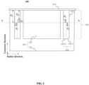
- FIG. 2 is a schematic diagram illustrating an exemplary loudspeaker according to some embodiments of the present disclosure.
- the loudspeaker 100 may include a magnetic circuit assembly 110, a coil assembly 120, and a vibration transmitting sheet 214.
- the magnetic circuit assembly 110 may include a magnetic guide cover 211 and a first magnet 212.
- the coil assembly 120 may include a coil support 121 and a coil 122.
- the coil 122 further includes an outer coil 122-1 and an inner coil 122-2.
- An extension direction shown in FIG. 2 refers to a direction in which the coil support 121 butts up against the coil 122, and a radial direction is perpendicular to the extension direction.
- the magnetic circuit assembly 110 may cause the coil 122 to be in a stable magnetic gap.
- the first magnet 212 in the magnetic circuit assembly 110 may generate a magnetic field that acts on the coil 122.
- a spatial position of the magnetic gap may include a spatial region enclosed by the magnetic guide cover 211 and the first magnet 212.
- the first magnet 212 may be a permanent magnet.
- the first magnet 212 may include a neodymium iron boron magnet, a ferrite magnet, an alnico magnet, or the like.
- the first magnet 212 may be shaped as a cylinder, an ellipsoid, or the like.
- At least a portion of the first magnet 212 may be disposed in a ring structure enclosed by the coil assembly 120.
- the exemplary gap may be 0.3 mm.
- the magnetic guide cover 211 may change a magnetic field distribution and create a magnetic shield.
- the magnetic guide cover 211 prevents the first magnet 212 from radiating a magnetic field outward.
- the magnetic guide cover 211 may be a structure having a cavity. The cavity may be configured to accommodate other components of the magnetic circuit assembly 110 and the coil assembly 120.
- the magnetic guide cover 211 may be made of a material with a high magnetic permeability, such as soft iron, silicon steel, pozzolanic alloys, ferro-aluminum alloys, or the like.
- the magnetic guide cover 211 may increase a strength of the magnetic field of the first magnet 212 at the coil assembly 120 and avoid interference of the magnetic field with other components outside.
- the vibration transmitting sheet 214 may vibrate under the drive of the coil assembly 120 and transmit the vibration to a housing of the loudspeaker 100. Further, the vibration of the housing is transmitted to auditory nerves of a user through the bones of the user's head, etc., to produce sound. In some embodiments, as shown in FIG. 2 , at least a portion of the vibration transmitting sheet 214 may be connected with the coil support 121. It should be noted that a direct connection between the vibration transmitting sheet 214 and the magnetic circuit assembly 110 (e.g., the first magnet 212 or the magnetic guide cover 211) illustrated in FIG. 2 is only exemplary, and that the vibration transmitting sheet 214 may be connected with the magnetic circuit assembly 110 (e.g., the first magnet 212 or the magnetic guide cover 211) through other connection structures, which are not limited herein.
- the coil 122 in the coil assembly 120 vibrates under an action of the electrified current and the external magnetic field and transmits the vibration to the vibration transmitting sheet 214.
- the coil support 121 may be configured to support the coil 122.
- the coil support 121 has an extended end extending toward the magnetic gap.
- the extended end has a first step structure.
- the extended end of the coil support 121 in FIG. 2 may extend in a vertically downward (e.g., downwardly extending) direction.
- the first step structure may be a step structure in the coil support 121 that contacts the coil 122. As shown in FIG.
- the first step structure includes two sections of steps, assuming that an A-A cross-section (a cross-section at 1/2 of a height difference between the inner coil 122-2 and the outer coil 122-1 along an extension direction of the coil support 121) is taken as the reference plane, the first step structure may include a raised portion and a recessed portion, the raised portion may be a step that vertically passes down through the A-A cross-section (e.g., a portion of the coil support 121 near the outer coil 122-1 shown in FIG. 2 ), and the recessed portion may be a step that does not reach the A-A cross-section (e.g., the portion of the coil support 121 near the inner coil 122-2 shown in FIG. 2 ).
- the raised portion and the recessed portion of the first step structure are connected by a transition side parallel to the extension direction.
- the raised portion of the first step structure is in contact with the outer coil 122-1 of the coil 122
- the recessed portion of the first step structure is in contact with the inner coil 122-2 of the coil 122
- the transition side between the raised portion and the recessed portion of the first step structure is in contact with the inner coil 122-2 of the coil 122.
- the coil support 121 may be in the shape of a circle, a hollow cylinder, a hollow elliptical cylinder, or the like.
- the space in the center of the coil support 121 may be configured to accommodate the magnetic circuit assembly 110.
- the space in the center of the coil support 121 may be configured to accommodate the magnet, the magnetic guide plate, or the like.
- the material of the coil support 121 may be kraft paper, asbestos paper, polyimide, aluminum foil, copper foil, fiberglass, or the like.
- the coil 122 may include an outer coil 122-1 and an inner coil 122-2.
- the inner coil 122-2 is disposed on the inner side of the coil 122 and close to the first magnet 212 in the radial direction illustrated in FIG. 2
- the outer coil 122-1 is disposed on the outer side of the coil 122 and away from the first magnet 212.
- the outer coil 122-1 and the inner coil 122-2 form a second step structure, with the first step structure fitted to the second step structure to allow the coil 122 to be fixedly mounted on the coil support 121.
- the second step structure may be a step structure in the coil 122 in contact with the coil support 121.
- a height of the inner coil 122-2 is greater than a height of the outer coil 122-1 in an extension direction of the coil support 121.
- the second step structure includes two steps, assuming that the A-A cross-section (the cross-section at 1/2 of the height difference between the inner coil 122-2 and the outer coil 122-1 along the extension direction of the coil support 121) is taken as a reference plane, the second step structure may also include a raised portion and a recessed portion, and the raised portion of the second step structure may be a step that passes vertically upwardly through the A-A cross-section (e.g., a portion of the inner coil 122-2 near the coil support 121 in FIG. 2 ).
- the raised portion of the second step structure is in contact with the recessed portion of the first step structure.
- the recessed portion of the second step structure may be a step below the A-A cross-section (e.g., the portion of the outer coil 122-1 in FIG. 2 that is near the coil support 121).
- the raised portion of the second step structure and the recessed portion of the second step structure are connected to each other by a transition side parallel to the extension direction.
- the recessed portion of the second step structure is in contact with the raised portion of the first step structure
- the raised portion of the second step structure is in contact with the recessed portion of the first step structure
- the transition side of the second step structure is in contact with the transition side of the first step structure.
- the first step structure and the second step structure may be bonded by adhesion.
- the portion of the first step structure fitted to the second step structure may be adhesively fixed by an adhesive, such as silicone.
- an adhesive such as silicone.
- the contact area between the coil support 121 and the coil 122 may be increased, the firmness of the bonding between the coil support 121 and the coil 122 may be improved, or the probability of the coil 122 being dislodged from the coil support 121 along the extension direction in the process of vibration may be reduced.
- the coil support 121 may constitute a stress constraint on the coil 122 in the radial direction, thereby avoiding misalignment of the coil 122 along the radial direction in the vibration process.
- the outer coil 122-1 and the inner coil 122-2 may be coils wound with the same wire, and there is a distinction between the inner coil and the outer coil due to the different positions of winding.
- a width of the inner coil 122-2 may be the same as a width of the outer coil 122-1 along the radial direction.
- a width of the raised portion of the second step structure in FIG. 2 is the same as a width of the recessed portion along the radial direction.
- the count of windings of the inner coil 122-2 in the radial direction is the same as that of the outer coil 122-1 in the radial direction.
- the width of the recessed portion and the width of the raised portion of the first step structure may also be the same to achieve a size match with the second step structure.
- the width of the inner coil 122-2 is the same as the width of the outer coil 122-1 in the radial direction, and the width of the recessed portion is the same as the width of the raised portion of the first step structure of the coil support 121 in the radial direction, thereby facilitating the winding of the coil 122 and the fabrication of the coil support 121.
- the coil 122 may be a metal wire with an elongation of not less than 20%.
- Exemplary metal wires may include copper alloy wires. Adopting a wire with a certain elongation (e.g., an elongation of not less than 20%) allows the coil 122 to be processed in a pre-elongating manner during a winding process, which results in good adhesion of the wires in the coil 122, a stable bonding between the coil 122 and the coil support 121, an improved firmness of the bonding of the coil support 121 with the coil 122, and a reduction of the possibility of the coil 122 falling off from the coil support 121 along the extension direction during the vibration, thereby increasing reliability.
- a copper alloy wire with the elongation of not less than 20% avoids tensile breakage or affecting the tensile strength of the coil 122 when the coil is used for pre-elongating due to insufficient ductility.
- Exemplary copper alloy wires may have an elongation of 20%, 30%, 40%, or the like.
- the copper alloy wire may include a nickel-copper alloy wire, a zirconium-copper alloy wire, or the like. It should be noted that elongation refers to the ratio of an increase in the length of the metal wire to an original length.
- the elongation of the metal wire may be measured by the IEC 60851-3 standard.
- a metal wire with a test length within a range of 200 mm-250 mm is stretched to break at a rate of (5 ⁇ 1) mm/s, a ratio of the added length after break and the original length is calculated, the test is performed 3 times to take an average, and the average is the elongation of the metal wire.
- the reference plane A-A is a plane where 1/2 of the height difference between the inner coil 122-2 and the outer coil 122-1 along the extension direction of the coil support 121 is located. It should be noted that the dimension of 4.4 mm along the extension direction of the magnetic guide cover 211 of the loudspeaker 100 used to qualify the step parameter H 1 and the height position parameter H 2 of the coil 122, and the distance 1.7 mm between the reference plane A-A and the lowest end of the bottom portion of the coil support 121 close to the magnetic guide cover 211 are only exemplary, and the person skilled in the art may adjust the parameters according to the actual needs, which are further used to determine the relationship between the step parameter H 1 and the height position parameter H 2 of the coil 122.
- a too small step parameter H 1 may result in a small contact area between the coil support 121 and the coil 122.
- the coil support 121 and the coil 122 are not fixedly connected.
- a too large step parameter H 1 may result in that the portion of the inner coil 122-2 beyond the reference plane A-A in the extension direction is too long, causing most inner coils 122-2 to be beyond the range of the strongest magnetic field, affecting the sensitivity of the coil. Therefore, to consider the fact that the coil support 121 has a large contact area with the coil 122 and that most inner coils 122-2 are located in the range of the strongest magnetic field (e.g., taking into account both the reliability and the sensitivity), the step parameter H 1 may be within a range of 0.1 mm-0.8 mm.
- the step parameter H 1 may be within a range of 0.2 mm-0.7 mm.
- the step parameter I 1 may be within a range of 0.3 mm-0.6 mm.
- the step parameter H 1 may be within a range of 0.4 mm-0.5 mm.
- the step parameter H 1 may be within a range of 0.1 mm-0.4 mm.
- the coil support 121 needs to have a certain thickness to maintain the mechanical strength of the coil support 121, and at the same time, the coil support 121 has a certain thickness may be conveniently machined, and the distance H H between the lower step surface of the coil support 121 and the coil support and the top portion of the coil support back away from the alignment direction (e.g., the height of the lower step surface of the coil support 121 along the alignment direction) is not less than 0.5 mm. As shown in FIG.
- a distance H H between a higher step surface of the second step structure along the alignment direction and the top portion of the coil support back away from the alignment direction may be characterized by a difference between the step parameter H 1 and the height position parameter H 2 .
- H H H2-H1 ⁇ 0.5 mm.
- the distance H H between the higher step surface of the second step structure along the alignment direction and the top portion of the coil support back away from the alignment direction is not less than 0.6 mm.
- the distance H H between the higher step surface of the second step structure along the alignment direction and a top portion of the coil support back away from the alignment direction is not less than 0.8 mm.
- a too large height position parameter H 2 or a too small height position parameter H 2 may result in a decrease in the value of the coil driving force factor BL, which affects the sensitivity of the loudspeaker 100, and thus in order to improve the sensitivity of the loudspeaker 100, the height position parameter H 2 may be within a range of 1.1 mm-1.6 mm.
- the height position parameter H 2 may be within a range of 1.2 mm-1.5 mm.
- the height position parameter H 2 may be within a range of 1.3 mm-1.4 mm.
- the distance between the bottom portion of the coil 122 and the bottom surface of the interior of the magnetic guide cover 211 along the extension direction of the coil support 121 may be not less than 0.9 mm.
- the distance between the bottom of the coil 122 and the bottom surface of the interior of the magnetic guide cover 211 along the extension direction of the coil support 121 may be not less than 1 mm.
- a smaller magnetic gap results in a higher coil driving force factor BL value or a higher sensitivity, but a too small magnetic gap results in the coil 122 colliding with the magnetic circuit assembly 110.
- a gap between the coil 122 and the first magnet 212 along the radial direction may be within a range of 0.25 mm-0.35 mm.
- the gap between the coil 122 and the first magnet 212 along the radial direction may be within a range of 0.28 mm-0.32 mm.
- the coil assembly 120 may include a coil support 121 and a coil 122.
- the coil 122 includes an outer coil 122-1 and an inner coil 122-2.
- the height of the inner coil 122-2 may be less than the height of the outer coil 122-1.
- the first step structure may include a raised portion and a recessed portion.
- the raised portion of the first step structure may be a step vertically down through the A-A cross-section (e.g., the portion of the coil support 121 near the inner coil 122-2 shown in FIG. 3 ), and the recessed portion of the first step structure may be a step that does not reach the A-A cross-section (e.g., the portion of the coil support 121 near the outer coil 122-1 shown in FIG. 3 ).
- the raised portion of the first step structure is connected with the recessed portion of the first step structure by a transition side parallel to the extension direction.
- the raised portion of the first step structure may be in contact with the inner coil 122-2, the recessed portion of the first step structure may be in contact with the outer coil 122-1, and the transition side between the raised portion and the recessed portion is in contact with the outer coil 122-1 of the coil 122.
- the second step structure may also include a raised portion and a recessed portion, and the raised portion of the second step structure may be a step that passes vertically upwardly through the A-A cross-section (e.g., the portion of the outer coil 122-1 that is close to the coil support 121 in FIG. 3 ). In some embodiments, the raised portion of the second step structure is in contact with the recessed portion of the first step structure.
- the recessed portion of the second step structure may be a step below the A-A cross-section (e.g., the portion of the inner coil 122-2 in FIG. 3 that is near the coil support 121).
- the raised portion of the second step structure is connected with the recessed portion of the second step structure by a transition side parallel to the extension direction.
- the recessed portion of the second step structure is in contact with the recessed portion of the first step structure
- the raised portion of the second step structure is in contact with the recessed portion of the first step structure
- the transition portion of the second step structure is in contact with the transition portion of the first step structure.
- the first step structure and the second step structure may be bonded by adhesion.
- the fitted portions of the first step structure and the second step structure may be adhesively fixed by an adhesive, such as silicone.
- an adhesive such as silicone.
- the coil 122 and the coil support 121 not only have a contact area at the raised portion and the recessed portion, respectively, but also contact each other at the transition sides of the two step structures, thus realizing the function similar to that of the step structure in FIG. 2 .
- the contact area of the coil support 121 with the coil 122 is increased, the firmness of the bonding of the coil support 121 with the coil 122 is increased, and the possibility of the coil 122 falling off from the coil support 121 along the extension direction during vibration is reduced.
- the coil support 121 may constitute a stress constraint on the coil 122 in the radial direction, thereby avoiding misalignment of the coil 122 in the radial direction in the vibration process.
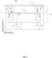
- FIG. 4 is a schematic diagram illustrating another exemplary loudspeaker according to some embodiments of the present disclosure.
- FIG. 5 is a schematic diagram illustrating another exemplary loudspeaker according to some embodiments of the present disclosure.
- the magnetic circuit assembly 110 may include a magnetic guide cover 211, a first magnet 212, a second magnet 413, and a magnetic guide plate 415.
- the magnetic guide plate 415 is disposed between the first magnet 212 and the second magnet 413, and the first magnet 212 is magnetically opposite to the second magnet 413. Providing the magnetic guide plate 415 between the first magnet 212 and the second magnet 413 of opposite magnetic properties, so that the magnetic inductance density is the highest and the magnetic field is the strongest at two sides of the magnetic guide plate 415 along the radial direction and the magnetic field.
- the coil assembly 120 may include a coil support 121 and coil 122.
- the coil 122 includes an outer coil 122-1 and an inner coil 122-2.
- the height of the inner coil 122-2 is greater than the height of the outer coil 122-1 in the extension direction of the coil support 121, referring to FIG. 2 , which is not repeated herein.
- the width of the outer coil 122-1 along the radial direction is greater than the width of the inner coil 122-2 along the radial direction.
- the width of the raised portion (e.g., the inner coil 122-2) of the second step structure in FIG. 4 along the radial direction may be less than the width of the recessed portion (e.g., the outer coil 122-1) of the second step structure along the radial direction.
- the width of the recessed portion of the first step structure may be smaller than the width of the raised portion of the first step structure to achieve a tight contact between the coil support 121 and the coil 122.
- the width of the coil 122 in the radial direction may be 0.6 mm, then the sum of the width of the outer coil 122-1 in the radial direction and the width of the inner coil 122-2 in the radial direction may be 0.6 mm.
- the width of the outer coil 122-1 in the radial direction may be 0.4 mm and the width of the inner coil 122-2 in the radial direction may be 0.2 mm.
- the width of the raised portion of the first step structure along the radial direction may be 0.4 mm, and the width of the recessed portion of the first step structure along the radial direction may be 0.2 mm.
- the step structure of the coil 122 shown in FIG. 4 may increase the contact area between the coil support 121 and the coil 122, thereby improving the firmness of the bonding between the coil support 121 and the coil 122, reducing the possibility of the coil 122 falling off from the coil 122 along the extension direction during vibration, and improving the reliability of the loudspeaker 100.
- the width of the raised portion of the second step (e.g., the outer coil 122-1) in the radial direction may be greater than the width of the recessed portion of the second step (e.g., the inner coil 122-2) in the radial direction.
- the width of the recessed portion of the first step is greater than the width of the raised portion of the first step to achieve a tight contact between the coil support 121 and the coil 122.
- the width of the coil 122 in the radial direction may be 0.6 mm, then the sum of the width of the outer coil 122-1 in the radial direction and the width of the inner coil 122-2 in the radial direction may be 0.6 mm.
- the width of the outer coil 122-1 in the radial direction may be 0.4 mm and the width of the inner coil 122-2 in the radial direction may be 0.2 mm.
- the width of the protruding portion of the first step structure in the radial direction may be 0.2 mm, and the width of the recessed portion of the first step structure in the radial direction may be 0.4 mm.
- the adaptability of the coil 122 to different shapes of the coil support 121 may be improved, and the width of the coil may be adjusted in different winding manners.
- the count of windings of the inner coil 122-2 may be no less than 3 to ensure that the loudspeaker 100 has a high reliability.
- step structure coils provided in FIG. 2-FIG. 5 of the present disclosure are for illustrative purposes only and are not intended to be a limitation of the number of steps.
- the step structure coil may also be a structure including 3 steps, 4 steps, or the like.
- Corresponding coil supports may also be structures that include 3 steps, 4 steps, etc.
- the transition side in the step structure may form any angle (not limited to 90° in FIG. 2-FIG. 5 ) with the recessed or raised portion.
- the width of the inner coil 122-2 along the radial direction may be greater than the width of the outer coil 122-1 along the radial direction, thereby achieving the same effect of increasing the contact of the coil support 121 with the coil 122 area.
- FIG. 6 is a curve illustrating a relationship between a coil driving force factor BL and a height position parameter H 2 for different step parameters H 1 according to some embodiments of the present disclosure.
- Curve 410 illustrates a relationship between the height position parameter H 2 and the coil driving force factor BL when the step parameter H 1 is 0.1 mm.
- the coil driving force factor BL increases to a peak value and then decreases gradually. From testing, the coil driving force factor BL is higher when the height position parameter H 2 is within a range of 1.1 mm-1.6 mm. Thus, coils in this range have a higher sensitivity.
- curve 410 Descriptions regarding curve 420, curve 430, curve 440, curve 450, curve 460, curve 470, and curve 480 may be referred to as the description of curve 410. It should be noted that as the step parameter H1 increases, there is less room for the coil drive factor BL to grow. As in curve 460, curve 470, and curve 480, segments of the curve in which the coil driving force factor BL increases with the increase in the height position parameter H 2 are short, that is, the coil driving force factor BL reaches the peak value rapidly and then begins to decline.
- the height of the second step structure of the coil (e.g., step parameter H 1 ) may be minimized while ensuring the reliability of the coil and the distance between the reference plane and the top portion of the coil support back away from the alignment direction (e.g., the height position parameter H 2 ) may be chosen to be within a range of 1.1 mm-1.6 mm.
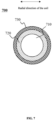
- FIG. 7 is a cross-sectional view in a radial direction of a coil according to some embodiments of the present disclosure.
- the radial direction of the coil refers to a direction from the center of the coil outward.
- the coil 122 may be made of a high-tensile wire having an adhesive layer.
- high-tensile wire described in the present disclosure refers to a wire in which the elongation of the coil 122 is greater than a certain threshold (e.g., 20%).
- the high-tensile wire may have an elongation of 20%, 30%, 40%, or the like.
- the high-tensile wire may be made from a copper alloy wire.
- Exemplary copper alloy wires may include nickel-copper alloy wires, zirconium-copper alloy wires, or the like.
- the coil 122 may be realized by the coil 700 shown in FIG. 7 .
- the coil 700 may include a conductor 710, an insulating layer 720, and an adhesive layer 730, respectively, in a radial direction of the coil from inside to outside.
- the diameter of the high-tensile wire may be within a range of 0.08 mm-0.12 mm.
- the diameter of the high-tensile wire may be 0.1 mm.
- a sum of a thickness of the insulating layer 720 and a thickness of the adhesive layer 730 (e.g., the thickness of the skin) along the radial direction of the coil 700 may be not less than 0.016 mm.
- the thickness of the insulating layer 720 may be not less than 0.008 mm along the radial direction of the coil 700, and the thickness of the adhesive layer 730 may be not less than 0.008 mm along the radial direction of the coil 700.
- the conductor 710 refers to a portion of coil 700 configured to conduct electricity.
- An exemplary conductor may include a copper wire, an aluminum wire, a copper-clad aluminum wire, a copper alloys, or the like.
- the insulating layer 720 refers to a portion coated or wrapped around the periphery of the conductor 710 for electrical insulation.
- Materials of an exemplary insulating layer may include polyethylene, polyvinyl chloride, cross-linked polyethylene, natural rubber-styrene-styrene adhesive blends, ethylene propylene rubber, butyl rubber, or the like.
- the adhesive layer 730 also referred to as a self-fusing layer, refers to an adhesion layer that is attached to the insulating layer 720 by coating, immersion, or the like.
- the adhesive layer 730 is located in an outermost layer of the coil 700.
- Materials of an exemplary adhesive layer may include polyvinyl butyral resins, modified polyamides, alcohol-based modified polyamides, hot air bonded polyamides, or the like.
- the elongation of the coil 122 is greater than a certain threshold (e.g., 20%) to make the bonding between the coil 122 and the coil support 121 stable, to improve the firmness of the bonding between the coil support 121 and the coil 122, and to reduce the possibility that the coil 122 falling off from the coil support 121 along the extension direction during vibration, thereby increasing the reliability of the loudspeaker 100.
- a certain threshold e.g. 20%
- the coils may be pre-tensioned before the coils are wound.
- a pre-tensioning may make the coil fully extended and improve a shape stability of the coil after winding.
- the pre-tensioning may make the coil extend to a certain extent based on the elongation (e.g., a copper alloy wire with an elongation of not less than 20% provided in the present disclosure), thereby avoiding that the wires may be extended again under the action of external force and destroying the stability of the winding later. Additionally, the pre-tensioning increases the pressure and friction between the layers of the coils, further improving coil shape stability.
- FIG. 8 is a schematic diagram of an arrangement of the right half of a coil of the step structure in FIG. 2 after rotating 90° counterclockwise.
- the wire of the coil 122 is wound around the magnet (e.g., the first magnet 212) starting from number 1 and lined up back and forth in three layers to number 53 (the first layer is lined up from number 1 to number 18, the second layer is lined up from number 19 to number 35, and the third layer is lined up from number 36 to number 53), and the coils of the above numbers 1 to 53 may be used as the inner coil 122-2.
- the magnet e.g., the first magnet 212
- the specific length may be 2 times the step parameter H1
- the specific length may be 2 times the step parameter H1
- the specific length may be 2 times the step parameter H1
- the width of the outer coil and the width of the inner coil along the radial direction may be controlled.
- the inner coil 122-2 of the coil 122 in FIG. 4 may be a coil including the first and second layers
- the outer coil 122-1 may be a coil including the third, fourth, fifth, and sixth layers.
- the winding may be carried out in such a way that the positioning mold 810 is first made to extend a specific length (e.g., the specific length may be 2 times the step parameter H 1 ) along the first magnet 212 to control the heights of the first, second, and third layers. Then the coil support is placed for four, five, or six layers of winding.
- the inner coil 122-2 of the coil 122 in FIG. 5 may be a coil including the first and second layers
- the outer coil 122-1 may be a coil including the third, fourth, fifth, and sixth layers.
- the number of layers of the coil and coil number in FIG. 8 are for convenience of illustration only and are not intended to be a limitation on the number of coil layers and the number of coils (or the count of windings) wound around the coil.
- the coils may be wound 5 layers, 8 layers, 18 layers, etc.
- the count of windings of the coil may be 100, 101, 150, etc.
- the embodiments of the present disclosure include, but are not limited to the following beneficial effects: (1) the contact area between the coil and the coil support is increased by setting the coil and the coil support with step structures, the stability of the coil is improved, and at the same time, the possibility of the coil falling off in the radial direction is decreased. (2) by pre-tensioning before winding, the pressure and friction between the layers of the coil are increased, to enhance the internal bonding strength of the coil and improve the space utilization. (3) by the use of high-tensile wire as the coil wire, the bonding strength between the coil and the coil support is increased, and the stacking firmness of the wires that are contact with each other in the coil is increased through the adhesive layer on the surface of the high-tensile wire. It should be noted that beneficial effects that may be produced by different embodiments are different, and the beneficial effects that may be produced in different embodiments may be any one or a combination of any of the foregoing, or any other beneficial effect that may be obtained.
Landscapes
- Physics & Mathematics (AREA)
- Engineering & Computer Science (AREA)
- Acoustics & Sound (AREA)
- Signal Processing (AREA)
- Audible-Bandwidth Dynamoelectric Transducers Other Than Pickups (AREA)
Abstract
Description
- The present disclosure relates to the field of electrical devices, and in particular, to loudspeakers.
- Coil supports are always bonded to coils in existing loudspeakers. However, a bonding area between a coil support and a coil is not large enough, the coil is easily misaligned or detached from the coil support due to frequent vibrations, which results in inadequate reliability of a loudspeaker. Additionally, a space utilization between the coil support and the coil is low, and a sensitivity needs to be improved.
- Therefore, it is desirable to provide a loudspeaker with high sensitivity and good reliability from the perspective of optimizing a configuration and materials of the coil support and the coil.
- One of the embodiments of the present disclosure provides a loudspeaker including a magnetic circuit assembly and a coil assembly. At least a portion of the coil assembly may be provided in a magnetic gap formed by the magnetic circuit assembly, and the coil assembly may be electrified to drive a vibrating member to vibrate to produce sound. The coil assembly may include a coil support and a coil. The coil assembly may have an extended end extend toward the magnetic gap, and the extended end may have a first step structure. The coil may include an outer coil and an inner coil. The outer coil and the inner coil may form a second step structure in a direction close to the coil support, and the first step structure and the second step structure may be fitted to each other so that the coil may be fixedly mounted on the coil support.
- In some embodiments, a height of the inner coil may be greater than a height of the outer coil along an extension direction of the coil support.
- In some embodiments, a height of the inner coil may be less than a height of the outer coil along an extension direction of the coil support.
- In some embodiments, a width of the inner coil may be the same as a width of the outer coil along a radial direction.
- In some embodiments, a width of the outer coil may be greater than a width of the inner coil along a radial direction.
- In some embodiments, the coil may be a metal wire with an elongation of no less than 20%.
- In some embodiments, the coil may include a conductor, an insulating layer, and an adhesive layer, respectively, in a radial direction of the coil from inside to outside, and a sum of a thickness of the insulating layer and a thickness of the adhesive layer may be not less than 0.016 mm.
- In some embodiments, a step parameter H1 and a height position parameter H2 of the coil may satisfy H 1 + 0.5 mm ≤ H 2 ≤ 1.8 mm. The step parameter H1 may be 1/2 of a height difference between the inner coil and the outer coil along an extension direction of the coil support. The height position parameter H2 may be a distance between a reference plane and a top portion of the coil support back away from an alignment direction. The reference plane may be a plane where 1/2 of the height difference between the inner coil and the outer coil along the extension direction of the coil support is located.
- In some embodiments, the step parameter H1 may be within a range of 0.1 mm-0.8 mm.
- In some embodiments, the height position parameter H2 may be within a range of 1.1 mm-1.6 mm.
- In some embodiments, a distance between a lower step surface of the coil support and a top portion of the coil support back away from an alignment direction may be not less than 0.5 mm.
- In some embodiments, the magnetic circuit assembly may include a first magnet and a magnetic guide cover disposed at least partially around the first magnet. Along the extension direction of the coil support, a distance between a bottom portion of the coil and a bottom surface of an interior of the magnetic guide cover may be not less than 0.9 mm.
- In some embodiments, a gap between the coil and the first magnet in a radial direction may be within a range of 0.25 mm-0.35 mm.
- In some embodiments, the magnetic circuit assembly may further include a second magnet and a magnetic guide plate, the magnetic guide plate may be disposed between the first magnet and the second magnet, and the first magnet and the second magnet may be of opposite magnetic properties.
- Another embodiment of the present disclosure provides a loudspeaker including a magnetic circuit assembly and a coil assembly. A portion of the coil assembly may be provided in a magnetic gap formed by the magnetic circuit assembly. The coil assembly may be electrified to drive a vibrating member to vibrate to produce sound. The coil assembly may include a coil support having an extended end extending toward the magnetic gap and a coil including an outer coil and an inner coil. The outer coil and the inner coil may form a step structure in a direction close to the coil support, and the coil may be a metal wire with an elongation of no less than 20%.
- The present disclosure is further illustrated in terms of exemplary embodiments. These exemplary embodiments are described in detail with reference to the drawings. These embodiments are non-limiting exemplary embodiments, in which like reference numerals represent similar structures, and where:
-
FIG. 1 is a schematic diagram illustrating exemplary modules of a loudspeaker according to some embodiments of the present disclosure; -
FIG. 2 is a schematic diagram illustrating an exemplary loudspeaker according to some embodiments of the present disclosure; -
FIG. 3 is a schematic diagram illustrating another exemplary loudspeaker according to some embodiments of the present disclosure; -
FIG. 4 is a schematic diagram illustrating another exemplary loudspeaker according to some embodiments of the present disclosure; -
FIG. 5 is a schematic diagram illustrating another exemplary loudspeaker according to some embodiments of the present disclosure; -
FIG. 6 is a curve illustrating a relationship between a coil driving force factor BL and a height position parameter H2 for different step parameters H1 according to some embodiments of the present disclosure; -
FIG. 7 is a cross-sectional view in a radial direction of a coil according to some embodiments of the present disclosure; and -
FIG. 8 is a schematic diagram illustrating a coil arrangement according to some embodiments of the present disclosure. - To more clearly illustrate the technical solutions related to the embodiments of the present disclosure, a brief introduction of the drawings referred to the description of the embodiments is provided below. Obviously, the drawings described below are only some examples or embodiments of the present disclosure. Those having ordinary skills in the art, without further creative efforts, may apply the present disclosure to other similar scenarios according to these drawings. Unless obviously obtained from the context or the context illustrates otherwise, the same numeral in the drawings refers to the same structure or operation.
- Embodiments of the present disclosure provide a loudspeaker. The loudspeaker includes a magnetic circuit assembly and a coil assembly. At least a portion of the coil assembly is provided in a magnetic gap formed by the magnetic circuit assembly. The coil assembly is electrified to drive a vibrating member to vibrate to produce sound. The coil assembly includes a coil support. The coil support has an extended end extending toward the magnetic gap, and the extended end has a first step structure. The coil assembly further includes a coil. The coil includes an outer coil and an inner coil. The outer coil and the inner coil form a second step structure in a direction close to the coil support. The first step structure and the second step structure are fitted to each other so that the coil is fixedly mounted on the coil support. In the present disclosure, by providing the step structures at the extended end of the coil support and the coil, a bonding area between the coil support and the coil may be increased, which further improves bonding firmness and bonding reliability. Furthermore, optionally or additionally, the coil is made of a high-tensile wire having a self-fusing layer (e.g., a copper alloy wire with an elongation of not less than 20%), which can ensure that a bonding strength inside the coil and a bonding strength between the coil and the coil support, further improving the bonding reliability.
- When the coil is electrified in a magnetic field, a Lorentz force on each electrical charge at a microscopic level is given by equation (1):


-
FIG. 1 is a schematic diagram illustrating exemplary modules of a loudspeaker according to some embodiments of the present disclosure. - As shown in
FIG. 1 , theloudspeaker 100 may include amagnetic circuit assembly 110 and acoil assembly 120. - The
magnetic circuit assembly 110 may be configured to generate a magnetic field in space and to cause a portion of thecoil assembly 120 to be provided in the magnetic field. In some embodiments, themagnetic circuit assembly 110 may include a permanent magnet and other components that have magnetic conductivity. For example, themagnetic circuit assembly 110 may include a magnet, a magnetic guide cover, and a magnetic guide plate. Specific descriptions regarding themagnetic circuit assembly 110 may be found inFIG. 2 ,FIG. 3 ,FIG. 4 ,FIG. 5 , and related descriptions thereof. In some embodiments, a magnetic gap may be formed in themagnetic circuit assembly 110. - The
coil assembly 120 may be configured to generate vibrations. At least a portion of thecoil assembly 120 is provided in a magnetic gap formed by themagnetic circuit assembly 110, and thecoil assembly 120 is electrified to drive a vibrating member to vibrate to produce sound. For example, thecoil assembly 120 is electrified to generate an Ampere force under the action of an external magnetic field, such as the magnetic field generated by themagnetic circuit assembly 110, and the direction of the Ampere force is determined according to a left-hand rule. Thecoil assembly 120 may include acoil support 121 and acoil 122. - The
coil support 121 may be configured to support thecoil 122. Thecoil support 121 has an extended end extending toward the magnetic gap, and the extended end has a first step structure. In some embodiments, thecoil support 121 may be in the shape of a torus, a hollow cylinder, a hollow ellipsoid, or the like. The space in the center of thecoil support 121 may be used to accommodate at least a portion of themagnetic circuit assembly 110. For example, the space in the center of thecoil support 121 may accommodate the magnet, the magnetic guide plate, or the like. - The
coil 122 may generate an Ampere force in response to an electrified current and the external magnetic field and produce damping during vibration. Thecoil 122 may include an outer coil 122-1 and an inner coil 122-2. In a direction close to thecoil support 121, the outer coil 122-1 and the inner coil 122-2 form a second step structure. The first step structure and the second step structure are fitted to each other so that thecoil 122 is fixedly mounted on thecoil support 121. It should be appreciated that what is described herein with respect to a fitted connection between the two step structures means that each step in one of the step structures is fitted to one step of the other step structure that are in contact with each other and two opposing step surfaces are in contact with each other. For example, each step in the first step structure is fitted to one step in the second step structure and two opposing step surfaces are in contact with each other. Specific descriptions regarding the first step structure and the second step structure may be found inFIG. 2 ,FIG. 3 ,FIG. 4 ,FIG. 5 , and their related descriptions. In some embodiments, the wire of thecoil 122 may be an enameled wire, for example, a copper wire with an insulating layer, an aluminum wire, or the like. Descriptions regarding thecoil 122 may be found inFIG. 7 and its related description. In some embodiments, thecoil 122 may be wrapped around thecoil support 121. Descriptions regarding thecoil 122 being wrapped around thecoil support 121 may be found inFIG. 8 and its related description. -
FIG. 2 is a schematic diagram illustrating an exemplary loudspeaker according to some embodiments of the present disclosure. - As shown in
FIG. 2 , theloudspeaker 100 may include amagnetic circuit assembly 110, acoil assembly 120, and avibration transmitting sheet 214. Themagnetic circuit assembly 110 may include amagnetic guide cover 211 and afirst magnet 212. Thecoil assembly 120 may include acoil support 121 and acoil 122. Thecoil 122 further includes an outer coil 122-1 and an inner coil 122-2. An extension direction shown inFIG. 2 refers to a direction in which thecoil support 121 butts up against thecoil 122, and a radial direction is perpendicular to the extension direction. - The
magnetic circuit assembly 110 may cause thecoil 122 to be in a stable magnetic gap. For example, thefirst magnet 212 in themagnetic circuit assembly 110 may generate a magnetic field that acts on thecoil 122. A spatial position of the magnetic gap may include a spatial region enclosed by themagnetic guide cover 211 and thefirst magnet 212. Thefirst magnet 212 may be a permanent magnet. For example, thefirst magnet 212 may include a neodymium iron boron magnet, a ferrite magnet, an alnico magnet, or the like. In some embodiments, thefirst magnet 212 may be shaped as a cylinder, an ellipsoid, or the like. In some embodiments, at least a portion of thefirst magnet 212 may be disposed in a ring structure enclosed by thecoil assembly 120. For example, there is a gap between thefirst magnet 212 inFIG. 2 , thecoil support 121, and thecoil 122 of thecoil assembly 120. The exemplary gap may be 0.3 mm. - The
magnetic guide cover 211 may change a magnetic field distribution and create a magnetic shield. Themagnetic guide cover 211 prevents thefirst magnet 212 from radiating a magnetic field outward. Themagnetic guide cover 211 may be a structure having a cavity. The cavity may be configured to accommodate other components of themagnetic circuit assembly 110 and thecoil assembly 120. Themagnetic guide cover 211 may be made of a material with a high magnetic permeability, such as soft iron, silicon steel, pozzolanic alloys, ferro-aluminum alloys, or the like. Themagnetic guide cover 211 may increase a strength of the magnetic field of thefirst magnet 212 at thecoil assembly 120 and avoid interference of the magnetic field with other components outside. - The
vibration transmitting sheet 214 may vibrate under the drive of thecoil assembly 120 and transmit the vibration to a housing of theloudspeaker 100. Further, the vibration of the housing is transmitted to auditory nerves of a user through the bones of the user's head, etc., to produce sound. In some embodiments, as shown inFIG. 2 , at least a portion of thevibration transmitting sheet 214 may be connected with thecoil support 121. It should be noted that a direct connection between thevibration transmitting sheet 214 and the magnetic circuit assembly 110 (e.g., thefirst magnet 212 or the magnetic guide cover 211) illustrated inFIG. 2 is only exemplary, and that thevibration transmitting sheet 214 may be connected with the magnetic circuit assembly 110 (e.g., thefirst magnet 212 or the magnetic guide cover 211) through other connection structures, which are not limited herein. - The
coil 122 in thecoil assembly 120 vibrates under an action of the electrified current and the external magnetic field and transmits the vibration to thevibration transmitting sheet 214. Thecoil support 121 may be configured to support thecoil 122. In some embodiments, thecoil support 121 has an extended end extending toward the magnetic gap. The extended end has a first step structure. The extended end of thecoil support 121 inFIG. 2 may extend in a vertically downward (e.g., downwardly extending) direction. The first step structure may be a step structure in thecoil support 121 that contacts thecoil 122. As shown inFIG. 2 , in an example that the first step structure includes two sections of steps, assuming that an A-A cross-section (a cross-section at 1/2 of a height difference between the inner coil 122-2 and the outer coil 122-1 along an extension direction of the coil support 121) is taken as the reference plane, the first step structure may include a raised portion and a recessed portion, the raised portion may be a step that vertically passes down through the A-A cross-section (e.g., a portion of thecoil support 121 near the outer coil 122-1 shown inFIG. 2 ), and the recessed portion may be a step that does not reach the A-A cross-section (e.g., the portion of thecoil support 121 near the inner coil 122-2 shown inFIG. 2 ). The raised portion and the recessed portion of the first step structure are connected by a transition side parallel to the extension direction. In some embodiments, the raised portion of the first step structure is in contact with the outer coil 122-1 of thecoil 122, the recessed portion of the first step structure is in contact with the inner coil 122-2 of thecoil 122, and the transition side between the raised portion and the recessed portion of the first step structure is in contact with the inner coil 122-2 of thecoil 122. In some embodiments, thecoil support 121 may be in the shape of a circle, a hollow cylinder, a hollow elliptical cylinder, or the like. The space in the center of thecoil support 121 may be configured to accommodate themagnetic circuit assembly 110. For example, the space in the center of thecoil support 121 may be configured to accommodate the magnet, the magnetic guide plate, or the like. In some embodiments, the material of thecoil support 121 may be kraft paper, asbestos paper, polyimide, aluminum foil, copper foil, fiberglass, or the like. - The
coil 122 may include an outer coil 122-1 and an inner coil 122-2. The inner coil 122-2 is disposed on the inner side of thecoil 122 and close to thefirst magnet 212 in the radial direction illustrated inFIG. 2 , and the outer coil 122-1 is disposed on the outer side of thecoil 122 and away from thefirst magnet 212. In a direction close to the coil support 121 (e.g., an upwardly extending direction ofFIG. 2 ), the outer coil 122-1 and the inner coil 122-2 form a second step structure, with the first step structure fitted to the second step structure to allow thecoil 122 to be fixedly mounted on thecoil support 121. The second step structure may be a step structure in thecoil 122 in contact with thecoil support 121. In some embodiments, a height of the inner coil 122-2 is greater than a height of the outer coil 122-1 in an extension direction of thecoil support 121. In an example that the second step structure includes two steps, assuming that the A-A cross-section (the cross-section at 1/2 of the height difference between the inner coil 122-2 and the outer coil 122-1 along the extension direction of the coil support 121) is taken as a reference plane, the second step structure may also include a raised portion and a recessed portion, and the raised portion of the second step structure may be a step that passes vertically upwardly through the A-A cross-section (e.g., a portion of the inner coil 122-2 near thecoil support 121 inFIG. 2 ). In some embodiments, the raised portion of the second step structure is in contact with the recessed portion of the first step structure. The recessed portion of the second step structure may be a step below the A-A cross-section (e.g., the portion of the outer coil 122-1 inFIG. 2 that is near the coil support 121). The raised portion of the second step structure and the recessed portion of the second step structure are connected to each other by a transition side parallel to the extension direction. In some embodiments, the recessed portion of the second step structure is in contact with the raised portion of the first step structure, the raised portion of the second step structure is in contact with the recessed portion of the first step structure, and the transition side of the second step structure is in contact with the transition side of the first step structure. In some embodiments, the first step structure and the second step structure may be bonded by adhesion. For example, the portion of the first step structure fitted to the second step structure may be adhesively fixed by an adhesive, such as silicone. In the present embodiment, by setting the height of the inner coil 122-2 greater than the height of the outer coil 122-1 and setting the first step structure of thecoil support 121 so that thecoil 122 and thecoil support 121 not only have a contact area at the raised portion and the recessed portion, respectively, but also contact each other at the transition sides of the two step structures. Thus, the contact area between thecoil support 121 and thecoil 122 may be increased, the firmness of the bonding between thecoil support 121 and thecoil 122 may be improved, or the probability of thecoil 122 being dislodged from thecoil support 121 along the extension direction in the process of vibration may be reduced. Furthermore, thecoil support 121 may constitute a stress constraint on thecoil 122 in the radial direction, thereby avoiding misalignment of thecoil 122 along the radial direction in the vibration process. It should be noted that the outer coil 122-1 and the inner coil 122-2 may be coils wound with the same wire, and there is a distinction between the inner coil and the outer coil due to the different positions of winding. - In some embodiments, a width of the inner coil 122-2 may be the same as a width of the outer coil 122-1 along the radial direction. For example, a width of the raised portion of the second step structure in
FIG. 2 is the same as a width of the recessed portion along the radial direction. At this time, in an example that the inner coil 122-2 and the outer coil 122-1 are wound with the same wire, the count of windings of the inner coil 122-2 in the radial direction is the same as that of the outer coil 122-1 in the radial direction. Correspondingly, the width of the recessed portion and the width of the raised portion of the first step structure may also be the same to achieve a size match with the second step structure. The width of the inner coil 122-2 is the same as the width of the outer coil 122-1 in the radial direction, and the width of the recessed portion is the same as the width of the raised portion of the first step structure of thecoil support 121 in the radial direction, thereby facilitating the winding of thecoil 122 and the fabrication of thecoil support 121. - In some embodiments, the
coil 122 may be a metal wire with an elongation of not less than 20%. Exemplary metal wires may include copper alloy wires. Adopting a wire with a certain elongation (e.g., an elongation of not less than 20%) allows thecoil 122 to be processed in a pre-elongating manner during a winding process, which results in good adhesion of the wires in thecoil 122, a stable bonding between thecoil 122 and thecoil support 121, an improved firmness of the bonding of thecoil support 121 with thecoil 122, and a reduction of the possibility of thecoil 122 falling off from thecoil support 121 along the extension direction during the vibration, thereby increasing reliability. Specific descriptions regarding the coil winding process may be found inFIG. 8 and its related descriptions. Additionally, the use of a copper alloy wire with the elongation of not less than 20% avoids tensile breakage or affecting the tensile strength of thecoil 122 when the coil is used for pre-elongating due to insufficient ductility. Exemplary copper alloy wires may have an elongation of 20%, 30%, 40%, or the like. In some embodiments, the copper alloy wire may include a nickel-copper alloy wire, a zirconium-copper alloy wire, or the like. It should be noted that elongation refers to the ratio of an increase in the length of the metal wire to an original length. In the present disclosure, the elongation of the metal wire may be measured by the IEC 60851-3 standard. For example, in the tensile instrument or tensile testing machine, a metal wire with a test length within a range of 200 mm-250 mm is stretched to break at a rate of (5±1) mm/s, a ratio of the added length after break and the original length is calculated, the test is performed 3 times to take an average, and the average is the elongation of the metal wire. - In some embodiments, in order to avoid collision caused by a too small distance between a bottom portion of the coil 122 and a bottom surface of an interior of the magnetic guide cover 211 (e.g., the distance between the bottom portion of the coil 122 and the bottom surface of the interior of the magnetic guide 211 along the extension direction of the coil support may be not less than 0.9 mm, which satisfies the requirements of HL = 4.4 mm - (H 2 + 1.7 mm) ≥ 0.9 mm. 4.4 mm denotes a dimension of the magnetic guide cover 211 of the loudspeaker 100 along the extension direction of the loudspeaker 100, and 1.7 mm denotes a distance between the reference plane A-A and a lowest end of the bottom portion of the coil support 121 near the magnetic guide cover 211), and in order to satisfy the requirements of a machining process of the coil support 121 and strength requirements (e.g., a distance between a lower step surface of the coil support 121 and a top portion of the coil support 121 back away from an alignment direction (e.g., a height of the lowest step surface of the coil support 121 along the alignment direction) is not less than 0.5 mm (HH = H 2 - H 1 ≥ 0.5 mm)), the loudspeaker 100 has a large coil driving force factor BL, and according to the above two conditions, a step parameter H1 and a height position parameter H2 of the coil 122 may satisfy H 1 + 0.5 mm ≤ H 2 ≤ 1.8 mm, where the step parameter H1 is 1/2 of the height difference between the inner coil 122-2 and the outer coil 122-1 along the extension direction of the coil support 121, and the height position parameter H2 is the distance between the reference plane A-A and the top portion of the coil support 121 back away from the alignment direction. In some embodiments, the reference plane A-A is a plane where 1/2 of the height difference between the inner coil 122-2 and the outer coil 122-1 along the extension direction of the
coil support 121 is located. It should be noted that the dimension of 4.4 mm along the extension direction of themagnetic guide cover 211 of theloudspeaker 100 used to qualify the step parameter H1 and the height position parameter H2 of thecoil 122, and the distance 1.7 mm between the reference plane A-A and the lowest end of the bottom portion of thecoil support 121 close to themagnetic guide cover 211 are only exemplary, and the person skilled in the art may adjust the parameters according to the actual needs, which are further used to determine the relationship between the step parameter H1 and the height position parameter H2 of thecoil 122. - In some embodiments, a too small step parameter H1 may result in a small contact area between the
coil support 121 and thecoil 122. Thecoil support 121 and thecoil 122 are not fixedly connected. A too large step parameter H1 may result in that the portion of the inner coil 122-2 beyond the reference plane A-A in the extension direction is too long, causing most inner coils 122-2 to be beyond the range of the strongest magnetic field, affecting the sensitivity of the coil. Therefore, to consider the fact that thecoil support 121 has a large contact area with thecoil 122 and that most inner coils 122-2 are located in the range of the strongest magnetic field (e.g., taking into account both the reliability and the sensitivity), the step parameter H1 may be within a range of 0.1 mm-0.8 mm. For example, the step parameter H1 may be within a range of 0.2 mm-0.7 mm. As another example, the step parameter I1 may be within a range of 0.3 mm-0.6 mm. Furthermore, for example, the step parameter H1 may be within a range of 0.4 mm-0.5 mm. As yet another example, the step parameter H1 may be within a range of 0.1 mm-0.4 mm. - In some embodiments, to ensure that the
coil support 121 has a certain mechanical strength and prevent thecoil support 121 from mechanical damage due to vibration of thecoil 122, thecoil support 121 needs to have a certain thickness to maintain the mechanical strength of thecoil support 121, and at the same time, thecoil support 121 has a certain thickness may be conveniently machined, and the distance HH between the lower step surface of thecoil support 121 and the coil support and the top portion of the coil support back away from the alignment direction (e.g., the height of the lower step surface of thecoil support 121 along the alignment direction) is not less than 0.5 mm. As shown inFIG. 2 , a distance HH between a higher step surface of the second step structure along the alignment direction and the top portion of the coil support back away from the alignment direction may be characterized by a difference between the step parameter H1 and the height position parameter H2. For example, HH=H2-H1≥0.5 mm. For example, the distance HH between the higher step surface of the second step structure along the alignment direction and the top portion of the coil support back away from the alignment direction is not less than 0.6 mm. For example, the distance HH between the higher step surface of the second step structure along the alignment direction and a top portion of the coil support back away from the alignment direction is not less than 0.8 mm. - In some embodiments, a too large height position parameter H2 or a too small height position parameter H2 may result in a decrease in the value of the coil driving force factor BL, which affects the sensitivity of the
loudspeaker 100, and thus in order to improve the sensitivity of theloudspeaker 100, the height position parameter H2 may be within a range of 1.1 mm-1.6 mm. For example, the height position parameter H2 may be within a range of 1.2 mm-1.5 mm. As another example, the height position parameter H2 may be within a range of 1.3 mm-1.4 mm. - In some embodiments, to avoid collision during vibration due to the too small distance between the bottom portion of the
coil 122 and the bottom surface of the interior of themagnetic guide cover 211, the distance between the bottom portion of thecoil 122 and the bottom surface of the interior of themagnetic guide cover 211 along the extension direction of thecoil support 121 may be not less than 0.9 mm. For example, the distance between the bottom of thecoil 122 and the bottom surface of the interior of themagnetic guide cover 211 along the extension direction of thecoil support 121 may be not less than 1 mm. - In some embodiments, a smaller magnetic gap results in a higher coil driving force factor BL value or a higher sensitivity, but a too small magnetic gap results in the
coil 122 colliding with themagnetic circuit assembly 110. Thus, in order to take into account the high coil driving force factor BL value or the high sensitivity and to avoid thecoil 122 from colliding with themagnetic circuit assembly 110, a gap between thecoil 122 and thefirst magnet 212 along the radial direction may be within a range of 0.25 mm-0.35 mm. For example, the gap between thecoil 122 and thefirst magnet 212 along the radial direction may be within a range of 0.28 mm-0.32 mm. -
FIG. 3 is a schematic diagram illustrating another exemplary loudspeaker according to some embodiments of the present disclosure. - As shown in
FIG. 3 , thecoil assembly 120 may include acoil support 121 and acoil 122. Thecoil 122 includes an outer coil 122-1 and an inner coil 122-2. In some embodiments, along the extension direction of thecoil support 121, the height of the inner coil 122-2 may be less than the height of the outer coil 122-1. As shown inFIG. 3 , taking the first step structure including two steps as an example and assuming that the A-A cross-section (a cross-section at 1/2 of the height difference between the inner coil 122-2 and the outer coil 122-1 along the extension direction of the coil support 121) is taken as a reference plane, the first step structure may include a raised portion and a recessed portion. The raised portion of the first step structure may be a step vertically down through the A-A cross-section (e.g., the portion of thecoil support 121 near the inner coil 122-2 shown inFIG. 3 ), and the recessed portion of the first step structure may be a step that does not reach the A-A cross-section (e.g., the portion of thecoil support 121 near the outer coil 122-1 shown inFIG. 3 ). The raised portion of the first step structure is connected with the recessed portion of the first step structure by a transition side parallel to the extension direction. In some embodiments, the raised portion of the first step structure may be in contact with the inner coil 122-2, the recessed portion of the first step structure may be in contact with the outer coil 122-1, and the transition side between the raised portion and the recessed portion is in contact with the outer coil 122-1 of thecoil 122. The second step structure may also include a raised portion and a recessed portion, and the raised portion of the second step structure may be a step that passes vertically upwardly through the A-A cross-section (e.g., the portion of the outer coil 122-1 that is close to thecoil support 121 inFIG. 3 ). In some embodiments, the raised portion of the second step structure is in contact with the recessed portion of the first step structure. The recessed portion of the second step structure may be a step below the A-A cross-section (e.g., the portion of the inner coil 122-2 inFIG. 3 that is near the coil support 121). The raised portion of the second step structure is connected with the recessed portion of the second step structure by a transition side parallel to the extension direction. In some embodiments, the recessed portion of the second step structure is in contact with the recessed portion of the first step structure, the raised portion of the second step structure is in contact with the recessed portion of the first step structure, and the transition portion of the second step structure is in contact with the transition portion of the first step structure. In some embodiments, the first step structure and the second step structure may be bonded by adhesion. For example, the fitted portions of the first step structure and the second step structure may be adhesively fixed by an adhesive, such as silicone. In the present embodiment, by setting the height of the inner coil 122-2 to be less than the height of the outer coil 122-1 and setting the first step structure of thecoil support 121, thecoil 122 and thecoil support 121 not only have a contact area at the raised portion and the recessed portion, respectively, but also contact each other at the transition sides of the two step structures, thus realizing the function similar to that of the step structure inFIG. 2 . In other words, the contact area of thecoil support 121 with thecoil 122 is increased, the firmness of the bonding of thecoil support 121 with thecoil 122 is increased, and the possibility of thecoil 122 falling off from thecoil support 121 along the extension direction during vibration is reduced. Furthermore, thecoil support 121 may constitute a stress constraint on thecoil 122 in the radial direction, thereby avoiding misalignment of thecoil 122 in the radial direction in the vibration process. -
FIG. 4 is a schematic diagram illustrating another exemplary loudspeaker according to some embodiments of the present disclosure.FIG. 5 is a schematic diagram illustrating another exemplary loudspeaker according to some embodiments of the present disclosure. - As shown in
FIG. 4 orFIG. 5 , themagnetic circuit assembly 110 may include amagnetic guide cover 211, afirst magnet 212, asecond magnet 413, and amagnetic guide plate 415. In some embodiments, themagnetic guide plate 415 is disposed between thefirst magnet 212 and thesecond magnet 413, and thefirst magnet 212 is magnetically opposite to thesecond magnet 413. Providing themagnetic guide plate 415 between thefirst magnet 212 and thesecond magnet 413 of opposite magnetic properties, so that the magnetic inductance density is the highest and the magnetic field is the strongest at two sides of themagnetic guide plate 415 along the radial direction and the magnetic field. When the region where the density of thecoil 122 is the highest is located at the two sides of themagnetic guide plate 415 along the radial direction, the coil driving force factor BL is great, which in turn makes the sensitivity of theloudspeaker 100 great. In some embodiments, thefirst magnet 212, themagnetic guide plate 415, and thesecond magnet 413 may be connected by connectors (e.g., screws). Thecoil assembly 120 may include acoil support 121 andcoil 122. Thecoil 122 includes an outer coil 122-1 and an inner coil 122-2. - In some embodiments, the height of the inner coil 122-2 is greater than the height of the outer coil 122-1 in the extension direction of the
coil support 121, referring toFIG. 2 , which is not repeated herein. In some embodiments, the width of the outer coil 122-1 along the radial direction is greater than the width of the inner coil 122-2 along the radial direction. For example, the width of the raised portion (e.g., the inner coil 122-2) of the second step structure inFIG. 4 along the radial direction may be less than the width of the recessed portion (e.g., the outer coil 122-1) of the second step structure along the radial direction. Correspondingly, the width of the recessed portion of the first step structure may be smaller than the width of the raised portion of the first step structure to achieve a tight contact between thecoil support 121 and thecoil 122. In some embodiments, the width of thecoil 122 in the radial direction may be 0.6 mm, then the sum of the width of the outer coil 122-1 in the radial direction and the width of the inner coil 122-2 in the radial direction may be 0.6 mm. For example, the width of the outer coil 122-1 in the radial direction may be 0.4 mm and the width of the inner coil 122-2 in the radial direction may be 0.2 mm. Correspondingly, the width of the raised portion of the first step structure along the radial direction may be 0.4 mm, and the width of the recessed portion of the first step structure along the radial direction may be 0.2 mm. The step structure of thecoil 122 shown inFIG. 4 may increase the contact area between thecoil support 121 and thecoil 122, thereby improving the firmness of the bonding between thecoil support 121 and thecoil 122, reducing the possibility of thecoil 122 falling off from thecoil 122 along the extension direction during vibration, and improving the reliability of theloudspeaker 100. - As shown in
FIG. 5 , the width of the raised portion of the second step (e.g., the outer coil 122-1) in the radial direction may be greater than the width of the recessed portion of the second step (e.g., the inner coil 122-2) in the radial direction. Correspondingly, the width of the recessed portion of the first step is greater than the width of the raised portion of the first step to achieve a tight contact between thecoil support 121 and thecoil 122. In some embodiments, the width of thecoil 122 in the radial direction may be 0.6 mm, then the sum of the width of the outer coil 122-1 in the radial direction and the width of the inner coil 122-2 in the radial direction may be 0.6 mm. For example, the width of the outer coil 122-1 in the radial direction may be 0.4 mm and the width of the inner coil 122-2 in the radial direction may be 0.2 mm. Correspondingly, the width of the protruding portion of the first step structure in the radial direction may be 0.2 mm, and the width of the recessed portion of the first step structure in the radial direction may be 0.4 mm. By setting the width of the outer coil 122-1 in the radial direction to be greater than the width of the inner coil 122-2 in the radial direction (as shown inFIG. 5 ), more portions of thecoil 122 may be disposed in the region of maximum magnetic field strength, resulting in a great coil driving force factor BL, and thus great sensitivity of theloudspeaker 100. - By adjusting the widths of the outer coil 122-1 and the inner coil 122-2 in the radial direction in this embodiment, the adaptability of the
coil 122 to different shapes of the coil support 121 (e.g., the coil supports with different radial widths of the step structure) may be improved, and the width of the coil may be adjusted in different winding manners. In some embodiments, the count of windings of the inner coil 122-2 may be no less than 3 to ensure that theloudspeaker 100 has a high reliability. - It should be noted that the step structure coils provided in
FIG. 2-FIG. 5 of the present disclosure are for illustrative purposes only and are not intended to be a limitation of the number of steps. For example, the step structure coil may also be a structure including 3 steps, 4 steps, or the like. Corresponding coil supports may also be structures that include 3 steps, 4 steps, etc. As another example, the transition side in the step structure may form any angle (not limited to 90° inFIG. 2-FIG. 5 ) with the recessed or raised portion. As another example, the width of the inner coil 122-2 along the radial direction may be greater than the width of the outer coil 122-1 along the radial direction, thereby achieving the same effect of increasing the contact of thecoil support 121 with thecoil 122 area. At this time, when the height of the inner coil is greater than the height of the outer coil 122-1 in the extension direction of the inner coil along thecoil support 121, a large portion of thecoil 122 is located in the region of maximum magnetic field strength, resulting in a great coil driving force factor BL, and thus great sensitivity of theloudspeaker 100. -
FIG. 6 is a curve illustrating a relationship between a coil driving force factor BL and a height position parameter H2 for different step parameters H1 according to some embodiments of the present disclosure. - As shown in
FIG.6 , when any one of the step parameter H1 and the height position parameter H2 is changed, the coil driving force factor BL is changed.Curve 410 illustrates a relationship between the height position parameter H2 and the coil driving force factor BL when the step parameter H1 is 0.1 mm. With the increase of the height position parameter H2, the coil driving force factor BL increases to a peak value and then decreases gradually. From testing, the coil driving force factor BL is higher when the height position parameter H2 is within a range of 1.1 mm-1.6 mm. Thus, coils in this range have a higher sensitivity.Descriptions regarding curve 420,curve 430,curve 440,curve 450,curve 460,curve 470, andcurve 480 may be referred to as the description ofcurve 410. It should be noted that as the step parameter H1 increases, there is less room for the coil drive factor BL to grow. As incurve 460,curve 470, andcurve 480, segments of the curve in which the coil driving force factor BL increases with the increase in the height position parameter H2 are short, that is, the coil driving force factor BL reaches the peak value rapidly and then begins to decline. - As shown in
FIG. 6 , when the height position parameter H2 is certain, the greater the step parameter H1 is, the smaller the peak value of the coil driving force factor BL is. The peak value of the coil driving force factors BL ofcurve 410,curve 420,curve 430,curve 440,curve 450,curve 460,curve 470, andcurve 480 decrease in order. The coil driving force factor BL is tested to be great when the step parameter H1 is within a range of 0.1 mm-0.4 mm, that is the sensitivity of the coil in the range of 0.1 mm-0.4 mm is high. - From the above curvilinear relationship, it can be seen that in order to increase the sensitivity of the coil (e.g., coil driving force factor BL), the height of the second step structure of the coil (e.g., step parameter H1) may be minimized while ensuring the reliability of the coil and the distance between the reference plane and the top portion of the coil support back away from the alignment direction (e.g., the height position parameter H2) may be chosen to be within a range of 1.1 mm-1.6 mm.
-
FIG. 7 is a cross-sectional view in a radial direction of a coil according to some embodiments of the present disclosure. The radial direction of the coil refers to a direction from the center of the coil outward. - In some embodiments, in order to ensure a bonding strength within the
coil 122, and a bonding strength between thecoil 122 and thecoil support 121, and to further improve the bond reliability, thecoil 122 may be made of a high-tensile wire having an adhesive layer. It should be understood that high-tensile wire described in the present disclosure refers to a wire in which the elongation of thecoil 122 is greater than a certain threshold (e.g., 20%). For example, the high-tensile wire may have an elongation of 20%, 30%, 40%, or the like. In some embodiments, the high-tensile wire may be made from a copper alloy wire. Exemplary copper alloy wires may include nickel-copper alloy wires, zirconium-copper alloy wires, or the like. In some embodiments, thecoil 122 may be realized by thecoil 700 shown inFIG. 7 . - In some embodiments, as shown in
FIG. 7 , thecoil 700 may include aconductor 710, an insulatinglayer 720, and anadhesive layer 730, respectively, in a radial direction of the coil from inside to outside. In some embodiments, the diameter of the high-tensile wire may be within a range of 0.08 mm-0.12 mm. For example, the diameter of the high-tensile wire may be 0.1 mm. In some embodiments, a sum of a thickness of the insulatinglayer 720 and a thickness of the adhesive layer 730 (e.g., the thickness of the skin) along the radial direction of thecoil 700 may be not less than 0.016 mm. For example, the thickness of the insulatinglayer 720 may be not less than 0.008 mm along the radial direction of thecoil 700, and the thickness of theadhesive layer 730 may be not less than 0.008 mm along the radial direction of thecoil 700. - The
conductor 710 refers to a portion ofcoil 700 configured to conduct electricity. An exemplary conductor may include a copper wire, an aluminum wire, a copper-clad aluminum wire, a copper alloys, or the like. The insulatinglayer 720 refers to a portion coated or wrapped around the periphery of theconductor 710 for electrical insulation. Materials of an exemplary insulating layer may include polyethylene, polyvinyl chloride, cross-linked polyethylene, natural rubber-styrene-styrene adhesive blends, ethylene propylene rubber, butyl rubber, or the like. - The
adhesive layer 730, also referred to as a self-fusing layer, refers to an adhesion layer that is attached to the insulatinglayer 720 by coating, immersion, or the like. Theadhesive layer 730 is located in an outermost layer of thecoil 700. Materials of an exemplary adhesive layer may include polyvinyl butyral resins, modified polyamides, alcohol-based modified polyamides, hot air bonded polyamides, or the like. - In the
loudspeaker 100 described in some embodiments of the present disclosure, the elongation of thecoil 122 is greater than a certain threshold (e.g., 20%) to make the bonding between thecoil 122 and thecoil support 121 stable, to improve the firmness of the bonding between thecoil support 121 and thecoil 122, and to reduce the possibility that thecoil 122 falling off from thecoil support 121 along the extension direction during vibration, thereby increasing the reliability of theloudspeaker 100. -
FIG. 8 is a schematic diagram illustrating a coil arrangement according to some embodiments of the present disclosure. - In some embodiments, the coils may be pre-tensioned before the coils are wound. A pre-tensioning may make the coil fully extended and improve a shape stability of the coil after winding. The pre-tensioning may make the coil extend to a certain extent based on the elongation (e.g., a copper alloy wire with an elongation of not less than 20% provided in the present disclosure), thereby avoiding that the wires may be extended again under the action of external force and destroying the stability of the winding later. Additionally, the pre-tensioning increases the pressure and friction between the layers of the coils, further improving coil shape stability.
-
FIG. 8 is a schematic diagram of an arrangement of the right half of a coil of the step structure inFIG. 2 after rotating 90° counterclockwise. As shown inFIG. 8 , the wire of thecoil 122 is wound around the magnet (e.g., the first magnet 212) starting from number 1 and lined up back and forth in three layers to number 53 (the first layer is lined up from number 1 tonumber 18, the second layer is lined up fromnumber 19 tonumber 35, and the third layer is lined up fromnumber 36 to number 53), and the coils of the above numbers 1 to 53 may be used as the inner coil 122-2. Then, by extending apositioning mold 810 on the left side by a specific length (for example, the specific length may be 2 times the step parameter H1) to control the heights of the fourth, fifth, and sixth layers, these three layers are wound back fromnumber 54 up tonumber 79, and the coils fromnumber 54 tonumber 79 described above may be used as the outer coils 122-1. In some embodiments, by controlling the number of layers of the outer coil, and the number of layers of the inner coil, the width of the outer coil and the width of the inner coil along the radial direction may be controlled. For example, the inner coil 122-2 of thecoil 122 inFIG. 4 may be a coil including the first and second layers, and the outer coil 122-1 may be a coil including the third, fourth, fifth, and sixth layers. The above arrangement process may make the step less prone to misalignment or unevenness within the layers and ensure the shape stability at the step. - Similarly, for the coils of the step structure of
FIG. 3 , the winding may be carried out in such a way that thepositioning mold 810 is first made to extend a specific length (e.g., the specific length may be 2 times the step parameter H1) along thefirst magnet 212 to control the heights of the first, second, and third layers. Then the coil support is placed for four, five, or six layers of winding. In some embodiments, by controlling the number of layers of the outer coil and the number of layers of the inner coil, it is possible to control the width of the outer coil and the width of the inner coil along the radial direction. For example, the inner coil 122-2 of thecoil 122 inFIG. 5 may be a coil including the first and second layers, and the outer coil 122-1 may be a coil including the third, fourth, fifth, and sixth layers. - It should be noted that the number of layers of the coil and coil number in
FIG. 8 are for convenience of illustration only and are not intended to be a limitation on the number of coil layers and the number of coils (or the count of windings) wound around the coil. For example, the coils may be wound 5 layers, 8 layers, 18 layers, etc. The count of windings of the coil may be 100, 101, 150, etc. - The embodiments of the present disclosure include, but are not limited to the following beneficial effects: (1) the contact area between the coil and the coil support is increased by setting the coil and the coil support with step structures, the stability of the coil is improved, and at the same time, the possibility of the coil falling off in the radial direction is decreased. (2) by pre-tensioning before winding, the pressure and friction between the layers of the coil are increased, to enhance the internal bonding strength of the coil and improve the space utilization. (3) by the use of high-tensile wire as the coil wire, the bonding strength between the coil and the coil support is increased, and the stacking firmness of the wires that are contact with each other in the coil is increased through the adhesive layer on the surface of the high-tensile wire. It should be noted that beneficial effects that may be produced by different embodiments are different, and the beneficial effects that may be produced in different embodiments may be any one or a combination of any of the foregoing, or any other beneficial effect that may be obtained.
- Having thus described the basic concepts, it may be rather apparent to those skilled in the art after reading this detailed disclosure that the foregoing detailed disclosure is intended to be presented by way of example only and is not limiting. Although not explicitly stated here, those skilled in the art may make various modifications, improvements, and amendments to the present disclosure. These alterations, improvements, and amendments are intended to be suggested by this disclosure and are within the spirit and scope of the exemplary embodiments of the present disclosure.
- Moreover, certain terminology has been used to describe embodiments of the present disclosure. For example, the terms "one embodiment," "an embodiment, " and/or "some embodiments" mean that a particular feature, structure, or feature described in connection with the embodiment is included in at least one embodiment of the present disclosure. Therefore, it is emphasized and should be appreciated that two or more references to "an embodiment", "one embodiment", or "an alternative embodiment" in various portions of the present disclosure are not necessarily all referring to the same embodiment. In addition, some features, structures, or characteristics of one or more embodiments in the present disclosure may be properly combined.
- Similarly, it should be appreciated that in the foregoing description of embodiments of the present disclosure, various features are sometimes grouped together in a single embodiment, figure, or description thereof for the purpose of streamlining the disclosure aiding in the understanding of one or more of the various embodiments. However, this disclosure does not mean that object of the present disclosure requires more features than the features mentioned in the claims. Rather, claimed subject matter may lie in less than all features of a single foregoing disclosed embodiment.
- In closing, it is to be understood that the embodiments of the present disclosure disclosed herein are illustrative of the principles of the embodiments of the present disclosure. Other modifications that may be employed may be within the scope of the present disclosure. Thus, by way of example, but not of limitation, alternative configurations of the embodiments of the present disclosure may be utilized in accordance with the teachings herein. Accordingly, embodiments of the present disclosure are not limited to that precisely as shown and described.
Claims (28)
- A loudspeaker, comprising:a magnetic circuit assembly;a coil assembly, wherein at least a portion of the coil assembly is provided in a magnetic gap formed by the magnetic circuit assembly, the coil assembly is electrified to drive a vibrating member to vibrate to produce sound, and the coil assembly includes:a coil support having an extended end extending toward the magnetic gap, the extended end having a first step structure; anda coil including an outer coil and an inner coil, the outer coil and the inner coil forming a second step structure in a direction close to the coil support, and the first step structure and the second step structure are fitted to each other so that the coil is fixedly mounted on the coil support.
- The loudspeaker of claim 1, wherein a height of the inner coil is greater than a height of the outer coil along an extension direction of the coil support.
- The loudspeaker of claim 1, wherein a height of the inner coil is less than a height of the outer coil along an extension direction of the coil support.
- The loudspeaker of any one of claims 1-3, wherein a width of the inner coil is the same as a width of the outer coil along a radial direction.
- The loudspeaker of any one of claims 1-3, wherein a width of the outer coil is greater than a width of the inner coil along a radial direction.
- The loudspeaker of any one of claims 1-5, wherein the coil is a metal wire with an elongation of no less than 20%.
- The loudspeaker of any one of claims 1-6, wherein the coil includes a conductor, an insulating layer, and an adhesive layer, respectively, in a radial direction of the coil from inside to outside, and a sum of a thickness of the insulating layer and a thickness of the adhesive layer is not less than 0.016 mm.
- The loudspeaker of any one of claims 1-7, wherein a step parameter H1 and a height position parameter H2 of the coil satisfy H 1 + 0.5 mm ≤ H 2 ≤ 1.8 mm, the step parameter H1 is 1/2 of a height difference between the inner coil and the outer coil along an extension direction of the coil support, and the height position parameter H2 is a distance between a reference plane and a top portion of the coil support back away from an alignment direction, and the reference plane is a plane where 1/2 of the height difference between the inner coil and the outer coil along the extension direction of the coil support is located.
- The loudspeaker of claim 8, wherein the step parameter H1 is within a range of 0.1 mm-0.8 mm.
- The loudspeaker of claim 8 or claim 9, wherein the height position parameter H2 is within a range of 1.1 mm-1.6 mm.
- The loudspeaker of any one of claims 1-10, wherein a distance between a lower step surface of the coil support and a top portion of the coil support back away from an alignment direction is not less than 0.5 mm.
- The loudspeaker of any one of claims 1-11, wherein the magnetic circuit assembly includes a first magnet and a magnetic guide cover disposed at least partially around the first magnet, and along the extension direction of the coil support, a distance between a bottom portion of the coil and a bottom surface of an interior of the magnetic guide cover is not less than 0.9 mm.
- The loudspeaker of claim 12, wherein a gap between the coil and the first magnet in a radial direction is within a range of 0.25 mm-0.35 mm.
- The loudspeaker of claim 12 or claim 13, wherein the magnetic circuit assembly further includes a second magnet and a magnetic guide plate, the magnetic guide plate is disposed between the first magnet and the second magnet, and the first magnet and the second magnet are of opposite magnetic properties.
- A loudspeaker, comprising:a magnetic circuit assembly;a coil assembly, wherein at least a portion of the coil assembly is provided in a magnetic gap formed by the magnetic circuit assembly, the coil assembly is electrified to drive a vibrating member to vibrate to produce sound, and the coil assembly includes:a coil support having an extended end extending toward the magnetic gap; anda coil including an outer coil and an inner coil, the outer coil and the inner coil forming a step structure in a direction close to the coil support, and the coil is a metal wire with an elongation of no less than 20%.
- The loudspeaker of claim 15, wherein the coil includes a conductor, an insulating layer, and an adhesive layer, respectively, in a radial direction of the coil from inside to outside, and a sum of a thickness of the insulating layer and a thickness of the adhesive layer is not less than 0.016 mm.
- The loudspeaker of claim 15 or claim 16, wherein a height of the inner coil is greater than a height of the outer coil along an extension direction of the coil support.
- The loudspeaker of claim 15 or claim 16, wherein a height of the inner coil is less than a height of the outer coil along an extension direction of the coil support.
- The loudspeaker of any one of claims 15-18, wherein a width of the inner coil is the same as a width of the outer coil along a radial direction.
- The loudspeaker of any one of claims 15-18, wherein a width of the outer coil is greater than a width of the inner coil along a radial direction.
- The loudspeaker of any one of claims 15-20, wherein a step parameter H1 and a height position parameter H2 of the coil satisfy H 1 + 0.5 mm ≤ H 2 ≤ 1.8 mm, the step parameter H1 is 1/2 of a height difference between the inner coil and the outer coil along an extension direction of the coil support, and the height position parameter H2 is a distance between a reference plane and a top portion of the coil support back away from an alignment direction, and the reference plane is a plane where 1/2 of the height difference between the inner coil and the outer coil along the extension direction of the coil support is located.
- The loudspeaker of claim 21, wherein the step parameter H1 is within a range of 0.1 mm-0.8 mm.
- The loudspeaker of claim 21 or claim 22, wherein the height position parameter H2 is within a range of 1.1 mm-1.6 mm.
- The loudspeaker of any one of claims 15-23, wherein the extended end of the coil support has a second step structure, the second step structure and the step structure formed by the outer coil and the inner coil are fitted to each other so that the coil is fixedly mounted on the coil support.
- The loudspeaker of claim 24, wherein a distance between a lower step surface of the coil support and a top portion of the coil support back away from an alignment direction is not less than 0.5 mm.
- The loudspeaker of any one of claims 15-25, wherein the magnetic circuit assembly includes a first magnet and a magnetic guide cover disposed at least partially around the first magnet, and along an extension direction of the coil support, a distance between a bottom portion of the coil and a bottom surface of an interior of the magnetic guide cover is not less than 0.9 mm.
- The loudspeaker of claim 26, wherein a gap between the coil and the first magnet in the radial direction is within a range of 0.25 mm-0.35 mm.
- The loudspeaker of claim 26 or claim 27, wherein the magnetic circuit assembly further includes a second magnet and a magnetic guide plate, the magnetic guide plate is disposed between the first magnet and the second magnet, and the first magnet and the second magnet are of opposite magnetic properties.
Applications Claiming Priority (1)
| Application Number | Priority Date | Filing Date | Title |
|---|---|---|---|
| PCT/CN2023/072656 WO2024152201A1 (en) | 2023-01-17 | 2023-01-17 | Loudspeaker |
Publications (2)
| Publication Number | Publication Date |
|---|---|
| EP4550840A1 true EP4550840A1 (en) | 2025-05-07 |
| EP4550840A4 EP4550840A4 (en) | 2025-12-10 |
Family
ID=91955175
Family Applications (1)
| Application Number | Title | Priority Date | Filing Date |
|---|---|---|---|
| EP23916691.1A Pending EP4550840A4 (en) | 2023-01-17 | 2023-01-17 | SPEAKERS |
Country Status (4)
| Country | Link |
|---|---|
| US (1) | US20250150760A1 (en) |
| EP (1) | EP4550840A4 (en) |
| CN (1) | CN119895892A (en) |
| WO (1) | WO2024152201A1 (en) |
Family Cites Families (10)
| Publication number | Priority date | Publication date | Assignee | Title |
|---|---|---|---|---|
| JPS61226000A (en) * | 1985-03-30 | 1986-10-07 | Totoku Electric Co Ltd | Manufacture of extremely heat resistant voice coil |
| JP2003189392A (en) * | 2001-12-18 | 2003-07-04 | Matsushita Electric Ind Co Ltd | Speaker |
| CN204069332U (en) * | 2014-07-17 | 2014-12-31 | 瑞声光电科技(常州)有限公司 | Magnetic circuit system and apply the electro-acoustic element of this magnetic circuit system |
| US10911875B2 (en) * | 2018-08-30 | 2021-02-02 | Apple Inc. | Electro-acoustic transducer diaphragm with integrated structural features, and related systems and methods |
| CN110602609B (en) * | 2019-09-12 | 2025-04-29 | 歌尔科技有限公司 | A voice coil assembly and a loudspeaker |
| CN212910013U (en) * | 2020-08-19 | 2021-04-06 | 深圳市信维声学科技有限公司 | Miniature loudspeaker |
| CN214851812U (en) * | 2021-01-08 | 2021-11-23 | 益阳市信维声学科技有限公司 | Novel voice coil |
| CN214675662U (en) * | 2021-02-24 | 2021-11-09 | 广州视源电子科技股份有限公司 | an ultra-thin speaker |
| CN214708007U (en) * | 2021-04-09 | 2021-11-12 | 深圳市韶音科技有限公司 | Earphone set |
| CN215912220U (en) * | 2021-07-19 | 2022-02-25 | 华为技术有限公司 | Loudspeaker and electronic equipment |
-
2023
- 2023-01-17 WO PCT/CN2023/072656 patent/WO2024152201A1/en not_active Ceased
- 2023-01-17 EP EP23916691.1A patent/EP4550840A4/en active Pending
- 2023-01-17 CN CN202380053297.5A patent/CN119895892A/en active Pending
-
2025
- 2025-01-08 US US19/014,180 patent/US20250150760A1/en active Pending
Also Published As
| Publication number | Publication date |
|---|---|
| EP4550840A4 (en) | 2025-12-10 |
| US20250150760A1 (en) | 2025-05-08 |
| WO2024152201A1 (en) | 2024-07-25 |
| CN119895892A (en) | 2025-04-25 |
Similar Documents
| Publication | Publication Date | Title |
|---|---|---|
| RU2766828C2 (en) | Bone conduction reproducer | |
| US8791786B2 (en) | Coil device | |
| CN113660590B (en) | Sounding device for electronic device and electronic device | |
| CN108566596A (en) | Voice coil winding method and voice coil, the acoustical generator equipped with the voice coil | |
| CN108769878A (en) | Voice coil, vibration component and acoustical generator | |
| US7031489B2 (en) | Magnetic circuit for speaker with short-circuiting ring | |
| US20250150760A1 (en) | Loudspeakers | |
| CN116193337A (en) | A bone conduction sounding device and a bone conduction earphone | |
| JPWO2012063490A1 (en) | Speaker and audio equipment including the speaker | |
| CN101404785B (en) | Miniature voice coil with integrated coupling coil | |
| KR20100042178A (en) | Diaphrahm for sound converter | |
| CN219269067U (en) | speaker | |
| CN118368564A (en) | speaker | |
| EP3637796B1 (en) | Thin speaker with a voice coil having a damper function | |
| US10469954B1 (en) | Thin speaker with a voice coil having a damper function | |
| CN213691719U (en) | Intelligent amorphous alloy transformer | |
| US20240064466A1 (en) | Sound device | |
| RU2713386C1 (en) | Coil unit for wireless power supply | |
| CN213462302U (en) | Oval voice coil loudspeaker voice coil | |
| JP3053322B2 (en) | Amorphous iron core transformer | |
| EP1729539A1 (en) | Speaker | |
| KR101258205B1 (en) | Voice coil for making vibration part of speaker slim and light | |
| CN110602609A (en) | Voice coil assembly and loudspeaker | |
| CN223884263U (en) | A transformer winding structure | |
| WO2022110371A1 (en) | Sound production apparatus |
Legal Events
| Date | Code | Title | Description |
|---|---|---|---|
| STAA | Information on the status of an ep patent application or granted ep patent |
Free format text: STATUS: THE INTERNATIONAL PUBLICATION HAS BEEN MADE |
|
| PUAI | Public reference made under article 153(3) epc to a published international application that has entered the european phase |
Free format text: ORIGINAL CODE: 0009012 |
|
| STAA | Information on the status of an ep patent application or granted ep patent |
Free format text: STATUS: REQUEST FOR EXAMINATION WAS MADE |
|
| 17P | Request for examination filed |
Effective date: 20250130 |
|
| AK | Designated contracting states |
Kind code of ref document: A1 Designated state(s): AL AT BE BG CH CY CZ DE DK EE ES FI FR GB GR HR HU IE IS IT LI LT LU LV MC ME MK MT NL NO PL PT RO RS SE SI SK SM TR |
|
| RIC1 | Information provided on ipc code assigned before grant |
Ipc: H04R 9/02 20060101AFI20250813BHEP Ipc: H04R 9/06 20060101ALI20250813BHEP Ipc: H04R 9/04 20060101ALI20250813BHEP |
|
| A4 | Supplementary search report drawn up and despatched |
Effective date: 20251110 |
|
| RIC1 | Information provided on ipc code assigned before grant |
Ipc: H04R 9/02 20060101AFI20251104BHEP Ipc: H04R 9/06 20060101ALI20251104BHEP Ipc: H04R 9/04 20060101ALI20251104BHEP |
|
| DAV | Request for validation of the european patent (deleted) | ||
| DAX | Request for extension of the european patent (deleted) |