EP4550633A1 - Air-cooled rotor for an induction motor - Google Patents
Air-cooled rotor for an induction motor Download PDFInfo
- Publication number
- EP4550633A1 EP4550633A1 EP23306918.6A EP23306918A EP4550633A1 EP 4550633 A1 EP4550633 A1 EP 4550633A1 EP 23306918 A EP23306918 A EP 23306918A EP 4550633 A1 EP4550633 A1 EP 4550633A1
- Authority
- EP
- European Patent Office
- Prior art keywords
- rotor
- main body
- axis
- main axis
- shaft
- Prior art date
- Legal status (The legal status is an assumption and is not a legal conclusion. Google has not performed a legal analysis and makes no representation as to the accuracy of the status listed.)
- Pending
Links
Images

Classifications
-
- H—ELECTRICITY
- H02—GENERATION; CONVERSION OR DISTRIBUTION OF ELECTRIC POWER
- H02K—DYNAMO-ELECTRIC MACHINES
- H02K1/00—Details of the magnetic circuit
- H02K1/06—Details of the magnetic circuit characterised by the shape, form or construction
- H02K1/22—Rotating parts of the magnetic circuit
- H02K1/32—Rotating parts of the magnetic circuit with channels or ducts for flow of cooling medium
-
- H—ELECTRICITY
- H02—GENERATION; CONVERSION OR DISTRIBUTION OF ELECTRIC POWER
- H02K—DYNAMO-ELECTRIC MACHINES
- H02K17/00—Asynchronous induction motors; Asynchronous induction generators
- H02K17/02—Asynchronous induction motors
- H02K17/16—Asynchronous induction motors having rotors with internally short-circuited windings, e.g. cage rotors
- H02K17/168—Asynchronous induction motors having rotors with internally short-circuited windings, e.g. cage rotors having single-cage rotors
-
- H—ELECTRICITY
- H02—GENERATION; CONVERSION OR DISTRIBUTION OF ELECTRIC POWER
- H02K—DYNAMO-ELECTRIC MACHINES
- H02K9/00—Arrangements for cooling or ventilating
- H02K9/02—Arrangements for cooling or ventilating by ambient air flowing through the machine
- H02K9/04—Arrangements for cooling or ventilating by ambient air flowing through the machine having means for generating a flow of cooling medium
-
- H—ELECTRICITY
- H02—GENERATION; CONVERSION OR DISTRIBUTION OF ELECTRIC POWER
- H02K—DYNAMO-ELECTRIC MACHINES
- H02K9/00—Arrangements for cooling or ventilating
- H02K9/19—Arrangements for cooling or ventilating for machines with closed casing and closed-circuit cooling using a liquid cooling medium, e.g. oil
- H02K9/197—Arrangements for cooling or ventilating for machines with closed casing and closed-circuit cooling using a liquid cooling medium, e.g. oil in which the rotor or stator space is fluid-tight, e.g. to provide for different cooling media for rotor and stator
Definitions
- the invention relates to a rotor for an induction motor, said rotor comprising : a rotating shaft extending along a main axis, said shaft comprising a main body axially extending between a first and a second ends ; a rotor assembly fixed to and extending around the main body of the shaft ; and at least one ventilation channel.
- induction motors used in the railway industry are cooled by a fan mounted on the rotor and drawing air into said rotor, as described in document WO2008/022108 .
- a fan mounted on the rotor and drawing air into said rotor, as described in document WO2008/022108 .
- Such a configuration implies a high noise level, especially when the motor frame comprises vents for air circulation between the inside and the outside of the motor.
- motor types comprise a closed frame and alternative cooling devices, such as water cooling devices so as, as an example, the 6 HGA 1755 Y Alstom traction motor.
- water cooling devices so as, as an example, the 6 HGA 1755 Y Alstom traction motor.
- Such motors ensure low noise levels but their manufacturing and use is more expensive than the motors with air cooling devices.
- the present invention aims to provide a motor allowing the air cooling of the rotor without the presence of a fan.
- the invention relates to a rotor of the aforementioned type, wherein the at least one ventilation channel is a tubular cavity extending through the main body of the shaft, between a first and a second openings, situated respectively on the first and on the second ends of said main body, a first distance between the main axis and the first opening being inferior to a second distance between the main axis and the second opening.
- the rotor may include one or more of the following features, considered alone or in any technically possible combination:
- the invention also relates to an induction motor comprising : a rotor as described above ; a stator coupled to the rotor ; and a motor frame fixed to the stator, the rotor being able to rotate relative to the motor frame around the main axis.
- the motor frame comprises air vents allowing passage for an air flux formed through the at least one ventilation channel by the rotation of the rotor.
- the invention also relates to a railway vehicle comprising an induction motor as described above.
- Figure 1 is a schematic view of an induction motor 10 according to an embodiment of the invention.
- the motor 10 is a traction motor of a railway vehicle (not shown).
- the rotor 12 extends along a main axis 20 and comprises a rotor shaft 22 and a rotor assembly 24.
- the rotor shaft 22 comprises a main body 30 and a first 32 and a second 34 connecting portions, preferably made in one piece.
- the main body 30 is axially disposed between the first 32 and second 34 connecting portions.
- the main body 30 has a cylindrical shape and radially projects from the first 32 and second 34 connecting portions. More precisely, the main body 30 comprises a first 36 and a second 38 front faces, substantially plane and perpendicular to the main axis 20. The first 32 and second 34 connecting portions axially protrude, respectively, from the first 36 and from the second 38 front faces.
- a junction of each of the first 32 and second 34 connecting portions with the main body 30 is circular, a diameter of said junction being smaller for the first 32 than for the second 34 connecting portion.
- Each of the first 32 and second 34 connecting portions of the rotor shaft 22 is designed for being connected to shaft portions (not shown), so as to form a motor shaft.
- Said motor shaft is able to rotate relative to the frame 16 around the main axis 20, similarly to the motor described in document WO2008/022108 .
- the rotor 12 also comprises at least one ventilation channel 40 for cooling said rotor during its rotation.
- the ventilation channel 40 is a tubular cavity extending through the main body 30 of the rotor shaft 22. More precisely, the ventilation channel 40 extends between a first 42 and a second 44 openings, situated respectively on the first 36 and on the second 38 front faces of the main body 30.
- a first radial distance 46 between the main axis 20 and the first opening 42 is smaller than a second radial distance 48 between the main axis 20 and the second opening 44.
- the ventilation channel 40 is substantially rectilinear and extends along a channel axis 50.
- the channel axis 50 is coplanar with the main axis 20 and forms a non-zero angle ⁇ with said main axis 20. More preferably, the angle ⁇ is comprised between 1° and 20°, even more preferably comprised between 5° and 10°.
- the ventilation channel 40 has a substantially constant width between the first 42 and second 44 openings.
- the ventilation channel 40 has a substantially circular section and each of the first 42 and second 44 openings is substantially circular or oval.
- the rotor 12 comprises a plurality of ventilation channels 40, arranged around the main axis 20. More preferably, a number of ventilation channels 40 is comprised between four and twelve.
- the rotor 12 comprises eight ventilation channels 40, arranged regularly around the main axis 20. More precisely, the ventilation channels 40 are the image of each other by rotational symmetry around the main axis.
- the first openings 42 of the ventilation channels 40 are arranged in a circle on the first front face 36 of the main body 30, around the first connecting portion 32.
- a radius of the circle formed by the first openings 42 is the first radial distance 46.
- the second openings 44 are arranged similarly on the second front face 38, on a circle whose radius is the second radial distance 48.
- the rotor assembly 24 is fixed to and extends around the main body 30 of the rotor shaft 22.
- the rotor assembly 24 comprises a rotor core 60 and a rotor cage 62.
- the rotor core 60 is formed by metal laminations inserted around the cylindrical surface of the main body 30 and piled along the main axis 20.
- the laminations of the rotor core 60 are assembled by the rotor cage 62 so as to form a squirrel cage rotor.
- the stator 14 comprises a stator core 64 of tubular shape, coaxial with the main axis 20.
- the stator core 64 defines a cylindrical space 66 receiving the rotor assembly 24.
- the stator 14 also comprises winding coils 65 inserted in the stator core 64, similarly as the stator described in document WO2008/022108 .
- the motor frame 16 is fixed to the stator 14.
- the motor frame comprises bearings 67, 68 assembled to the rotor shaft 22 and allowing the rotor 12 to rotate relative to the motor frame 16 around the main axis 20, similarly as the motor described in document WO2008/022108 .
- the motor frame 16 defines a first inner volume 70, receiving the rotor 12.
- the motor frame comprises air vents 72, 74 opening on the first inner volume 70. More preferably, the motor frame comprises first 72 and second 74 air vents, opening respectively on the first 36 and on the second 38 front faces of the main body 30 of the rotor shaft 22.
- the motor 10 also comprises an inner housing encasing the stator 14 and forming a second inner volume 75 of the motor frame 16, the first 70 and second 75 inner volumes being separated from each other.
- the rotor 12 and stator 14 are thermally and/or hydraulically isolated from each other.
- the motor 10 also comprises a stator cooling device (not shown).
- the motor 10 comprises a water cooling device for the stator.
- the air flow 76 allows fresh outer air to enter in the first inner volume 70.
- the inclined ventilation channels 40 of the rotor 12 allow an efficient ventilation of said rotor and of the first inner volume 70 of the motor, without adding a fan to the rotor.
Landscapes
- Engineering & Computer Science (AREA)
- Power Engineering (AREA)
- Motor Or Generator Cooling System (AREA)
- Iron Core Of Rotating Electric Machines (AREA)
Abstract
The present invention relates to a rotor (12) for an induction motor (10), said rotor comprising : a rotating shaft (22) extending along a main axis (20), said shaft comprising a main body (30) axially extending between a first and a second end; a rotor assembly (24) fixed to and extending around the main body of the shaft; and a ventilation channel (40).
The ventilation channel is a tubular cavity extending through the main body of the shaft, between a first (42) and a second (44) opening, situated respectively on the first and on the second ends of said main body, a first distance (46) between the main axis and the first opening (42) being inferior to a second distance (48) between the main axis and the second opening (44).
Description
- The invention relates to a rotor for an induction motor, said rotor comprising : a rotating shaft extending along a main axis, said shaft comprising a main body axially extending between a first and a second ends ; a rotor assembly fixed to and extending around the main body of the shaft ; and at least one ventilation channel.
- Typically, induction motors used in the railway industry are cooled by a fan mounted on the rotor and drawing air into said rotor, as described in document
WO2008/022108 . Such a configuration implies a high noise level, especially when the motor frame comprises vents for air circulation between the inside and the outside of the motor. - Other motor types comprise a closed frame and alternative cooling devices, such as water cooling devices so as, as an example, the 6 HGA 1755 Y Alstom traction motor. Such motors ensure low noise levels but their manufacturing and use is more expensive than the motors with air cooling devices.
- The present invention aims to provide a motor allowing the air cooling of the rotor without the presence of a fan.
- For this purpose, the invention relates to a rotor of the aforementioned type, wherein the at least one ventilation channel is a tubular cavity extending through the main body of the shaft, between a first and a second openings, situated respectively on the first and on the second ends of said main body, a first distance between the main axis and the first opening being inferior to a second distance between the main axis and the second opening.
- According to preferred embodiments, the rotor may include one or more of the following features, considered alone or in any technically possible combination:
- the at least one ventilation channel is substantially rectilinear and extends along a channel axis, said channel axis being coplanar with the main axis and forming a non-zero angle with said main axis ;
- the angle is comprised between 1° and 20°, preferably comprised between 5° and 10° ;
- the rotor comprises a plurality of ventilation channels, each ventilation channel being a tubular cavity extending through the main body of the shaft between the first and the second ends of said main body, the ventilation channels being arranged around the main axis ;
- each ventilation channel is substantially rectilinear and extends along a channel axis, each channel axis being coplanar with the main axis and forming a non-zero angle with said main axis ;
- each of the first and second ends of the main body comprise a front face substantially perpendicular to the main axis, the first and second openings being situated on the front face, respectively, of said first and of said second ends ;
- the rotor shaft also comprises a first and a second connecting parts, axially protruding from the front face, respectively, of the first and of the second ends of the main body ;
- the rotor assembly comprises a rotor core, inserted around the main body of the rotor shaft and a rotor cage encasing the rotor core.
- The invention also relates to an induction motor comprising : a rotor as described above ; a stator coupled to the rotor ; and a motor frame fixed to the stator, the rotor being able to rotate relative to the motor frame around the main axis.
- According to a preferred embodiment, the motor frame comprises air vents allowing passage for an air flux formed through the at least one ventilation channel by the rotation of the rotor.
- The invention also relates to a railway vehicle comprising an induction motor as described above.
- The invention will be easier to understand in view of the following description, provided solely as an example, and with reference to the appended drawings, wherein :
-
Figure 1 is a schematic, axial cross-sectional view of an induction motor comprising a rotor according to an embodiment of the invention ; and -
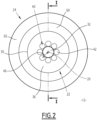
Figure 2 is a front view of the rotor ofFigure 1 . -
Figure 1 is a schematic view of aninduction motor 10 according to an embodiment of the invention. Preferably, themotor 10 is a traction motor of a railway vehicle (not shown). - As shown on
Figure 1 , themotor 10 comprises arotor 12, astator 14 and amotor frame 16. - The
rotor 12 extends along amain axis 20 and comprises arotor shaft 22 and arotor assembly 24. - The
rotor shaft 22 comprises amain body 30 and a first 32 and a second 34 connecting portions, preferably made in one piece. Themain body 30 is axially disposed between the first 32 and second 34 connecting portions. - The
main body 30 has a cylindrical shape and radially projects from the first 32 and second 34 connecting portions. More precisely, themain body 30 comprises a first 36 and a second 38 front faces, substantially plane and perpendicular to themain axis 20. The first 32 and second 34 connecting portions axially protrude, respectively, from the first 36 and from the second 38 front faces. - In the embodiment of
Figures 1 and2 , a junction of each of the first 32 and second 34 connecting portions with themain body 30 is circular, a diameter of said junction being smaller for the first 32 than for the second 34 connecting portion. - Each of the first 32 and second 34 connecting portions of the
rotor shaft 22 is designed for being connected to shaft portions (not shown), so as to form a motor shaft. Said motor shaft is able to rotate relative to theframe 16 around themain axis 20, similarly to the motor described in documentWO2008/022108 . - The
rotor 12 also comprises at least oneventilation channel 40 for cooling said rotor during its rotation. - The
ventilation channel 40 is a tubular cavity extending through themain body 30 of therotor shaft 22. More precisely, theventilation channel 40 extends between a first 42 and a second 44 openings, situated respectively on the first 36 and on the second 38 front faces of themain body 30. - A first
radial distance 46 between themain axis 20 and thefirst opening 42 is smaller than a secondradial distance 48 between themain axis 20 and thesecond opening 44. - Preferably, the
ventilation channel 40 is substantially rectilinear and extends along achannel axis 50. Thechannel axis 50 is coplanar with themain axis 20 and forms a non-zero angle α with saidmain axis 20. More preferably, the angle α is comprised between 1° and 20°, even more preferably comprised between 5° and 10°. - Preferably, the
ventilation channel 40 has a substantially constant width between the first 42 and second 44 openings. Preferably, theventilation channel 40 has a substantially circular section and each of the first 42 and second 44 openings is substantially circular or oval. - Preferably, the
rotor 12 comprises a plurality ofventilation channels 40, arranged around themain axis 20. More preferably, a number ofventilation channels 40 is comprised between four and twelve. - In the embodiment of
Figures 1 and2 , therotor 12 comprises eightventilation channels 40, arranged regularly around themain axis 20. More precisely, theventilation channels 40 are the image of each other by rotational symmetry around the main axis. - As shown on
Figure 2 , thefirst openings 42 of theventilation channels 40 are arranged in a circle on the firstfront face 36 of themain body 30, around the first connectingportion 32. A radius of the circle formed by thefirst openings 42 is the firstradial distance 46. Thesecond openings 44 are arranged similarly on the secondfront face 38, on a circle whose radius is the secondradial distance 48. - The
rotor assembly 24 is fixed to and extends around themain body 30 of therotor shaft 22. In an embodiment of the invention, therotor assembly 24 comprises arotor core 60 and arotor cage 62. Preferably, therotor core 60 is formed by metal laminations inserted around the cylindrical surface of themain body 30 and piled along themain axis 20. The laminations of therotor core 60 are assembled by therotor cage 62 so as to form a squirrel cage rotor. - The
stator 14 comprises astator core 64 of tubular shape, coaxial with themain axis 20. Thestator core 64 defines acylindrical space 66 receiving therotor assembly 24. - In an embodiment of the invention, the
stator 14 also compriseswinding coils 65 inserted in thestator core 64, similarly as the stator described in documentWO2008/022108 . - The
motor frame 16 is fixed to thestator 14. Preferably, the motor frame comprisesbearings rotor shaft 22 and allowing therotor 12 to rotate relative to themotor frame 16 around themain axis 20, similarly as the motor described in documentWO2008/022108 . - The
motor frame 16 defines a first inner volume 70, receiving therotor 12. In a preferred embodiment of the invention, the motor frame comprisesair vents main body 30 of therotor shaft 22. - In the shown embodiment, the
motor 10 also comprises an inner housing encasing thestator 14 and forming a secondinner volume 75 of themotor frame 16, the first 70 and second 75 inner volumes being separated from each other. According to said embodiment, therotor 12 andstator 14 are thermally and/or hydraulically isolated from each other. - In an embodiment, the
motor 10 also comprises a stator cooling device (not shown). For example, themotor 10 comprises a water cooling device for the stator. - A method for implementing the
motor 10 will now be described. During a rotation of therotor 12, an air pressure near thesecond openings 44 is lower than an air pressure near thefirst openings 42 due to the respective distances between said openings and the rotationmain axis 20. Therefore, anair flow 76 is generated in theventilation channels 40 by the rotation of the rotor. Theair flow 76 ensures a cooling of therotor 12 during working. - In the embodiment wherein the
motor 10 comprisesair vents air flow 76 allows fresh outer air to enter in the first inner volume 70. - Therefore, the
inclined ventilation channels 40 of therotor 12 allow an efficient ventilation of said rotor and of the first inner volume 70 of the motor, without adding a fan to the rotor. - The absence of a fan on the
rotor 12 diminishes the noise level of the workingmotor 10, even in the presence ofair vents motor frame 16 is spared, improving the compactness of the motor.
Claims (11)
- A rotor (12) for an induction motor (10), said rotor comprising :- a rotating rotor shaft (22) extending along a main axis (20), said shaft comprising a main body (30) axially extending between a first and a second ends ;- a rotor assembly (24) fixed to and extending around the main body of the shaft ; and- at least one ventilation channel (40) ;characterized in that the at least one ventilation channel (40) is a tubular cavity extending through the main body (30) of the rotor shaft (22), between a first (42) and a second (44) openings, situated respectively on the first and on the second ends of said main body, a first distance (46) between the main axis and the first opening (42) being inferior to a second distance (48) between the main axis and the second opening (44).
- A rotor according to claim 1, wherein the at least one ventilation channel is substantially rectilinear and extends along a channel axis (50), said channel axis being coplanar with the main axis (20) and forming a non-zero angle (α) with said main axis.
- A rotor according to claim 2, wherein the angle (α) is comprised between 1° and 20°, preferably comprised between 5° and 10°.
- A rotor according to one of the preceding claims, comprising a plurality of ventilation channels (40), each ventilation channel being a tubular cavity extending through the main body of the shaft between the first and the second ends of said main body (30), the ventilation channels being arranged around the main axis (20).
- A rotor according to claim 4 combined with claim 2 or 3, wherein each ventilation channel is substantially rectilinear and extends along a channel axis (50), each channel axis being coplanar with the main axis and forming a non-zero angle (α) with said main axis.
- A rotor according to one of the preceding claims, wherein each of the first and second ends of the main body comprise a front face (36, 38) substantially perpendicular to the main axis (20), the first (42) and second (44) openings being situated on the front face, respectively, of said first and of said second ends.
- A rotor according to claim 6, wherein the rotor shaft (22) also comprises a first (32) and a second (34) connecting parts, axially protruding from the front face (36, 38), respectively, of the first and of the second ends of the main body.
- A rotor according to one of the preceding claims, wherein the rotor assembly (24) comprises a rotor core (60), inserted around the main body (30) of the rotor shaft (22) and a rotor cage (62) encasing the rotor core.
- An induction motor (10) comprising :- a rotor (12) according to one of the previous claims ;- a stator (14) coupled to the rotor ; and- a motor frame (16) fixed to the stator, the rotor being able to rotate relative to the motor frame around the main axis (20).
- An induction motor according to claim 9, wherein the motor frame (16) comprises air vents (72, 74) allowing passage for an air flux (76) formed through the at least one ventilation channel (40) by the rotation of the rotor (12).
- A railway vehicle comprising an induction motor (10) according to claim 9 or 10.
Priority Applications (1)
| Application Number | Priority Date | Filing Date | Title |
|---|---|---|---|
| EP23306918.6A EP4550633A1 (en) | 2023-11-06 | 2023-11-06 | Air-cooled rotor for an induction motor |
Applications Claiming Priority (1)
| Application Number | Priority Date | Filing Date | Title |
|---|---|---|---|
| EP23306918.6A EP4550633A1 (en) | 2023-11-06 | 2023-11-06 | Air-cooled rotor for an induction motor |
Publications (1)
| Publication Number | Publication Date |
|---|---|
| EP4550633A1 true EP4550633A1 (en) | 2025-05-07 |
Family
ID=88969490
Family Applications (1)
| Application Number | Title | Priority Date | Filing Date |
|---|---|---|---|
| EP23306918.6A Pending EP4550633A1 (en) | 2023-11-06 | 2023-11-06 | Air-cooled rotor for an induction motor |
Country Status (1)
| Country | Link |
|---|---|
| EP (1) | EP4550633A1 (en) |
Citations (4)
| Publication number | Priority date | Publication date | Assignee | Title |
|---|---|---|---|---|
| JP3266768B2 (en) * | 1995-08-28 | 2002-03-18 | 三菱電機株式会社 | Cage induction motor rotor and cage induction motor |
| WO2008022108A2 (en) | 2006-08-15 | 2008-02-21 | Bombardier Transportation Gmbh | Semi-enclosed ac motor |
| US20190363609A1 (en) * | 2017-02-14 | 2019-11-28 | Bayerische Motoren Werke Aktiengesellschaft | Rotor Shaft for an Electric Machine and Electric Machine |
| CN110535290A (en) * | 2019-09-26 | 2019-12-03 | 苏州保邦电气有限公司 | Parallel air-cooled circulation system for ultra-high-speed motors |
-
2023
- 2023-11-06 EP EP23306918.6A patent/EP4550633A1/en active Pending
Patent Citations (4)
| Publication number | Priority date | Publication date | Assignee | Title |
|---|---|---|---|---|
| JP3266768B2 (en) * | 1995-08-28 | 2002-03-18 | 三菱電機株式会社 | Cage induction motor rotor and cage induction motor |
| WO2008022108A2 (en) | 2006-08-15 | 2008-02-21 | Bombardier Transportation Gmbh | Semi-enclosed ac motor |
| US20190363609A1 (en) * | 2017-02-14 | 2019-11-28 | Bayerische Motoren Werke Aktiengesellschaft | Rotor Shaft for an Electric Machine and Electric Machine |
| CN110535290A (en) * | 2019-09-26 | 2019-12-03 | 苏州保邦电气有限公司 | Parallel air-cooled circulation system for ultra-high-speed motors |
Similar Documents
| Publication | Publication Date | Title |
|---|---|---|
| US12592606B2 (en) | Axial flux motor with air cooling system | |
| US8016574B2 (en) | Cooling fan for a motor vehicle | |
| US8487490B2 (en) | Electric rotating machine | |
| US5644179A (en) | Gas cooled end turns for dynamoelectric machine rotor | |
| JP6818869B2 (en) | Electric motor and blower | |
| US10544789B2 (en) | Axial flux electrical motor and fan assembly and methods of assembling the same | |
| JP6376981B2 (en) | Rotating device | |
| CN112117858A (en) | Motor with cooling structure | |
| KR101563314B1 (en) | Open type motor | |
| CN108365703B (en) | Motor air-cooled impeller, double-air-channel motor and electric vehicle | |
| CN110535290A (en) | Parallel air-cooled circulation system for ultra-high-speed motors | |
| US12407221B2 (en) | Air flow control apparatus | |
| JP2021121144A (en) | Rotor for rotary electric machine | |
| JP2008043149A (en) | Motor cooling structure | |
| JPH07241059A (en) | Rotating electric machine | |
| JP2019022257A (en) | Rotary electric machine | |
| US20250357820A1 (en) | Electric traction motor for a vehicle, with a cooling device | |
| KR19980087479A (en) | Rotary electric machine | |
| JP2006340571A (en) | Electric motor for vehicle | |
| JPH09182372A (en) | Main electric motor for railway vehicles | |
| KR101758989B1 (en) | rotor assembly for generator | |
| JP2008035584A (en) | Self-ventilated cooling rotary electric machine for vehicles | |
| JPH07170693A (en) | Rotating machine rotor | |
| JP7249731B2 (en) | Design Method of Totally Enclosed Rotating Electric Machine | |
| JP2026075268A (en) | Rotor |
Legal Events
| Date | Code | Title | Description |
|---|---|---|---|
| PUAI | Public reference made under article 153(3) epc to a published international application that has entered the european phase |
Free format text: ORIGINAL CODE: 0009012 |
|
| STAA | Information on the status of an ep patent application or granted ep patent |
Free format text: STATUS: THE APPLICATION HAS BEEN PUBLISHED |
|
| AK | Designated contracting states |
Kind code of ref document: A1 Designated state(s): AL AT BE BG CH CY CZ DE DK EE ES FI FR GB GR HR HU IE IS IT LI LT LU LV MC ME MK MT NL NO PL PT RO RS SE SI SK SM TR |
|
| STAA | Information on the status of an ep patent application or granted ep patent |
Free format text: STATUS: REQUEST FOR EXAMINATION WAS MADE |
|
| 17P | Request for examination filed |
Effective date: 20251028 |