EP4550621A1 - Battery-powered electric mining equipment - Google Patents
Battery-powered electric mining equipment Download PDFInfo
- Publication number
- EP4550621A1 EP4550621A1 EP23207848.5A EP23207848A EP4550621A1 EP 4550621 A1 EP4550621 A1 EP 4550621A1 EP 23207848 A EP23207848 A EP 23207848A EP 4550621 A1 EP4550621 A1 EP 4550621A1
- Authority
- EP
- European Patent Office
- Prior art keywords
- circuitry
- primary
- electric equipment
- voltage
- tapping points
- Prior art date
- Legal status (The legal status is an assumption and is not a legal conclusion. Google has not performed a legal analysis and makes no representation as to the accuracy of the status listed.)
- Pending
Links
Images




Classifications
-
- H—ELECTRICITY
- H02—GENERATION; CONVERSION OR DISTRIBUTION OF ELECTRIC POWER
- H02J—ELECTRIC POWER NETWORKS; CIRCUIT ARRANGEMENTS OR SYSTEMS FOR SUPPLYING OR DISTRIBUTING ELECTRIC POWER; SYSTEMS FOR STORING ELECTRIC ENERGY
- H02J7/00—Circuit arrangements for charging or discharging batteries or for supplying loads from batteries
- H02J7/02—Circuit arrangements for charging or discharging batteries or for supplying loads from batteries for charging batteries from AC mains by converters
-
- H—ELECTRICITY
- H02—GENERATION; CONVERSION OR DISTRIBUTION OF ELECTRIC POWER
- H02J—ELECTRIC POWER NETWORKS; CIRCUIT ARRANGEMENTS OR SYSTEMS FOR SUPPLYING OR DISTRIBUTING ELECTRIC POWER; SYSTEMS FOR STORING ELECTRIC ENERGY
- H02J7/00—Circuit arrangements for charging or discharging batteries or for supplying loads from batteries
- H02J7/34—Parallel operation in networks using both storage and other DC sources, e.g. providing buffering
-
- H—ELECTRICITY
- H02—GENERATION; CONVERSION OR DISTRIBUTION OF ELECTRIC POWER
- H02M—APPARATUS FOR CONVERSION BETWEEN AC AND AC, BETWEEN AC AND DC, OR BETWEEN DC AND DC, AND FOR USE WITH MAINS OR SIMILAR POWER SUPPLY SYSTEMS; CONVERSION OF DC OR AC INPUT POWER INTO SURGE OUTPUT POWER; CONTROL OR REGULATION THEREOF
- H02M5/00—Conversion of AC power input into AC power output, e.g. for change of voltage, for change of frequency, for change of number of phases
- H02M5/02—Conversion of AC power input into AC power output, e.g. for change of voltage, for change of frequency, for change of number of phases without intermediate conversion into DC
- H02M5/04—Conversion of AC power input into AC power output, e.g. for change of voltage, for change of frequency, for change of number of phases without intermediate conversion into DC by static converters
- H02M5/10—Conversion of AC power input into AC power output, e.g. for change of voltage, for change of frequency, for change of number of phases without intermediate conversion into DC by static converters using transformers
- H02M5/12—Conversion of AC power input into AC power output, e.g. for change of voltage, for change of frequency, for change of number of phases without intermediate conversion into DC by static converters using transformers for conversion of voltage or current amplitude only
-
- H—ELECTRICITY
- H02—GENERATION; CONVERSION OR DISTRIBUTION OF ELECTRIC POWER
- H02J—ELECTRIC POWER NETWORKS; CIRCUIT ARRANGEMENTS OR SYSTEMS FOR SUPPLYING OR DISTRIBUTING ELECTRIC POWER; SYSTEMS FOR STORING ELECTRIC ENERGY
- H02J2207/00—Details of circuit arrangements for charging or discharging batteries or supplying loads from batteries
- H02J2207/20—Charging or discharging characterised by the power electronics converter
Definitions
- This disclosure relates to a battery-powered electric equipment, such as a battery-powered electric mining equipment used in a mining environment.
- the three-phase voltage in mining environments typically varies within a range of 380 to 1000Vac and between 50Hz and 60 Hz.
- an electric equipment such as a mining equipment, may be equipped with a (sometimes called) multi-voltage supply transformer, which can be an autotransformer.
- a battery-powered electric equipment further requires a charging transformer.
- the multi-voltage transformer and the charging transformer take up a lot of space, making the electric equipment heavy and bulky.
- Example embodiments of the present disclosure provide a compact and/or lightweight battery-powered electric equipment.
- the battery-powered electric equipment can be a battery-powered mining equipment used in a mining environment, such as a drill rig.
- an electric equipment comprises a first circuitry, a second circuitry, and a transformer.
- the first circuitry comprises a motor.
- the second circuitry comprises a rechargeable battery.
- the transformer comprises a primary side comprising a plurality of sets of primary tapping points, and a secondary side electrically isolated from the primary side.
- the primary side is configured to be connected to an electrical network.
- the first circuitry is configured to be connected to the primary side.
- the first circuitry is switchable between at least two of the sets of primary tapping points.
- the second circuitry is configured to be connected to the secondary side.
- the primary side acts both as an autotransformer configured to convert the grid voltage into the first circuitry voltage, and as the primary side of a two-side transformer configured to convert the grid voltage into the second circuitry voltage.
- the primary side acts as a multi-voltage autotransformer configured to convert different grid voltages into a first circuitry voltage at the rated voltage of the first circuitry.
- the primary side and the secondary side form together a multi-voltage transformer configured to convert different grid voltages into a second circuitry voltage at the rated voltage of the second circuitry.
- the transformer has thus both a multi-voltage autotransformer and a multi-voltage charging transformer functionalities.
- the transformer can thus replace both a multi-voltage transformer and a charging transformer. This allows the equipment to be more compact and lightweight.
- the primary side is a three-phase primary side comprising: three primary windings, each set of primary tapping points comprising one tapping point on each primary winding.
- the first circuitry is further switchable to be directly connected to the electrical network.
- the first circuitry is configured to be switched to one of the sets of primary tapping points providing a first circuitry voltage at a rated voltage of the first circuitry.
- the first circuitry is configured to be switched between the at least two of the sets of primary tapping points based on a level of a grid voltage provided by the electrical network.
- a connection between the primary side and the electrical network is switchable between at least two of the sets of primary tapping points.
- connection between the primary side and the electrical network is configured to be switched between the at least two of the sets of primary tapping points based on a level of a grid voltage provided by the electrical network.
- the secondary side comprises at least one set of secondary tapping points.
- the secondary side comprises a plurality of sets of secondary tapping points; and wherein the second circuitry is switchable between at least two of the sets of secondary tapping points.
- the secondary side is a three-phase secondary side comprising three secondary windings, each set of secondary tapping points comprising one tapping point on each secondary winding.
- the second circuitry is configured to be switched between the at least two of the sets of secondary tapping points based on a level of a grid voltage provided by the electrical network.
- the motor comprises at least one drilling powerpack motor.
- the second circuitry comprises at least one tramming motor.
- the second circuitry comprises a three-phase capacitor filter with inverter side chokes.
- the second circuitry comprises an AC/DC rectifier (or inverter), wherein the rechargeable battery is configured to be connected to the secondary side via the AC/DC rectifier (or inverter).
- the second circuitry comprises one or more secondary motor configured to operate one or more of: a compressor; a water booster pump; or an auxiliary power unit.
- the primary side is arranged in a delta-connection or in a wye-connection
- the secondary side is arranged in a delta-connection or in a wye-connection
- FIG. 1 illustrates a conventional battery-powered electric equipment 100.
- the conventional battery-powered equipment 100 comprises a motor 103, a rechargeable battery 104 and a charging circuit 105 for charging the rechargeable battery 104.
- the charging circuit 105 typically comprises a power converter or inverter.
- the conventional battery-powered electric equipment 100 may be a battery-powered mining equipment, such as a mining drill rig used in a mining environment.
- the conventional electric equipment 100 comprises a multi-voltage autotransformer 101 (e.g., dimensioned for 230kVA) .
- the multi-voltage transformer 101 is configured to convert the grid voltage provided by an electrical network 102, for example, an electric grid of a mining site, into an operating voltage at the rated voltage of the motor 103 (e.g., 380-480V or 690V).
- the charging circuit 105 typically operates at a lower voltage than the motor 103.
- the conventional electric equipment 100 thus further comprises a charging transformer 107 (e.g., dimensioned for 100kVA) configured to convert the output voltage of the multi-voltage transformer 101 into a charging voltage used to charge the rechargeable battery 104.
- the charging circuit 105 typically operates in direct current (DC), while the grid voltage provided by the electrical network 102 is typically alternating current (AC).
- the charging transformer 107 provides galvanic isolation between the DC-circuit and the AC-side.
- the charging transformer 107 may further comprise a filter.
- the conventional electric equipment 100 thus requires two transformers 101 and 107. These two transformers 101 and 107 take up space, making the conventional equipment 100 bulky and heavy. This is particularly problematic when the equipment is a mining equipment such as a mining drill rig.
- FIG. 2 illustrates an electric equipment 200 according to an example embodiment.
- the electric equipment 200 comprises a first circuitry 210, a second circuitry 220, and transformer 230.
- a "circuitry” may be defined as a system of electrical circuits.
- the first circuitry 210 and the second circuitry 220 may each be defined as a sub-system of the electric equipment 200.
- the first circuitry 210 comprises at least one electric motor 203.
- the electric motor 203 can be powered by the electrical network 202, for example, an electrical network of a mining site, when the electric equipment 200 is connected to the electrical network 202.
- the electric motor 203 can be powered by the rechargeable battery 204, in particular when the electric equipment 200 is not connected to the electrical network 202.
- the first circuitry 210 must generally be operated at a rated voltage for reliable operation.
- the rated voltage refers to a voltage range at which a device or machine is designed to operate reliably.
- the rated voltage of the first circuitry 210 may be defined by the rated voltage of the electric motor 203 (e.g., 380-480V or 690V).
- the second circuitry 220 comprises at least one rechargeable battery 204, also called storage battery.
- the rechargeable battery 204 is an electrical battery which can be charged, discharged into a load, and recharged many times.
- the second circuitry 220 comprises a battery charger 205 configured to charge the rechargeable battery 204.
- the battery charger 205 may comprise a rectifier configured to convert alternating current (AC) (e.g., 350V AC) to direct current (DC) (e.g., 600V DC) .
- the second circuitry 220 may further comprise one or more electric motors or other electric equipment.
- the second circuitry 220 must generally be operated at a rated voltage for reliable operation.
- the rated voltage of the second circuitry 210 may be defined by the rated AC voltage of the battery charger 205 (e.g., 350V AC) and/or the rated DC charging voltage of the rechargeable battery 204 (e.g., 600V DC).
- the charging voltage must be higher than that of the battery to force current to flow into it, but not too much higher or the battery may be damaged.
- the transformer 230 has both multi-voltage transformer and charging transformer functionalities.
- the transformer 230 thus replaces both the multi-voltage transformer 101 and charging transformer 107 of the conventional equipment 100. This may allow the equipment 200 to be more compact and lightweight.
- the transformer 230 comprises a primary side 231 and a secondary side 232.
- the primary side 231 and secondary side 232 are electrically isolated from each other but may be magnetically coupled through a common core.
- the common core may be a closed magnetic iron circuit.
- the core may be a soft iron core made up of individual laminations connected together.
- the primary side 231 can be connected to the electrical network 202 (e.g., via an electrical network connection point 235) to receive the grid voltage provided by the electrical network 202.
- the primary side 231 is connected to the first circuitry 210 (e.g., via a first circuitry connection point 215) and configured to provide a first circuitry voltage to the first circuitry 210.
- the secondary side 232 is connected to the second circuitry 220 (e.g., via a second circuitry connection point 225) and configured to provide a second circuitry voltage to the second circuitry 220.
- the primary side 231 acts both as an autotransformer configured to convert the grid voltage into the first circuitry voltage, and as the primary side of a two-side transformer configured to convert the grid voltage into the second circuitry voltage.
- the charging circuit 220 typically operates in DC, while the grid voltage provided by the electrical network 202 is typically AC.
- the secondary side 232 provides galvanic isolation between the DC-circuit of the second circuitry 220 and the AC-side.
- the primary side 231 acts as a multi-voltage autotransformer configured to convert different grid voltages into a first circuitry voltage at the rated voltage of the first circuitry.
- the primary side 231 and the secondary side 232 form together a multi-voltage transformer configured to convert different grid voltages into a second circuitry voltage at the rated voltage of the second circuitry.
- the primary side 231 may be dimensioned for the first circuitry (e.g., 230kVA), while the secondary side 232 may be dimensioned for the second circuitry (e.g., 100kVA) .
- Simultaneous load sharing may be done according to different prioritization strategies, for example based on the temperatures of the primary and secondary windings.
- the primary side 231 comprises at least two set 311A, 311B, 311C of primary tapping points. Each set 311A, 311B, 311C of primary tapping points provides a different voltage.
- FIG. 2 Three sets 311A, 311B, 311C of primary tapping points are illustrated on FIG. 2 , but it is understood that the primary side 231 may comprise any number of sets of primary tapping points, for example up to 100 sets of primary tapping points.
- each set 311A, 311B, 311C of primary tapping points comprises one tapping point on each of the primary winding 311-i.
- the set of primary tapping points 311B comprises tapping point 311B-1 on the first primary winding 311-1, tapping point 311B-2 on the second primary winding 311-2, and tapping point 311B-3 on the third primary winding 311-3.
- the first circuitry 210 can be connected to the primary side 231 via (alternately) any one of (at least some of) the sets 311A, 311B, 311C of primary tapping points.
- the connection point 215 can be switched between (at least some of) the various sets 311A, 311B, 311C of primary tapping points.
- Each set 311A, 311B, 311C of primary tapping points provides a different ratio of the grid voltage to the first circuitry 210.
- the first circuitry 210 can be connected to one of the sets 311A, 311B, or 311C that provides a first circuitry voltage that is at the rated voltage of the first circuitry (e.g., rated voltage of the motor 203).
- a different one of the sets 311A, 311B, or 311C can be selected to be connected to the first circuitry 210.
- the primary side 231 thus acts as a multi-voltage autotransformer configured to convert different grid voltages into a first circuitry voltage at the rated voltage of the first circuitry.
- the first circuitry 210 may be driven directly by the electrical network 202. To that end, the first circuitry 210 is connected to the electrical network 202 directly (as opposed to via the transformer 230).
- the primary side 231 can be connected to the electrical network 202 via (alternately) any one of (at least some of) the various sets 311A, 311B, 311C of primary tapping points.
- the connection point 235 between the primary side 231 and the electrical network 202 can be switched between (at least some of) the various sets of primary tapping points 311A, 311B, 311C.
- the first circuitry voltage depends on which set of primary tapping points is connected to the electrical network 202 and/or which set of primary tapping points is connected to the first circuitry 210.
- the set of primary tapping points to be connected to the electrical network 202 and/or the set of primary tapping points to be connected to the first circuitry 210 may be selected such that the first circuitry voltage is at the rated voltage of the first circuitry.
- the secondary side 232 may comprise at least one set 312a, 312b of secondary tapping points.
- FIG. 2 Two sets 312a, 312b of secondary tapping points are illustrated on FIG. 2 . It is however understood that the secondary side 232 may comprise any number of sets of secondary tapping points, for example up to 100 sets.
- the second circuitry 220 can be connected to the secondary side 232 via (alternately) any one of (at least some of) the sets 312a, 312b of secondary tapping points.
- the connection point 225 between the secondary side 232 and the second circuitry 220 can be switched between (at least some of) the various sets 312a, 312b of secondary tapping points.
- Each set 312a, 312b of secondary tapping points provides a different ratio of the grid voltage.
- the second circuitry 220 can be connected to one of the sets 312a, 312b providing a voltage at the rated voltage of the second circuitry (e.g., rated voltage of the battery). Depending on the grid voltage provided by the electrical network 202, a different one of the sets 312a, 312b can be selected to be connected to the second circuitry 220.
- the primary side 231 and the secondary side 232 thus form together a multi-voltage transformer configured to convert different grid voltages into a second circuitry voltage at the rated voltage of the second circuitry 220.
- the second circuitry voltage depends on the set of primary tapping points connected to the electrical network 202 and/or the set of secondary tapping points connected to the second circuitry 220.
- the set of primary tapping points to be connected to the electrical network 202 and/or the set of secondary tapping points to be connected to the second circuitry 220 can be selected such that the second circuitry voltage is at the rated voltage of the second circuitry (e.g., rated voltage of the charging circuit 220).
- the transformer 230 may comprise a tap changer 250.
- the tap changer 250 is configured to switch the first circuitry 210 (e.g., connection point 215) between (at least some of) the various sets of primary tapping points 311A, 311B, 311C, and optionally connection point 235.
- the tap changer 250 may be configured to select one of the sets of primary tapping points 311A, 311B, 311C, (or connection point 235) based on a grid voltage provided by the electrical network 202. More specifically, the tap changer 250 may be configured to select a set of primary tapping points 311A, 311B, 311C, (or connection point 235) that provides a ratio of the grid voltage that is at the rated voltage of the first circuitry 210.
- the tap changer 250 may be further configured to switch the electrical network 202 (e.g., connection point 235) between (at least some of) the various sets of primary tapping points 311A, 311B, 311C.
- the tap changer 250 may be configured to select one of the sets of primary tapping points 311A, 311B, 311C, or connection point 235 based on a grid voltage provided by the electrical network 202. More specifically, the tap changer 250 may be configured to select a set of primary tapping points 311A, 311B, 311C, (or connection point 235) such that the first circuitry voltage is at the rated voltage of the first circuitry and/or such that the second circuitry voltage is at the rated voltage of the second circuitry.
- the tap changer 250 may be further configured to switch the second circuitry 220 (e.g., connection point 225) between (at least some of) the various sets of secondary tapping points 312a, 312b.
- the tap changer 250 may be configured to select one of the sets of secondary tapping points 312a, 312b based on a grid voltage provided by the electrical network 202. More specifically, the tap changer 250 may be configured to select a set of secondary tapping points 312a, 312b that provides a ratio of the grid voltage that is at the rated voltage of the second circuitry 220.
- the process of selecting and/or switching between sets of tapping points may be a manual operation, electronically assisted, or fully electronic.
- a control unit may measure the grid voltage and automatically selects a primary tapping point for the first circuitry and/or a secondary tapping point for the second circuitry.
- FIG. 3A illustrates an example embodiment of the transformer 230 as a three-phase transformer.
- the transformer 230 may be a three-phase transformer.
- a three-phase grid voltage is provided by the electrical network 202.
- Three-phase power systems are common where high power is required, such as large induction motors, other types of electric motors and demanding loads, such as some mining equipment such as a drill rig.
- the primary side 231 comprises three primary windings 311-1, 311-2, 311-3 (collectively referred as primary windings 311-i, where i can be 1, 2, and 3).
- the secondary side 232 comprises three secondary windings 312-1, 312-2, 312-3 (collectively referred as secondary windings 312-i, where i can be 1, 2, and 3).
- the three primary windings 311-1, 311-2, 311-3 and three secondary windings 312-1, 312-2, 312-3 form three pairs of primary and secondary windings.
- the three pairs of primary and secondary windings may be mounted onto one single common core.
- Each pair of primary 311-i and secondary 312-i windings are electrically isolated from each other but magnetically coupled through the common core allowing electrical power to be transferred from the primary winding 311-i to the secondary winding 312-i.
- a magnetic field is generated which induces a voltage into the secondary winding 312-i.
- the primary 311-i and secondary 312-i windings can be connected in different configuration, e.g., star (wye), delta (mesh) or interconnected-star (zig-zag).
- the combinations of the three windings may be with the primary winding delta-connected and the secondary windings star-connected, or star-delta, star-star or delta-delta, depending on the transformers use.
- the primary 311 can be in a YanO configuration, and the secondary 312 in a Yyn0 configuration.
- YanO refers to autotransformer connection and Yyn0 refers to isolation transformer connection (e.g., the charging transformer).
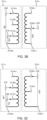
- FIG. 3B and 3C illustrate an example embodiment of one primary winding 311-i and one secondary winding 312-i. i can be 1, 2, and 3.
- Each primary 311-i and secondary 312-i winding comprises a wire made of electrical conductor (e.g., copper) wrapped around a section of the common core.
- electrical conductor e.g., copper
- Each primary winding 311-i comprises at least two primary tapping points.
- a tapping point is an electrical connection point where an external circuit can be connected to the winding.
- Each primary winding 311-i comprises a terminal point 311N-i and 311A-i at each end of the primary winding 311-i, and one or more intermediate tapping points 311B-i, 311C-i along the length of the primary winding 311-i.
- Terminal point 311A-i may be a terminal tapping point.
- Different tapping points 311A-i, 311B-i, 311C-i along the primary winding 311-i correspond to different voltages, measured from the common terminal point 311N-i.
- each primary winding 311-i comprises a primary terminal tapping point 311A-i, a first intermediate primary tapping point 311B-i, and a second intermediate tapping point 311C-i. It is however understood that each primary winding 311-i may comprise any number of tapping points, for example up to 100 tapping points.
- Both the electrical network 202 and the first circuitry 210 may be connected in common to terminal point 311N-i.
- the other terminal of the electrical network 202 is connected to one of the tapping points (e.g., 311A-i, 311B-i, or 311C-i).
- the other terminal of the first circuitry 210 is connected to another one of the tapping points (e.g., 311A-i, 311B-i, or 311C-i) .
- Each secondary winding 312-i may comprise at least one secondary tapping point.
- Each secondary winding 312-i comprises a terminal point 312a-i and 311n-i at each end of the secondary winding 312-i.
- Each secondary winding 312-i may further comprise one or more intermediate tapping points 312b-i along the length of the secondary winding 312-i.
- Terminal point 312a-i may be a terminal tapping point.
- Different tapping points 312a-i, 312b-i along the secondary winding 312-i correspond to different voltages, measured from terminal point 312n-i.
- each secondary winding 312-i comprises a secondary terminal point 312a-i, and a secondary intermediate tapping point 312b-i. It is however understood that each secondary winding 312-i may comprise any number of secondary tapping points, for example up to 100 secondary tapping points.
- the second circuitry 220 can be connected across terminal point 312n-i and one of the secondary tapping points 312a-i, 312b-i.
- the primary side 311 may function as a step-down autotransformer configured to step-down the grid voltage Vg to provide a lower first circuitry voltage Vp1 to the first circuitry.
- the electrical network 202 may be connected across a larger portion of the primary winding 311-i (e.g., connection point 235 connected to tapping point 311A-I, or 311B-i), while the first circuitry 210 is connected across a smaller portion of the primary winding 311-i (e.g., connection point 215 connected to tapping point 311C-1).
- the larger portion of the primary winding 311-i can be the entire primary winding 311-i (e.g., connection point 235 connected to terminal tapping point 311A-i).
- the primary side 311 may function as a step-up autotransformer configured to step-up the grid voltage Vg to provide a higher first circuitry voltage Vp1 to the first circuitry.
- the first circuitry 210 may be connected across a larger portion of the primary winding 311-i (e.g., connection point 215 connected to a tapping point 311A-i, or 311B-i), while the electrical network 202 is connected across a smaller portion of the primary winding 311-i (e.g., connection point 235 connected to tapping point 311C-i).
- the ratio of first circuitry voltage Vp1 to grid voltage Vg is equal to the ratio of the length (or number of turns of winding) of the portion of the primary winding across which the first circuitry 210 is connected to the length of the portion of the primary winding across which the electrical network 202 is connected.
- the primary side 311 and secondary side 312 may function together as a step-down transformer configured to step-down the grid voltage Vg to provide a lower second circuitry voltage Vp2 to the second circuitry.
- the second circuitry 220 may be connected across a smaller portion of the secondary winding 312-i (e.g., connection point 225 connected to tapping point 312b-i), while the electrical network 202 is connected across a larger portion of the primary winding 311-i (e.g., connection point 235 connected to tapping point 311A-i or 311B-i).
- the primary side 311 and secondary side 312 may function together as a step-up transformer configured to step-up the grid voltage Vg to provide a higher second circuitry voltage Vp2 to the second circuitry.
- the second circuitry 220 may be connected across a larger portion of the secondary winding 312-i (e.g., connection point 225 connected to tapping point 312a-i), while the electrical network 202 is connected across a smaller portion of the primary winding 311-i (e.g., connection point 235 connected to tapping point 311C-i or 311B-i).
- the larger portion of the secondary winding 312-i can be the entire secondary winding 312-i (e.g., connection point 225 connected to terminal point 312a-i).
- the ratio of second circuitry voltage Vp2 to grid voltage Vg is equal to the ratio of the length (or number of turns of winding) of the portion of the secondary winding across which the second circuitry 220 is connected to the length of the portion of the primary winding across which the electrical network 202 is connected.
- the transformer 230 may be liquid-cooled.
- the transformer 230 may be placed in an enclosure filled with liquid (e.g., transformer oil) that both cools and insulates the windings.
- liquid e.g., transformer oil
- Liquid cooling may also be arranged in a way where cooling media and the cooled part of the transformer (e.g., the coils) are not in direct contact. Liquid cooling is convenient since there are already other liquid cooled components in the system.
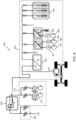
- FIG. 4 illustrates an example embodiment of the electric equipment 200 as a mining equipment 400 such as an underground drill rig 400.
- An underground drilling rig is a system or machine that drills holes under the ground, e.g., for hole drilling in underground mining and tunneling. Drilling rigs can be mobile equipment mounted on a vehicle (such as a truck), on tracks or on trailers.
- the transformer 230 may be connected to the electrical network 202 via one or more inputs controlled by switches at 430, which may further comprise additional electrical components such as fuses, etc.
- the first circuitry 210 may comprise one or more powerpack motors 412, e.g., configured to operate one or more electric-powered hydraulic powerpacks.
- An electric-powered hydraulic powerpack is a system or machine that converts electricity to hydraulic energy.
- An electric-powered hydraulic powerpack typically produce a hydraulic fluid flow, which can be maintained at a pressure.
- the second circuitry 220 may comprise at least one tramming motor 422, e.g., configured to supply the power for moving or tramming the machine.
- the second circuitry 220 may comprise a rectifier or AC/DC converter 424.
- the rechargeable battery 204 is connected to the secondary side 232 via the AC/DC converter 424.
- the second circuitry 220 may comprise one or more secondary electric motors, such as electric motor 427 configured to operate a compressor 437, electric motor 428 configured to operate a water booster pump 438 and/or electric motor 429 configured to operate an auxiliary power unit 439. If connected behind the rectifier 424, the secondary electric motors 427, 428, 429 may be connected to the rectifier 424 via an inverter or DC/AC converter 424.
- the second circuitry 220 may comprise one or more additional components connected to the DC link of the rectifier 424, such as e.g., a heater, an on-board slow charger, an air-conditioning compressor.
- Electric equipment in the first circuitry e.g., powerpack motors 412) and/or electric equipment in the second circuitry (e.g., electric motor 427, 428, 429) can be powered by the electrical network 202, for example, an electrical network of a mining site, when the mining equipment 400 is connected to the electrical network 202.
- Electric equipment in the first circuitry e.g., powerpack motors 412) and/or electric equipment in the second circuitry (e.g., electric motor 427, 428, 429) can be powered by the rechargeable battery 204, e.g., when the electric equipment 200 is not connected to the electrical network 202.
- the combined transformer 230 takes up less space than the multi-voltage transformer 101 and charging transformer 107 of the conventional equipment 100. This frees up some space thereby allowing the use of a larger number of powerpacks and/or larger powerpacks in a drill rig.
- the combined transformer 230 allows for the separation of the powerpack motors 412 from the tramming motors 422. This offers major benefits to commonality between different sized drill rigs and between different applications.
- one larger combined transformer e.g., transformer 230
- two separate transformers e.g., multi-voltage transformer 101 and charging transformer 107
- This also means better component utilization.
- the conventional equipment 100 leaves the multi-voltage transformer 101 unused.
- FIG. 5 illustrates an example embodiment of the transformer 230, wherein the primary side 231 is arranged in a wye-connection, and the secondary side 232 is arranged in a wye-connection.
- the three primary windings 311-1, 311-2, 311-3 are connected at a common neutral point 311N.
- the three secondary windings 312-1, 312-2, 312-3 are connected at a common neutral point 312n.
- FIG. 6 illustrates an example embodiment of the transformer 230, wherein the primary side 231 is configured in a wye-connection and the secondary side 232 is configured in a delta-connection.
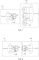
- FIG. 7 illustrates an example embodiment of the transformer 230, wherein the primary side 231 is configured in a delta-connection and the secondary side 232 is configured in a wye-connection.
- FIG. 8 illustrates an example embodiment of the transformer 230, wherein both the primary side 231 and the secondary side 232 are arranged in delta-connection.
- FIG. 9 illustrates an example embodiment of the transformer 230 comprising a three-phase capacitor filter circuit 340 on the secondary side 232.
- a 550 Volt three-phase voltage from an electrical network 202 may be provided to primary tapping point 311C, which may yield a 658 Volt output voltage on primary tapping point 311B.
- 332 Volt output voltage may be available on secondary terminal point 312a.
- subjects may be referred to as 'first' or 'second' subjects, this does not necessarily indicate any order or importance of the subjects. Instead, such attributes may be used solely for the purpose of making a difference between subjects.
Landscapes
- Engineering & Computer Science (AREA)
- Power Engineering (AREA)
- Ac-Ac Conversion (AREA)
Abstract
Description
- This disclosure relates to a battery-powered electric equipment, such as a battery-powered electric mining equipment used in a mining environment.
- Electrical grids around the world supply electricity at different voltage levels. For example, the three-phase voltage in mining environments typically varies within a range of 380 to 1000Vac and between 50Hz and 60 Hz.
- To fit different grid voltages, an electric equipment, such as a mining equipment, may be equipped with a (sometimes called) multi-voltage supply transformer, which can be an autotransformer. A battery-powered electric equipment further requires a charging transformer.
- The multi-voltage transformer and the charging transformer take up a lot of space, making the electric equipment heavy and bulky.
- This summary is provided to introduce a selection of concepts in a simplified form that are further described below in the detailed description. This summary is not intended to identify key features or essential features of the claimed subject matter, nor is it intended to be used to limit the scope of the claimed subject matter.
- Example embodiments of the present disclosure provide a compact and/or lightweight battery-powered electric equipment. The battery-powered electric equipment can be a battery-powered mining equipment used in a mining environment, such as a drill rig.
- According to a first aspect, an electric equipment comprises a first circuitry, a second circuitry, and a transformer. The first circuitry comprises a motor. The second circuitry comprises a rechargeable battery. The transformer comprises a primary side comprising a plurality of sets of primary tapping points, and a secondary side electrically isolated from the primary side. The primary side is configured to be connected to an electrical network. The first circuitry is configured to be connected to the primary side. The first circuitry is switchable between at least two of the sets of primary tapping points. The second circuitry is configured to be connected to the secondary side.
- The primary side acts both as an autotransformer configured to convert the grid voltage into the first circuitry voltage, and as the primary side of a two-side transformer configured to convert the grid voltage into the second circuitry voltage.
- Further, the primary side acts as a multi-voltage autotransformer configured to convert different grid voltages into a first circuitry voltage at the rated voltage of the first circuitry.
- Further, the primary side and the secondary side form together a multi-voltage transformer configured to convert different grid voltages into a second circuitry voltage at the rated voltage of the second circuitry.
- The transformer has thus both a multi-voltage autotransformer and a multi-voltage charging transformer functionalities. The transformer can thus replace both a multi-voltage transformer and a charging transformer. This allows the equipment to be more compact and lightweight.
- In an example embodiment of electric equipment, alternatively or in addition to the above-mentioned example embodiment, the primary side is a three-phase primary side comprising: three primary windings, each set of primary tapping points comprising one tapping point on each primary winding.
- In an example embodiment of electric equipment, alternatively or in addition to the above-mentioned example embodiments, the first circuitry is further switchable to be directly connected to the electrical network.
- In an example embodiment of electric equipment, alternatively or in addition to the above-mentioned example embodiments, the first circuitry is configured to be switched to one of the sets of primary tapping points providing a first circuitry voltage at a rated voltage of the first circuitry.
- In an example embodiment of electric equipment, alternatively or in addition to the above-mentioned example embodiments, the first circuitry is configured to be switched between the at least two of the sets of primary tapping points based on a level of a grid voltage provided by the electrical network.
- In an example embodiment of electric equipment, alternatively or in addition to the above-mentioned example embodiments, a connection between the primary side and the electrical network is switchable between at least two of the sets of primary tapping points.
- In an example embodiment of electric equipment, alternatively or in addition to the above-mentioned example embodiments, the connection between the primary side and the electrical network is configured to be switched between the at least two of the sets of primary tapping points based on a level of a grid voltage provided by the electrical network.
- In an example embodiment of electric equipment, alternatively or in addition to the above-mentioned example embodiments, the secondary side comprises at least one set of secondary tapping points.
- In an example embodiment of electric equipment, alternatively or in addition to the above-mentioned example embodiments, the secondary side comprises a plurality of sets of secondary tapping points; and wherein the second circuitry is switchable between at least two of the sets of secondary tapping points.
- In an example embodiment of electric equipment, alternatively or in addition to the above-mentioned example embodiments, the secondary side is a three-phase secondary side comprising three secondary windings, each set of secondary tapping points comprising one tapping point on each secondary winding.
- In an example embodiment of electric equipment, alternatively or in addition to the above-mentioned example embodiments, the second circuitry is configured to be switched to one of the sets of secondary tapping points providing a second circuitry voltage at a rated voltage of the second circuitry.
- In an example embodiment of electric equipment, alternatively or in addition to the above-mentioned example embodiments, the second circuitry is configured to be switched between the at least two of the sets of secondary tapping points based on a level of a grid voltage provided by the electrical network.
- In an example embodiment of electric equipment, alternatively or in addition to the above-mentioned example embodiments, the motor comprises at least one drilling powerpack motor.
- In an example embodiment of electric equipment, alternatively or in addition to the above-mentioned example embodiments, the second circuitry comprises at least one tramming motor.
- In an example embodiment of electric equipment, alternatively or in addition to the above-mentioned example embodiments, the second circuitry comprises a three-phase capacitor filter with inverter side chokes.
- In an example embodiment of electric equipment, alternatively or in addition to the above-mentioned example embodiments, the second circuitry comprises an AC/DC rectifier (or inverter), wherein the rechargeable battery is configured to be connected to the secondary side via the AC/DC rectifier (or inverter).
- In an example embodiment of electric equipment, alternatively or in addition to the above-mentioned example embodiments, the second circuitry comprises one or more secondary motor configured to operate one or more of: a compressor; a water booster pump; or an auxiliary power unit.
- In an example embodiment of electric equipment, alternatively or in addition to the above-mentioned example embodiments, the primary side is arranged in a delta-connection or in a wye-connection, and the secondary side is arranged in a delta-connection or in a wye-connection.
- The accompanying drawings, which are included to provide a further understanding of the electric mining equipment and constitute a part of this specification, illustrate examples and together with the description help to explain the principles of the electric mining equipment. In the drawings:
-
FIG. 1 is a block diagram of a conventional electric equipment. -
FIG. 2 is a block diagram of an electric equipment according to an example embodiment. -
FIG. 3A is a circuit diagram of a transformer according to an example embodiment. -
FIG. 3B and 3C are circuit diagrams of a primary winding and a secondary winding of a transformer according to an example embodiment. -
FIG. 4 is a block diagram of a drill rig according to an example embodiment. -
FIG. 5 is a circuit diagram of a transformer in a wye-wye configuration according to an example embodiment. -
FIG. 6 is a circuit diagram of a transformer in a wye-delta configuration according to an example embodiment. -
FIG. 7 is a circuit diagram of a transformer in a delta-wye configuration according to an example embodiment. -
FIG. 8 is a circuit diagram of a transformer in a delta-delta configuration according to an example embodiment. -
FIG. 9 is a circuit diagram of a transformer according to an example embodiment. - Like reference numerals are used to designate like parts in the accompanying drawings.
- Reference will now be made in detail to embodiments, examples of which are illustrated in the accompanying drawings. The detailed description provided below in connection with the appended drawings is intended as a description of the present examples and is not intended to represent the only forms in which the present example may be constructed or utilized.
-
FIG. 1 illustrates a conventional battery-poweredelectric equipment 100. The conventional battery-poweredequipment 100 comprises amotor 103, arechargeable battery 104 and acharging circuit 105 for charging therechargeable battery 104. The chargingcircuit 105 typically comprises a power converter or inverter. The conventional battery-poweredelectric equipment 100 may be a battery-powered mining equipment, such as a mining drill rig used in a mining environment. - To operate at different grid voltages, the conventional
electric equipment 100 comprises a multi-voltage autotransformer 101 (e.g., dimensioned for 230kVA) . Themulti-voltage transformer 101 is configured to convert the grid voltage provided by anelectrical network 102, for example, an electric grid of a mining site, into an operating voltage at the rated voltage of the motor 103 (e.g., 380-480V or 690V). - The charging
circuit 105 typically operates at a lower voltage than themotor 103. The conventionalelectric equipment 100 thus further comprises a charging transformer 107 (e.g., dimensioned for 100kVA) configured to convert the output voltage of themulti-voltage transformer 101 into a charging voltage used to charge therechargeable battery 104. The chargingcircuit 105 typically operates in direct current (DC), while the grid voltage provided by theelectrical network 102 is typically alternating current (AC). The chargingtransformer 107 provides galvanic isolation between the DC-circuit and the AC-side. The chargingtransformer 107 may further comprise a filter. - The conventional
electric equipment 100 thus requires twotransformers transformers conventional equipment 100 bulky and heavy. This is particularly problematic when the equipment is a mining equipment such as a mining drill rig. -
FIG. 2 illustrates anelectric equipment 200 according to an example embodiment. - The
electric equipment 200 comprises afirst circuitry 210, asecond circuitry 220, andtransformer 230. A "circuitry" may be defined as a system of electrical circuits. Thefirst circuitry 210 and thesecond circuitry 220 may each be defined as a sub-system of theelectric equipment 200. - The
first circuitry 210 comprises at least oneelectric motor 203. Theelectric motor 203 can be powered by theelectrical network 202, for example, an electrical network of a mining site, when theelectric equipment 200 is connected to theelectrical network 202. Theelectric motor 203 can be powered by therechargeable battery 204, in particular when theelectric equipment 200 is not connected to theelectrical network 202. - The
first circuitry 210 must generally be operated at a rated voltage for reliable operation. The rated voltage refers to a voltage range at which a device or machine is designed to operate reliably. The rated voltage of thefirst circuitry 210 may be defined by the rated voltage of the electric motor 203 (e.g., 380-480V or 690V). - The
second circuitry 220 comprises at least onerechargeable battery 204, also called storage battery. Therechargeable battery 204 is an electrical battery which can be charged, discharged into a load, and recharged many times. Thesecond circuitry 220 comprises abattery charger 205 configured to charge therechargeable battery 204. Thebattery charger 205 may comprise a rectifier configured to convert alternating current (AC) (e.g., 350V AC) to direct current (DC) (e.g., 600V DC) . Thesecond circuitry 220 may further comprise one or more electric motors or other electric equipment. - The
second circuitry 220 must generally be operated at a rated voltage for reliable operation. The rated voltage of thesecond circuitry 210 may be defined by the rated AC voltage of the battery charger 205 (e.g., 350V AC) and/or the rated DC charging voltage of the rechargeable battery 204 (e.g., 600V DC). Typically, the charging voltage must be higher than that of the battery to force current to flow into it, but not too much higher or the battery may be damaged. - The
transformer 230 has both multi-voltage transformer and charging transformer functionalities. Thetransformer 230 thus replaces both themulti-voltage transformer 101 and chargingtransformer 107 of theconventional equipment 100. This may allow theequipment 200 to be more compact and lightweight. - The
transformer 230 comprises aprimary side 231 and asecondary side 232. Theprimary side 231 andsecondary side 232 are electrically isolated from each other but may be magnetically coupled through a common core. The common core may be a closed magnetic iron circuit. The core may be a soft iron core made up of individual laminations connected together. - The
primary side 231 can be connected to the electrical network 202 (e.g., via an electrical network connection point 235) to receive the grid voltage provided by theelectrical network 202. - The
primary side 231 is connected to the first circuitry 210 (e.g., via a first circuitry connection point 215) and configured to provide a first circuitry voltage to thefirst circuitry 210. - The
secondary side 232 is connected to the second circuitry 220 (e.g., via a second circuitry connection point 225) and configured to provide a second circuitry voltage to thesecond circuitry 220. - The
primary side 231 acts both as an autotransformer configured to convert the grid voltage into the first circuitry voltage, and as the primary side of a two-side transformer configured to convert the grid voltage into the second circuitry voltage. - The charging
circuit 220 typically operates in DC, while the grid voltage provided by theelectrical network 202 is typically AC. Thesecondary side 232 provides galvanic isolation between the DC-circuit of thesecond circuitry 220 and the AC-side. - Further, the
primary side 231 acts as a multi-voltage autotransformer configured to convert different grid voltages into a first circuitry voltage at the rated voltage of the first circuitry. - Further, the
primary side 231 and thesecondary side 232 form together a multi-voltage transformer configured to convert different grid voltages into a second circuitry voltage at the rated voltage of the second circuitry. - The
primary side 231 may be dimensioned for the first circuitry (e.g., 230kVA), while thesecondary side 232 may be dimensioned for the second circuitry (e.g., 100kVA) . Simultaneous load sharing may be done according to different prioritization strategies, for example based on the temperatures of the primary and secondary windings. - The
primary side 231 comprises at least two set 311A, 311B, 311C of primary tapping points. Eachset - Three
sets FIG. 2 , but it is understood that theprimary side 231 may comprise any number of sets of primary tapping points, for example up to 100 sets of primary tapping points. - As described in more detail in relation to
FIG. 3A ,3B, and 3C , each set 311A, 311B, 311C of primary tapping points comprises one tapping point on each of the primary winding 311-i. For example, in the three-phase transformer of the example embodiment ofFIG. 3A ,3B, and 3C , the set of primary tapping points 311B comprises tappingpoint 311B-1 on the first primary winding 311-1, tappingpoint 311B-2 on the second primary winding 311-2, and tappingpoint 311B-3 on the third primary winding 311-3. - The
first circuitry 210 can be connected to theprimary side 231 via (alternately) any one of (at least some of) thesets connection point 215 can be switched between (at least some of) thevarious sets - Each
set first circuitry 210. Thefirst circuitry 210 can be connected to one of thesets electrical network 202, a different one of thesets first circuitry 210. Theprimary side 231 thus acts as a multi-voltage autotransformer configured to convert different grid voltages into a first circuitry voltage at the rated voltage of the first circuitry. - If the grid voltage available from the
electrical network 202 is at the rated voltage of thefirst circuitry 210, thefirst circuitry 210 may be driven directly by theelectrical network 202. To that end, thefirst circuitry 210 is connected to theelectrical network 202 directly (as opposed to via the transformer 230). - In at least some embodiments, the
primary side 231 can be connected to theelectrical network 202 via (alternately) any one of (at least some of) thevarious sets connection point 235 between theprimary side 231 and theelectrical network 202 can be switched between (at least some of) the various sets of primary tapping points 311A, 311B, 311C. - The first circuitry voltage depends on which set of primary tapping points is connected to the
electrical network 202 and/or which set of primary tapping points is connected to thefirst circuitry 210. The set of primary tapping points to be connected to theelectrical network 202 and/or the set of primary tapping points to be connected to thefirst circuitry 210 may be selected such that the first circuitry voltage is at the rated voltage of the first circuitry. - The
secondary side 232 may comprise at least oneset - Two
sets FIG. 2 . It is however understood that thesecondary side 232 may comprise any number of sets of secondary tapping points, for example up to 100 sets. - The
second circuitry 220 can be connected to thesecondary side 232 via (alternately) any one of (at least some of) thesets connection point 225 between thesecondary side 232 and thesecond circuitry 220 can be switched between (at least some of) thevarious sets - Each
set second circuitry 220 can be connected to one of thesets electrical network 202, a different one of thesets second circuitry 220. Theprimary side 231 and thesecondary side 232 thus form together a multi-voltage transformer configured to convert different grid voltages into a second circuitry voltage at the rated voltage of thesecond circuitry 220. - The second circuitry voltage depends on the set of primary tapping points connected to the
electrical network 202 and/or the set of secondary tapping points connected to thesecond circuitry 220. The set of primary tapping points to be connected to theelectrical network 202 and/or the set of secondary tapping points to be connected to thesecond circuitry 220 can be selected such that the second circuitry voltage is at the rated voltage of the second circuitry (e.g., rated voltage of the charging circuit 220). - The
transformer 230 may comprise atap changer 250. Thetap changer 250 is configured to switch the first circuitry 210 (e.g., connection point 215) between (at least some of) the various sets of primary tapping points 311A, 311B, 311C, andoptionally connection point 235. Thetap changer 250 may be configured to select one of the sets of primary tapping points 311A, 311B, 311C, (or connection point 235) based on a grid voltage provided by theelectrical network 202. More specifically, thetap changer 250 may be configured to select a set of primary tapping points 311A, 311B, 311C, (or connection point 235) that provides a ratio of the grid voltage that is at the rated voltage of thefirst circuitry 210. - The
tap changer 250 may be further configured to switch the electrical network 202 (e.g., connection point 235) between (at least some of) the various sets of primary tapping points 311A, 311B, 311C. Thetap changer 250 may be configured to select one of the sets of primary tapping points 311A, 311B, 311C, orconnection point 235 based on a grid voltage provided by theelectrical network 202. More specifically, thetap changer 250 may be configured to select a set of primary tapping points 311A, 311B, 311C, (or connection point 235) such that the first circuitry voltage is at the rated voltage of the first circuitry and/or such that the second circuitry voltage is at the rated voltage of the second circuitry. - The
tap changer 250 may be further configured to switch the second circuitry 220 (e.g., connection point 225) between (at least some of) the various sets ofsecondary tapping points tap changer 250 may be configured to select one of the sets ofsecondary tapping points electrical network 202. More specifically, thetap changer 250 may be configured to select a set ofsecondary tapping points second circuitry 220. - The process of selecting and/or switching between sets of tapping points may be a manual operation, electronically assisted, or fully electronic. A control unit may measure the grid voltage and automatically selects a primary tapping point for the first circuitry and/or a secondary tapping point for the second circuitry.
-
FIG. 3A illustrates an example embodiment of thetransformer 230 as a three-phase transformer. - The
transformer 230 may be a three-phase transformer. A three-phase grid voltage is provided by theelectrical network 202. Three-phase power systems are common where high power is required, such as large induction motors, other types of electric motors and demanding loads, such as some mining equipment such as a drill rig. - The
primary side 231 comprises three primary windings 311-1, 311-2, 311-3 (collectively referred as primary windings 311-i, where i can be 1, 2, and 3). Thesecondary side 232 comprises three secondary windings 312-1, 312-2, 312-3 (collectively referred as secondary windings 312-i, where i can be 1, 2, and 3). - The three primary windings 311-1, 311-2, 311-3 and three secondary windings 312-1, 312-2, 312-3 form three pairs of primary and secondary windings. The three pairs of primary and secondary windings may be mounted onto one single common core.
- Each pair of primary 311-i and secondary 312-i windings are electrically isolated from each other but magnetically coupled through the common core allowing electrical power to be transferred from the primary winding 311-i to the secondary winding 312-i. When an electric current passed through the primary winding 311-i, a magnetic field is generated which induces a voltage into the secondary winding 312-i.
- The primary 311-i and secondary 312-i windings can be connected in different configuration, e.g., star (wye), delta (mesh) or interconnected-star (zig-zag). The combinations of the three windings may be with the primary winding delta-connected and the secondary windings star-connected, or star-delta, star-star or delta-delta, depending on the transformers use.
- In particular, the primary 311 can be in a YanO configuration, and the secondary 312 in a Yyn0 configuration. YanO refers to autotransformer connection and Yyn0 refers to isolation transformer connection (e.g., the charging transformer).
-
FIG. 3B and 3C illustrate an example embodiment of one primary winding 311-i and one secondary winding 312-i. i can be 1, 2, and 3. - Each primary 311-i and secondary 312-i winding comprises a wire made of electrical conductor (e.g., copper) wrapped around a section of the common core.
- Each primary winding 311-i comprises at least two primary tapping points. A tapping point is an electrical connection point where an external circuit can be connected to the winding.
- Each primary winding 311-i comprises a
terminal point 311N-i and 311A-i at each end of the primary winding 311-i, and one or more intermediate tapping points 311B-i, 311C-i along the length of the primary winding 311-i.Terminal point 311A-i may be a terminal tapping point. - Different tapping points 311A-i, 311B-i, 311C-i along the primary winding 311-i correspond to different voltages, measured from the
common terminal point 311N-i. - In the example embodiment illustrated by
FIGs 3A ,3B, and 3C , each primary winding 311-i comprises a primary terminal tapping point 311A-i, a first intermediateprimary tapping point 311B-i, and a secondintermediate tapping point 311C-i. It is however understood that each primary winding 311-i may comprise any number of tapping points, for example up to 100 tapping points. - Both the
electrical network 202 and thefirst circuitry 210 may be connected in common toterminal point 311N-i. The other terminal of theelectrical network 202 is connected to one of the tapping points (e.g., 311A-i, 311B-i, or 311C-i). The other terminal of thefirst circuitry 210 is connected to another one of the tapping points (e.g., 311A-i, 311B-i, or 311C-i) . - Each secondary winding 312-i may comprise at least one secondary tapping point. Each secondary winding 312-i comprises a
terminal point 312a-i and 311n-i at each end of the secondary winding 312-i. Each secondary winding 312-i may further comprise one or more intermediate tapping points 312b-i along the length of the secondary winding 312-i.Terminal point 312a-i may be a terminal tapping point. -
Different tapping points 312a-i, 312b-i along the secondary winding 312-i correspond to different voltages, measured fromterminal point 312n-i. - In the example embodiment illustrated by
FIGs 3A ,3B, and 3C , each secondary winding 312-i comprises asecondary terminal point 312a-i, and a secondaryintermediate tapping point 312b-i. It is however understood that each secondary winding 312-i may comprise any number of secondary tapping points, for example up to 100 secondary tapping points. - The
second circuitry 220 can be connected acrossterminal point 312n-i and one of thesecondary tapping points 312a-i, 312b-i. - As illustrated by
FIG. 3B , theprimary side 311 may function as a step-down autotransformer configured to step-down the grid voltage Vg to provide a lower first circuitry voltage Vp1 to the first circuitry. - To that end, the
electrical network 202 may be connected across a larger portion of the primary winding 311-i (e.g.,connection point 235 connected to tappingpoint 311A-I, or 311B-i), while thefirst circuitry 210 is connected across a smaller portion of the primary winding 311-i (e.g.,connection point 215 connected to tappingpoint 311C-1). The larger portion of the primary winding 311-i can be the entire primary winding 311-i (e.g.,connection point 235 connected to terminal tapping point 311A-i). - As illustrated by
FIG. 3C , theprimary side 311 may function as a step-up autotransformer configured to step-up the grid voltage Vg to provide a higher first circuitry voltage Vp1 to the first circuitry. - To that end, the
first circuitry 210 may be connected across a larger portion of the primary winding 311-i (e.g.,connection point 215 connected to atapping point 311A-i, or 311B-i), while theelectrical network 202 is connected across a smaller portion of the primary winding 311-i (e.g.,connection point 235 connected to tappingpoint 311C-i). - The ratio of first circuitry voltage Vp1 to grid voltage Vg is equal to the ratio of the length (or number of turns of winding) of the portion of the primary winding across which the
first circuitry 210 is connected to the length of the portion of the primary winding across which theelectrical network 202 is connected. - As illustrated by
FIG. 3B , theprimary side 311 andsecondary side 312 may function together as a step-down transformer configured to step-down the grid voltage Vg to provide a lower second circuitry voltage Vp2 to the second circuitry. - To that end, the
second circuitry 220 may be connected across a smaller portion of the secondary winding 312-i (e.g.,connection point 225 connected to tappingpoint 312b-i), while theelectrical network 202 is connected across a larger portion of the primary winding 311-i (e.g.,connection point 235 connected to tappingpoint 311A-i or 311B-i). - As illustrated by
FIG. 3C , theprimary side 311 andsecondary side 312 may function together as a step-up transformer configured to step-up the grid voltage Vg to provide a higher second circuitry voltage Vp2 to the second circuitry. - To that end, the
second circuitry 220 may be connected across a larger portion of the secondary winding 312-i (e.g.,connection point 225 connected to tappingpoint 312a-i), while theelectrical network 202 is connected across a smaller portion of the primary winding 311-i (e.g.,connection point 235 connected to tappingpoint 311C-i or 311B-i). The larger portion of the secondary winding 312-i can be the entire secondary winding 312-i (e.g.,connection point 225 connected toterminal point 312a-i). - The ratio of second circuitry voltage Vp2 to grid voltage Vg is equal to the ratio of the length (or number of turns of winding) of the portion of the secondary winding across which the
second circuitry 220 is connected to the length of the portion of the primary winding across which theelectrical network 202 is connected. - The
transformer 230 may be liquid-cooled. Thetransformer 230 may be placed in an enclosure filled with liquid (e.g., transformer oil) that both cools and insulates the windings. Liquid cooling may also be arranged in a way where cooling media and the cooled part of the transformer (e.g., the coils) are not in direct contact. Liquid cooling is convenient since there are already other liquid cooled components in the system. -
FIG. 4 illustrates an example embodiment of theelectric equipment 200 as amining equipment 400 such as anunderground drill rig 400. An underground drilling rig is a system or machine that drills holes under the ground, e.g., for hole drilling in underground mining and tunneling. Drilling rigs can be mobile equipment mounted on a vehicle (such as a truck), on tracks or on trailers. - The
transformer 230 may be connected to theelectrical network 202 via one or more inputs controlled by switches at 430, which may further comprise additional electrical components such as fuses, etc. - The
first circuitry 210 may comprise one ormore powerpack motors 412, e.g., configured to operate one or more electric-powered hydraulic powerpacks. An electric-powered hydraulic powerpack is a system or machine that converts electricity to hydraulic energy. An electric-powered hydraulic powerpack typically produce a hydraulic fluid flow, which can be maintained at a pressure. - Furthermore, the
second circuitry 220 may comprise at least onetramming motor 422, e.g., configured to supply the power for moving or tramming the machine. - In addition, the
second circuitry 220 may comprise a rectifier or AC/DC converter 424. Therechargeable battery 204 is connected to thesecondary side 232 via the AC/DC converter 424. - In addition, the
second circuitry 220 may comprise one or more secondary electric motors, such aselectric motor 427 configured to operate acompressor 437,electric motor 428 configured to operate awater booster pump 438 and/orelectric motor 429 configured to operate anauxiliary power unit 439. If connected behind therectifier 424, the secondaryelectric motors rectifier 424 via an inverter or DC/AC converter 424. - In addition, the
second circuitry 220 may comprise one or more additional components connected to the DC link of therectifier 424, such as e.g., a heater, an on-board slow charger, an air-conditioning compressor. - Electric equipment in the first circuitry (e.g., powerpack motors 412) and/or electric equipment in the second circuitry (e.g.,
electric motor electrical network 202, for example, an electrical network of a mining site, when themining equipment 400 is connected to theelectrical network 202. Electric equipment in the first circuitry (e.g., powerpack motors 412) and/or electric equipment in the second circuitry (e.g.,electric motor rechargeable battery 204, e.g., when theelectric equipment 200 is not connected to theelectrical network 202. - The combined
transformer 230 takes up less space than themulti-voltage transformer 101 and chargingtransformer 107 of theconventional equipment 100. This frees up some space thereby allowing the use of a larger number of powerpacks and/or larger powerpacks in a drill rig. - Further, the combined
transformer 230 allows for the separation of thepowerpack motors 412 from the trammingmotors 422. This offers major benefits to commonality between different sized drill rigs and between different applications. - Further, one larger combined transformer (e.g., transformer 230) is cheaper and less complex than two separate transformers (e.g.,
multi-voltage transformer 101 and charging transformer 107) with same performance. This also means better component utilization. For example, in 690V grid voltage case, theconventional equipment 100 leaves themulti-voltage transformer 101 unused. -
FIG. 5 illustrates an example embodiment of thetransformer 230, wherein theprimary side 231 is arranged in a wye-connection, and thesecondary side 232 is arranged in a wye-connection. In such a configuration, the three primary windings 311-1, 311-2, 311-3 are connected at a commonneutral point 311N. The three secondary windings 312-1, 312-2, 312-3 are connected at a commonneutral point 312n. -
FIG. 6 illustrates an example embodiment of thetransformer 230, wherein theprimary side 231 is configured in a wye-connection and thesecondary side 232 is configured in a delta-connection. -
FIG. 7 illustrates an example embodiment of thetransformer 230, wherein theprimary side 231 is configured in a delta-connection and thesecondary side 232 is configured in a wye-connection. -
FIG. 8 illustrates an example embodiment of thetransformer 230, wherein both theprimary side 231 and thesecondary side 232 are arranged in delta-connection. -
FIG. 9 illustrates an example embodiment of thetransformer 230 comprising a three-phasecapacitor filter circuit 340 on thesecondary side 232. - The three-
phase capacitor filter 340 may comprise a capacitor 341 (optionally connected in series with a damping resistor 342) between each phase,. The three-phase capacitor filter 340 may further comprise aninverter side choke 343 for each phase. Thecapacitor filter 340 may be configured in between thesecondary terminal point 312a-i of each secondary winding 312-i and each phase of thesecond circuitry 220. - The following examples of voltage, current or power levels available on different terminals and/or tapping points of the
multi-voltage transformer 230 are given by way of example only, depending on how theelectric equipment 200 may behave in different scenarios. Any given example embodiment comprising specific voltage, current or power values are only described as means to illustrate the behavior of the disclosure and are not given to specifically limit the scope to these example embodiments. - In an example embodiment of the
transformer 230, a 1000 Volt three-phase voltage from anelectrical network 202 may be provided to theprimary terminal point 311A, which may yield a 700 Volt output voltage onprimary tapping point 311C of theprimary side 231. In addition, a 350 Volt output voltage may be available onsecondary tapping point 312b on thesecondary side 232. - In an example embodiment of the
multi-voltage transformer 230, a 575 Volt three-phase voltage from anelectrical network 202 may be provided toprimary tapping point 311B, which may yield a 480 Volt output voltage onprimary tapping point 311C. In addition, a 348 Volt output voltage may be available on secondaryterminal point 312a. - In an example embodiment of the
multi-voltage transformer 230, a 550 Volt three-phase voltage from anelectrical network 202 may be provided toprimary tapping point 311C, which may yield a 658 Volt output voltage onprimary tapping point 311B. In addition, 332 Volt output voltage may be available on secondaryterminal point 312a. - The term 'comprising' is used herein to mean including the method, blocks, or elements identified, but that such blocks or elements do not comprise an exclusive list and a method or apparatus may contain additional blocks or elements.
- It will be understood that the above description is given by way of example only and that various modifications may be made by those skilled in the art. The above specification, examples and data provide a complete description of the structure and use of exemplary embodiments. Although various embodiments have been described above with a certain degree of particularity, or with reference to one or more individual embodiments, those skilled in the art could make numerous alterations to the disclosed embodiments without departing from scope of this specification.
- Although the subject matter has been described in language specific to structural features and/or acts, it is to be understood that the subject matter defined in the appended claims is not necessarily limited to the specific features or acts described above. Rather, the specific features and acts described above are disclosed as examples of implementing the claims and other equivalent features and acts are intended to be within the scope of the claims.
- It will be understood that the benefits and advantages described above may relate to one embodiment or may relate to several embodiments. The embodiments are not limited to those that solve any or all of the stated problems or those that have any or all of the stated benefits and advantages. It will further be understood that reference to 'an' item may refer to one or more of those items.
- Although subjects may be referred to as 'first' or 'second' subjects, this does not necessarily indicate any order or importance of the subjects. Instead, such attributes may be used solely for the purpose of making a difference between subjects.
Claims (15)
- An electric equipment (200) comprising a first circuitry (210), a second circuitry (220), and a transformer (230), wherein:the first circuitry (210) comprises a motor (203) ;the second circuitry (220) comprises a rechargeable battery (204); andthe transformer (230) comprises:wherein:a primary side (231) comprising a plurality of sets (311A, 311B, 311C) of primary tapping points, anda secondary side (232) electrically isolated from the primary side (231); andthe primary side (231) is configured to be connected to an electrical network (202),the first circuitry (210) is configured to be connected to the primary side (231), wherein the first circuitry (210) is switchable between at least two of the sets (311A, 311B, 311C) of primary tapping points,the second circuitry (220) is configured to be connected to the secondary side (232).
- The electric equipment (200) of claim 1, wherein the primary side (231) comprises three primary windings (311-1, 311-2, 311-3), each set (311A, 311B, 311C) of primary tapping points comprising one tapping point (311A-i, 311B-i, 311C-i) on each primary winding (311-i) .
- The electric equipment (200) of claim 1 or 2, wherein the first circuitry (210) is further switchable to be directly connected to the electrical network (202) .
- The electric equipment (200) of any one of claims 1 to 3, wherein the first circuitry (210) is configured to be switched to one of the sets (311A, 311B, 311C) of primary tapping points providing a first circuitry voltage at a rated voltage of the first circuitry (210).
- The electric equipment (200) of any one of claims 1 to 4, wherein the first circuitry (210) is configured to be switched between the at least two of the sets (311A, 311B, 311C) of primary tapping points based on a level of a grid voltage provided by the electrical network (202).
- The electric equipment (200) of any one of claims 1 to 5, wherein a connection (235) between the primary side (231) and the electrical network (202) is switchable between at least two of the sets (311A, 311B, 311C) of primary tapping points.
- The electric equipment (200) of claim 6, wherein the connection (235) between the primary side (231) and the electrical network (202) is configured to be switched between the at least two of the sets (311A, 311B, 311C) of primary tapping points based on a level of a grid voltage provided by the electrical network (202) .
- The electric equipment (200) of any one of claims 1 to 7, wherein the secondary side (232) comprising at least one set (312a, 312b) of secondary tapping points.
- The electric equipment (200) of claim 8, wherein the secondary side (232) comprises three secondary windings (312-1, 312-2, 312-3), each set (312a, 312b) of secondary tapping points comprising one tapping point (312a-i, 312b-i) on each secondary winding (312-i).
- The electric equipment (200) of claim 8 or 9, wherein the secondary side (232) comprising a plurality of sets (312a, 312b) of secondary tapping points; and
wherein the second circuitry (220) is switchable between at least two of the sets (312a, 312b) of secondary tapping points. - The electric equipment (200) of claim 10, wherein the second circuitry (220) is configured to be switched to one of the sets (312a, 312b) of secondary tapping points providing a second circuitry voltage at a rated voltage of the second circuitry (220).
- The electric equipment (200) of claim 10 or 11, wherein the second circuitry (220) is configured to be switched between at least two of the sets (312a, 312b) of secondary tapping points based on a level of a grid voltage provided by the electrical network (202).
- The electric equipment (200) of any one of claims 1 to 12, wherein the motor (203) comprises at least one drilling powerpack motor (412).
- The electric equipment (200) of any one of claims 1 to 13, wherein the second circuitry (220) comprises a three-phase capacitor filter (340) with inverter side chokes (343).
- The electric equipment (200) of any one of claims 1 to 14, wherein the second circuitry (220) comprises one or more of:a tramming motor (422); andone or more secondary motors (427, 428, 429) configured to operate one or more of:a compressor (437);a water booster pump (438); oran auxiliary power unit (439).
Priority Applications (4)
| Application Number | Priority Date | Filing Date | Title |
|---|---|---|---|
| EP23207848.5A EP4550621A1 (en) | 2023-11-06 | 2023-11-06 | Battery-powered electric mining equipment |
| CN202480069570.8A CN122536045A (en) | 2023-11-06 | 2024-11-05 | Battery-powered electric mining equipment |
| AU2024377359A AU2024377359A1 (en) | 2023-11-06 | 2024-11-05 | Battery-powered electric mining equipment |
| PCT/EP2024/081139 WO2025098968A1 (en) | 2023-11-06 | 2024-11-05 | Battery-powered electric mining equipment |
Applications Claiming Priority (1)
| Application Number | Priority Date | Filing Date | Title |
|---|---|---|---|
| EP23207848.5A EP4550621A1 (en) | 2023-11-06 | 2023-11-06 | Battery-powered electric mining equipment |
Publications (1)
| Publication Number | Publication Date |
|---|---|
| EP4550621A1 true EP4550621A1 (en) | 2025-05-07 |
Family
ID=88697528
Family Applications (1)
| Application Number | Title | Priority Date | Filing Date |
|---|---|---|---|
| EP23207848.5A Pending EP4550621A1 (en) | 2023-11-06 | 2023-11-06 | Battery-powered electric mining equipment |
Country Status (4)
| Country | Link |
|---|---|
| EP (1) | EP4550621A1 (en) |
| CN (1) | CN122536045A (en) |
| AU (1) | AU2024377359A1 (en) |
| WO (1) | WO2025098968A1 (en) |
Citations (3)
| Publication number | Priority date | Publication date | Assignee | Title |
|---|---|---|---|---|
| US20140262664A1 (en) * | 2011-11-01 | 2014-09-18 | Sandvik Mining And Construction Oy | Mining vehicle |
| US20190273459A1 (en) * | 2018-03-02 | 2019-09-05 | Zf Friedrichshafen Ag | Driving device comprising a transformer function, driving system and method for operating a driving device |
| US20230246446A1 (en) * | 2020-04-30 | 2023-08-03 | Vestas Wind Systems A/S | A grid connected battery storage system |
-
2023
- 2023-11-06 EP EP23207848.5A patent/EP4550621A1/en active Pending
-
2024
- 2024-11-05 WO PCT/EP2024/081139 patent/WO2025098968A1/en active Pending
- 2024-11-05 AU AU2024377359A patent/AU2024377359A1/en active Pending
- 2024-11-05 CN CN202480069570.8A patent/CN122536045A/en active Pending
Patent Citations (3)
| Publication number | Priority date | Publication date | Assignee | Title |
|---|---|---|---|---|
| US20140262664A1 (en) * | 2011-11-01 | 2014-09-18 | Sandvik Mining And Construction Oy | Mining vehicle |
| US20190273459A1 (en) * | 2018-03-02 | 2019-09-05 | Zf Friedrichshafen Ag | Driving device comprising a transformer function, driving system and method for operating a driving device |
| US20230246446A1 (en) * | 2020-04-30 | 2023-08-03 | Vestas Wind Systems A/S | A grid connected battery storage system |
Also Published As
| Publication number | Publication date |
|---|---|
| AU2024377359A1 (en) | 2026-05-14 |
| CN122536045A (en) | 2026-08-07 |
| WO2025098968A1 (en) | 2025-05-15 |
Similar Documents
| Publication | Publication Date | Title |
|---|---|---|
| US11196349B2 (en) | Resonant DC-DC voltage converter | |
| JP6335327B2 (en) | Inertial energy storage system and hydrofluoroether power transformer scheme for radar power system and large scale PFN charging | |
| CN102271958B (en) | Method for controlling power supply device having power inverter | |
| KR102530939B1 (en) | Power converting system for vehicle | |
| US11634039B2 (en) | System and method for integrated battery charging and propulsion in plug-in electric vehicles | |
| CN109889111A (en) | Apparatus and method for pre-magnetizing grid transformers in converter systems | |
| US11305655B2 (en) | Electric power conversion system for vehicle and control method thereof | |
| EP1078435B1 (en) | Line powered, primary side connected apparatus injecting voltage compensation into an electric power line using one transformer | |
| CN102484372A (en) | Power conditioner for photovoltaic power generation | |
| WO2021019608A1 (en) | Three-phase motor drive | |
| SE1050607A1 (en) | Electrical apparatus including drive system and electric machine with switchable stator winding | |
| US20140265971A1 (en) | Battery Charger/Export Power | |
| KR20230015171A (en) | Charger capable of bidirectional power transfer | |
| US5717579A (en) | Power supply unit, more specifically battery charger for electric vehicles and the like | |
| CN116095895A (en) | Battery cell heating device and lithium battery equipment | |
| RU2177883C2 (en) | Method of and electric circuit for converting electric energy | |
| JP2002517975A (en) | Voltage switching device | |
| KR102647079B1 (en) | Apparatus for charging single and 3 phase electric vehicles | |
| WO2025098968A1 (en) | Battery-powered electric mining equipment | |
| JP6090524B1 (en) | Power interchange system | |
| US20260109244A1 (en) | Multi-port charger | |
| JP4395669B2 (en) | Three-phase rectifier | |
| US11916500B2 (en) | Synchronous generator with configurable modality | |
| US12463548B2 (en) | Polyphase AC to DC converter | |
| WO2024119371A1 (en) | Onboard charger with power stage integration |
Legal Events
| Date | Code | Title | Description |
|---|---|---|---|
| PUAI | Public reference made under article 153(3) epc to a published international application that has entered the european phase |
Free format text: ORIGINAL CODE: 0009012 |
|
| STAA | Information on the status of an ep patent application or granted ep patent |
Free format text: STATUS: THE APPLICATION HAS BEEN PUBLISHED |
|
| AK | Designated contracting states |
Kind code of ref document: A1 Designated state(s): AL AT BE BG CH CY CZ DE DK EE ES FI FR GB GR HR HU IE IS IT LI LT LU LV MC ME MK MT NL NO PL PT RO RS SE SI SK SM TR |
|
| STAA | Information on the status of an ep patent application or granted ep patent |
Free format text: STATUS: REQUEST FOR EXAMINATION WAS MADE |
|
| 17P | Request for examination filed |
Effective date: 20251107 |
|
| GRAP | Despatch of communication of intention to grant a patent |
Free format text: ORIGINAL CODE: EPIDOSNIGR1 |
|
| STAA | Information on the status of an ep patent application or granted ep patent |
Free format text: STATUS: GRANT OF PATENT IS INTENDED |
|
| RIC1 | Information provided on ipc code assigned before grant |
Ipc: H02J 7/02 20160101AFI20260427BHEP Ipc: H02J 7/34 20060101ALI20260427BHEP Ipc: H02M 1/00 20060101ALI20260427BHEP Ipc: H02M 5/12 20060101ALI20260427BHEP |
|
| INTG | Intention to grant announced |
Effective date: 20260515 |