EP4550612A1 - Power drive circuit, system and method, and vehicle - Google Patents
Power drive circuit, system and method, and vehicle Download PDFInfo
- Publication number
- EP4550612A1 EP4550612A1 EP23838541.3A EP23838541A EP4550612A1 EP 4550612 A1 EP4550612 A1 EP 4550612A1 EP 23838541 A EP23838541 A EP 23838541A EP 4550612 A1 EP4550612 A1 EP 4550612A1
- Authority
- EP
- European Patent Office
- Prior art keywords
- switching transistor
- bridge
- circuit
- voltage adjustment
- conversion circuit
- Prior art date
- Legal status (The legal status is an assumption and is not a legal conclusion. Google has not performed a legal analysis and makes no representation as to the accuracy of the status listed.)
- Pending
Links
Images




Classifications
-
- B—PERFORMING OPERATIONS; TRANSPORTING
- B60—VEHICLES IN GENERAL
- B60L—PROPULSION OF ELECTRICALLY-PROPELLED VEHICLES; SUPPLYING ELECTRIC POWER FOR AUXILIARY EQUIPMENT OF ELECTRICALLY-PROPELLED VEHICLES; ELECTRODYNAMIC BRAKE SYSTEMS FOR VEHICLES IN GENERAL; MAGNETIC SUSPENSION OR LEVITATION FOR VEHICLES; MONITORING OPERATING VARIABLES OF ELECTRICALLY-PROPELLED VEHICLES; ELECTRIC SAFETY DEVICES FOR ELECTRICALLY-PROPELLED VEHICLES
- B60L50/00—Electric propulsion with power supplied within the vehicle
- B60L50/50—Electric propulsion with power supplied within the vehicle using propulsion power supplied by batteries or fuel cells
- B60L50/60—Electric propulsion with power supplied within the vehicle using propulsion power supplied by batteries or fuel cells using power supplied by batteries
-
- B—PERFORMING OPERATIONS; TRANSPORTING
- B60—VEHICLES IN GENERAL
- B60L—PROPULSION OF ELECTRICALLY-PROPELLED VEHICLES; SUPPLYING ELECTRIC POWER FOR AUXILIARY EQUIPMENT OF ELECTRICALLY-PROPELLED VEHICLES; ELECTRODYNAMIC BRAKE SYSTEMS FOR VEHICLES IN GENERAL; MAGNETIC SUSPENSION OR LEVITATION FOR VEHICLES; MONITORING OPERATING VARIABLES OF ELECTRICALLY-PROPELLED VEHICLES; ELECTRIC SAFETY DEVICES FOR ELECTRICALLY-PROPELLED VEHICLES
- B60L15/00—Methods, circuits, or devices for controlling the traction-motor speed of electrically-propelled vehicles
- B60L15/007—Physical arrangements or structures of drive train converters specially adapted for the propulsion motors of electric vehicles
-
- B—PERFORMING OPERATIONS; TRANSPORTING
- B60—VEHICLES IN GENERAL
- B60L—PROPULSION OF ELECTRICALLY-PROPELLED VEHICLES; SUPPLYING ELECTRIC POWER FOR AUXILIARY EQUIPMENT OF ELECTRICALLY-PROPELLED VEHICLES; ELECTRODYNAMIC BRAKE SYSTEMS FOR VEHICLES IN GENERAL; MAGNETIC SUSPENSION OR LEVITATION FOR VEHICLES; MONITORING OPERATING VARIABLES OF ELECTRICALLY-PROPELLED VEHICLES; ELECTRIC SAFETY DEVICES FOR ELECTRICALLY-PROPELLED VEHICLES
- B60L15/00—Methods, circuits, or devices for controlling the traction-motor speed of electrically-propelled vehicles
- B60L15/20—Methods, circuits, or devices for controlling the traction-motor speed of electrically-propelled vehicles for control of the vehicle or its driving motor to achieve a desired performance, e.g. speed, torque, programmed variation of speed
-
- B—PERFORMING OPERATIONS; TRANSPORTING
- B60—VEHICLES IN GENERAL
- B60L—PROPULSION OF ELECTRICALLY-PROPELLED VEHICLES; SUPPLYING ELECTRIC POWER FOR AUXILIARY EQUIPMENT OF ELECTRICALLY-PROPELLED VEHICLES; ELECTRODYNAMIC BRAKE SYSTEMS FOR VEHICLES IN GENERAL; MAGNETIC SUSPENSION OR LEVITATION FOR VEHICLES; MONITORING OPERATING VARIABLES OF ELECTRICALLY-PROPELLED VEHICLES; ELECTRIC SAFETY DEVICES FOR ELECTRICALLY-PROPELLED VEHICLES
- B60L15/00—Methods, circuits, or devices for controlling the traction-motor speed of electrically-propelled vehicles
- B60L15/20—Methods, circuits, or devices for controlling the traction-motor speed of electrically-propelled vehicles for control of the vehicle or its driving motor to achieve a desired performance, e.g. speed, torque, programmed variation of speed
- B60L15/2045—Methods, circuits, or devices for controlling the traction-motor speed of electrically-propelled vehicles for control of the vehicle or its driving motor to achieve a desired performance, e.g. speed, torque, programmed variation of speed for optimising the use of energy
-
- B—PERFORMING OPERATIONS; TRANSPORTING
- B60—VEHICLES IN GENERAL
- B60L—PROPULSION OF ELECTRICALLY-PROPELLED VEHICLES; SUPPLYING ELECTRIC POWER FOR AUXILIARY EQUIPMENT OF ELECTRICALLY-PROPELLED VEHICLES; ELECTRODYNAMIC BRAKE SYSTEMS FOR VEHICLES IN GENERAL; MAGNETIC SUSPENSION OR LEVITATION FOR VEHICLES; MONITORING OPERATING VARIABLES OF ELECTRICALLY-PROPELLED VEHICLES; ELECTRIC SAFETY DEVICES FOR ELECTRICALLY-PROPELLED VEHICLES
- B60L15/00—Methods, circuits, or devices for controlling the traction-motor speed of electrically-propelled vehicles
- B60L15/32—Control or regulation of multiple-unit electrically-propelled vehicles
-
- B—PERFORMING OPERATIONS; TRANSPORTING
- B60—VEHICLES IN GENERAL
- B60L—PROPULSION OF ELECTRICALLY-PROPELLED VEHICLES; SUPPLYING ELECTRIC POWER FOR AUXILIARY EQUIPMENT OF ELECTRICALLY-PROPELLED VEHICLES; ELECTRODYNAMIC BRAKE SYSTEMS FOR VEHICLES IN GENERAL; MAGNETIC SUSPENSION OR LEVITATION FOR VEHICLES; MONITORING OPERATING VARIABLES OF ELECTRICALLY-PROPELLED VEHICLES; ELECTRIC SAFETY DEVICES FOR ELECTRICALLY-PROPELLED VEHICLES
- B60L3/00—Electric devices on electrically-propelled vehicles for safety purposes; Monitoring operating variables, e.g. speed, deceleration or energy consumption
- B60L3/04—Cutting off the power supply under fault conditions
-
- B—PERFORMING OPERATIONS; TRANSPORTING
- B60—VEHICLES IN GENERAL
- B60L—PROPULSION OF ELECTRICALLY-PROPELLED VEHICLES; SUPPLYING ELECTRIC POWER FOR AUXILIARY EQUIPMENT OF ELECTRICALLY-PROPELLED VEHICLES; ELECTRODYNAMIC BRAKE SYSTEMS FOR VEHICLES IN GENERAL; MAGNETIC SUSPENSION OR LEVITATION FOR VEHICLES; MONITORING OPERATING VARIABLES OF ELECTRICALLY-PROPELLED VEHICLES; ELECTRIC SAFETY DEVICES FOR ELECTRICALLY-PROPELLED VEHICLES
- B60L50/00—Electric propulsion with power supplied within the vehicle
- B60L50/10—Electric propulsion with power supplied within the vehicle using propulsion power supplied by engine-driven generators, e.g. generators driven by combustion engines
-
- B—PERFORMING OPERATIONS; TRANSPORTING
- B60—VEHICLES IN GENERAL
- B60L—PROPULSION OF ELECTRICALLY-PROPELLED VEHICLES; SUPPLYING ELECTRIC POWER FOR AUXILIARY EQUIPMENT OF ELECTRICALLY-PROPELLED VEHICLES; ELECTRODYNAMIC BRAKE SYSTEMS FOR VEHICLES IN GENERAL; MAGNETIC SUSPENSION OR LEVITATION FOR VEHICLES; MONITORING OPERATING VARIABLES OF ELECTRICALLY-PROPELLED VEHICLES; ELECTRIC SAFETY DEVICES FOR ELECTRICALLY-PROPELLED VEHICLES
- B60L50/00—Electric propulsion with power supplied within the vehicle
- B60L50/40—Electric propulsion with power supplied within the vehicle using propulsion power supplied by capacitors
-
- B—PERFORMING OPERATIONS; TRANSPORTING
- B60—VEHICLES IN GENERAL
- B60L—PROPULSION OF ELECTRICALLY-PROPELLED VEHICLES; SUPPLYING ELECTRIC POWER FOR AUXILIARY EQUIPMENT OF ELECTRICALLY-PROPELLED VEHICLES; ELECTRODYNAMIC BRAKE SYSTEMS FOR VEHICLES IN GENERAL; MAGNETIC SUSPENSION OR LEVITATION FOR VEHICLES; MONITORING OPERATING VARIABLES OF ELECTRICALLY-PROPELLED VEHICLES; ELECTRIC SAFETY DEVICES FOR ELECTRICALLY-PROPELLED VEHICLES
- B60L50/00—Electric propulsion with power supplied within the vehicle
- B60L50/50—Electric propulsion with power supplied within the vehicle using propulsion power supplied by batteries or fuel cells
- B60L50/60—Electric propulsion with power supplied within the vehicle using propulsion power supplied by batteries or fuel cells using power supplied by batteries
- B60L50/61—Electric propulsion with power supplied within the vehicle using propulsion power supplied by batteries or fuel cells using power supplied by batteries by batteries charged by engine-driven generators, e.g. series hybrid electric vehicles
-
- B—PERFORMING OPERATIONS; TRANSPORTING
- B60—VEHICLES IN GENERAL
- B60L—PROPULSION OF ELECTRICALLY-PROPELLED VEHICLES; SUPPLYING ELECTRIC POWER FOR AUXILIARY EQUIPMENT OF ELECTRICALLY-PROPELLED VEHICLES; ELECTRODYNAMIC BRAKE SYSTEMS FOR VEHICLES IN GENERAL; MAGNETIC SUSPENSION OR LEVITATION FOR VEHICLES; MONITORING OPERATING VARIABLES OF ELECTRICALLY-PROPELLED VEHICLES; ELECTRIC SAFETY DEVICES FOR ELECTRICALLY-PROPELLED VEHICLES
- B60L53/00—Methods of charging batteries, specially adapted for electric vehicles; Charging stations or on-board charging equipment therefor; Exchange of energy storage elements in electric vehicles
- B60L53/20—Methods of charging batteries, specially adapted for electric vehicles; Charging stations or on-board charging equipment therefor; Exchange of energy storage elements in electric vehicles characterised by converters located in the vehicle
- B60L53/24—Using the vehicle's propulsion converter for charging
-
- B—PERFORMING OPERATIONS; TRANSPORTING
- B60—VEHICLES IN GENERAL
- B60L—PROPULSION OF ELECTRICALLY-PROPELLED VEHICLES; SUPPLYING ELECTRIC POWER FOR AUXILIARY EQUIPMENT OF ELECTRICALLY-PROPELLED VEHICLES; ELECTRODYNAMIC BRAKE SYSTEMS FOR VEHICLES IN GENERAL; MAGNETIC SUSPENSION OR LEVITATION FOR VEHICLES; MONITORING OPERATING VARIABLES OF ELECTRICALLY-PROPELLED VEHICLES; ELECTRIC SAFETY DEVICES FOR ELECTRICALLY-PROPELLED VEHICLES
- B60L58/00—Methods or circuit arrangements for monitoring or controlling batteries or fuel cells, specially adapted for electric vehicles
- B60L58/10—Methods or circuit arrangements for monitoring or controlling batteries or fuel cells, specially adapted for electric vehicles for monitoring or controlling batteries
-
- B—PERFORMING OPERATIONS; TRANSPORTING
- B60—VEHICLES IN GENERAL
- B60W—CONJOINT CONTROL OF VEHICLE SUB-UNITS OF DIFFERENT TYPE OR DIFFERENT FUNCTION; CONTROL SYSTEMS SPECIALLY ADAPTED FOR HYBRID VEHICLES; ROAD VEHICLE DRIVE CONTROL SYSTEMS FOR PURPOSES NOT RELATED TO THE CONTROL OF A PARTICULAR SUB-UNIT
- B60W30/00—Purposes of road vehicle drive control systems not related to the control of a particular sub-unit, e.g. of systems using conjoint control of vehicle sub-units
- B60W30/18—Propelling the vehicle
- B60W30/182—Selecting between different operative modes, e.g. comfort and performance modes
-
- H—ELECTRICITY
- H02—GENERATION; CONVERSION OR DISTRIBUTION OF ELECTRIC POWER
- H02J—ELECTRIC POWER NETWORKS; CIRCUIT ARRANGEMENTS OR SYSTEMS FOR SUPPLYING OR DISTRIBUTING ELECTRIC POWER; SYSTEMS FOR STORING ELECTRIC ENERGY
- H02J7/00—Circuit arrangements for charging or discharging batteries or for supplying loads from batteries
- H02J7/14—Circuit arrangements for charging or discharging batteries or for supplying loads from batteries for charging batteries from dynamo-electric generators driven at varying speed, e.g. on vehicle
- H02J7/143—Circuit arrangements for charging or discharging batteries or for supplying loads from batteries for charging batteries from dynamo-electric generators driven at varying speed, e.g. on vehicle with multiple generators
-
- H—ELECTRICITY
- H02—GENERATION; CONVERSION OR DISTRIBUTION OF ELECTRIC POWER
- H02M—APPARATUS FOR CONVERSION BETWEEN AC AND AC, BETWEEN AC AND DC, OR BETWEEN DC AND DC, AND FOR USE WITH MAINS OR SIMILAR POWER SUPPLY SYSTEMS; CONVERSION OF DC OR AC INPUT POWER INTO SURGE OUTPUT POWER; CONTROL OR REGULATION THEREOF
- H02M1/00—Details of apparatus for conversion
- H02M1/0067—Converter structures employing plural converter units, other than for parallel operation of the units on a single load
- H02M1/007—Plural converter units in cascade
-
- H—ELECTRICITY
- H02—GENERATION; CONVERSION OR DISTRIBUTION OF ELECTRIC POWER
- H02M—APPARATUS FOR CONVERSION BETWEEN AC AND AC, BETWEEN AC AND DC, OR BETWEEN DC AND DC, AND FOR USE WITH MAINS OR SIMILAR POWER SUPPLY SYSTEMS; CONVERSION OF DC OR AC INPUT POWER INTO SURGE OUTPUT POWER; CONTROL OR REGULATION THEREOF
- H02M3/00—Conversion of DC power input into DC power output
- H02M3/02—Conversion of DC power input into DC power output without intermediate conversion into AC
- H02M3/04—Conversion of DC power input into DC power output without intermediate conversion into AC by static converters
- H02M3/10—Conversion of DC power input into DC power output without intermediate conversion into AC by static converters using discharge tubes with control electrode or semiconductor devices with control electrode
- H02M3/145—Conversion of DC power input into DC power output without intermediate conversion into AC by static converters using discharge tubes with control electrode or semiconductor devices with control electrode using devices of a triode or transistor type requiring continuous application of a control signal
- H02M3/155—Conversion of DC power input into DC power output without intermediate conversion into AC by static converters using discharge tubes with control electrode or semiconductor devices with control electrode using devices of a triode or transistor type requiring continuous application of a control signal using semiconductor devices only
- H02M3/156—Conversion of DC power input into DC power output without intermediate conversion into AC by static converters using discharge tubes with control electrode or semiconductor devices with control electrode using devices of a triode or transistor type requiring continuous application of a control signal using semiconductor devices only with automatic control of output voltage or current, e.g. switching regulators
- H02M3/158—Conversion of DC power input into DC power output without intermediate conversion into AC by static converters using discharge tubes with control electrode or semiconductor devices with control electrode using devices of a triode or transistor type requiring continuous application of a control signal using semiconductor devices only with automatic control of output voltage or current, e.g. switching regulators including plural semiconductor devices as final control devices for a single load
-
- H—ELECTRICITY
- H02—GENERATION; CONVERSION OR DISTRIBUTION OF ELECTRIC POWER
- H02M—APPARATUS FOR CONVERSION BETWEEN AC AND AC, BETWEEN AC AND DC, OR BETWEEN DC AND DC, AND FOR USE WITH MAINS OR SIMILAR POWER SUPPLY SYSTEMS; CONVERSION OF DC OR AC INPUT POWER INTO SURGE OUTPUT POWER; CONTROL OR REGULATION THEREOF
- H02M3/00—Conversion of DC power input into DC power output
- H02M3/02—Conversion of DC power input into DC power output without intermediate conversion into AC
- H02M3/04—Conversion of DC power input into DC power output without intermediate conversion into AC by static converters
- H02M3/10—Conversion of DC power input into DC power output without intermediate conversion into AC by static converters using discharge tubes with control electrode or semiconductor devices with control electrode
- H02M3/145—Conversion of DC power input into DC power output without intermediate conversion into AC by static converters using discharge tubes with control electrode or semiconductor devices with control electrode using devices of a triode or transistor type requiring continuous application of a control signal
- H02M3/155—Conversion of DC power input into DC power output without intermediate conversion into AC by static converters using discharge tubes with control electrode or semiconductor devices with control electrode using devices of a triode or transistor type requiring continuous application of a control signal using semiconductor devices only
- H02M3/156—Conversion of DC power input into DC power output without intermediate conversion into AC by static converters using discharge tubes with control electrode or semiconductor devices with control electrode using devices of a triode or transistor type requiring continuous application of a control signal using semiconductor devices only with automatic control of output voltage or current, e.g. switching regulators
- H02M3/158—Conversion of DC power input into DC power output without intermediate conversion into AC by static converters using discharge tubes with control electrode or semiconductor devices with control electrode using devices of a triode or transistor type requiring continuous application of a control signal using semiconductor devices only with automatic control of output voltage or current, e.g. switching regulators including plural semiconductor devices as final control devices for a single load
- H02M3/1584—Conversion of DC power input into DC power output without intermediate conversion into AC by static converters using discharge tubes with control electrode or semiconductor devices with control electrode using devices of a triode or transistor type requiring continuous application of a control signal using semiconductor devices only with automatic control of output voltage or current, e.g. switching regulators including plural semiconductor devices as final control devices for a single load with a plurality of power processing stages connected in parallel
- H02M3/1586—Conversion of DC power input into DC power output without intermediate conversion into AC by static converters using discharge tubes with control electrode or semiconductor devices with control electrode using devices of a triode or transistor type requiring continuous application of a control signal using semiconductor devices only with automatic control of output voltage or current, e.g. switching regulators including plural semiconductor devices as final control devices for a single load with a plurality of power processing stages connected in parallel switched with a phase shift, i.e. interleaved
-
- H—ELECTRICITY
- H02—GENERATION; CONVERSION OR DISTRIBUTION OF ELECTRIC POWER
- H02M—APPARATUS FOR CONVERSION BETWEEN AC AND AC, BETWEEN AC AND DC, OR BETWEEN DC AND DC, AND FOR USE WITH MAINS OR SIMILAR POWER SUPPLY SYSTEMS; CONVERSION OF DC OR AC INPUT POWER INTO SURGE OUTPUT POWER; CONTROL OR REGULATION THEREOF
- H02M7/00—Conversion of AC power input into DC power output; Conversion of DC power input into AC power output
- H02M7/42—Conversion of DC power input into AC power output without possibility of reversal
- H02M7/44—Conversion of DC power input into AC power output without possibility of reversal by static converters
- H02M7/48—Conversion of DC power input into AC power output without possibility of reversal by static converters using discharge tubes with control electrode or semiconductor devices with control electrode
- H02M7/53—Conversion of DC power input into AC power output without possibility of reversal by static converters using discharge tubes with control electrode or semiconductor devices with control electrode using devices of a triode or transistor type requiring continuous application of a control signal
- H02M7/537—Conversion of DC power input into AC power output without possibility of reversal by static converters using discharge tubes with control electrode or semiconductor devices with control electrode using devices of a triode or transistor type requiring continuous application of a control signal using semiconductor devices only, e.g. single switched pulse inverters
- H02M7/5387—Conversion of DC power input into AC power output without possibility of reversal by static converters using discharge tubes with control electrode or semiconductor devices with control electrode using devices of a triode or transistor type requiring continuous application of a control signal using semiconductor devices only, e.g. single switched pulse inverters in a bridge configuration
-
- H—ELECTRICITY
- H02—GENERATION; CONVERSION OR DISTRIBUTION OF ELECTRIC POWER
- H02M—APPARATUS FOR CONVERSION BETWEEN AC AND AC, BETWEEN AC AND DC, OR BETWEEN DC AND DC, AND FOR USE WITH MAINS OR SIMILAR POWER SUPPLY SYSTEMS; CONVERSION OF DC OR AC INPUT POWER INTO SURGE OUTPUT POWER; CONTROL OR REGULATION THEREOF
- H02M7/00—Conversion of AC power input into DC power output; Conversion of DC power input into AC power output
- H02M7/42—Conversion of DC power input into AC power output without possibility of reversal
- H02M7/44—Conversion of DC power input into AC power output without possibility of reversal by static converters
- H02M7/48—Conversion of DC power input into AC power output without possibility of reversal by static converters using discharge tubes with control electrode or semiconductor devices with control electrode
- H02M7/53—Conversion of DC power input into AC power output without possibility of reversal by static converters using discharge tubes with control electrode or semiconductor devices with control electrode using devices of a triode or transistor type requiring continuous application of a control signal
- H02M7/537—Conversion of DC power input into AC power output without possibility of reversal by static converters using discharge tubes with control electrode or semiconductor devices with control electrode using devices of a triode or transistor type requiring continuous application of a control signal using semiconductor devices only, e.g. single switched pulse inverters
- H02M7/5387—Conversion of DC power input into AC power output without possibility of reversal by static converters using discharge tubes with control electrode or semiconductor devices with control electrode using devices of a triode or transistor type requiring continuous application of a control signal using semiconductor devices only, e.g. single switched pulse inverters in a bridge configuration
- H02M7/53871—Conversion of DC power input into AC power output without possibility of reversal by static converters using discharge tubes with control electrode or semiconductor devices with control electrode using devices of a triode or transistor type requiring continuous application of a control signal using semiconductor devices only, e.g. single switched pulse inverters in a bridge configuration with automatic control of output voltage or current
- H02M7/53875—Conversion of DC power input into AC power output without possibility of reversal by static converters using discharge tubes with control electrode or semiconductor devices with control electrode using devices of a triode or transistor type requiring continuous application of a control signal using semiconductor devices only, e.g. single switched pulse inverters in a bridge configuration with automatic control of output voltage or current with analogue control of three-phase output
-
- H—ELECTRICITY
- H02—GENERATION; CONVERSION OR DISTRIBUTION OF ELECTRIC POWER
- H02P—CONTROL OR REGULATION OF ELECTRIC MOTORS, ELECTRIC GENERATORS OR DYNAMO-ELECTRIC CONVERTERS; CONTROLLING TRANSFORMERS, REACTORS OR CHOKE COILS
- H02P27/00—Arrangements or methods for the control of AC motors characterised by the kind of supply voltage
- H02P27/04—Arrangements or methods for the control of AC motors characterised by the kind of supply voltage using variable-frequency supply voltage, e.g. inverter or converter supply voltage
- H02P27/06—Arrangements or methods for the control of AC motors characterised by the kind of supply voltage using variable-frequency supply voltage, e.g. inverter or converter supply voltage using DC to AC converters or inverters
-
- H—ELECTRICITY
- H02—GENERATION; CONVERSION OR DISTRIBUTION OF ELECTRIC POWER
- H02P—CONTROL OR REGULATION OF ELECTRIC MOTORS, ELECTRIC GENERATORS OR DYNAMO-ELECTRIC CONVERTERS; CONTROLLING TRANSFORMERS, REACTORS OR CHOKE COILS
- H02P27/00—Arrangements or methods for the control of AC motors characterised by the kind of supply voltage
- H02P27/04—Arrangements or methods for the control of AC motors characterised by the kind of supply voltage using variable-frequency supply voltage, e.g. inverter or converter supply voltage
- H02P27/06—Arrangements or methods for the control of AC motors characterised by the kind of supply voltage using variable-frequency supply voltage, e.g. inverter or converter supply voltage using DC to AC converters or inverters
- H02P27/08—Arrangements or methods for the control of AC motors characterised by the kind of supply voltage using variable-frequency supply voltage, e.g. inverter or converter supply voltage using DC to AC converters or inverters with pulse width modulation
-
- H—ELECTRICITY
- H02—GENERATION; CONVERSION OR DISTRIBUTION OF ELECTRIC POWER
- H02P—CONTROL OR REGULATION OF ELECTRIC MOTORS, ELECTRIC GENERATORS OR DYNAMO-ELECTRIC CONVERTERS; CONTROLLING TRANSFORMERS, REACTORS OR CHOKE COILS
- H02P5/00—Arrangements specially adapted for regulating or controlling the speed or torque of two or more electric motors
- H02P5/74—Arrangements specially adapted for regulating or controlling the speed or torque of two or more electric motors controlling two or more AC dynamo-electric motors
-
- B—PERFORMING OPERATIONS; TRANSPORTING
- B60—VEHICLES IN GENERAL
- B60L—PROPULSION OF ELECTRICALLY-PROPELLED VEHICLES; SUPPLYING ELECTRIC POWER FOR AUXILIARY EQUIPMENT OF ELECTRICALLY-PROPELLED VEHICLES; ELECTRODYNAMIC BRAKE SYSTEMS FOR VEHICLES IN GENERAL; MAGNETIC SUSPENSION OR LEVITATION FOR VEHICLES; MONITORING OPERATING VARIABLES OF ELECTRICALLY-PROPELLED VEHICLES; ELECTRIC SAFETY DEVICES FOR ELECTRICALLY-PROPELLED VEHICLES
- B60L2210/00—Converter types
- B60L2210/10—DC to DC converters
- B60L2210/12—Buck converters
-
- B—PERFORMING OPERATIONS; TRANSPORTING
- B60—VEHICLES IN GENERAL
- B60L—PROPULSION OF ELECTRICALLY-PROPELLED VEHICLES; SUPPLYING ELECTRIC POWER FOR AUXILIARY EQUIPMENT OF ELECTRICALLY-PROPELLED VEHICLES; ELECTRODYNAMIC BRAKE SYSTEMS FOR VEHICLES IN GENERAL; MAGNETIC SUSPENSION OR LEVITATION FOR VEHICLES; MONITORING OPERATING VARIABLES OF ELECTRICALLY-PROPELLED VEHICLES; ELECTRIC SAFETY DEVICES FOR ELECTRICALLY-PROPELLED VEHICLES
- B60L2210/00—Converter types
- B60L2210/10—DC to DC converters
- B60L2210/14—Boost converters
-
- B—PERFORMING OPERATIONS; TRANSPORTING
- B60—VEHICLES IN GENERAL
- B60L—PROPULSION OF ELECTRICALLY-PROPELLED VEHICLES; SUPPLYING ELECTRIC POWER FOR AUXILIARY EQUIPMENT OF ELECTRICALLY-PROPELLED VEHICLES; ELECTRODYNAMIC BRAKE SYSTEMS FOR VEHICLES IN GENERAL; MAGNETIC SUSPENSION OR LEVITATION FOR VEHICLES; MONITORING OPERATING VARIABLES OF ELECTRICALLY-PROPELLED VEHICLES; ELECTRIC SAFETY DEVICES FOR ELECTRICALLY-PROPELLED VEHICLES
- B60L2210/00—Converter types
- B60L2210/30—AC to DC converters
-
- B—PERFORMING OPERATIONS; TRANSPORTING
- B60—VEHICLES IN GENERAL
- B60L—PROPULSION OF ELECTRICALLY-PROPELLED VEHICLES; SUPPLYING ELECTRIC POWER FOR AUXILIARY EQUIPMENT OF ELECTRICALLY-PROPELLED VEHICLES; ELECTRODYNAMIC BRAKE SYSTEMS FOR VEHICLES IN GENERAL; MAGNETIC SUSPENSION OR LEVITATION FOR VEHICLES; MONITORING OPERATING VARIABLES OF ELECTRICALLY-PROPELLED VEHICLES; ELECTRIC SAFETY DEVICES FOR ELECTRICALLY-PROPELLED VEHICLES
- B60L2210/00—Converter types
- B60L2210/40—DC to AC converters
-
- B—PERFORMING OPERATIONS; TRANSPORTING
- B60—VEHICLES IN GENERAL
- B60L—PROPULSION OF ELECTRICALLY-PROPELLED VEHICLES; SUPPLYING ELECTRIC POWER FOR AUXILIARY EQUIPMENT OF ELECTRICALLY-PROPELLED VEHICLES; ELECTRODYNAMIC BRAKE SYSTEMS FOR VEHICLES IN GENERAL; MAGNETIC SUSPENSION OR LEVITATION FOR VEHICLES; MONITORING OPERATING VARIABLES OF ELECTRICALLY-PROPELLED VEHICLES; ELECTRIC SAFETY DEVICES FOR ELECTRICALLY-PROPELLED VEHICLES
- B60L2220/00—Electrical machine types; Structures or applications thereof
- B60L2220/40—Electrical machine applications
- B60L2220/42—Electrical machine applications with use of more than one motor
-
- B—PERFORMING OPERATIONS; TRANSPORTING
- B60—VEHICLES IN GENERAL
- B60L—PROPULSION OF ELECTRICALLY-PROPELLED VEHICLES; SUPPLYING ELECTRIC POWER FOR AUXILIARY EQUIPMENT OF ELECTRICALLY-PROPELLED VEHICLES; ELECTRODYNAMIC BRAKE SYSTEMS FOR VEHICLES IN GENERAL; MAGNETIC SUSPENSION OR LEVITATION FOR VEHICLES; MONITORING OPERATING VARIABLES OF ELECTRICALLY-PROPELLED VEHICLES; ELECTRIC SAFETY DEVICES FOR ELECTRICALLY-PROPELLED VEHICLES
- B60L2240/00—Control parameters of input or output; Target parameters
- B60L2240/40—Drive Train control parameters
- B60L2240/42—Drive Train control parameters related to electric machines
- B60L2240/421—Speed
-
- B—PERFORMING OPERATIONS; TRANSPORTING
- B60—VEHICLES IN GENERAL
- B60L—PROPULSION OF ELECTRICALLY-PROPELLED VEHICLES; SUPPLYING ELECTRIC POWER FOR AUXILIARY EQUIPMENT OF ELECTRICALLY-PROPELLED VEHICLES; ELECTRODYNAMIC BRAKE SYSTEMS FOR VEHICLES IN GENERAL; MAGNETIC SUSPENSION OR LEVITATION FOR VEHICLES; MONITORING OPERATING VARIABLES OF ELECTRICALLY-PROPELLED VEHICLES; ELECTRIC SAFETY DEVICES FOR ELECTRICALLY-PROPELLED VEHICLES
- B60L2240/00—Control parameters of input or output; Target parameters
- B60L2240/40—Drive Train control parameters
- B60L2240/44—Drive Train control parameters related to combustion engines
- B60L2240/441—Speed
-
- B—PERFORMING OPERATIONS; TRANSPORTING
- B60—VEHICLES IN GENERAL
- B60L—PROPULSION OF ELECTRICALLY-PROPELLED VEHICLES; SUPPLYING ELECTRIC POWER FOR AUXILIARY EQUIPMENT OF ELECTRICALLY-PROPELLED VEHICLES; ELECTRODYNAMIC BRAKE SYSTEMS FOR VEHICLES IN GENERAL; MAGNETIC SUSPENSION OR LEVITATION FOR VEHICLES; MONITORING OPERATING VARIABLES OF ELECTRICALLY-PROPELLED VEHICLES; ELECTRIC SAFETY DEVICES FOR ELECTRICALLY-PROPELLED VEHICLES
- B60L2240/00—Control parameters of input or output; Target parameters
- B60L2240/40—Drive Train control parameters
- B60L2240/52—Drive Train control parameters related to converters
- B60L2240/526—Operating parameters
-
- B—PERFORMING OPERATIONS; TRANSPORTING
- B60—VEHICLES IN GENERAL
- B60L—PROPULSION OF ELECTRICALLY-PROPELLED VEHICLES; SUPPLYING ELECTRIC POWER FOR AUXILIARY EQUIPMENT OF ELECTRICALLY-PROPELLED VEHICLES; ELECTRODYNAMIC BRAKE SYSTEMS FOR VEHICLES IN GENERAL; MAGNETIC SUSPENSION OR LEVITATION FOR VEHICLES; MONITORING OPERATING VARIABLES OF ELECTRICALLY-PROPELLED VEHICLES; ELECTRIC SAFETY DEVICES FOR ELECTRICALLY-PROPELLED VEHICLES
- B60L2260/00—Operating Modes
- B60L2260/20—Drive modes; Transition between modes
-
- B—PERFORMING OPERATIONS; TRANSPORTING
- B60—VEHICLES IN GENERAL
- B60L—PROPULSION OF ELECTRICALLY-PROPELLED VEHICLES; SUPPLYING ELECTRIC POWER FOR AUXILIARY EQUIPMENT OF ELECTRICALLY-PROPELLED VEHICLES; ELECTRODYNAMIC BRAKE SYSTEMS FOR VEHICLES IN GENERAL; MAGNETIC SUSPENSION OR LEVITATION FOR VEHICLES; MONITORING OPERATING VARIABLES OF ELECTRICALLY-PROPELLED VEHICLES; ELECTRIC SAFETY DEVICES FOR ELECTRICALLY-PROPELLED VEHICLES
- B60L2260/00—Operating Modes
- B60L2260/20—Drive modes; Transition between modes
- B60L2260/22—Standstill, e.g. zero speed
-
- B—PERFORMING OPERATIONS; TRANSPORTING
- B60—VEHICLES IN GENERAL
- B60L—PROPULSION OF ELECTRICALLY-PROPELLED VEHICLES; SUPPLYING ELECTRIC POWER FOR AUXILIARY EQUIPMENT OF ELECTRICALLY-PROPELLED VEHICLES; ELECTRODYNAMIC BRAKE SYSTEMS FOR VEHICLES IN GENERAL; MAGNETIC SUSPENSION OR LEVITATION FOR VEHICLES; MONITORING OPERATING VARIABLES OF ELECTRICALLY-PROPELLED VEHICLES; ELECTRIC SAFETY DEVICES FOR ELECTRICALLY-PROPELLED VEHICLES
- B60L2260/00—Operating Modes
- B60L2260/20—Drive modes; Transition between modes
- B60L2260/26—Transition between different drive modes
-
- B—PERFORMING OPERATIONS; TRANSPORTING
- B60—VEHICLES IN GENERAL
- B60L—PROPULSION OF ELECTRICALLY-PROPELLED VEHICLES; SUPPLYING ELECTRIC POWER FOR AUXILIARY EQUIPMENT OF ELECTRICALLY-PROPELLED VEHICLES; ELECTRODYNAMIC BRAKE SYSTEMS FOR VEHICLES IN GENERAL; MAGNETIC SUSPENSION OR LEVITATION FOR VEHICLES; MONITORING OPERATING VARIABLES OF ELECTRICALLY-PROPELLED VEHICLES; ELECTRIC SAFETY DEVICES FOR ELECTRICALLY-PROPELLED VEHICLES
- B60L53/00—Methods of charging batteries, specially adapted for electric vehicles; Charging stations or on-board charging equipment therefor; Exchange of energy storage elements in electric vehicles
- B60L53/20—Methods of charging batteries, specially adapted for electric vehicles; Charging stations or on-board charging equipment therefor; Exchange of energy storage elements in electric vehicles characterised by converters located in the vehicle
- B60L53/22—Constructional details or arrangements of charging converters specially adapted for charging electric vehicles
Definitions
- the present disclosure relates to the field of vehicle technologies, and specifically, to a power drive circuit, system and method, and a vehicle.
- An output power of a boost circuit of a new energy vehicle is usually less than a maximum output power of a battery pack. Due to a limitation of the output power of the boost circuit, the battery pack of the new energy vehicle cannot perform output at the maximum output power. As a result, dynamic performance of the new energy vehicle cannot be fully released.
- a small electricity supply apparatus or an energy storage device is newly added in the vehicle to improve the dynamic performance of the vehicle, for example, a supercapacitor is added. However, in this way, manufacturing costs and a volume of the vehicle are undoubtedly increased.
- An objective of the present disclosure is to provide a power drive circuit, system and method, and a vehicle, to resolve the foregoing technical problem.
- the present disclosure provides a power drive circuit, including: a battery pack, a first switch, a voltage adjustment circuit, a first bridge-arm conversion circuit, and a second bridge-arm conversion circuit.
- a first end of the voltage adjustment circuit is connected to a first end of the battery pack, and a second end of the voltage adjustment circuit is connected to a second end of the battery pack.
- the first switch is respectively connected to the first end of the battery pack and a third end of the voltage adjustment circuit.
- Both the first bridge-arm conversion circuit and the second bridge-arm conversion circuit are connected in parallel between the second end and the third end of the voltage adjustment circuit, the first bridge-arm conversion circuit is configured to connect to a first motor of a vehicle, and the second bridge-arm conversion circuit is configured to connect to a second motor of the vehicle.
- the first bridge-arm conversion circuit includes a first switching transistor, a second switching transistor, a third switching transistor, a fourth switching transistor, a fifth switching transistor, and a sixth switching transistor.
- An input end of the first switching transistor is connected to the third end of the voltage adjustment circuit
- an output end of the first switching transistor is connected to an input end of the second switching transistor
- an output end of the second switching transistor is connected to the second end of the voltage adjustment circuit
- an input end of the third switching transistor is connected to the input end of the first switching transistor
- an output end of the third switching transistor is connected to an input end of the fourth switching transistor
- an output end of the fourth switching transistor is connected to the output end of the second switching transistor
- an input end of the fifth switching transistor is connected to the input end of the first switching transistor
- an output end of the fifth switching transistor is connected to an input end of the sixth switching transistor
- an output end of the sixth switching transistor is connected to the output end of the second switching transistor.
- a first electricity supply end of the first motor is connected to the output end of the first switching transistor, a second electricity supply end of the first motor is connected to the output end of the third switching transistor, and a third electricity supply end of the first motor is connected to the output end of the fifth switching transistor.
- the second bridge-arm conversion circuit includes a seventh switching transistor, an eighth switching transistor, a ninth switching transistor, a tenth switching transistor, an eleventh switching transistor, and a twelfth switching transistor.
- An input end of the seventh switching transistor is connected to the third end of the voltage adjustment circuit
- an output end of the seventh switching transistor is connected to an input end of the eighth switching transistor
- an output end of the eighth switching transistor is connected to the second end of the voltage adjustment circuit
- an input end of the ninth switching transistor is connected to the input end of the seventh switching transistor
- an output end of the ninth switching transistor is connected to an input end of the tenth switching transistor
- an output end of the tenth switching transistor is connected to the output end of the eighth switching transistor
- an input end of the eleventh switching transistor is connected to the input end of the seventh switching transistor
- an output end of the eleventh switching transistor is connected to an input end of the twelfth switching transistor
- an output end of the twelfth switching transistor is connected to the output end of the eighth switching transistor.
- a first electricity supply end of the second motor is connected to the output end of the seventh switching transistor, a second electricity supply end of the second motor is connected to the output end of the ninth switching transistor, and a third electricity supply end of the second motor is connected to the output end of the eleventh switching transistor.
- the voltage adjustment circuit includes a thirteenth switching transistor, a fourteenth switching transistor, a fifteenth switching transistor, a sixteenth switching transistor, a first inductor, and a second inductor.
- An input end of the thirteenth switching transistor and/or an input end of the fifteenth switching transistor are/is configured as the third end of the voltage adjustment circuit
- an output end of the thirteenth switching transistor is connected to an input end of the fourteenth switching transistor
- an output end of the fourteenth switching transistor and/or an output end of the sixteenth switching transistor are/is configured as the second end of the voltage adjustment circuit
- the input end of the fifteenth switching transistor is connected to the input end of the thirteenth switching transistor
- an output end of the fifteenth switching transistor is connected to an input end of the sixteenth switching transistor
- the output end of the sixteenth switching transistor is connected to the output end of the fourteenth switching transistor.
- a first end of the first inductor is connected to the output end of the thirteenth switching transistor, a second end of the first inductor and/or a second end of the second inductor are/is configured as the first end of the voltage adjustment circuit, a first end of the second inductor is connected to the output end of the fifteenth switching transistor, and the second end of the second inductor is connected to the second end of the first inductor.
- the power drive circuit further includes a first capacitor.
- the first capacitor is connected in parallel between the second end and the third end of the voltage adjustment circuit.
- the power drive circuit further includes a pre-charging circuit and a second capacitor.
- the first end of the voltage adjustment circuit is connected to the first end of the battery pack through the pre-charging circuit, and the second capacitor is connected in parallel between the first end of the voltage adjustment circuit and the second end of the battery pack.
- the pre-charging circuit includes a second switch, a third switch, and a current limiting resistor.
- a first end of the second switch is configured as a first end of the pre-charging circuit
- a second end of the second switch is configured as a second end of the pre-charging circuit
- a branch in which the third switch is connected in series with the current limiting resistor is connected in parallel to two ends of the second switch.
- the power drive circuit further includes a fuse.
- the fuse is connected in series between the first end of the battery pack and the first switch, and the first end of the voltage adjustment circuit is connected to an end of the fuse away from the first end of the battery pack.
- the present disclosure provides a power drive system, including: an engine, a first motor, a second motor, and the power drive circuit according to the first aspect.
- the first motor is respectively connected to the second motor and the engine, and the second motor is connected to the engine.
- the present disclosure provides a method for driving power, for controlling the power drive system according to the second aspect.
- the method includes:
- Rotational speed information of the first motor, the second motor, and the engine that are in the power drive system is obtained
- the target traveling mode is a startup mode or a startup enhancement mode
- that the first switch, the voltage adjustment circuit, the first bridge-arm conversion circuit, and the second bridge-arm conversion circuit that are in the power drive system are controlled, to enter the target traveling mode includes:
- the first switch is controlled to be turned on, the voltage adjustment circuit is controlled not to operate, and the first bridge-arm conversion circuit and the second bridge-arm conversion circuit are controlled to perform direct current to alternating current conversion, to enter the startup mode; or the first switch is controlled to be turned on, the voltage adjustment circuit is controlled not to operate, the first bridge-arm conversion circuit is controlled to perform direct current to alternating current conversion, and the second bridge-arm conversion circuit is controlled to perform direct current to alternating current conversion or alternating current to direct current conversion, to enter the startup enhancement mode.
- the target traveling mode is a low-speed uniform traveling mode, a high-speed uniform traveling mode, an acceleration mode, or an acceleration enhancement mode
- the first switch, the voltage adjustment circuit, the first bridge-arm conversion circuit, and the second bridge-arm conversion circuit that are in the power drive system are controlled, to enter the target traveling mode includes:
- the method for driving power includes:
- the present disclosure provides a vehicle, including:
- the vehicle further includes a control apparatus, connected to the first switch, the voltage adjustment circuit, the first bridge-arm conversion circuit, and the second bridge-arm conversion circuit that are in the power drive system.
- the control apparatus is configured to control the first switch, the voltage adjustment circuit, the first bridge-arm conversion circuit, and the second bridge-arm conversion circuit.
- the first switch is arranged, and when the first switch is turned on, the battery pack can skip the voltage adjustment circuit and directly supply electricity to the first bridge-arm conversion circuit and the second bridge-arm conversion circuit, so that a large power output of the battery pack can be implemented, thereby improving dynamic performance of the vehicle.
- the first switch is turned off, a voltage of the battery pack can be increased through the voltage adjustment circuit, thereby ensuring that the motors operate in a high-efficiency area and reducing energy consumption and losses.
- New energy vehicles have three optimization directions: dynamic performance, economy, and convenience.
- the dynamic performance can be improved by increasing an output power
- the economy can be improved by increasing a bus voltage
- the convenience can be improved by shortening charging time.
- an output power of a boost circuit of an existing new energy vehicle cannot reach a maximum output power of a battery pack. Due to a limitation of the output power of the boost circuit, the battery pack of the new energy vehicle cannot perform output at the maximum output power. As a result, the dynamic performance of the new energy vehicle cannot be fully released.
- an embodiment of the present disclosure provides a power drive circuit.
- the power drive circuit can improve dynamic performance, economy, and convenience of a vehicle.
- a battery pack skips a voltage adjustment circuit, frees from a limitation of a power component in the voltage adjustment circuit, and directly supplies electricity to a first motor and a second motor, to improve an output power and an output current, and increase a torque of the first motor.
- a voltage of the battery pack is increased to a bus voltage (which refers to an output voltage between a second end and a third end of the voltage adjustment circuit in the present disclosure) through the voltage adjustment circuit, thereby ensuring that the motors operate in a high-efficiency area and reducing energy consumption and losses.
- electric energy is recycled to the battery pack during braking, thereby improving the economy.
- the battery pack is directly charged, to shorten charging time. This improves the convenience.
- FIG. 1 is a schematic diagram of a vehicle according to an exemplary embodiment.
- the vehicle 1 includes: a power drive system 10 and a wheel 11.
- the power drive system 10 is configured to drive the wheel 11 to rotate.
- the power drive system 10 includes: an engine 101, a first motor 102, a second motor 103, and a power drive circuit 104.
- the engine 101, the first motor 102, and the second motor 103 that are in the power drive system 10 are all connected to the wheel 11.
- the first motor 102 is respectively connected to the second motor 103 and the engine 101, and the second motor 103 is connected to the engine 101.
- the engine 101 is connected to the wheel 11 through mechanical coupling and a clutch
- the first motor 102 is connected to the wheel 11 through mechanical coupling
- the second motor 103 is connected to the wheel 11 through mechanical coupling and the clutch.
- the first motor 102 and the second motor 103 are connected through the mechanical coupling and the clutch
- the first motor 102 and the engine 101 are also connected through the mechanical coupling and the clutch
- the second motor 103 and the engine 101 are connected through the mechanical coupling.
- the present disclosure also does not exclude that the first motor 102 and the second motor 103 are connected in another connection manner, the first motor 102 and the engine 101 are connected in another connection manner, and the second motor 103 and the engine 101 are connected in another connection manner.
- the connection manners that enable the first motor 102, the second motor 103, and the engine 101 to drive the wheel 11 to rotate should be included in the present disclosure.
- the power drive circuit 104 includes: a battery pack 201, a first switch 202, a voltage adjustment circuit 203, a first bridge-arm conversion circuit 204, and a second bridge-arm conversion circuit 205.
- a first end of the voltage adjustment circuit 203 is connected to a first end of the battery pack 201, and a second end of the voltage adjustment circuit 203 is connected to a second end of the battery pack 201; the first switch 202 is respectively connected to the first end of the battery pack 201 and a third end of the voltage adjustment circuit 203.
- Both the first bridge-arm conversion circuit 204 and the second bridge-arm conversion circuit 205 are connected in parallel between the second end and the third end of the voltage adjustment circuit 203, the first bridge-arm conversion circuit 204 is configured to connect to the first motor 102, and the second bridge-arm conversion circuit 205 is configured to connect to the second motor 103.
- the first end of the battery pack 201 represents a positive electrode of the battery pack 201
- the second end of the battery pack 201 represents a negative electrode of the battery pack 201
- the first motor 102 represents a driving motor
- the second motor 103 represents an electric generator.
- the vehicle 1 further includes: a control apparatus (not shown in the figure).
- the control apparatus is connected to the first switch 202, the voltage adjustment circuit 203, the first bridge-arm conversion circuit 204, and the second bridge-arm conversion circuit 205 that are in the power drive system 10.
- the control apparatus is configured to control the first switch 202, the voltage adjustment circuit 203, the first bridge-arm conversion circuit 204, and the second bridge-arm conversion circuit 205.
- the first switch 202, the voltage adjustment circuit 203, the first bridge-arm conversion circuit 204, and the second bridge-arm conversion circuit 205 are connected to the control apparatus.
- the control apparatus is configured to determine a target traveling mode of the vehicle 1 at a next moment, control the first switch 202 to be turned on or off, and control operating statuses of the voltage adjustment circuit 203, the first bridge-arm conversion circuit 204, and the second bridge-arm conversion circuit 205 according to the target traveling mode.
- the control apparatus may control the voltage adjustment circuit 203 to perform boosting (boost a voltage provided by the battery pack) or bucking (buck a voltage provided by the first bridge-arm conversion circuit and/or the second bridge-arm conversion circuit).
- control apparatus may further control the first bridge-arm conversion circuit 204 and the second bridge-arm conversion circuit 205 to operate or not to operate. Specifically, the control apparatus may control the first bridge-arm conversion circuit 204 and the second bridge-arm conversion circuit 205 to perform a forward operation (direct current to alternating current conversion) or a backward operation (alternating current to direct current conversion).
- the battery pack 201 skips the voltage adjustment circuit 203 and directly supplies electricity to the first bridge-arm conversion circuit 204 and the second bridge-arm conversion circuit 205 through the turned-on first switch 202, to resolve a problem that dynamic performance of the vehicle is limited because an output power of the voltage adjustment circuit 203 is less than an output power of the battery pack 201, and increase the output power and a torque of the motor.
- the output power may be for measuring a highest speed of the vehicle, and the output power is positively correlated with the highest speed of the vehicle.
- the torque of the motor may be for measuring an acceleration capability of the vehicle, and the torque of the motor is positively correlated with acceleration performance of the vehicle. After the output power and the torque of the motor are increased, the dynamic performance of the vehicle is significantly improved.
- the voltage adjustment circuit 203 may serve as a boost circuit or a buck circuit.
- the voltage adjustment circuit 203 increases a voltage of the battery pack 201 to a bus voltage, and the battery pack 201 supplies electricity to the first bridge-arm conversion circuit 204 and the second bridge-arm conversion circuit 205.
- Increase of an output voltage of the voltage adjustment circuit 203 can ensure that the first motor 102 and the second motor 103 operate in a high-efficiency area, and reduce energy consumption and losses of the first motor 102 and the second motor 103. This improves economy of the vehicle.
- the voltage adjustment circuit 203 serves as the buck circuit, after a bus voltage is reduced, a reduced bus voltage is outputted to the battery pack 201, the battery pack 201 is charged, stability of an output voltage is ensured, and energy recycling is implemented, thereby improving economy of the vehicle.
- control apparatus may control on/off of the first switch 202, to control whether the battery pack 201 supplies electricity to the first bridge-arm conversion circuit 204 and the second bridge-arm conversion circuit 205 through the voltage adjustment circuit 203, so that the dynamic performance and the economy of the vehicle can be improved, and conversion between the dynamic performance and the economy can also be implemented.
- FIG. 2 is a schematic diagram of a power drive circuit according to an exemplary embodiment.
- the first bridge-arm conversion circuit 204 includes: a first switching transistor 401, a second switching transistor 402, a third switching transistor 403, a fourth switching transistor 404, a fifth switching transistor 405, and a sixth switching transistor 406.
- An input end of the first switching transistor 401 is connected to the third end of the voltage adjustment circuit 203, an output end of the first switching transistor 401 is connected to an input end of the second switching transistor 402, an output end of the second switching transistor 402 is connected to the second end of the voltage adjustment circuit 203, an input end of the third switching transistor 403 is connected to the input end of the first switching transistor 401, an output end of the third switching transistor 403 is connected to an input end of the fourth switching transistor 404, an output end of the fourth switching transistor 404 is connected to the output end of the second switching transistor 402, an input end of the fifth switching transistor 405 is connected to the input end of the first switching transistor 401, an output end of the fifth switching transistor 405 is connected to an input end of the sixth switching transistor 406, and an output end of the sixth switching transistor 406 is connected to the output end of the second switching transistor 402.
- a first electricity supply end of the first motor 102 is connected to the output end of the first switching transistor 401, a second electricity supply end of the first motor 102 is connected to the output end of the third switching transistor 403, and a third electricity supply end of the first motor 102 is connected to the output end of the fifth switching transistor 405.
- Control ends of the first switching transistor 401, the second switching transistor 402, the third switching transistor 403, the fourth switching transistor 404, the fifth switching transistor 405, and the sixth switching transistor 406 are configured to connect to the control apparatus.
- the control apparatus controls on/off of each of the switching transistors through the control end of each of the switching transistors, to control the operating status of the first bridge-arm conversion circuit 204.
- each of the switching transistors in the first bridge-arm conversion circuit 204 may be an IGBT or an MOS transistor. If the switching transistor is the IGBT, the control end of each of the switching transistors is a gate, an input end is a collector, and an output end is an emitter.
- the IGBT is used as an example.
- the control apparatus sends a high level or a low level to the gate of each of the switching transistors to turn on or turn off each of the switching transistors correspondingly, so as to control the operating status of the first bridge-arm conversion circuit 204.
- the control apparatus sends the high level to the control ends of the first switching transistor 401, the third switching transistor 403, and the fifth switching transistor 405, to turn on the first switching transistor 401, the third switching transistor 403, and the fifth switching transistor 405, and sends the low level to the control ends of the second switching transistor 402, the fourth switching transistor 404, and the sixth switching transistor 406, to turn off the second switching transistor 402, the fourth switching transistor 404, and the sixth switching transistor 406, so as to enable the first bridge-arm conversion circuit 204 to operate.
- the control apparatus sends the low level to the control end of each of the switching transistors in the first bridge-arm conversion circuit 204, to turn off each of the switching transistors in the first bridge-arm conversion circuit 204, so as to enable the first bridge-arm conversion circuit 204 not to operate.
- the first bridge-arm conversion circuit 204 When the first bridge-arm conversion circuit 204 operates and obtains a voltage provided by the second end and the third end of the voltage adjustment circuit 203, the first bridge-arm conversion circuit 204 converts a direct current into a three-phase alternating current, and supplies electricity to the first motor 102 through the first electricity supply end, the second electricity supply end, and the third electricity supply end of the first motor 102. After obtaining the electricity, the first motor 102 drives the wheel 11 to rotate. When the first bridge-arm conversion circuit 204 operates and obtains a voltage provided by the first motor 102, the first bridge-arm conversion circuit 204 converts a three-phase alternating current into a direct current, to recycle electric energy to the battery pack 201.
- the second bridge-arm conversion circuit 205 includes: a seventh switching transistor 501, an eighth switching transistor 502, a ninth switching transistor 503, a tenth switching transistor 504, an eleventh switching transistor 505, and a twelfth switching transistor 506.
- An input end of the seventh switching transistor 501 is connected to the third end of the voltage adjustment circuit 203, an output end of the seventh switching transistor 501 is connected to an input end of the eighth switching transistor 502, an output end of the eighth switching transistor 502 is connected to the second end of the voltage adjustment circuit 203, an input end of the ninth switching transistor 503 is connected to the input end of the seventh switching transistor 501, an output end of the ninth switching transistor 503 is connected to an input end of the tenth switching transistor 504, an output end of the tenth switching transistor 504 is connected to the output end of the eighth switching transistor 502, an input end of the eleventh switching transistor 505 is connected to the input end of the seventh switching transistor 501, an output end of the eleventh switching transistor 505 is connected to an input end of the twelfth switching transistor 506, and an output end of the twelfth switching transistor 506 is connected to the output end of the eighth switching transistor 502.
- a first electricity supply end of the second motor 103 is connected to the output end of the seventh switching transistor 501, a second electricity supply end of the second motor 103 is connected to the output end of the ninth switching transistor 503, and a third electricity supply end of the second motor 103 is connected to the output end of the eleventh switching transistor 505.
- Control ends of the seventh switching transistor 501, the eighth switching transistor 502, the ninth switching transistor 503, the tenth switching transistor 504, the eleventh switching transistor 505, and the twelfth switching transistor 506 are configured to connect to the control apparatus.
- the control apparatus controls on/off of each of the switching transistors through the control end of each of the switching transistors, to control the operating status of the second bridge-arm conversion circuit 205.
- each of the switching transistors in the second bridge-arm conversion circuit 205 may be an IGBT or an MOS transistor. If the switching transistor is the IGBT, the control end of each of the switching transistors is a gate, an input end is a collector, and an output end is an emitter.
- the IGBT is used as an example.
- the control apparatus sends a high level or a low level to the gate of each of the switching transistors to turn on or turn off each of the switching transistors correspondingly, so as to control the operating status of the second bridge-arm conversion circuit 205.
- the control apparatus sends the high level to the control ends of the seventh switching transistor 501, the ninth switching transistor 503, and the eleventh switching transistor 505, to turn on the seventh switching transistor 501, the ninth switching transistor 503, and the eleventh switching transistor 505, and sends the low level to the control ends of the eighth switching transistor 502, the tenth switching transistor 504, and the twelfth switching transistor 506, to turn off the eighth switching transistor 502, the tenth switching transistor 504, and the twelfth switching transistor 506, so as to enable the second bridge-arm conversion circuit 205 to operate.
- An input end of the thirteenth switching transistor 301 and/or an input end of the fifteenth switching transistor 303 are/is configured as the third end of the voltage adjustment circuit 203, an output end of the thirteenth switching transistor 301 is connected to an input end of the fourteenth switching transistor 302, an output end of the fourteenth switching transistor 302 and/or an output end of the sixteenth switching transistor 304 are/is configured as the second end of the voltage adjustment circuit 203, the input end of the fifteenth switching transistor 303 is connected to the input end of the thirteenth switching transistor 301, an output end of the fifteenth switching transistor 303 is connected to an input end of the sixteenth switching transistor 304, and the output end of the sixteenth switching transistor 304 is connected to the output end of the fourteenth switching transistor 302.
- both the input end of the thirteenth switching transistor 301 is connected to the input end of the fifteenth switching transistor 303, both the input end of the thirteenth switching transistor 301 and the input end of the fifteenth switching transistor 303 may be configured as the third end of the voltage adjustment circuit 203.
- the output end of the fourteenth switching transistor 302 is connected to the output end of the sixteenth switching transistor 304, both the output end of the fourteenth switching transistor 302 and the output end of the sixteenth switching transistor 304 may be configured as the third end of the voltage adjustment circuit 203.
- Control ends of the thirteenth switching transistor 301, the fourteenth switching transistor 302, the fifteenth switching transistor 303, and the sixteenth switching transistor 304 are configured to connect to the control apparatus.
- the control apparatus controls on/off of each of the switching transistors through the control end of each of the switching transistors, to control the operating status of the voltage adjustment circuit 203.
- each of the switching transistors in the voltage adjustment circuit 203 may be an IGBT or an MOS transistor. If the switching transistor is the IGBT, the control end of each of the switching transistors is a gate, an input end is a collector, and an output end is an emitter.
- the IGBT is used as an example.
- the control apparatus sends a high level or a low level to the gate of each of the switching transistors to turn on or turn off each of the switching transistors correspondingly, so as to control the operating status of the voltage adjustment circuit 203.
- a two-phase interleaved and parallel structure is used as the structure of the voltage adjustment circuit 203.
- the two-phase interleaved and parallel structure may enable the output power of the voltage adjustment circuit 203 to reach 40 kW and have a smaller ripple, while a boost circuit on the market has an output power less than 40 kW and has a larger ripple.
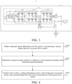
- FIG. 3 is another schematic diagram of a power drive circuit according to an exemplary embodiment.
- the power drive circuit 104 further includes: a first capacitor 206.
- the first capacitor 206 is connected in parallel between the second end and the third end of the voltage adjustment circuit 203.
- the first capacitor 206 is configured to stabilize the output voltage of the voltage adjustment circuit 203, so that the power drive circuit 104 is safer and more effective.
- the power drive circuit 104 further includes: a pre-charging circuit 208 and a second capacitor 207.
- the first end of the voltage adjustment circuit 203 is connected to the first end of the battery pack 201 through the pre-charging circuit 208, and the second capacitor 207 is connected in parallel between the first end of the voltage adjustment circuit 203 and the second end of the battery pack 201.
- the first end of the battery pack 201 represents a positive electrode
- the second end of the battery pack 201 represents a negative electrode.
- a first end of the pre-charging circuit 208 is connected between the positive electrode of the battery pack 201 and the first switch 202, a second end of the pre-charging circuit 208 is connected to the first end of the voltage adjustment circuit 203, and the second capacitor 207 is connected in parallel between the second end of the pre-charging circuit 208 and the negative electrode of the battery pack 201.
- An operating status of the pre-charging circuit 208 is controlled by the control apparatus.
- the control apparatus controls the first switch 202 to be turned off, the control apparatus further controls the pre-charging circuit 208 to be started.
- the pre-charging circuit 208 is configured to pre-charge the second capacitor 207.
- the pre-charging circuit 208 includes a second switch 601, a third switch 602, and a current limiting resistor 603.
- a first end of the second switch 601 is configured as a first end of the pre-charging circuit 208
- a second end of the second switch 601 is configured as a second end of the pre-charging circuit 208
- a branch in which the third switch 602 is connected in series with the current limiting resistor 603 is connected in parallel to two ends of the second switch 601.
- the control apparatus is specifically configured to control on or off of the second switch 601 and the third switch 602 in the pre-charging circuit 208.
- the control apparatus may simultaneously control the second switch 601 to be turned off and the third switch 602 to be turned on.
- the battery pack 201 precharges the second capacitor 207 sequentially through the third switch 602 and the current limiting resistor 603.
- the control apparatus may be further configured to control the second switch 601 to be turned on and the third switch 602 to be turned off.
- the pre-charging circuit 208 stops pre-charging the second capacitor 207, and the entire pre-charging circuit 208 serves as a wire, so that the voltage adjustment circuit 203 is directly connected to the positive electrode of the battery pack 201.
- the power drive circuit 104 further includes a fuse 209.
- the fuse 209 is connected in series between the first end of the battery pack 201 and the first switch 202, and the first end of the voltage adjustment circuit 203 is connected to an end of the fuse 209 away from the first end of the battery pack 201.
- the first end of the battery pack 201 represents a positive electrode, that is, the fuse 209 is connected in series between the positive electrode of the battery pack 201 and the first switch 202. Therefore, the first end of the voltage adjustment circuit 203 is connected between the fuse 209 and the first switch 202, and the first end of the pre-charging circuit 208 is connected between the fuse 209 and the first switch 202. In addition, the fuse 209 is always in an operating state, to protect safety of the power drive circuit 104, so that the power drive circuit 104 can operate normally.
- an embodiment of the present disclosure provides a method for driving power.
- the method is for controlling the power drive system 10. It should be noted that, in the method, the first switch 202 may be controlled to be turned on or off according to a target traveling mode of the vehicle 1 at a next moment, and the operating statuses of the voltage adjustment circuit 203, the first bridge-arm conversion circuit 204, and the second bridge-arm conversion circuit 205 may be controlled.
- a traveling mode of the vehicle 1 includes, but is not limited to, a startup mode, a startup enhancement mode, a low-speed uniform traveling mode, a high-speed uniform traveling mode, an acceleration mode, an acceleration enhancement mode, a braking energy storage mode, and a parking electricity generation mode.
- the method may be applied to the control apparatus.
- FIG. 4 is a flowchart of a method for driving power according to an exemplary embodiment.
- the method for driving power includes the following steps.
- the first motor represents a driving motor
- the second motor represents an electric generator
- a target traveling mode of a vehicle at a next moment is determined according to the rotational speed information.
- the target traveling mode of the vehicle at the next moment may be determined according to gear information of the vehicle and the rotational speed information of the first motor, the second motor, and the engine.
- S403 A first switch, a voltage adjustment circuit, a first bridge-arm conversion circuit, and a second bridge-arm conversion circuit that are in the power drive system are controlled, to enter the target traveling mode.
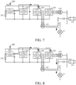
- FIG. 5 to FIG. 12 are schematic diagrams of operation processes of a power drive system for different traveling modes according to exemplary embodiments. The operation processes of the power drive system are described below with reference to FIG. 5 to FIG. 12 .
- the target traveling mode at the next moment is a startup mode.
- the first switch 202 is controlled to be turned on, the voltage adjustment circuit 203 is controlled not to operate, and the first bridge-arm conversion circuit 204 and the second bridge-arm conversion circuit 205 are controlled to perform direct current to alternating current conversion, to enter the startup mode.
- the engine 101 is in a closed state.
- the control apparatus controls the first switch 202 to be turned on, and the turned-on first switch 202 serves as a wire, so that the battery pack 201 skips the voltage adjustment circuit 203, and directly supplies electricity to the first bridge-arm conversion circuit 204 and the second bridge-arm conversion circuit 205, to enable the battery pack 201 to reach a maximum output power.
- the control apparatus controls the first bridge-arm conversion circuit 204 and the second bridge-arm conversion circuit 205 to perform direct current to alternating current conversion.
- the first bridge-arm conversion circuit 204 converts a direct current outputted by the voltage adjustment circuit 203 into a three-phase alternating current, to supply electricity to the first motor 102, so as to control the first motor 102 to operate.
- the second bridge-arm conversion circuit 205 converts the direct current outputted by the voltage adjustment circuit 203 into a three-phase alternating current, to supply electricity to the second motor 103, so as to control the second motor 103 to operate.
- the second motor 103 functions as an electric motor.
- the first motor 102 represents a driving motor
- the second motor 103 represents an electric generator.
- the first motor 102 is connected to the wheel 11 through mechanical coupling
- the second motor 103 is connected to the wheel 11 through mechanical coupling and a clutch. Therefore, the first motor 102 and the second motor 103 jointly drive the wheel 11 to rotate through the mechanical coupling and the clutch, to improve the dynamic performance of the vehicle at a startup stage.
- the target traveling mode at the next moment is a startup enhancement mode.
- the first switch 202 is controlled to be turned on, the voltage adjustment circuit 203 is controlled not to operate, the first bridge-arm conversion circuit 204 is controlled to perform direct current to alternating current conversion, and the second bridge-arm conversion circuit 205 is controlled to perform direct current to alternating current conversion or alternating current to direct current conversion, to enter the startup enhancement mode.
- the startup enhancement mode In comparison with the startup mode, in the startup enhancement mode, the engine 101 is in an operating state, to provide more power for the vehicle, and the startup enhancement mode is a startup mode with stronger dynamic performance.
- the control apparatus controls the first switch 202 to be turned on, and the turned-on first switch 202 serves as a wire, so that the battery pack 201 skips the voltage adjustment circuit 203, and directly supplies electricity to the first bridge-arm conversion circuit 204 and the second bridge-arm conversion circuit 205, to enable the battery pack 201 to reach a maximum output power.
- the control apparatus controls the first bridge-arm conversion circuit 204 to perform direct current to alternating current conversion.
- the first bridge-arm conversion circuit 204 converts a direct current outputted by the voltage adjustment circuit 203 into a three-phase alternating current, to supply electricity to the first motor 102, so as to control the first motor 102 to operate.
- the control apparatus controls the operating status of the second bridge-arm conversion circuit 205 as required, to avoid an excessively fast rotational speed or an excessively slow rotational speed of the engine 101.
- the second motor 103 and the engine 101 convert excess mechanical energy generated by the engine 101 into electric energy.
- the control apparatus controls the second bridge-arm conversion circuit 205 to perform alternating current to direct current conversion, and the second bridge-arm conversion circuit 205 converts a three-phase alternating current outputted by the second motor 103 into a direct current, to supply electricity to the first bridge-arm conversion circuit 204 and the second bridge-arm conversion circuit 205.
- the second motor 103 functions as an electric motor to assist the engine 101 in operating.
- the engine 101 is connected to the wheel 11 through mechanical coupling and a clutch
- the first motor 102 is connected to the wheel 11 through mechanical coupling
- the second motor 103 is connected to the wheel 11 through mechanical coupling and the clutch.
- the first bridge-arm conversion circuit 204 is controlled to perform direct current to alternating current conversion
- the second bridge-arm conversion circuit 205 is controlled to perform alternating current to direct current conversion.
- the engine 101 and the first motor 102 jointly drive the wheel 11 to rotate through the mechanical coupling and the clutch.
- the first bridge-arm conversion circuit 204 and the second bridge-arm conversion circuit 205 are controlled to perform direct current to alternating current conversion, and the engine 101, the first motor 102, and the second motor 103 jointly drive the wheel 11 to rotate through the mechanical coupling and the clutch. This greatly improves the dynamic performance of the vehicle at the startup stage.
- the control apparatus controls the first switch 202 to be turned off, and the battery pack 201 supplies electricity to the first bridge-arm conversion circuit 204 and the second bridge-arm conversion circuit 205 through the voltage adjustment circuit 203.
- the voltage adjustment circuit 203 serves as a boost circuit.
- the battery pack 201 supplies electricity to the first bridge-arm conversion circuit 204 and the second bridge-arm conversion circuit 205.
- the control apparatus controls the first bridge-arm conversion circuit 204 to perform direct current to alternating current conversion.
- the control apparatus controls the second bridge-arm conversion circuit 205 not to operate.
- the control apparatus controls the second bridge-arm conversion circuit 205 to perform direct current to alternating current conversion, and the second bridge-arm conversion circuit 205 converts the direct current output by the voltage adjustment circuit 203 into the three-phase alternating current, to supply electricity to the second motor 103, so as to control the second motor 103 to operate.
- the second motor 103 functions as an electric motor.
- the engine 101 is connected to the wheel 11 through mechanical coupling and a clutch
- the first motor 102 is connected to the wheel 11 through mechanical coupling
- the second motor 103 is connected to the wheel 11 through mechanical coupling and the clutch.
- the first bridge-arm conversion circuit 204 performs direct current to alternating current conversion, and the second bridge-arm conversion circuit 205 does not operate. In this case, only the first motor 102 drives the wheels 11 to rotate at a constant speed through the mechanical coupling.
- the first bridge-arm conversion circuit 204 and the second bridge-arm conversion circuit 205 perform direct current to alternating current conversion. In this case, the first motor 102 and the second motor 103 jointly drive the wheel 11 to rotate through the mechanical coupling and the clutch. This improves the dynamic performance of the vehicle at a low-speed and constant-speed stage.
- the voltage adjustment circuit 203 performs boosting, an output voltage of the voltage adjustment circuit 203 is increased, and the first motor 102 is only configured to maintain uniform traveling of the vehicle, so that a loss is reduced, and economy of the vehicle is improved.
- the target traveling mode at the next moment is a high-speed uniform traveling mode.
- the first switch 202 is controlled to be turned off
- the voltage adjustment circuit 203 is controlled to perform boosting
- the first bridge-arm conversion circuit 204 is controlled to perform direct current to alternating current conversion
- the second bridge-arm conversion circuit 205 is controlled to perform direct current to alternating current conversion or alternating current to direct current conversion, to enter the high-speed uniform traveling mode.
- the engine 101 In comparison with the low-speed uniform traveling mode, in the high-speed uniform traveling mode, the engine 101 is in an operating state, to provide more power for the vehicle.
- the high-speed uniform traveling mode is a uniform driving mode with stronger dynamic performance.
- the control apparatus controls the first switch 202 to be turned off, and the battery pack 201 supplies electricity to the first bridge-arm conversion circuit 204 and the second bridge-arm conversion circuit 205 through the voltage adjustment circuit 203.
- the voltage adjustment circuit 203 serves as a boost circuit.
- the battery pack 201 supplies electricity to the first bridge-arm conversion circuit 204 and the second bridge-arm conversion circuit 205.
- the control apparatus controls the first bridge-arm conversion circuit 204 to perform direct current to alternating current conversion.
- the first bridge-arm conversion circuit 204 converts a direct current outputted by the voltage adjustment circuit 203 into a three-phase alternating current, to supply electricity to the first motor 102, so as to control the first motor 102 to operate, so that uniform rotation of the wheel 11 is maintained.
- the control apparatus controls the operating status of the second bridge-arm conversion circuit 205 as required, to avoid an excessively fast rotational speed or an excessively slow rotational speed of the engine 101.
- the second motor 103 and the engine 101 convert excess mechanical energy generated by the engine 101 into electric energy.
- the control apparatus controls the second bridge-arm conversion circuit 205 to perform alternating current to direct current conversion, and the second bridge-arm conversion circuit 205 converts a three-phase alternating current outputted by the second motor 103 into a direct current, to supply electricity to the first bridge-arm conversion circuit 204 and the second bridge-arm conversion circuit 205.
- the second motor 103 functions as an electric motor to assist the engine 101 in operating.
- the engine 101 is connected to the wheel 11 through mechanical coupling and a clutch
- the first motor 102 is connected to the wheel 11 through mechanical coupling
- the second motor 103 is connected to the wheel 11 through mechanical coupling and the clutch.
- the first bridge-arm conversion circuit 204 is controlled to perform direct current to alternating current conversion
- the second bridge-arm conversion circuit 205 is controlled to perform alternating current to direct current conversion.
- the engine 101 and the first motor 102 jointly drive the wheel 11 to rotate through the mechanical coupling and the clutch.
- the first bridge-arm conversion circuit 204 and the second bridge-arm conversion circuit 205 are controlled to perform direct current to alternating current conversion
- the engine 101, the first motor 102, and the second motor 103 jointly drive the wheel 11 to rotate through the mechanical coupling and the clutch. This greatly improves the dynamic performance of the vehicle at a high-speed and constant-speed stage.
- the target traveling mode at the next moment is an acceleration mode.
- the first switch 202 is controlled to be turned on, the voltage adjustment circuit 203 is controlled not to operate, and the first bridge-arm conversion circuit 204 and the second bridge-arm conversion circuit 205 are controlled to perform direct current to alternating current conversion, to enter the acceleration mode.
- the engine 101 is in a closed state.
- control apparatus controls the voltage adjustment circuit 203 not to operate, so that a previously increased output voltage of the voltage adjustment circuit 203 is gradually reduced, and after the output voltage is reduced to a voltage of the battery pack 201, the control apparatus controls the first switch 202 to be turned on.
- the control apparatus controls the first switch 202 to be turned on, and the turned-on first switch 202 serves as a wire, so that the battery pack 201 skips the voltage adjustment circuit 203, and directly supplies electricity to the first bridge-arm conversion circuit 204 and the second bridge-arm conversion circuit 205, to enable the battery pack 201 to reach a maximum output power.
- the control apparatus controls the first bridge-arm conversion circuit 204 and the second bridge-arm conversion circuit 205 to perform direct current to alternating current conversion.
- the first bridge-arm conversion circuit 204 converts a direct current outputted by the voltage adjustment circuit 203 into a three-phase alternating current, to supply electricity to the first motor 102, so as to control the first motor 102 to operate.
- the second bridge-arm conversion circuit 205 converts the direct current outputted by the voltage adjustment circuit 203 into a three-phase alternating current, to supply electricity to the second motor 103, so as to control the second motor 103 to operate.
- the second motor 103 functions as an electric motor.
- the engine 101 is connected to the wheel 11 through mechanical coupling and a clutch
- the first motor 102 is connected to the wheel 11 through mechanical coupling
- the second motor 103 is connected to the wheel 11 through mechanical coupling and the clutch. Therefore, the first motor 102 and the second motor 103 jointly drive the wheel 11 to rotate through the mechanical coupling and the clutch, to improve the dynamic performance of the vehicle at an acceleration stage.
- the target traveling mode at the next moment is an acceleration enhancement mode.
- the first switch 202 is controlled to be turned on, the voltage adjustment circuit 203 is controlled not to operate, the first bridge-arm conversion circuit 204 is controlled to perform direct current to alternating current conversion, and the second bridge-arm conversion circuit 205 is controlled to perform direct current to alternating current conversion or alternating current to direct current conversion, to enter the acceleration enhancement mode.
- the engine 101 In comparison with the acceleration mode, in the acceleration enhancement mode, the engine 101 is in an operating state, to provide more power for the vehicle, and the acceleration enhancement mode is an acceleration mode with stronger dynamic performance.
- control apparatus controls the voltage adjustment circuit 203 not to operate, so that a previously increased output voltage of the voltage adjustment circuit 203 is gradually reduced, and after the output voltage is reduced to a voltage of the battery pack 201, the control apparatus controls the first switch 202 to be turned on.
- the control apparatus controls the first switch 202 to be turned on, and the turned-on first switch 202 serves as a wire, so that the battery pack 201 skips the voltage adjustment circuit 203, and directly supplies electricity to the first bridge-arm conversion circuit 204 and the second bridge-arm conversion circuit 205, to enable the battery pack 201 to reach a maximum output power.
- the control apparatus controls the first bridge-arm conversion circuit 204 to perform direct current to alternating current conversion.
- the first bridge-arm conversion circuit 204 converts a direct current outputted by the voltage adjustment circuit 203 into a three-phase alternating current, to supply electricity to the first motor 102, so as to control the first motor 102 to operate.
- the control apparatus controls the operating status of the second bridge-arm conversion circuit 205 as required, to avoid an excessively fast rotational speed or an excessively slow rotational speed of the engine 101.
- the second motor 103 and the engine 101 convert excess mechanical energy generated by the engine 101 into electric energy.
- the control apparatus controls the second bridge-arm conversion circuit 205 to perform alternating current to direct current conversion, and the second bridge-arm conversion circuit 205 converts a three-phase alternating current outputted by the second motor 103 into a direct current, to supply electricity to the first bridge-arm conversion circuit 204 and the second bridge-arm conversion circuit 205.
- the second motor 103 functions as an electric motor to assist the engine 101 in operating.
- the engine 101 is connected to the wheel 11 through mechanical coupling and a clutch
- the first motor 102 is connected to the wheel 11 through mechanical coupling
- the second motor 103 is connected to the wheel 11 through mechanical coupling and the clutch.
- the first bridge-arm conversion circuit 204 is controlled to perform direct current to alternating current conversion
- the second bridge-arm conversion circuit 205 is controlled to perform alternating current to direct current conversion.
- the engine 101 and the first motor 102 jointly drive the wheel 11 to rotate through the mechanical coupling and the clutch.
- the first bridge-arm conversion circuit 204 and the second bridge-arm conversion circuit 205 are controlled to perform direct current to alternating current conversion
- the engine 101, the first motor 102, and the second motor 103 jointly drive the wheel 11 to rotate through the mechanical coupling and the clutch, to implement an acceleration function of the vehicle. This greatly improves the dynamic performance of the vehicle at an acceleration stage.
- the target traveling mode at the next moment is a braking energy storage mode.
- the first switch 202 is controlled to be turned off
- the voltage adjustment circuit 203 is controlled to perform bucking
- the first bridge-arm conversion circuit 204 is controlled to perform alternating current to direct current conversion
- the second bridge-arm conversion circuit 205 is controlled not to operate or perform alternating current to direct current conversion, to enter the braking energy storage mode.
- the control apparatus controls the first switch 202 to be turned off, and the control apparatus controls the voltage adjustment circuit 203 to perform bucking, so that an output voltage of the first bridge-arm conversion circuit 204 is reduced through the voltage adjustment circuit 203 and a reduced voltage is outputted to the battery pack 201.
- the control apparatus controls the first bridge-arm conversion circuit 204 to perform alternating current to direct current conversion, and controls the second bridge-arm conversion circuit 205 not to operate.
- the first motor 102 functions as an electric generator, the first motor 102 converts excess mechanical energy generated by the engine 101 into electric energy, and the first bridge-arm conversion circuit 204 converts a three-phase alternating current outputted by the first motor 102 into a direct current, to recycle the electric energy to the battery pack 201.
- the control apparatus controls the first switch 202 to be turned off, and the control apparatus controls the voltage adjustment circuit 203 to perform bucking, so that output voltages of the first bridge-arm conversion circuit 204 and the second bridge-arm conversion circuit 205 are reduced through the voltage adjustment circuit 203 and reduced voltages are outputted to the battery pack 201.
- the control apparatus controls the first bridge-arm conversion circuit 204 and the second bridge-arm conversion circuit 205 to perform alternating current to direct current conversion.
- the first motor 102 and the second motor 103 operate, and the first motor 102, the second motor 103, and the engine 101 convert excess mechanical energy generated by the engine 101 into electric energy, to recycle the electric energy to the battery pack 201.
- the engine 101 is connected to the wheel 11 through mechanical coupling and a clutch
- the first motor 102 is connected to the wheel 11 through mechanical coupling
- the second motor 103 is connected to the wheel 11 through mechanical coupling and the clutch.
- the voltage adjustment circuit 203 is controlled to serve as a buck circuit, so that a voltage between the second end and the third end of the voltage adjustment circuit 203 is reduced and then a reduced voltage is outputted to the battery pack 201, to charge the battery pack 201.
- the voltage adjustment circuit 203 stability of the output voltage for energy recycling is ensured, and the economy of the vehicle at a braking stage is improved.
- the target traveling mode at the next moment is a parking electricity generation mode.
- the first switch 202 is controlled to be turned on, the voltage adjustment circuit 203 is controlled not to operate, the first bridge-arm conversion circuit 204 is controlled not to operate, and the second bridge-arm conversion circuit 205 is controlled to perform alternating current to direct current conversion, to enter the parking electricity generation mode.
- the control apparatus controls the first switch 202 to be turned on.
- the turned-on first switch 202 serves as a wire, so that the second bridge-arm conversion circuit 205 skips the voltage adjustment circuit 203, and directly charges the battery pack 201 through the turned-on first switch 202.
- the engine 101 is in an operating state, so that the engine 101 drives the second motor 103 to generate electricity.
- the control apparatus controls the second bridge-arm conversion circuit 205 to perform alternating current to direct current conversion, the second motor 103 converts excess mechanical energy generated by the engine 101 into electric energy, and the control apparatus controls the second bridge-arm conversion circuit 205 to convert a three-phase alternating current outputted by the second motor 103 into a direct current, to recycle the electric energy to the battery pack 201. Therefore, the first switch 202 is controlled to be turned on, the voltage adjustment circuit 203 is skipped, and the battery pack 201 is directly charged, thereby improving a charging power and charging efficiency, shortening a charging time, and improving the economy and convenience of the vehicle at a stop electricity generation stage.
- the first switch 202, the voltage adjustment circuit 203, the first bridge-arm conversion circuit 204, and the second bridge-arm conversion circuit 205 are controlled.
- the voltage adjustment circuit 203 may be skipped to implement a large power output of the battery pack 201, thereby releasing full performance of the vehicle.
- a bus voltage can be increased, energy consumption and losses can be reduced, and the economy of the vehicle can be ensured.
- the charging power and the charging efficiency can be improved, and the economy and the convenience of the vehicle can be improved.
- the target traveling mode of the vehicle at the next moment may be determined according to a working condition of the vehicle, and the battery pack is controlled, according to the target traveling mode at the next moment, to directly supply electricity to the bridge-arm conversion circuit or supply electricity to the bridge-arm conversion circuit after the voltage adjustment circuit performs boosting, to implement switching between enhancing the dynamic performance and enhancing the economy of the vehicle.
- the voltage adjustment circuit used in the present disclosure adopts a two-phase interleaved and parallel structure, so that an output power of the voltage adjustment circuit can reach a power that cannot be reached by an existing boost circuit, and interference is smaller.
- energy of the engine can be recycled, thereby improving the economy of the vehicle.
- the battery pack can be directly charged, which improves the charging power and efficiency, shortens the charging time, and improves the economy and the convenience of the vehicle.
- dynamic performance of a vehicle can be improved at a startup stage and an acceleration stage of the new energy vehicle, economy is implemented at a constant speed stage, and charging convenience is improved at a stop electricity generation stage, so that the new energy vehicle considers the dynamic performance, the economy, and the convenience.
Landscapes
- Engineering & Computer Science (AREA)
- Power Engineering (AREA)
- Transportation (AREA)
- Mechanical Engineering (AREA)
- Life Sciences & Earth Sciences (AREA)
- Sustainable Development (AREA)
- Sustainable Energy (AREA)
- Automation & Control Theory (AREA)
- Electric Propulsion And Braking For Vehicles (AREA)
Abstract
Description
- The present disclosure claims priority to and benefits of
Chinese Patent Application No. 202210837589.5, entitled "POWER DRIVE CIRCUIT, SYSTEM AND METHOD, AND VEHICLE" filed on July 15, 2022 - The present disclosure relates to the field of vehicle technologies, and specifically, to a power drive circuit, system and method, and a vehicle.
- An output power of a boost circuit of a new energy vehicle is usually less than a maximum output power of a battery pack. Due to a limitation of the output power of the boost circuit, the battery pack of the new energy vehicle cannot perform output at the maximum output power. As a result, dynamic performance of the new energy vehicle cannot be fully released. In most existing new energy vehicles, a small electricity supply apparatus or an energy storage device is newly added in the vehicle to improve the dynamic performance of the vehicle, for example, a supercapacitor is added. However, in this way, manufacturing costs and a volume of the vehicle are undoubtedly increased.
- An objective of the present disclosure is to provide a power drive circuit, system and method, and a vehicle, to resolve the foregoing technical problem.
- To achieve the objective, according to a first aspect, the present disclosure provides a power drive circuit, including: a battery pack, a first switch, a voltage adjustment circuit, a first bridge-arm conversion circuit, and a second bridge-arm conversion circuit. A first end of the voltage adjustment circuit is connected to a first end of the battery pack, and a second end of the voltage adjustment circuit is connected to a second end of the battery pack. The first switch is respectively connected to the first end of the battery pack and a third end of the voltage adjustment circuit. Both the first bridge-arm conversion circuit and the second bridge-arm conversion circuit are connected in parallel between the second end and the third end of the voltage adjustment circuit, the first bridge-arm conversion circuit is configured to connect to a first motor of a vehicle, and the second bridge-arm conversion circuit is configured to connect to a second motor of the vehicle.
- Optionally, the first bridge-arm conversion circuit includes a first switching transistor, a second switching transistor, a third switching transistor, a fourth switching transistor, a fifth switching transistor, and a sixth switching transistor. An input end of the first switching transistor is connected to the third end of the voltage adjustment circuit, an output end of the first switching transistor is connected to an input end of the second switching transistor, an output end of the second switching transistor is connected to the second end of the voltage adjustment circuit, an input end of the third switching transistor is connected to the input end of the first switching transistor, an output end of the third switching transistor is connected to an input end of the fourth switching transistor, an output end of the fourth switching transistor is connected to the output end of the second switching transistor, an input end of the fifth switching transistor is connected to the input end of the first switching transistor, an output end of the fifth switching transistor is connected to an input end of the sixth switching transistor, and an output end of the sixth switching transistor is connected to the output end of the second switching transistor. A first electricity supply end of the first motor is connected to the output end of the first switching transistor, a second electricity supply end of the first motor is connected to the output end of the third switching transistor, and a third electricity supply end of the first motor is connected to the output end of the fifth switching transistor.
- Optionally, the second bridge-arm conversion circuit includes a seventh switching transistor, an eighth switching transistor, a ninth switching transistor, a tenth switching transistor, an eleventh switching transistor, and a twelfth switching transistor. An input end of the seventh switching transistor is connected to the third end of the voltage adjustment circuit, an output end of the seventh switching transistor is connected to an input end of the eighth switching transistor, an output end of the eighth switching transistor is connected to the second end of the voltage adjustment circuit, an input end of the ninth switching transistor is connected to the input end of the seventh switching transistor, an output end of the ninth switching transistor is connected to an input end of the tenth switching transistor, an output end of the tenth switching transistor is connected to the output end of the eighth switching transistor, an input end of the eleventh switching transistor is connected to the input end of the seventh switching transistor, an output end of the eleventh switching transistor is connected to an input end of the twelfth switching transistor, and an output end of the twelfth switching transistor is connected to the output end of the eighth switching transistor. A first electricity supply end of the second motor is connected to the output end of the seventh switching transistor, a second electricity supply end of the second motor is connected to the output end of the ninth switching transistor, and a third electricity supply end of the second motor is connected to the output end of the eleventh switching transistor.
- Optionally, the voltage adjustment circuit includes a thirteenth switching transistor, a fourteenth switching transistor, a fifteenth switching transistor, a sixteenth switching transistor, a first inductor, and a second inductor. An input end of the thirteenth switching transistor and/or an input end of the fifteenth switching transistor are/is configured as the third end of the voltage adjustment circuit, an output end of the thirteenth switching transistor is connected to an input end of the fourteenth switching transistor, an output end of the fourteenth switching transistor and/or an output end of the sixteenth switching transistor are/is configured as the second end of the voltage adjustment circuit, the input end of the fifteenth switching transistor is connected to the input end of the thirteenth switching transistor, an output end of the fifteenth switching transistor is connected to an input end of the sixteenth switching transistor, and the output end of the sixteenth switching transistor is connected to the output end of the fourteenth switching transistor. A first end of the first inductor is connected to the output end of the thirteenth switching transistor, a second end of the first inductor and/or a second end of the second inductor are/is configured as the first end of the voltage adjustment circuit, a first end of the second inductor is connected to the output end of the fifteenth switching transistor, and the second end of the second inductor is connected to the second end of the first inductor.
- Optionally, the power drive circuit further includes a first capacitor. The first capacitor is connected in parallel between the second end and the third end of the voltage adjustment circuit.
- Optionally, the power drive circuit further includes a pre-charging circuit and a second capacitor. The first end of the voltage adjustment circuit is connected to the first end of the battery pack through the pre-charging circuit, and the second capacitor is connected in parallel between the first end of the voltage adjustment circuit and the second end of the battery pack.
- Optionally, the pre-charging circuit includes a second switch, a third switch, and a current limiting resistor. A first end of the second switch is configured as a first end of the pre-charging circuit, a second end of the second switch is configured as a second end of the pre-charging circuit, and a branch in which the third switch is connected in series with the current limiting resistor is connected in parallel to two ends of the second switch.
- Optionally, the power drive circuit further includes a fuse. The fuse is connected in series between the first end of the battery pack and the first switch, and the first end of the voltage adjustment circuit is connected to an end of the fuse away from the first end of the battery pack.
- According to a second aspect, the present disclosure provides a power drive system, including: an engine, a first motor, a second motor, and the power drive circuit according to the first aspect. The first motor is respectively connected to the second motor and the engine, and the second motor is connected to the engine.
- According to a third aspect, the present disclosure provides a method for driving power, for controlling the power drive system according to the second aspect. The method includes:
- Rotational speed information of the first motor, the second motor, and the engine that are in the power drive system is obtained;
- a target traveling mode of a vehicle at a next moment is determined according to the rotational speed information; and
- the first switch, the voltage adjustment circuit, the first bridge-arm conversion circuit, and the second bridge-arm conversion circuit that are in the power drive system are controlled, to enter the target traveling mode.
- Optionally, the target traveling mode is a startup mode or a startup enhancement mode, and that the first switch, the voltage adjustment circuit, the first bridge-arm conversion circuit, and the second bridge-arm conversion circuit that are in the power drive system are controlled, to enter the target traveling mode includes:
- The first switch is controlled to be turned on, the voltage adjustment circuit is controlled not to operate, and the first bridge-arm conversion circuit and the second bridge-arm conversion circuit are controlled to perform direct current to alternating current conversion, to enter the startup mode; or
the first switch is controlled to be turned on, the voltage adjustment circuit is controlled not to operate, the first bridge-arm conversion circuit is controlled to perform direct current to alternating current conversion, and the second bridge-arm conversion circuit is controlled to perform direct current to alternating current conversion or alternating current to direct current conversion, to enter the startup enhancement mode. - Optionally, the target traveling mode is a low-speed uniform traveling mode, a high-speed uniform traveling mode, an acceleration mode, or an acceleration enhancement mode, and that the first switch, the voltage adjustment circuit, the first bridge-arm conversion circuit, and the second bridge-arm conversion circuit that are in the power drive system are controlled, to enter the target traveling mode includes:
- The first switch is controlled to be turned off, the voltage adjustment circuit is controlled to perform boosting, the first bridge-arm conversion circuit is controlled to perform direct current to alternating current conversion, and the second bridge-arm conversion circuit is controlled not to operate or perform direct current to alternating current conversion, to enter the low-speed uniform traveling mode; or
- the first switch is controlled to be turned off, the voltage adjustment circuit is controlled to perform boosting, the first bridge-arm conversion circuit is controlled to perform direct current to alternating current conversion, and the second bridge-arm conversion circuit is controlled to perform direct current to alternating current conversion or alternating current to direct current conversion, to enter the high-speed uniform traveling mode; or
- the first switch is controlled to be turned on, the voltage adjustment circuit is controlled not to operate, and the first bridge-arm conversion circuit and the second bridge-arm conversion circuit are controlled to perform direct current to alternating current conversion, to enter the acceleration mode; or
- the first switch is controlled to be turned on, the voltage adjustment circuit is controlled not to operate, the first bridge-arm conversion circuit is controlled to perform direct current to alternating current conversion, and the second bridge-arm conversion circuit is controlled to perform direct current to alternating current conversion or alternating current to direct current conversion, to enter the acceleration enhancement mode.
- Optionally, when the target traveling mode is a braking energy storage mode or a parking electricity generation mode, the method for driving power includes:
- The first switch is controlled to be turned off, the voltage adjustment circuit is controlled to perform bucking, the first bridge-arm conversion circuit is controlled to perform alternating current to direct current conversion, and the second bridge-arm conversion circuit is controlled not to operate or perform alternating current to direct current conversion, to enter the braking energy storage mode; or
- the first switch is controlled to be turned on, the voltage adjustment circuit is controlled not to operate, the first bridge-arm conversion circuit is controlled not to operate, and the second bridge-arm conversion circuit is controlled to perform alternating current to direct current conversion, to enter the parking electricity generation mode.
- According to a fourth aspect, the present disclosure provides a vehicle, including:
- a wheel; and
- the power drive system according to the second aspect. The engine, the first motor, and the second motor that are in the power drive system are all connected to the wheel.
- Optionally, the vehicle further includes a control apparatus, connected to the first switch, the voltage adjustment circuit, the first bridge-arm conversion circuit, and the second bridge-arm conversion circuit that are in the power drive system. The control apparatus is configured to control the first switch, the voltage adjustment circuit, the first bridge-arm conversion circuit, and the second bridge-arm conversion circuit.
- According to the foregoing technical solutions, the first switch is arranged, and when the first switch is turned on, the battery pack can skip the voltage adjustment circuit and directly supply electricity to the first bridge-arm conversion circuit and the second bridge-arm conversion circuit, so that a large power output of the battery pack can be implemented, thereby improving dynamic performance of the vehicle. When the first switch is turned off, a voltage of the battery pack can be increased through the voltage adjustment circuit, thereby ensuring that the motors operate in a high-efficiency area and reducing energy consumption and losses.
- Other features and advantages of the present disclosure will be described in detail in the following detailed description part.
- The accompanying drawings are provided to further understand the present disclosure, and they constitute a part of the specification. The accompanying drawings, along with the specific implementations, are used to explain the present disclosure, and pose no limitation on the present disclosure. In the accompanying drawings:
-
FIG. 1 is a schematic diagram of a vehicle according to an exemplary embodiment. -
FIG. 2 is a schematic diagram of a power drive circuit according to an exemplary embodiment. -
FIG. 3 is another schematic diagram of a power drive circuit according to an exemplary embodiment. -
FIG. 4 is a flowchart of a method for driving power according to an exemplary embodiment. -
FIG. 5 to FIG. 12 are schematic diagrams of operation processes of a power drive system for different traveling modes according to exemplary embodiments. - In the drawings:
1-vehicle; 10-power drive system; 11-wheel; 101-engine; 102-first motor; 103-second motor; 104-power drive circuit; 201-battery pack; 202-first switch; 203-voltage adjustment circuit; 204-first bridge-arm conversion circuit; 205-second bridge-arm conversion circuit; 206-first capacitor; 207-second capacitor; 208-pre-charging circuit; 209-fuse; 301-thirteenth switching transistor; 302-fourteenth switching transistor; 303-fifteenth switching transistor; 304-sixteenth switching transistor; 305-first inductor; 306-second inductor; 401-first switching transistor; 402-second switching transistor; 403-third switching transistor; 404-fourth switching transistor; 405-fifth switching transistor; 406-sixth switching transistor; 501-seventh switching transistor; 502-eighth switching transistor; 503-ninth switching transistor; 504-tenth switching transistor; 505-eleventh switching transistor; 506-twelfth switching transistor; 601-second switch; 602-third switch; and 603-current limiting resistor. - Specific implementations of the present disclosure are described in detail below with reference to the accompanying drawings. It should be understood that the specific implementations described herein are merely used to describe and explain the present disclosure, but are not intended to limit the present disclosure.
- It should be noted that all actions of obtaining signals, information, or data in the present disclosure are performed under the premise of complying with corresponding data protection regulations and policies of a country and authorization granted by an owner of a corresponding apparatus.
- New energy vehicles have three optimization directions: dynamic performance, economy, and convenience. Through research, the inventor discovers that the dynamic performance can be improved by increasing an output power, the economy can be improved by increasing a bus voltage, and the convenience can be improved by shortening charging time. For the dynamic performance, an output power of a boost circuit of an existing new energy vehicle cannot reach a maximum output power of a battery pack. Due to a limitation of the output power of the boost circuit, the battery pack of the new energy vehicle cannot perform output at the maximum output power. As a result, the dynamic performance of the new energy vehicle cannot be fully released.
- To resolve the problem, an embodiment of the present disclosure provides a power drive circuit. The power drive circuit can improve dynamic performance, economy, and convenience of a vehicle. To improve the dynamic performance, a battery pack skips a voltage adjustment circuit, frees from a limitation of a power component in the voltage adjustment circuit, and directly supplies electricity to a first motor and a second motor, to improve an output power and an output current, and increase a torque of the first motor. This improves the dynamic performance. To improve the economy, a voltage of the battery pack is increased to a bus voltage (which refers to an output voltage between a second end and a third end of the voltage adjustment circuit in the present disclosure) through the voltage adjustment circuit, thereby ensuring that the motors operate in a high-efficiency area and reducing energy consumption and losses. In addition, electric energy is recycled to the battery pack during braking, thereby improving the economy. To improve the convenience, the battery pack is directly charged, to shorten charging time. This improves the convenience.
- First,
FIG. 1 is a schematic diagram of a vehicle according to an exemplary embodiment. Referring toFIG. 1 , thevehicle 1 includes: apower drive system 10 and awheel 11. Thepower drive system 10 is configured to drive thewheel 11 to rotate. - Optionally, as shown in
FIG. 1 , thepower drive system 10 includes: anengine 101, afirst motor 102, asecond motor 103, and apower drive circuit 104. Theengine 101, thefirst motor 102, and thesecond motor 103 that are in thepower drive system 10 are all connected to thewheel 11. Thefirst motor 102 is respectively connected to thesecond motor 103 and theengine 101, and thesecond motor 103 is connected to theengine 101. - The
first motor 102 represents a driving motor, and thesecond motor 103 represents an electric generator. Thefirst motor 102 and thesecond motor 103 may be connected through mechanical coupling, thefirst motor 102 and theengine 101 may be connected through mechanical coupling, and thesecond motor 103 and theengine 101 may be connected through mechanical coupling. - For example, the
engine 101 is connected to thewheel 11 through mechanical coupling and a clutch, thefirst motor 102 is connected to thewheel 11 through mechanical coupling, and thesecond motor 103 is connected to thewheel 11 through mechanical coupling and the clutch. Thefirst motor 102 and thesecond motor 103 are connected through the mechanical coupling and the clutch, thefirst motor 102 and theengine 101 are also connected through the mechanical coupling and the clutch, and thesecond motor 103 and theengine 101 are connected through the mechanical coupling. - Certainly, the present disclosure also does not exclude that the
first motor 102 and thesecond motor 103 are connected in another connection manner, thefirst motor 102 and theengine 101 are connected in another connection manner, and thesecond motor 103 and theengine 101 are connected in another connection manner. The connection manners that enable thefirst motor 102, thesecond motor 103, and theengine 101 to drive thewheel 11 to rotate should be included in the present disclosure. - Optionally, as shown in
FIG. 1 , thepower drive circuit 104 includes: abattery pack 201, afirst switch 202, avoltage adjustment circuit 203, a first bridge-arm conversion circuit 204, and a second bridge-arm conversion circuit 205. A first end of thevoltage adjustment circuit 203 is connected to a first end of thebattery pack 201, and a second end of thevoltage adjustment circuit 203 is connected to a second end of thebattery pack 201; thefirst switch 202 is respectively connected to the first end of thebattery pack 201 and a third end of thevoltage adjustment circuit 203. Both the first bridge-arm conversion circuit 204 and the second bridge-arm conversion circuit 205 are connected in parallel between the second end and the third end of thevoltage adjustment circuit 203, the first bridge-arm conversion circuit 204 is configured to connect to thefirst motor 102, and the second bridge-arm conversion circuit 205 is configured to connect to thesecond motor 103. - Optionally, the first end of the
battery pack 201 represents a positive electrode of thebattery pack 201, the second end of thebattery pack 201 represents a negative electrode of thebattery pack 201, thefirst motor 102 represents a driving motor, and thesecond motor 103 represents an electric generator. - Optionally, the
vehicle 1 further includes: a control apparatus (not shown in the figure). The control apparatus is connected to thefirst switch 202, thevoltage adjustment circuit 203, the first bridge-arm conversion circuit 204, and the second bridge-arm conversion circuit 205 that are in thepower drive system 10. The control apparatus is configured to control thefirst switch 202, thevoltage adjustment circuit 203, the first bridge-arm conversion circuit 204, and the second bridge-arm conversion circuit 205. - In the
power drive system 10, thefirst switch 202, thevoltage adjustment circuit 203, the first bridge-arm conversion circuit 204, and the second bridge-arm conversion circuit 205 are connected to the control apparatus. The control apparatus is configured to determine a target traveling mode of thevehicle 1 at a next moment, control thefirst switch 202 to be turned on or off, and control operating statuses of thevoltage adjustment circuit 203, the first bridge-arm conversion circuit 204, and the second bridge-arm conversion circuit 205 according to the target traveling mode. For example, the control apparatus may control thevoltage adjustment circuit 203 to perform boosting (boost a voltage provided by the battery pack) or bucking (buck a voltage provided by the first bridge-arm conversion circuit and/or the second bridge-arm conversion circuit). For another example, the control apparatus may further control the first bridge-arm conversion circuit 204 and the second bridge-arm conversion circuit 205 to operate or not to operate. Specifically, the control apparatus may control the first bridge-arm conversion circuit 204 and the second bridge-arm conversion circuit 205 to perform a forward operation (direct current to alternating current conversion) or a backward operation (alternating current to direct current conversion). - Specifically, if the
first switch 202 is turned on, in this case, thebattery pack 201 skips thevoltage adjustment circuit 203 and directly supplies electricity to the first bridge-arm conversion circuit 204 and the second bridge-arm conversion circuit 205 through the turned-onfirst switch 202, to resolve a problem that dynamic performance of the vehicle is limited because an output power of thevoltage adjustment circuit 203 is less than an output power of thebattery pack 201, and increase the output power and a torque of the motor. The output power may be for measuring a highest speed of the vehicle, and the output power is positively correlated with the highest speed of the vehicle. The torque of the motor may be for measuring an acceleration capability of the vehicle, and the torque of the motor is positively correlated with acceleration performance of the vehicle. After the output power and the torque of the motor are increased, the dynamic performance of the vehicle is significantly improved. - Specifically, if the
first switch 202 is turned off, in this case, thevoltage adjustment circuit 203 may serve as a boost circuit or a buck circuit. When thevoltage adjustment circuit 203 serves as the boost circuit, thevoltage adjustment circuit 203 increases a voltage of thebattery pack 201 to a bus voltage, and thebattery pack 201 supplies electricity to the first bridge-arm conversion circuit 204 and the second bridge-arm conversion circuit 205. Increase of an output voltage of thevoltage adjustment circuit 203 can ensure that thefirst motor 102 and thesecond motor 103 operate in a high-efficiency area, and reduce energy consumption and losses of thefirst motor 102 and thesecond motor 103. This improves economy of the vehicle. When thevoltage adjustment circuit 203 serves as the buck circuit, after a bus voltage is reduced, a reduced bus voltage is outputted to thebattery pack 201, thebattery pack 201 is charged, stability of an output voltage is ensured, and energy recycling is implemented, thereby improving economy of the vehicle. - In an actual application scenario, the control apparatus may control on/off of the
first switch 202, to control whether thebattery pack 201 supplies electricity to the first bridge-arm conversion circuit 204 and the second bridge-arm conversion circuit 205 through thevoltage adjustment circuit 203, so that the dynamic performance and the economy of the vehicle can be improved, and conversion between the dynamic performance and the economy can also be implemented. -
FIG. 2 is a schematic diagram of a power drive circuit according to an exemplary embodiment. Referring toFIG. 2 , the first bridge-arm conversion circuit 204 includes: afirst switching transistor 401, asecond switching transistor 402, athird switching transistor 403, afourth switching transistor 404, afifth switching transistor 405, and asixth switching transistor 406. An input end of thefirst switching transistor 401 is connected to the third end of thevoltage adjustment circuit 203, an output end of thefirst switching transistor 401 is connected to an input end of thesecond switching transistor 402, an output end of thesecond switching transistor 402 is connected to the second end of thevoltage adjustment circuit 203, an input end of thethird switching transistor 403 is connected to the input end of thefirst switching transistor 401, an output end of thethird switching transistor 403 is connected to an input end of thefourth switching transistor 404, an output end of thefourth switching transistor 404 is connected to the output end of thesecond switching transistor 402, an input end of thefifth switching transistor 405 is connected to the input end of thefirst switching transistor 401, an output end of thefifth switching transistor 405 is connected to an input end of thesixth switching transistor 406, and an output end of thesixth switching transistor 406 is connected to the output end of thesecond switching transistor 402. A first electricity supply end of thefirst motor 102 is connected to the output end of thefirst switching transistor 401, a second electricity supply end of thefirst motor 102 is connected to the output end of thethird switching transistor 403, and a third electricity supply end of thefirst motor 102 is connected to the output end of thefifth switching transistor 405. - Control ends of the
first switching transistor 401, thesecond switching transistor 402, thethird switching transistor 403, thefourth switching transistor 404, thefifth switching transistor 405, and thesixth switching transistor 406 are configured to connect to the control apparatus. The control apparatus controls on/off of each of the switching transistors through the control end of each of the switching transistors, to control the operating status of the first bridge-arm conversion circuit 204. - Optionally, each of the switching transistors in the first bridge-
arm conversion circuit 204 may be an IGBT or an MOS transistor. If the switching transistor is the IGBT, the control end of each of the switching transistors is a gate, an input end is a collector, and an output end is an emitter. The IGBT is used as an example. The control apparatus sends a high level or a low level to the gate of each of the switching transistors to turn on or turn off each of the switching transistors correspondingly, so as to control the operating status of the first bridge-arm conversion circuit 204. - For example, the control apparatus sends the high level to the control ends of the
first switching transistor 401, thethird switching transistor 403, and thefifth switching transistor 405, to turn on thefirst switching transistor 401, thethird switching transistor 403, and thefifth switching transistor 405, and sends the low level to the control ends of thesecond switching transistor 402, thefourth switching transistor 404, and thesixth switching transistor 406, to turn off thesecond switching transistor 402, thefourth switching transistor 404, and thesixth switching transistor 406, so as to enable the first bridge-arm conversion circuit 204 to operate. The control apparatus sends the low level to the control end of each of the switching transistors in the first bridge-arm conversion circuit 204, to turn off each of the switching transistors in the first bridge-arm conversion circuit 204, so as to enable the first bridge-arm conversion circuit 204 not to operate. - When the first bridge-
arm conversion circuit 204 operates and obtains a voltage provided by the second end and the third end of thevoltage adjustment circuit 203, the first bridge-arm conversion circuit 204 converts a direct current into a three-phase alternating current, and supplies electricity to thefirst motor 102 through the first electricity supply end, the second electricity supply end, and the third electricity supply end of thefirst motor 102. After obtaining the electricity, thefirst motor 102 drives thewheel 11 to rotate. When the first bridge-arm conversion circuit 204 operates and obtains a voltage provided by thefirst motor 102, the first bridge-arm conversion circuit 204 converts a three-phase alternating current into a direct current, to recycle electric energy to thebattery pack 201. - Optionally, as shown in
FIG. 2 , the second bridge-arm conversion circuit 205 includes: aseventh switching transistor 501, aneighth switching transistor 502, aninth switching transistor 503, atenth switching transistor 504, an eleventh switching transistor 505, and atwelfth switching transistor 506. An input end of theseventh switching transistor 501 is connected to the third end of thevoltage adjustment circuit 203, an output end of theseventh switching transistor 501 is connected to an input end of theeighth switching transistor 502, an output end of theeighth switching transistor 502 is connected to the second end of thevoltage adjustment circuit 203, an input end of theninth switching transistor 503 is connected to the input end of theseventh switching transistor 501, an output end of theninth switching transistor 503 is connected to an input end of thetenth switching transistor 504, an output end of thetenth switching transistor 504 is connected to the output end of theeighth switching transistor 502, an input end of the eleventh switching transistor 505 is connected to the input end of theseventh switching transistor 501, an output end of the eleventh switching transistor 505 is connected to an input end of thetwelfth switching transistor 506, and an output end of thetwelfth switching transistor 506 is connected to the output end of theeighth switching transistor 502. A first electricity supply end of thesecond motor 103 is connected to the output end of theseventh switching transistor 501, a second electricity supply end of thesecond motor 103 is connected to the output end of theninth switching transistor 503, and a third electricity supply end of thesecond motor 103 is connected to the output end of the eleventh switching transistor 505. - Control ends of the
seventh switching transistor 501, theeighth switching transistor 502, theninth switching transistor 503, thetenth switching transistor 504, the eleventh switching transistor 505, and thetwelfth switching transistor 506 are configured to connect to the control apparatus. The control apparatus controls on/off of each of the switching transistors through the control end of each of the switching transistors, to control the operating status of the second bridge-arm conversion circuit 205. - Optionally, each of the switching transistors in the second bridge-
arm conversion circuit 205 may be an IGBT or an MOS transistor. If the switching transistor is the IGBT, the control end of each of the switching transistors is a gate, an input end is a collector, and an output end is an emitter. The IGBT is used as an example. The control apparatus sends a high level or a low level to the gate of each of the switching transistors to turn on or turn off each of the switching transistors correspondingly, so as to control the operating status of the second bridge-arm conversion circuit 205. - For example, the control apparatus sends the high level to the control ends of the
seventh switching transistor 501, theninth switching transistor 503, and the eleventh switching transistor 505, to turn on theseventh switching transistor 501, theninth switching transistor 503, and the eleventh switching transistor 505, and sends the low level to the control ends of theeighth switching transistor 502, thetenth switching transistor 504, and thetwelfth switching transistor 506, to turn off theeighth switching transistor 502, thetenth switching transistor 504, and thetwelfth switching transistor 506, so as to enable the second bridge-arm conversion circuit 205 to operate. The control apparatus sends the low level to the control end of each of the switching transistors in the second bridge-arm conversion circuit 205, to turn off each of the switching transistors in the second bridge-arm conversion circuit 205, so as to enable the second bridge-arm conversion circuit 205 not to operate. - When the second bridge-
arm conversion circuit 205 operates and obtains a voltage provided by the second end and the third end of thevoltage adjustment circuit 203, the second bridge-arm conversion circuit 205 converts a direct current into a three-phase alternating current, and supplies electricity to thesecond motor 103 through the first electricity supply end, the second electricity supply end, and the third electricity supply end of thesecond motor 103. After obtaining the electricity, thesecond motor 103 drives thewheel 11 to rotate or assists theengine 101 in operating. When the second bridge-arm conversion circuit 205 operates and obtains a voltage provided by thesecond motor 103, the second bridge-arm conversion circuit 205 converts a three-phase alternating current into a direct current, to recycle electric energy to thebattery pack 201. - Optionally, as shown in
FIG. 2 , thevoltage adjustment circuit 203 includes: athirteenth switching transistor 301, afourteenth switching transistor 302, afifteenth switching transistor 303, asixteenth switching transistor 304, afirst inductor 305, and asecond inductor 306. An input end of thethirteenth switching transistor 301 and/or an input end of thefifteenth switching transistor 303 are/is configured as the third end of thevoltage adjustment circuit 203, an output end of thethirteenth switching transistor 301 is connected to an input end of thefourteenth switching transistor 302, an output end of thefourteenth switching transistor 302 and/or an output end of thesixteenth switching transistor 304 are/is configured as the second end of thevoltage adjustment circuit 203, the input end of thefifteenth switching transistor 303 is connected to the input end of thethirteenth switching transistor 301, an output end of thefifteenth switching transistor 303 is connected to an input end of thesixteenth switching transistor 304, and the output end of thesixteenth switching transistor 304 is connected to the output end of thefourteenth switching transistor 302. A first end of thefirst inductor 305 is connected to the output end of thethirteenth switching transistor 301, a second end of thefirst inductor 305 and/or a second end of thesecond inductor 306 are/is configured as the first end of thevoltage adjustment circuit 203, a first end of thesecond inductor 306 is connected to the output end of thefifteenth switching transistor 303, and the second end of thesecond inductor 306 is connected to the second end of thefirst inductor 305. - Because the input end of the
thirteenth switching transistor 301 is connected to the input end of thefifteenth switching transistor 303, both the input end of thethirteenth switching transistor 301 and the input end of thefifteenth switching transistor 303 may be configured as the third end of thevoltage adjustment circuit 203. Because the output end of thefourteenth switching transistor 302 is connected to the output end of thesixteenth switching transistor 304, both the output end of thefourteenth switching transistor 302 and the output end of thesixteenth switching transistor 304 may be configured as the third end of thevoltage adjustment circuit 203. - Control ends of the
thirteenth switching transistor 301, thefourteenth switching transistor 302, thefifteenth switching transistor 303, and thesixteenth switching transistor 304 are configured to connect to the control apparatus. The control apparatus controls on/off of each of the switching transistors through the control end of each of the switching transistors, to control the operating status of thevoltage adjustment circuit 203. - Optionally, each of the switching transistors in the
voltage adjustment circuit 203 may be an IGBT or an MOS transistor. If the switching transistor is the IGBT, the control end of each of the switching transistors is a gate, an input end is a collector, and an output end is an emitter. The IGBT is used as an example. The control apparatus sends a high level or a low level to the gate of each of the switching transistors to turn on or turn off each of the switching transistors correspondingly, so as to control the operating status of thevoltage adjustment circuit 203. - When operating, the
voltage adjustment circuit 203 may serve as a boost circuit or a buck circuit. For a specific function of serving as the boost circuit or the buck circuit, reference may be made to the foregoing descriptions. Details are not described herein again. - For example, the control apparatus sends the high level to the control ends of the
thirteenth switching transistor 301 and thesixteenth switching transistor 304, to turn on thethirteenth switching transistor 301 and thesixteenth switching transistor 304, and sends the low level to the control ends of thefourteenth switching transistor 302 and thesixteenth switching transistor 304, to turn off thefourteenth switching transistor 302 and thefifteenth switching transistor 303, so as to enable thevoltage adjustment circuit 203 to operate. The control apparatus sends the low level to the control end of each of the switching transistors in thevoltage adjustment circuit 203, to turn off each of the switching transistors in thevoltage adjustment circuit 203, so as to enable thevoltage adjustment circuit 203 not to operate. - In addition, a two-phase interleaved and parallel structure is used as the structure of the
voltage adjustment circuit 203. The two-phase interleaved and parallel structure may enable the output power of thevoltage adjustment circuit 203 to reach 40 kW and have a smaller ripple, while a boost circuit on the market has an output power less than 40 kW and has a larger ripple. - Therefore, the
voltage adjustment circuit 203 of the two-phase interleaved and parallel structure is used. When thevoltage adjustment circuit 203 is configured as the boost circuit, an output power of the boost circuit can be increased, and thebattery pack 201 performs output at a maximum output power, so that it is ensured that thefirst motor 102 and thesecond motor 103 operate in the high-efficiency area, and energy consumption and losses of thefirst motor 102 and thesecond motor 103 are reduced, thereby improving the economy of the vehicle. -
FIG. 3 is another schematic diagram of a power drive circuit according to an exemplary embodiment. Referring toFIG. 3 , thepower drive circuit 104 further includes: afirst capacitor 206. Thefirst capacitor 206 is connected in parallel between the second end and the third end of thevoltage adjustment circuit 203. Thefirst capacitor 206 is configured to stabilize the output voltage of thevoltage adjustment circuit 203, so that thepower drive circuit 104 is safer and more effective. - Optionally, as shown in
FIG. 3 , thepower drive circuit 104 further includes: apre-charging circuit 208 and asecond capacitor 207. The first end of thevoltage adjustment circuit 203 is connected to the first end of thebattery pack 201 through thepre-charging circuit 208, and thesecond capacitor 207 is connected in parallel between the first end of thevoltage adjustment circuit 203 and the second end of thebattery pack 201. The first end of thebattery pack 201 represents a positive electrode, and the second end of thebattery pack 201 represents a negative electrode. - A first end of the
pre-charging circuit 208 is connected between the positive electrode of thebattery pack 201 and thefirst switch 202, a second end of thepre-charging circuit 208 is connected to the first end of thevoltage adjustment circuit 203, and thesecond capacitor 207 is connected in parallel between the second end of thepre-charging circuit 208 and the negative electrode of thebattery pack 201. - An operating status of the
pre-charging circuit 208 is controlled by the control apparatus. When the control apparatus controls thefirst switch 202 to be turned off, the control apparatus further controls thepre-charging circuit 208 to be started. Thepre-charging circuit 208 is configured to pre-charge thesecond capacitor 207. - Optionally, as shown in
FIG. 3 , thepre-charging circuit 208 includes asecond switch 601, athird switch 602, and a current limitingresistor 603. A first end of thesecond switch 601 is configured as a first end of thepre-charging circuit 208, a second end of thesecond switch 601 is configured as a second end of thepre-charging circuit 208, and a branch in which thethird switch 602 is connected in series with the current limitingresistor 603 is connected in parallel to two ends of thesecond switch 601. - The control apparatus is specifically configured to control on or off of the
second switch 601 and thethird switch 602 in thepre-charging circuit 208. When controlling thefirst switch 202 to be turned off, the control apparatus may simultaneously control thesecond switch 601 to be turned off and thethird switch 602 to be turned on. In this case, thebattery pack 201 precharges thesecond capacitor 207 sequentially through thethird switch 602 and the current limitingresistor 603. The control apparatus may be further configured to control thesecond switch 601 to be turned on and thethird switch 602 to be turned off. In this case, thepre-charging circuit 208 stops pre-charging thesecond capacitor 207, and the entirepre-charging circuit 208 serves as a wire, so that thevoltage adjustment circuit 203 is directly connected to the positive electrode of thebattery pack 201. - It may be understood that, because the
second capacitor 207 has a specific capacity, if thebattery pack 201 is instantaneously connected to a loop, a relatively large instantaneous current is generated, and a line and thebattery pack 201 may be burnt out. The control apparatus controls thepre-charging circuit 208. When thepre-charging circuit 208 is started, the current limitingresistor 603 is connected to the loop to limit the instantaneous current. After thesecond capacitor 207 is fully charged, thepre-charging circuit 208 is controlled to stop operating, so that the entire circuit operates normally. Therefore, thepre-charging circuit 208 can protect thepower drive circuit 104. - Optionally, as shown in
FIG. 3 , thepower drive circuit 104 further includes afuse 209. Thefuse 209 is connected in series between the first end of thebattery pack 201 and thefirst switch 202, and the first end of thevoltage adjustment circuit 203 is connected to an end of thefuse 209 away from the first end of thebattery pack 201. - The first end of the
battery pack 201 represents a positive electrode, that is, thefuse 209 is connected in series between the positive electrode of thebattery pack 201 and thefirst switch 202. Therefore, the first end of thevoltage adjustment circuit 203 is connected between thefuse 209 and thefirst switch 202, and the first end of thepre-charging circuit 208 is connected between thefuse 209 and thefirst switch 202. In addition, thefuse 209 is always in an operating state, to protect safety of thepower drive circuit 104, so that thepower drive circuit 104 can operate normally. - Further, an embodiment of the present disclosure provides a method for driving power. The method is for controlling the
power drive system 10. It should be noted that, in the method, thefirst switch 202 may be controlled to be turned on or off according to a target traveling mode of thevehicle 1 at a next moment, and the operating statuses of thevoltage adjustment circuit 203, the first bridge-arm conversion circuit 204, and the second bridge-arm conversion circuit 205 may be controlled. - A traveling mode of the
vehicle 1 includes, but is not limited to, a startup mode, a startup enhancement mode, a low-speed uniform traveling mode, a high-speed uniform traveling mode, an acceleration mode, an acceleration enhancement mode, a braking energy storage mode, and a parking electricity generation mode. - In an exemplary embodiment, the method may be applied to the control apparatus.
-
FIG. 4 is a flowchart of a method for driving power according to an exemplary embodiment. Referring toFIG. 4 , the method for driving power includes the following steps. - S401: Rotational speed information of a first motor, a second motor, and an engine that are in a power drive system is obtained.
- The first motor represents a driving motor, and the second motor represents an electric generator.
- S402: A target traveling mode of a vehicle at a next moment is determined according to the rotational speed information.
- Specifically, the target traveling mode of the vehicle at the next moment may be determined according to gear information of the vehicle and the rotational speed information of the first motor, the second motor, and the engine.
- For example, assuming that a current gear of the vehicle is 4, an obtained rotational speed of the first motor is 12000 r/min, a rotational speed of the second motor is 7000 r/min, and a rotational speed of the engine is 3400 r/min, it is determined that the vehicle enters a high-speed uniform traveling mode at the next moment.
- S403: A first switch, a voltage adjustment circuit, a first bridge-arm conversion circuit, and a second bridge-arm conversion circuit that are in the power drive system are controlled, to enter the target traveling mode.
- After the target traveling mode of the vehicle at the next moment is determined, operating statuses of the first switch, the voltage adjustment circuit, the first bridge-arm conversion circuit, and the second bridge-arm conversion circuit that are in the power drive system are controlled, to enter the target traveling mode.
-
FIG. 5 to FIG. 12 are schematic diagrams of operation processes of a power drive system for different traveling modes according to exemplary embodiments. The operation processes of the power drive system are described below with reference toFIG. 5 to FIG. 12 . - Referring to
FIG. 5 , in an exemplary embodiment, the target traveling mode at the next moment is a startup mode. In step S403, thefirst switch 202 is controlled to be turned on, thevoltage adjustment circuit 203 is controlled not to operate, and the first bridge-arm conversion circuit 204 and the second bridge-arm conversion circuit 205 are controlled to perform direct current to alternating current conversion, to enter the startup mode. In this case, theengine 101 is in a closed state. - Specifically, the control apparatus controls the
first switch 202 to be turned on, and the turned-onfirst switch 202 serves as a wire, so that thebattery pack 201 skips thevoltage adjustment circuit 203, and directly supplies electricity to the first bridge-arm conversion circuit 204 and the second bridge-arm conversion circuit 205, to enable thebattery pack 201 to reach a maximum output power. The control apparatus controls the first bridge-arm conversion circuit 204 and the second bridge-arm conversion circuit 205 to perform direct current to alternating current conversion. The first bridge-arm conversion circuit 204 converts a direct current outputted by thevoltage adjustment circuit 203 into a three-phase alternating current, to supply electricity to thefirst motor 102, so as to control thefirst motor 102 to operate. The second bridge-arm conversion circuit 205 converts the direct current outputted by thevoltage adjustment circuit 203 into a three-phase alternating current, to supply electricity to thesecond motor 103, so as to control thesecond motor 103 to operate. In this case, thesecond motor 103 functions as an electric motor. Thefirst motor 102 represents a driving motor, and thesecond motor 103 represents an electric generator. - For example, the
first motor 102 is connected to thewheel 11 through mechanical coupling, and thesecond motor 103 is connected to thewheel 11 through mechanical coupling and a clutch. Therefore, thefirst motor 102 and thesecond motor 103 jointly drive thewheel 11 to rotate through the mechanical coupling and the clutch, to improve the dynamic performance of the vehicle at a startup stage. - Referring to
FIG. 6 , in an exemplary embodiment, the target traveling mode at the next moment is a startup enhancement mode. In step S403, thefirst switch 202 is controlled to be turned on, thevoltage adjustment circuit 203 is controlled not to operate, the first bridge-arm conversion circuit 204 is controlled to perform direct current to alternating current conversion, and the second bridge-arm conversion circuit 205 is controlled to perform direct current to alternating current conversion or alternating current to direct current conversion, to enter the startup enhancement mode. - In comparison with the startup mode, in the startup enhancement mode, the
engine 101 is in an operating state, to provide more power for the vehicle, and the startup enhancement mode is a startup mode with stronger dynamic performance. - Specifically, the control apparatus controls the
first switch 202 to be turned on, and the turned-onfirst switch 202 serves as a wire, so that thebattery pack 201 skips thevoltage adjustment circuit 203, and directly supplies electricity to the first bridge-arm conversion circuit 204 and the second bridge-arm conversion circuit 205, to enable thebattery pack 201 to reach a maximum output power. The control apparatus controls the first bridge-arm conversion circuit 204 to perform direct current to alternating current conversion. The first bridge-arm conversion circuit 204 converts a direct current outputted by thevoltage adjustment circuit 203 into a three-phase alternating current, to supply electricity to thefirst motor 102, so as to control thefirst motor 102 to operate. The control apparatus controls the operating status of the second bridge-arm conversion circuit 205 as required, to avoid an excessively fast rotational speed or an excessively slow rotational speed of theengine 101. - Specifically, when the rotational speed of the
engine 101 is excessively fast (for example, exceeds a first rotational speed threshold), thesecond motor 103 and theengine 101 convert excess mechanical energy generated by theengine 101 into electric energy. The control apparatus controls the second bridge-arm conversion circuit 205 to perform alternating current to direct current conversion, and the second bridge-arm conversion circuit 205 converts a three-phase alternating current outputted by thesecond motor 103 into a direct current, to supply electricity to the first bridge-arm conversion circuit 204 and the second bridge-arm conversion circuit 205. When the rotational speed of theengine 101 is excessively slow (for example, less than a second rotational speed threshold), thesecond motor 103 functions as an electric motor to assist theengine 101 in operating. - For example, the
engine 101 is connected to thewheel 11 through mechanical coupling and a clutch, thefirst motor 102 is connected to thewheel 11 through mechanical coupling, and thesecond motor 103 is connected to thewheel 11 through mechanical coupling and the clutch. - Therefore, when the rotational speed of the
engine 101 is excessively fast, the first bridge-arm conversion circuit 204 is controlled to perform direct current to alternating current conversion, and the second bridge-arm conversion circuit 205 is controlled to perform alternating current to direct current conversion. In this case, theengine 101 and thefirst motor 102 jointly drive thewheel 11 to rotate through the mechanical coupling and the clutch. When the rotational speed of theengine 101 is excessively slow, the first bridge-arm conversion circuit 204 and the second bridge-arm conversion circuit 205 are controlled to perform direct current to alternating current conversion, and theengine 101, thefirst motor 102, and thesecond motor 103 jointly drive thewheel 11 to rotate through the mechanical coupling and the clutch. This greatly improves the dynamic performance of the vehicle at the startup stage. - Referring to
FIG. 7 , in an exemplary embodiment, the target traveling mode at the next moment is a low-speed uniform traveling mode. In step S403, thefirst switch 202 is controlled to be turned off, thevoltage adjustment circuit 203 is controlled to perform boosting, the first bridge-arm conversion circuit 204 is controlled to perform direct current to alternating current conversion, and the second bridge-arm conversion circuit 205 is controlled not to operate or perform direct current to alternating current conversion, to enter the low-speed uniform traveling mode. In this case, theengine 101 is in a closed state. - Specifically, the control apparatus controls the
first switch 202 to be turned off, and thebattery pack 201 supplies electricity to the first bridge-arm conversion circuit 204 and the second bridge-arm conversion circuit 205 through thevoltage adjustment circuit 203. In this case, thevoltage adjustment circuit 203 serves as a boost circuit. After thevoltage adjustment circuit 203 performs boosting, thebattery pack 201 supplies electricity to the first bridge-arm conversion circuit 204 and the second bridge-arm conversion circuit 205. The control apparatus controls the first bridge-arm conversion circuit 204 to perform direct current to alternating current conversion. The first bridge-arm conversion circuit 204 converts a direct current outputted by thevoltage adjustment circuit 203 into a three-phase alternating current, to supply electricity to thefirst motor 102, so as to control thefirst motor 102 to operate, so that uniform rotation of thewheel 11 is maintained. The control apparatus controls the operating status of the second bridge-arm conversion circuit 205 as required. - Specifically, when the
first motor 102 provides sufficient power for the vehicle, the control apparatus controls the second bridge-arm conversion circuit 205 not to operate. When thefirst motor 102 provides insufficient power for the vehicle, the control apparatus controls the second bridge-arm conversion circuit 205 to perform direct current to alternating current conversion, and the second bridge-arm conversion circuit 205 converts the direct current output by thevoltage adjustment circuit 203 into the three-phase alternating current, to supply electricity to thesecond motor 103, so as to control thesecond motor 103 to operate. In this case, thesecond motor 103 functions as an electric motor. - For example, the
engine 101 is connected to thewheel 11 through mechanical coupling and a clutch, thefirst motor 102 is connected to thewheel 11 through mechanical coupling, and thesecond motor 103 is connected to thewheel 11 through mechanical coupling and the clutch. - Therefore, when the
first motor 102 provides the sufficient power for the vehicle, the first bridge-arm conversion circuit 204 performs direct current to alternating current conversion, and the second bridge-arm conversion circuit 205 does not operate. In this case, only thefirst motor 102 drives thewheels 11 to rotate at a constant speed through the mechanical coupling. When thefirst motor 102 provides the insufficient power for the vehicle, the first bridge-arm conversion circuit 204 and the second bridge-arm conversion circuit 205 perform direct current to alternating current conversion. In this case, thefirst motor 102 and thesecond motor 103 jointly drive thewheel 11 to rotate through the mechanical coupling and the clutch. This improves the dynamic performance of the vehicle at a low-speed and constant-speed stage. In addition, because thevoltage adjustment circuit 203 performs boosting, an output voltage of thevoltage adjustment circuit 203 is increased, and thefirst motor 102 is only configured to maintain uniform traveling of the vehicle, so that a loss is reduced, and economy of the vehicle is improved. - Referring to
FIG. 8 , in an exemplary embodiment, the target traveling mode at the next moment is a high-speed uniform traveling mode. In step S403, thefirst switch 202 is controlled to be turned off, thevoltage adjustment circuit 203 is controlled to perform boosting, the first bridge-arm conversion circuit 204 is controlled to perform direct current to alternating current conversion, and the second bridge-arm conversion circuit 205 is controlled to perform direct current to alternating current conversion or alternating current to direct current conversion, to enter the high-speed uniform traveling mode. - In comparison with the low-speed uniform traveling mode, in the high-speed uniform traveling mode, the
engine 101 is in an operating state, to provide more power for the vehicle. The high-speed uniform traveling mode is a uniform driving mode with stronger dynamic performance. - Specifically, the control apparatus controls the
first switch 202 to be turned off, and thebattery pack 201 supplies electricity to the first bridge-arm conversion circuit 204 and the second bridge-arm conversion circuit 205 through thevoltage adjustment circuit 203. In this case, thevoltage adjustment circuit 203 serves as a boost circuit. After thevoltage adjustment circuit 203 performs boosting, thebattery pack 201 supplies electricity to the first bridge-arm conversion circuit 204 and the second bridge-arm conversion circuit 205. The control apparatus controls the first bridge-arm conversion circuit 204 to perform direct current to alternating current conversion. The first bridge-arm conversion circuit 204 converts a direct current outputted by thevoltage adjustment circuit 203 into a three-phase alternating current, to supply electricity to thefirst motor 102, so as to control thefirst motor 102 to operate, so that uniform rotation of thewheel 11 is maintained. The control apparatus controls the operating status of the second bridge-arm conversion circuit 205 as required, to avoid an excessively fast rotational speed or an excessively slow rotational speed of theengine 101. - Specifically, when the rotational speed of the
engine 101 is excessively fast, thesecond motor 103 and theengine 101 convert excess mechanical energy generated by theengine 101 into electric energy. The control apparatus controls the second bridge-arm conversion circuit 205 to perform alternating current to direct current conversion, and the second bridge-arm conversion circuit 205 converts a three-phase alternating current outputted by thesecond motor 103 into a direct current, to supply electricity to the first bridge-arm conversion circuit 204 and the second bridge-arm conversion circuit 205. When the rotational speed of theengine 101 is excessively slow, thesecond motor 103 functions as an electric motor to assist theengine 101 in operating. - For example, the
engine 101 is connected to thewheel 11 through mechanical coupling and a clutch, thefirst motor 102 is connected to thewheel 11 through mechanical coupling, and thesecond motor 103 is connected to thewheel 11 through mechanical coupling and the clutch. - Therefore, when the rotational speed of the
engine 101 is excessively fast, the first bridge-arm conversion circuit 204 is controlled to perform direct current to alternating current conversion, and the second bridge-arm conversion circuit 205 is controlled to perform alternating current to direct current conversion. In this case, theengine 101 and thefirst motor 102 jointly drive thewheel 11 to rotate through the mechanical coupling and the clutch. When the rotational speed of theengine 101 is excessively slow, the first bridge-arm conversion circuit 204 and the second bridge-arm conversion circuit 205 are controlled to perform direct current to alternating current conversion, and theengine 101, thefirst motor 102, and thesecond motor 103 jointly drive thewheel 11 to rotate through the mechanical coupling and the clutch. This greatly improves the dynamic performance of the vehicle at a high-speed and constant-speed stage. - Referring to
FIG. 9 , in an exemplary embodiment, the target traveling mode at the next moment is an acceleration mode. In step S403, thefirst switch 202 is controlled to be turned on, thevoltage adjustment circuit 203 is controlled not to operate, and the first bridge-arm conversion circuit 204 and the second bridge-arm conversion circuit 205 are controlled to perform direct current to alternating current conversion, to enter the acceleration mode. In this case, theengine 101 is in a closed state. - It should be noted that the control apparatus controls the
voltage adjustment circuit 203 not to operate, so that a previously increased output voltage of thevoltage adjustment circuit 203 is gradually reduced, and after the output voltage is reduced to a voltage of thebattery pack 201, the control apparatus controls thefirst switch 202 to be turned on. - Specifically, the control apparatus controls the
first switch 202 to be turned on, and the turned-onfirst switch 202 serves as a wire, so that thebattery pack 201 skips thevoltage adjustment circuit 203, and directly supplies electricity to the first bridge-arm conversion circuit 204 and the second bridge-arm conversion circuit 205, to enable thebattery pack 201 to reach a maximum output power. The control apparatus controls the first bridge-arm conversion circuit 204 and the second bridge-arm conversion circuit 205 to perform direct current to alternating current conversion. The first bridge-arm conversion circuit 204 converts a direct current outputted by thevoltage adjustment circuit 203 into a three-phase alternating current, to supply electricity to thefirst motor 102, so as to control thefirst motor 102 to operate. The second bridge-arm conversion circuit 205 converts the direct current outputted by thevoltage adjustment circuit 203 into a three-phase alternating current, to supply electricity to thesecond motor 103, so as to control thesecond motor 103 to operate. In this case, thesecond motor 103 functions as an electric motor. - For example, the
engine 101 is connected to thewheel 11 through mechanical coupling and a clutch, thefirst motor 102 is connected to thewheel 11 through mechanical coupling, and thesecond motor 103 is connected to thewheel 11 through mechanical coupling and the clutch. Therefore, thefirst motor 102 and thesecond motor 103 jointly drive thewheel 11 to rotate through the mechanical coupling and the clutch, to improve the dynamic performance of the vehicle at an acceleration stage. - Referring to
FIG. 10 , in an exemplary embodiment, the target traveling mode at the next moment is an acceleration enhancement mode. In step S403, thefirst switch 202 is controlled to be turned on, thevoltage adjustment circuit 203 is controlled not to operate, the first bridge-arm conversion circuit 204 is controlled to perform direct current to alternating current conversion, and the second bridge-arm conversion circuit 205 is controlled to perform direct current to alternating current conversion or alternating current to direct current conversion, to enter the acceleration enhancement mode. - In comparison with the acceleration mode, in the acceleration enhancement mode, the
engine 101 is in an operating state, to provide more power for the vehicle, and the acceleration enhancement mode is an acceleration mode with stronger dynamic performance. - It should be noted that the control apparatus controls the
voltage adjustment circuit 203 not to operate, so that a previously increased output voltage of thevoltage adjustment circuit 203 is gradually reduced, and after the output voltage is reduced to a voltage of thebattery pack 201, the control apparatus controls thefirst switch 202 to be turned on. - Specifically, the control apparatus controls the
first switch 202 to be turned on, and the turned-onfirst switch 202 serves as a wire, so that thebattery pack 201 skips thevoltage adjustment circuit 203, and directly supplies electricity to the first bridge-arm conversion circuit 204 and the second bridge-arm conversion circuit 205, to enable thebattery pack 201 to reach a maximum output power. The control apparatus controls the first bridge-arm conversion circuit 204 to perform direct current to alternating current conversion. The first bridge-arm conversion circuit 204 converts a direct current outputted by thevoltage adjustment circuit 203 into a three-phase alternating current, to supply electricity to thefirst motor 102, so as to control thefirst motor 102 to operate. The control apparatus controls the operating status of the second bridge-arm conversion circuit 205 as required, to avoid an excessively fast rotational speed or an excessively slow rotational speed of theengine 101. - Specifically, when the rotational speed of the
engine 101 is excessively fast, thesecond motor 103 and theengine 101 convert excess mechanical energy generated by theengine 101 into electric energy. The control apparatus controls the second bridge-arm conversion circuit 205 to perform alternating current to direct current conversion, and the second bridge-arm conversion circuit 205 converts a three-phase alternating current outputted by thesecond motor 103 into a direct current, to supply electricity to the first bridge-arm conversion circuit 204 and the second bridge-arm conversion circuit 205. When the rotational speed of theengine 101 is excessively slow, thesecond motor 103 functions as an electric motor to assist theengine 101 in operating. - For example, the
engine 101 is connected to thewheel 11 through mechanical coupling and a clutch, thefirst motor 102 is connected to thewheel 11 through mechanical coupling, and thesecond motor 103 is connected to thewheel 11 through mechanical coupling and the clutch. - Therefore, when the rotational speed of the
engine 101 is excessively fast, the first bridge-arm conversion circuit 204 is controlled to perform direct current to alternating current conversion, and the second bridge-arm conversion circuit 205 is controlled to perform alternating current to direct current conversion. In this case, theengine 101 and thefirst motor 102 jointly drive thewheel 11 to rotate through the mechanical coupling and the clutch. When the rotational speed of theengine 101 is excessively slow, the first bridge-arm conversion circuit 204 and the second bridge-arm conversion circuit 205 are controlled to perform direct current to alternating current conversion, and theengine 101, thefirst motor 102, and thesecond motor 103 jointly drive thewheel 11 to rotate through the mechanical coupling and the clutch, to implement an acceleration function of the vehicle. This greatly improves the dynamic performance of the vehicle at an acceleration stage. - Referring to
FIG. 11 , in an exemplary embodiment, the target traveling mode at the next moment is a braking energy storage mode. In step S403, thefirst switch 202 is controlled to be turned off, thevoltage adjustment circuit 203 is controlled to perform bucking, the first bridge-arm conversion circuit 204 is controlled to perform alternating current to direct current conversion, and the second bridge-arm conversion circuit 205 is controlled not to operate or perform alternating current to direct current conversion, to enter the braking energy storage mode. - Specifically, if the
engine 101 is in a closed state, the control apparatus controls thefirst switch 202 to be turned off, and the control apparatus controls thevoltage adjustment circuit 203 to perform bucking, so that an output voltage of the first bridge-arm conversion circuit 204 is reduced through thevoltage adjustment circuit 203 and a reduced voltage is outputted to thebattery pack 201. The control apparatus controls the first bridge-arm conversion circuit 204 to perform alternating current to direct current conversion, and controls the second bridge-arm conversion circuit 205 not to operate. In this case, thefirst motor 102 functions as an electric generator, thefirst motor 102 converts excess mechanical energy generated by theengine 101 into electric energy, and the first bridge-arm conversion circuit 204 converts a three-phase alternating current outputted by thefirst motor 102 into a direct current, to recycle the electric energy to thebattery pack 201. - Optionally, if the
engine 101 is in an operating state, the control apparatus controls thefirst switch 202 to be turned off, and the control apparatus controls thevoltage adjustment circuit 203 to perform bucking, so that output voltages of the first bridge-arm conversion circuit 204 and the second bridge-arm conversion circuit 205 are reduced through thevoltage adjustment circuit 203 and reduced voltages are outputted to thebattery pack 201. The control apparatus controls the first bridge-arm conversion circuit 204 and the second bridge-arm conversion circuit 205 to perform alternating current to direct current conversion. In this case, thefirst motor 102 and thesecond motor 103 operate, and thefirst motor 102, thesecond motor 103, and theengine 101 convert excess mechanical energy generated by theengine 101 into electric energy, to recycle the electric energy to thebattery pack 201. - For example, the
engine 101 is connected to thewheel 11 through mechanical coupling and a clutch, thefirst motor 102 is connected to thewheel 11 through mechanical coupling, and thesecond motor 103 is connected to thewheel 11 through mechanical coupling and the clutch. - Therefore, the
voltage adjustment circuit 203 is controlled to serve as a buck circuit, so that a voltage between the second end and the third end of thevoltage adjustment circuit 203 is reduced and then a reduced voltage is outputted to thebattery pack 201, to charge thebattery pack 201. In addition, through thevoltage adjustment circuit 203, stability of the output voltage for energy recycling is ensured, and the economy of the vehicle at a braking stage is improved. - Referring to
FIG. 12 , in an exemplary embodiment, the target traveling mode at the next moment is a parking electricity generation mode. In step S403, thefirst switch 202 is controlled to be turned on, thevoltage adjustment circuit 203 is controlled not to operate, the first bridge-arm conversion circuit 204 is controlled not to operate, and the second bridge-arm conversion circuit 205 is controlled to perform alternating current to direct current conversion, to enter the parking electricity generation mode. - Specifically, the control apparatus controls the
first switch 202 to be turned on. In this case, the turned-onfirst switch 202 serves as a wire, so that the second bridge-arm conversion circuit 205 skips thevoltage adjustment circuit 203, and directly charges thebattery pack 201 through the turned-onfirst switch 202. In this case, theengine 101 is in an operating state, so that theengine 101 drives thesecond motor 103 to generate electricity. The control apparatus controls the second bridge-arm conversion circuit 205 to perform alternating current to direct current conversion, thesecond motor 103 converts excess mechanical energy generated by theengine 101 into electric energy, and the control apparatus controls the second bridge-arm conversion circuit 205 to convert a three-phase alternating current outputted by thesecond motor 103 into a direct current, to recycle the electric energy to thebattery pack 201. Therefore, thefirst switch 202 is controlled to be turned on, thevoltage adjustment circuit 203 is skipped, and thebattery pack 201 is directly charged, thereby improving a charging power and charging efficiency, shortening a charging time, and improving the economy and convenience of the vehicle at a stop electricity generation stage. - In the present disclosure, the
first switch 202, thevoltage adjustment circuit 203, the first bridge-arm conversion circuit 204, and the second bridge-arm conversion circuit 205 are controlled. In some application scenarios, thevoltage adjustment circuit 203 may be skipped to implement a large power output of thebattery pack 201, thereby releasing full performance of the vehicle. In some application scenarios, a bus voltage can be increased, energy consumption and losses can be reduced, and the economy of the vehicle can be ensured. In some application scenarios, the charging power and the charging efficiency can be improved, and the economy and the convenience of the vehicle can be improved. - In conclusion, compared with the related art, in the present disclosure, there is no need to add a small electricity supply apparatus or an energy storage device, for example, a supercapacitor, and a function of enhancing the dynamic performance can be implemented only by using the first switch, thereby reducing manufacturing costs and a volume of the vehicle.
- In the present disclosure, the target traveling mode of the vehicle at the next moment may be determined according to a working condition of the vehicle, and the battery pack is controlled, according to the target traveling mode at the next moment, to directly supply electricity to the bridge-arm conversion circuit or supply electricity to the bridge-arm conversion circuit after the voltage adjustment circuit performs boosting, to implement switching between enhancing the dynamic performance and enhancing the economy of the vehicle.
- In addition, the voltage adjustment circuit used in the present disclosure adopts a two-phase interleaved and parallel structure, so that an output power of the voltage adjustment circuit can reach a power that cannot be reached by an existing boost circuit, and interference is smaller. In addition, in the present disclosure, energy of the engine can be recycled, thereby improving the economy of the vehicle. In addition, in the present disclosure, the battery pack can be directly charged, which improves the charging power and efficiency, shortens the charging time, and improves the economy and the convenience of the vehicle.
- According to the implementation of the technical solutions recorded in the foregoing embodiments, dynamic performance of a vehicle can be improved at a startup stage and an acceleration stage of the new energy vehicle, economy is implemented at a constant speed stage, and charging convenience is improved at a stop electricity generation stage, so that the new energy vehicle considers the dynamic performance, the economy, and the convenience. The preferred implementations of the present disclosure are described above in detail with reference to the accompanying drawings, but the present disclosure is not limited to the specific details in the above implementations. Various simple variations may be made to the technical solutions of the present disclosure within the scope of the technical idea of the present disclosure, and such simple variations shall all fall within the protection scope of the present disclosure.
- In addition, it should be noted that, specific technical features described in the foregoing specific implementations may be combined in any appropriate manner without conflict. In addition, different implementations of the present disclosure may also be arbitrarily combined without departing from the idea of the present disclosure, and these combinations shall still be regarded as content disclosed in the present disclosure.
Claims (15)
- A power drive circuit (104), comprising: a battery pack (201), a first switch (202), a voltage adjustment circuit (203), a first bridge-arm conversion circuit (204), and a second bridge-arm conversion circuit (205),a first end of the voltage adjustment circuit (203) being connected to a first end of the battery pack (201), and a second end of the voltage adjustment circuit (203) being connected to a second end of the battery pack (201);the first switch (202) being respectively connected to the first end of the battery pack (201) and a third end of the voltage adjustment circuit (203), and both the first bridge-arm conversion circuit (204) and the second bridge-arm conversion circuit (205) being connected in parallel between the second end of the voltage adjustment circuit (203) and the third end of the voltage adjustment circuit (203); andthe first bridge-arm conversion circuit (204) being configured to connect to a first motor (102) of a vehicle (1), and the second bridge-arm conversion circuit (205) being configured to connect to a second motor (103) of the vehicle (1).
- The power drive circuit (104) according to claim 1, wherein the first bridge-arm conversion circuit (204) comprises a first switching transistor (401), a second switching transistor (402), a third switching transistor (403), a fourth switching transistor (404), a fifth switching transistor (405), and a sixth switching transistor (406),an input end of the first switching transistor (401) is connected to the third end of the voltage adjustment circuit (203), an output end of the first switching transistor (401) is connected to an input end of the second switching transistor (402), an output end of the second switching transistor (402) is connected to the second end of the voltage adjustment circuit (203), an input end of the third switching transistor (403) is connected to the input end of the first switching transistor (401), an output end of the third switching transistor (403) is connected to an input end of the fourth switching transistor (404), an output end of the fourth switching transistor (404) is connected to the output end of the second switching transistor (402), an input end of the fifth switching transistor (405) is connected to the input end of the first switching transistor (401), an output end of the fifth switching transistor (405) is connected to an input end of the sixth switching transistor (406), and an output end of the sixth switching transistor (406) is connected to the output end of the second switching transistor (402), anda first electricity supply end of the first motor (102) is connected to the output end of the first switching transistor (401), a second electricity supply end of the first motor (102) is connected to the output end of the third switching transistor (403), and a third electricity supply end of the first motor (102) is connected to the output end of the fifth switching transistor (405).
- The power drive circuit (104) according to claim 1 or 2, wherein the second bridge-arm conversion circuit (205) comprises a seventh switching transistor (501), an eighth switching transistor (502), a ninth switching transistor (503), a tenth switching transistor (504), an eleventh switching transistor (505), and a twelfth switching transistor (506),an input end of the seventh switching transistor (501) is connected to the third end of the voltage adjustment circuit (203), an output end of the seventh switching transistor (501) is connected to an input end of the eighth switching transistor (502), an output end of the eighth switching transistor (502) is connected to the second end of the voltage adjustment circuit (203), an input end of the ninth switching transistor (503) is connected to the input end of the seventh switching transistor (501), an output end of the ninth switching transistor (503) is connected to an input end of the tenth switching transistor (504), an output end of the tenth switching transistor (504) is connected to the output end of the eighth switching transistor (502), an input end of the eleventh switching transistor (505) is connected to the input end of the seventh switching transistor (501), an output end of the eleventh switching transistor (505) is connected to an input end of the twelfth switching transistor (506), an output end of the twelfth switching transistor (506) is connected to the output end of the eighth switching transistor (502), and a first electricity supply end of the second motor (103) is connected to the output end of the seventh switching transistor (501), anda second electricity supply end of the second motor (103) is connected to the output end of the ninth switching transistor (503), and a third electricity supply end of the second motor (103) is connected to the output end of the eleventh switching transistor (505).
- The power drive circuit (104) according to any one of claims 1 to 3, wherein the voltage adjustment circuit (203) comprises a thirteenth switching transistor (301), a fourteenth switching transistor (302), a fifteenth switching transistor (303), a sixteenth switching transistor (304), a first inductor (305), and a second inductor (306), and
an input end of the thirteenth switching transistor (301) and/or an input end of the fifteenth switching transistor (303) are/is configured as the third end of the voltage adjustment circuit (203), an output end of the thirteenth switching transistor (301) is connected to an input end of the fourteenth switching transistor (302), an output end of the fourteenth switching transistor (302) and/or an output end of the sixteenth switching transistor (304) are/is configured as the second end of the voltage adjustment circuit (203), the input end of the fifteenth switching transistor (303) is connected to the input end of the thirteenth switching transistor (301), an output end of the fifteenth switching transistor (303) is connected to an input end of the sixteenth switching transistor (304), the output end of the sixteenth switching transistor (304) is connected to the output end of the fourteenth switching transistor (302), a first end of the first inductor (305) is connected to the output end of the thirteenth switching transistor (301), a second end of the first inductor (305) and/or a second end of the second inductor (306) are/is configured as the first end of the voltage adjustment circuit (203), a first end of the second inductor (306) is connected to the output end of the fifteenth switching transistor (303), and the second end of the second inductor (306) is connected to the second end of the first inductor (305). - The power drive circuit (104) according to any one of claims 1 to 4, further comprising a first capacitor (206),
the first capacitor (206) being connected in parallel between the second end of the voltage adjustment circuit (203) and the third end of the voltage adjustment circuit (203). - The power drive circuit (104) according to any one of claims 1 to 5, further comprising a pre-charging circuit (208) and a second capacitor (207),
the first end of the voltage adjustment circuit (203) being connected to the first end of the battery pack (201) through the pre-charging circuit (208), and the second capacitor (207) being connected in parallel between the first end of the voltage adjustment circuit (203) and the second end of the battery pack (201). - The power drive circuit (104) according to claim 6, wherein the pre-charging circuit (208) comprises a second switch (601), a third switch (602), and a current limiting resistor (603), and
a first end of the second switch (601) is configured as a first end of the pre-charging circuit (208), a second end of the second switch (601) is configured as a second end of the pre-charging circuit (208), and a branch in which the third switch (602) is connected in series with the current limiting resistor (603) is connected in parallel to two ends of the second switch (601). - The power drive circuit (104) according to any one of claims 1 to 7, further comprising a fuse (209),
the fuse (209) being connected in series between the first end of the battery pack (201) and the first switch (202), and the first end of the voltage adjustment circuit (203) being connected to an end of the fuse (209) away from the first end of the battery pack (201). - A power drive system (10), comprising: an engine (101), a first motor (102), a second motor (103), and the power drive circuit (104) according to any one of claims 1 to 8, wherein the first motor (102) is respectively connected to the second motor (103) and the engine (101), and the second motor (103) is connected to the engine (101).
- A method for driving power, for controlling the power drive system (10) according to claim 9, the method for driving power comprising:obtaining rotational speed information of the first motor (102), the second motor (103), and the engine (101) that are in the power drive system (10);determining a target traveling mode of a vehicle (1) at a next moment according to the rotational speed information; andcontrolling the first switch (202), the voltage adjustment circuit (203), the first bridge-arm conversion circuit (204), and the second bridge-arm conversion circuit (205) that are in the power drive system (10), to enter the target traveling mode.
- The method for driving power according to claim 10, wherein the target traveling mode is a startup mode or a startup enhancement mode, and the controlling the first switch (202), the voltage adjustment circuit (203), the first bridge-arm conversion circuit (204), and the second bridge-arm conversion circuit (205) that are in the power drive system (10), to enter the target traveling mode comprises:controlling the first switch (202) to be turned on, controlling the voltage adjustment circuit (203) not to operate, and controlling the first bridge-arm conversion circuit (204) and the second bridge-arm conversion circuit (205) to perform direct current to alternating current conversion, to enter the startup mode; orcontrolling the first switch (202) to be turned on, controlling the voltage adjustment circuit (203) not to operate, controlling the first bridge-arm conversion circuit (204) to perform direct current to alternating current conversion, and controlling the second bridge-arm conversion circuit (205) to perform direct current to alternating current conversion or alternating current to direct current conversion, to enter the startup enhancement mode.
- The method for driving power according to claim 10, wherein the target traveling mode is a low-speed uniform traveling mode, a high-speed uniform traveling mode, an acceleration mode, or an acceleration enhancement mode, and the controlling the first switch (202), the voltage adjustment circuit (203), the first bridge-arm conversion circuit (204), and the second bridge-arm conversion circuit (205) that are in the power drive system (10), to enter the target traveling mode comprises:controlling the first switch (202) to be turned off, controlling the voltage adjustment circuit (203) to perform boosting, controlling the first bridge-arm conversion circuit (204) to perform direct current to alternating current conversion, and controlling the second bridge-arm conversion circuit (205) not to operate or perform direct current to alternating current conversion, to enter the low-speed uniform traveling mode; orcontrolling the first switch (202) to be turned off, controlling the voltage adjustment circuit (203) to perform boosting, controlling the first bridge-arm conversion circuit (204) to perform direct current to alternating current conversion, and controlling the second bridge-arm conversion circuit (205) to perform direct current to alternating current conversion or alternating current to direct current conversion, to enter the high-speed uniform traveling mode; orcontrolling the first switch (202) to be turned on, controlling the voltage adjustment circuit (203) not to operate, and controlling the first bridge-arm conversion circuit (204) and the second bridge-arm conversion circuit (205) to perform direct current to alternating current conversion, to enter the acceleration mode; orcontrolling the first switch (202) to be turned on, controlling the voltage adjustment circuit (203) not to operate, controlling the first bridge-arm conversion circuit (204) to perform direct current to alternating current conversion, and controlling the second bridge-arm conversion circuit (205) to perform direct current to alternating current conversion or alternating current to direct current conversion, to enter the acceleration enhancement mode.
- The method for driving power according to claim 10, wherein the target traveling mode is a braking energy storage mode or a parking electricity generation mode, and the controlling the first switch (202), the voltage adjustment circuit (203), the first bridge-arm conversion circuit (204), and the second bridge-arm conversion circuit (205) that are in the power drive system (10), to enter the target traveling mode comprises:controlling the first switch (202) to be turned off, controlling the voltage adjustment circuit (203) to perform bucking, controlling the first bridge-arm conversion circuit (204) to perform alternating current to direct current conversion, and controlling the second bridge-arm conversion circuit (205) not to operate or perform alternating current to direct current conversion, to enter the braking energy storage mode; orcontrolling the first switch (202) to be turned on, controlling the voltage adjustment circuit (203) not to operate, controlling the first bridge-arm conversion circuit (204) not to operate, and controlling the second bridge-arm conversion circuit (205) to perform alternating current to direct current conversion, to enter the parking electricity generation mode.
- A vehicle (1), comprising:a wheel (11); andthe power drive system (10) according to claim 9, the engine (101), the first motor (102), and the second motor (103) that are in the power drive system (10) being all connected to the wheel (11).
- The vehicle (1) according to claim 14, further comprising:
a control apparatus, connected to the first switch (202), the voltage adjustment circuit (203), the first bridge-arm conversion circuit (204), and the second bridge-arm conversion circuit (205) that are in the power drive system (10), the control apparatus being configured to control the first switch (202), the voltage adjustment circuit (203), the first bridge-arm conversion circuit (204), and the second bridge-arm conversion circuit (205).
Applications Claiming Priority (2)
| Application Number | Priority Date | Filing Date | Title |
|---|---|---|---|
| CN202210837589.5A CN117429279B (en) | 2022-07-15 | 2022-07-15 | Power drive circuits, systems, methods and vehicles |
| PCT/CN2023/094881 WO2024012047A1 (en) | 2022-07-15 | 2023-05-17 | Power drive circuit, system and method, and vehicle |
Publications (2)
| Publication Number | Publication Date |
|---|---|
| EP4550612A1 true EP4550612A1 (en) | 2025-05-07 |
| EP4550612A4 EP4550612A4 (en) | 2025-11-05 |
Family
ID=89535393
Family Applications (1)
| Application Number | Title | Priority Date | Filing Date |
|---|---|---|---|
| EP23838541.3A Pending EP4550612A4 (en) | 2022-07-15 | 2023-05-17 | POWER DRIVER CONTROL, SYSTEM AND PROCEDURE AS WELL AS VEHICLE |
Country Status (4)
| Country | Link |
|---|---|
| US (1) | US20250145024A1 (en) |
| EP (1) | EP4550612A4 (en) |
| CN (1) | CN117429279B (en) |
| WO (1) | WO2024012047A1 (en) |
Families Citing this family (4)
| Publication number | Priority date | Publication date | Assignee | Title |
|---|---|---|---|---|
| CN118508757B (en) * | 2024-03-07 | 2024-11-15 | 山东艾诺智能仪器有限公司 | A current-fed cascade topology and digital control method thereof |
| WO2025218667A1 (en) * | 2024-04-16 | 2025-10-23 | 广州汽车集团股份有限公司 | Driving system having dual-motor architecture, and thermal management control method and vehicle |
| CN119705091A (en) * | 2025-01-07 | 2025-03-28 | 广州汽车集团股份有限公司 | Vehicle control circuit, vehicle boosting control system and vehicle |
| CN120207084B (en) * | 2025-04-18 | 2025-09-16 | 比亚迪股份有限公司 | Hybrid system, charging and discharging system, and vehicle |
Family Cites Families (18)
| Publication number | Priority date | Publication date | Assignee | Title |
|---|---|---|---|---|
| JP2000036308A (en) * | 1998-07-16 | 2000-02-02 | Toyota Motor Corp | Fuel cell system |
| JP2012110189A (en) * | 2010-11-19 | 2012-06-07 | Toyota Motor Corp | Electric system for motor-driven vehicle and control method therefor |
| JP2013017324A (en) * | 2011-07-05 | 2013-01-24 | Toyota Motor Corp | Power-supply system and method of controlling the same |
| JP5777815B2 (en) * | 2012-07-19 | 2015-09-09 | 三菱電機株式会社 | Electric vehicle propulsion control device and control method thereof |
| US9834098B2 (en) * | 2014-01-30 | 2017-12-05 | General Electric Company | Vehicle propulsion system with multi-channel DC bus and method of manufacturing same |
| KR101587358B1 (en) * | 2014-09-02 | 2016-02-02 | 엘에스산전 주식회사 | A hybrid vehicle |
| JP6172114B2 (en) * | 2014-10-28 | 2017-08-02 | トヨタ自動車株式会社 | Hybrid car |
| JP6897487B2 (en) * | 2017-10-23 | 2021-06-30 | トヨタ自動車株式会社 | Power supply |
| JP6710238B2 (en) * | 2018-05-25 | 2020-06-17 | 本田技研工業株式会社 | Vehicle power system |
| CN210101354U (en) * | 2018-12-28 | 2020-02-21 | 深圳市众鼎科技服务有限公司 | A new energy vehicle and its motor drive and battery charging device |
| CN109774540B (en) * | 2018-12-29 | 2019-12-24 | 清华大学 | Power system control method, computer device and storage medium of fuel cell vehicle |
| CN112224061B (en) * | 2019-06-30 | 2022-07-15 | 比亚迪股份有限公司 | Energy conversion devices, power systems and vehicles |
| CN112208371B (en) * | 2019-07-09 | 2022-08-09 | 比亚迪股份有限公司 | Energy conversion device, power system and vehicle |
| CN112572185B (en) * | 2019-09-29 | 2022-03-18 | 比亚迪股份有限公司 | Vehicle-mounted charging and discharging system and vehicle having the same |
| CN112550023B (en) * | 2020-11-24 | 2022-05-10 | 广州橙行智动汽车科技有限公司 | Electric vehicle electrical integration device, method and electric vehicle |
| JP2022084197A (en) * | 2020-11-26 | 2022-06-07 | トヨタ自動車株式会社 | Motor system |
| CN215420099U (en) * | 2021-07-09 | 2022-01-04 | 北京动力源科技股份有限公司 | DC/DC converter, power supply device and electric automobile |
| CN216709034U (en) * | 2021-12-29 | 2022-06-10 | 比亚迪股份有限公司 | Electric automobile and high-voltage system thereof |
-
2022
- 2022-07-15 CN CN202210837589.5A patent/CN117429279B/en active Active
-
2023
- 2023-05-17 EP EP23838541.3A patent/EP4550612A4/en active Pending
- 2023-05-17 WO PCT/CN2023/094881 patent/WO2024012047A1/en not_active Ceased
-
2025
- 2025-01-09 US US19/015,454 patent/US20250145024A1/en active Pending
Also Published As
| Publication number | Publication date |
|---|---|
| CN117429279A (en) | 2024-01-23 |
| CN117429279B (en) | 2025-12-12 |
| EP4550612A4 (en) | 2025-11-05 |
| WO2024012047A1 (en) | 2024-01-18 |
| US20250145024A1 (en) | 2025-05-08 |
Similar Documents
| Publication | Publication Date | Title |
|---|---|---|
| US20250145024A1 (en) | Power drive circuit, system and method, and vehicle | |
| US11214153B2 (en) | Driving system | |
| US9487090B2 (en) | Dual energy storage system for micro hybrid vehicles | |
| EP3075595B1 (en) | A multi-source energy storage system and method for energy management and control | |
| CN101370685B (en) | Vehicle propulsion system | |
| CN102882400B (en) | For discharging the method for the electric charge in the capacitor that remains in drive unit | |
| US9718376B2 (en) | Electricity supply system having double power-storage devices of a hybrid or electric motor vehicle | |
| JP5365586B2 (en) | Power converter | |
| EP2178189A1 (en) | Power supply system and electric vehicle equipped with the same, and method for controlling power supply system | |
| CN203713586U (en) | integrated control system for range extender of electric motor coach | |
| CN106167021A (en) | For the method recovered energy in motor vehicle driven by mixed power and control equipment | |
| CN103909922A (en) | Vehicle control strategy of series hybrid electric vehicle | |
| CN108705935A (en) | Control the device and electric vehicle of the generated output of the range extender system of electric vehicle | |
| CN103181069B (en) | The control device of vehicle and control method | |
| JP2009284668A (en) | Power supply system and vehicle equipped with the same | |
| JP2007174867A (en) | Vehicle power supply | |
| CN212637180U (en) | Double-winding driving-isolating variable-voltage charging integrated device | |
| JP2019165579A (en) | Power system of vehicle | |
| JP4329454B2 (en) | Electric vehicle system | |
| KR101854017B1 (en) | Power supplying device of motor-generator for mild hybrid vehicle and controlling method thferof | |
| JP5726046B2 (en) | Vehicle power supply system | |
| JP2024100194A (en) | vehicle | |
| CN103625264B (en) | A kind of automobile power-assisted power generating system of composite energy storage | |
| US20180056976A1 (en) | Method for controlling hybrid vehicle | |
| JP6759729B2 (en) | Hybrid car |
Legal Events
| Date | Code | Title | Description |
|---|---|---|---|
| STAA | Information on the status of an ep patent application or granted ep patent |
Free format text: STATUS: THE INTERNATIONAL PUBLICATION HAS BEEN MADE |
|
| PUAI | Public reference made under article 153(3) epc to a published international application that has entered the european phase |
Free format text: ORIGINAL CODE: 0009012 |
|
| STAA | Information on the status of an ep patent application or granted ep patent |
Free format text: STATUS: REQUEST FOR EXAMINATION WAS MADE |
|
| 17P | Request for examination filed |
Effective date: 20250203 |
|
| AK | Designated contracting states |
Kind code of ref document: A1 Designated state(s): AL AT BE BG CH CY CZ DE DK EE ES FI FR GB GR HR HU IE IS IT LI LT LU LV MC ME MK MT NL NO PL PT RO RS SE SI SK SM TR |
|
| DAV | Request for validation of the european patent (deleted) | ||
| DAX | Request for extension of the european patent (deleted) | ||
| A4 | Supplementary search report drawn up and despatched |
Effective date: 20251008 |
|
| RIC1 | Information provided on ipc code assigned before grant |
Ipc: H02J 7/00 20060101AFI20251001BHEP Ipc: B60L 50/60 20190101ALI20251001BHEP Ipc: B60L 53/22 20190101ALI20251001BHEP Ipc: H02M 3/04 20060101ALI20251001BHEP Ipc: B60L 50/61 20190101ALI20251001BHEP Ipc: B60L 53/24 20190101ALI20251001BHEP Ipc: B60W 20/00 20160101ALI20251001BHEP Ipc: B60W 30/18 20120101ALI20251001BHEP Ipc: B60L 15/20 20060101ALI20251001BHEP Ipc: B60L 15/00 20060101ALI20251001BHEP Ipc: B60W 30/182 20200101ALI20251001BHEP Ipc: H02M 1/00 20060101ALI20251001BHEP Ipc: H02M 3/158 20060101ALI20251001BHEP Ipc: H02M 7/5387 20070101ALI20251001BHEP Ipc: H02P 5/74 20060101ALI20251001BHEP Ipc: H02P 27/08 20060101ALI20251001BHEP Ipc: B60L 50/10 20190101ALI20251001BHEP |