EP4550595A1 - High-voltage power distribution unit - Google Patents
High-voltage power distribution unit Download PDFInfo
- Publication number
- EP4550595A1 EP4550595A1 EP24207859.0A EP24207859A EP4550595A1 EP 4550595 A1 EP4550595 A1 EP 4550595A1 EP 24207859 A EP24207859 A EP 24207859A EP 4550595 A1 EP4550595 A1 EP 4550595A1
- Authority
- EP
- European Patent Office
- Prior art keywords
- housing
- cover
- protection plate
- distribution unit
- power distribution
- Prior art date
- Legal status (The legal status is an assumption and is not a legal conclusion. Google has not performed a legal analysis and makes no representation as to the accuracy of the status listed.)
- Pending
Links
Images








Classifications
-
- H—ELECTRICITY
- H02—GENERATION; CONVERSION OR DISTRIBUTION OF ELECTRIC POWER
- H02B—BOARDS, SUBSTATIONS OR SWITCHING ARRANGEMENTS FOR THE SUPPLY OR DISTRIBUTION OF ELECTRIC POWER
- H02B1/00—Frameworks, boards, panels, desks, casings; Details of substations or switching arrangements
- H02B1/26—Casings; Parts thereof or accessories therefor
- H02B1/46—Boxes; Parts thereof or accessories therefor
-
- B—PERFORMING OPERATIONS; TRANSPORTING
- B60—VEHICLES IN GENERAL
- B60R—VEHICLES, VEHICLE FITTINGS, OR VEHICLE PARTS, NOT OTHERWISE PROVIDED FOR
- B60R16/00—Electric or fluid circuits specially adapted for vehicles and not otherwise provided for; Arrangement of elements of electric or fluid circuits specially adapted for vehicles and not otherwise provided for
- B60R16/02—Electric or fluid circuits specially adapted for vehicles and not otherwise provided for; Arrangement of elements of electric or fluid circuits specially adapted for vehicles and not otherwise provided for electric constitutive elements
- B60R16/023—Electric or fluid circuits specially adapted for vehicles and not otherwise provided for; Arrangement of elements of electric or fluid circuits specially adapted for vehicles and not otherwise provided for electric constitutive elements for transmission of signals between vehicle parts or subsystems
- B60R16/0238—Electrical distribution centers
-
- H—ELECTRICITY
- H05—ELECTRIC TECHNIQUES NOT OTHERWISE PROVIDED FOR
- H05K—PRINTED CIRCUITS; CASINGS OR CONSTRUCTIONAL DETAILS OF ELECTRIC APPARATUS; MANUFACTURE OF ASSEMBLAGES OF ELECTRICAL COMPONENTS
- H05K5/00—Casings, cabinets or drawers for electric apparatus
- H05K5/02—Details
- H05K5/0208—Interlock mechanisms; Means for avoiding unauthorised use or function, e.g. tamperproof
-
- H—ELECTRICITY
- H05—ELECTRIC TECHNIQUES NOT OTHERWISE PROVIDED FOR
- H05K—PRINTED CIRCUITS; CASINGS OR CONSTRUCTIONAL DETAILS OF ELECTRIC APPARATUS; MANUFACTURE OF ASSEMBLAGES OF ELECTRICAL COMPONENTS
- H05K5/00—Casings, cabinets or drawers for electric apparatus
- H05K5/02—Details
- H05K5/0247—Electrical details of casings, e.g. terminals, passages for cables or wiring
-
- H—ELECTRICITY
- H05—ELECTRIC TECHNIQUES NOT OTHERWISE PROVIDED FOR
- H05K—PRINTED CIRCUITS; CASINGS OR CONSTRUCTIONAL DETAILS OF ELECTRIC APPARATUS; MANUFACTURE OF ASSEMBLAGES OF ELECTRICAL COMPONENTS
- H05K7/00—Constructional details common to different types of electric apparatus
- H05K7/02—Arrangements of circuit components or wiring on supporting structure
- H05K7/026—Multiple connections subassemblies
Definitions
- a high-voltage power distribution unit is an electrical box containing high-voltage DC contactors and fuses.
- the HV PDU may be enclosed in an IP67/6K9K-rated enclosure and may optimize power distribution using busbars and printed circuit board assemblies.
- the HV PDU may also feature temperature- and current-sensing capabilities to safely, reliably, and efficiently distribute power from a high-voltage battery module to the high-voltage systems of an environment, such as one supporting hybrid electric vehicles (HEVs).
- HEVs hybrid electric vehicles
- HV PDUs typically feature a housing and cover or lid for safely holding the components. During maintenance, power to the PDU is disabled and the lid is removed. Some PDUs feature lid switches that are designed to automatically disable power to the PDU as the lid is removed. If the lid switch is poorly designed or corroded, the components of the PDU may be powered despite the fact that the lid is opened, which may result in electric shock, fire, or worse.
- An exemplary embodiment of a high-voltage power distribution unit in accordance with the present disclosure may include a housing, a cover, and a protection plate.
- the housing holds an electrical device and has a top opening to receive the cover. Once the cover is disposed over the housing, the housing and the cover form a closed structure.
- the protection plate is located on one side of the housing and has a receptacle through which an output female connector fits.
- An exemplary embodiment of a power distribution unit in accordance with the present disclosure may include a housing with a cover and a protection plate.
- the cover is placed over a top opening of the housing to form a rectangular cube structure housing an electrical device.
- the protection plate has an output receptacle through for receiving an input female connector.
- the protection plate is connected to the cover.
- the cover is not removable from the housing until the input female connector is removed from the housing.
- a high-voltage power distribution unit provides mechanical means to ensure that no power is issued to the PDU once the cover is removed.
- the HV PDU features a pair of protection plates disposed on either side of the PDU housing. The protection plates move in concert with the cover as the cover is removed from the housing.
- the HV PDU includes a U-slot design, a hook feature, and a bump ball feature to ensure high reliability and safety.
- the HV PDU needs not rely on poka-yoke processes or end of line process testing after assembly.
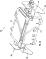
- FIGs. 1A-1C are representative perspective views of a novel high-voltage power distribution unit (HV PDU) 100, according to exemplary embodiments.
- the HV PDU 100 consists of a housing 114, which is open at the top, and a cover 112 to be disposed over the opening of the housing 114 for enclosing components therein.
- the housing 114 and the cover 112 together form a closed structure that is a rectangular cube structure.
- the HV PDU 100 supports three female connectors: an output female connector 106, a low voltage female connector 108, and an input female connector 110.
- the output female connector 106 and the low voltage female connector 108 are disposed on a first side of the housing 114 while the input female connector 110 is disposed on a second, opposite side of the housing.
- the output female connector 106, the low voltage female connector 108, and the input female connector 110 are plugged into the housing such that the connectors establish electrical connections to components within the housing 114 of the HV PDU 100.
- the HV PDU 100 features a first protection plate 102, disposed on the first side of the housing 114, and a second protection plate 104, disposed on the second side of the housing.
- the first protection plate 102 features an output receptacle 116 through which the output female connector 106 is fed and a low voltage receptacle 118 through which the low voltage female connector 108 is fed.
- the second protection plate 104 features an input receptacle 120 through which the input female connector 110 is fed.
- the first protection plate 102 and the second protection plate 104 are particularly designed to ensure safe maintenance of the HV PDU 100.
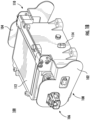
- FIGs. 2A-2B are representative views of the HV PDU 100 of FIGs. 1A-1C , according to exemplary embodiments.
- FIG. 2A is a side view featuring the first protection plate 102
- FIG. 2B is a side view featuring the second protection plate 104.
- the first protection plate 102 is adjacent and parallel to a first side of the housing 114 while the second protection plate 104 is adjacent and parallel to a second, opposite side of the housing.
- the housing 114 is thus sandwiched between the two protection plates 102 and 104.
- the first protection plate 102 includes the output receptacle 116, which surrounds the output female connector 106, and the low voltage receptacle 118, which surrounds the low voltage female connector 108.
- the first protection plate 102 has a front portion 214, a back portion 216, and a connector portion 218.
- the output receptacle 116 is located in the front portion 214 while the low voltage receptacle 118 is disposed between the front portion 214 and the back portion 216.
- the connector portion 218 is in a different plane than the front portion 214 and the back portion 216, whereas the front portion 214 and the back portion 216 are in the same plane (see FIG. 1B ).
- the front portion 214, the back portion 216, and the connector portion 218 are formed from a unitary material, such as metal, with the connector portion 218 being parallel to the front 214 and back 216 portions.
- the first protection plate 102 also includes a screw 202 and a screw 204, located in the connector portion 218, for securing the first protection plate 102 to the HV PDU 100.
- the screws 202 and 204 engage with the cover 112 of the HV PDU 100.
- the cover 112 has a front 210 and a back 212.
- the front 210 is on the left side and the back 212 is on the right side.
- the front 210 of the cover 112 is lifted upward and disengages from the housing 114 while the back 212 of the cover 112 remains connected to the housing 114, such as with a hinge.
- the first protection plate 102 which remains parallel to the side of the housing 114, rotates in an upward direction when the cover 112 is opened away from the housing 114.
- the front portion 214 of the first protection plate 102 is disposed above the housing 114 while the back portion 216 is blocking one or more of the output receptacle 116 and the low voltage receptacle 118.
- the second protection plate 104 includes the input receptacle 120, which surrounds the input female connector 110. Structurally, the second protection plate 104 has a front portion 220, a back portion 222, and a connector portion 224. The input receptacle 120 is located in the front portion 220.
- the connector portion 224 is in a different plane than the front portion 220 and the back portion 222, where the front portion 220 and the back portion 224 are in the same plane (see FIG. 1A ).
- the front portion 220, the back portion 222, and the connector portion 224 are formed from a unitary material, with the connector portion 224 being parallel to the front 220 and back 222 portions.
- the second protection plate 104 also includes a screw 206 and a screw 208, located in the connector portion 224, for securing the second protection plate 104 to the HV PDU 100.
- the screws 206 and 208 engage with the cover 112 of the HV PDU 100.
- the front 210 of the cover 112 on the right side and the back 212 of the cover 112 is on the left side.
- the front 210 is lifted upward and disengages from the housing 114 while the back 212 remains connected to the housing, such as with a hinge.
- the second protection plate 104 which remains parallel to the side of the housing 114, rotates in an upward direction when the cover 112 is opened away from the housing 114.
- the front portion 220 of the second protection plate 104 is disposed above the housing 114 while the back portion 222 is blocking the input receptacle 120.
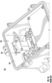
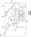
- FIGs. 3A-3B are representative drawings of an HV PDU 300, according to the prior art.
- FIG. 3A is an overhead perspective view of the interior and
- FIG. 3B is a side interior view of the HV PDU 300.
- the HV PDU 300 features a lid switch 304 disposed inside a housing 302.
- the lid switch 304 is located on an inside wall of the housing 302, opposite a female connector 306.
- the lid switch 304 features a microswitch 310 which includes a lever 308 designed to electrically disengage circuitry inside the HV PDU 300 as soon as the cover (not shown) is lifted from the housing 302.
- the lever 308 causes the circuitry inside the microswitch 310 to change from normally opened (NO) to normally closed (NC), and vice-versa, based on the movement of the cover.
- the lid switch 304 thus controls whether power is delivered to the HV PDU 300 when the cover is opened.
- the HV PDU 100 is different from the prior art HV PDU 300 in several ways.
- the HV PDU 100 is a special mechanical design in which the first protection plate 102, the second protection plate 104, or both the first and second protection plates, are mounted with the cover 112 to ensure a 100% power-off of the HV PDU 100 in response to opening of the cover 112.
- the mechanical design of the HV PDU 100 is more reliable than the lid switch 304 design of the prior art HV PDU 300.
- the HV PDU 100 may be implemented in multiple different ways, as described and illustrated below.
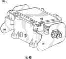
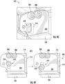
- FIGs. 4A-4F are representative drawings of a U-slot design implemented in the HV PDU 100, according to exemplary embodiments.
- FIG. 4A is a side cross-sectional view and FIG. 4B is a detailed cross-sectional view of the HV PDU 100
- FIG. 4C is a perspective view of the cover 112
- FIG. 4D is a perspective view of the U-slot portion of the HV PDU 100
- FIG. 4E is a detailed perspective view of the U-slot portion
- FIG. 4F is a detailed side view of implementation of the U-slot.
- the cover 112, housing 114, and the first protection plate 102 are visible in FIG. 4A . Because the view is a cross-section, the second protection plate 104 is not visible. A front join region 408 and a back join region 410 are shown, with the back join region 410 also featured in the detailed view of FIG. 4B .
- the cover 112 features a front post 404 and a back post 406 ( FIG. 4C ).
- the front post 404 occupies a post receptacle 402 ( FIG. 4B ) of the front join region 408 of the housing 114.
- the back post 406 occupies a second post receptacle (not shown) at the back join region 410 of the housing 114 ( FIG. 4A ).
- the front post 404 and back post 406 help to properly position the cover 112 over the housing 114.
- both the first protection plate 102 and the second protection plate 104 are shown, with the housing 114 and cover 112 sandwiched therebetween.
- a U-slot region 412 is also shown, with a detailed view of the U-slot region 412 in FIGs. 4E-4F .
- the U-slot region 412 is shown for the second protection plate 104, although the principles shown and described herein are also valid for the first protection plate 102.
- a U-slot 414 is disposed in the connector portion 224 of the second protection plate 104.
- a U-slot screw 416 fits into the U-slot 414 and is able to move vertically along the axis of the U-slot 414, in a downward direction.
- the U-slot screw 416 is attached to a bolt (not shown) that fits into the U-slot and is received by a generally circular bolt opening 418 of the housing 114 of the HV PDU 100 ( FIG. 4E ).
- the U-slot 414 is generally shaped like a flattened oval, pill-shaped, or U-shaped, but may be different than is shown, such as rectangular-shaped, e.g., as long as the width of the U-slot 414 is wider than the diameter of the bolt connected to the U-slot screw 416 but narrower than the U-slot screw 416.
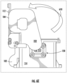
- FIG. 4F illustrates the changes that take place in the U-slot region 412 once the cover 112 of the HV PDU 100 is opened, according to exemplary embodiments.
- the U-slot screw 416 is disposed at the top of the U-slot 414.
- the cover 112 is flush against the housing 114.
- the cover 112 is opened, as indicated by the opening space 420 between the cover 112 and the housing 114 and the U-slot screw 416 is disposed at the bottom of the U-slot 414.
- the U-slot screw 416 thus moves downward vertically within the U-slot 414.
- the vertical movement of the U-slot screw 416 does not exceed the height of the front post 404 and back post 406. Further, in exemplary embodiments, the U-slot screw 416 is the rotating axis of the second protection plate 104. Thus, the second protection plate 104 has moved upward along with the movement of the cover 112.
- FIGs. 5A-5E are representative drawings of a hook design of the HV PDU 100, according to exemplary embodiments.
- FIG. 5A is a perspective view
- FIG. 5B is a detailed perspective view
- FIG. 5C is a side view of the second protection plate 104 with the hook feature
- FIG. 5D is a perspective view
- FIG. 5E is a detailed perspective view of the second protection plate 104 mated with the cover 112 using the hook feature.
- the second protection plate 104 is featured in FIGs. 5A-5E although the principles shown and described may be applied to the first protection plate 102 as well.
- FIG. 5A An inside view of the second protection plate 104 is shown in FIG. 5A .
- the second protection plate 104 includes the front portion 220, back portion 222, and connector portion 224 as before.
- the connector portion 224 there is a hook detail 502, which is illustrated in detail in FIG. 5B .
- the hook detail 502 features screw hole 506 and screw hole 508, with a hook 504 disposed therebetween.
- the hook 504 is a substantially rectangular-cube-shaped form attached to the connector portion 224 of the second protection plate 104, with a bent-up portion at the distal end, forming a hook-like appearance.
- the hook 504 is formed of the same material used for the second protection plate 104.
- FIG. 5C shows that the hook 504 is just above the U-slot region 412 with the screws 206 and 208 being on either side of the hook 504.
- a fitting detail 510 in FIGs. 5D-5E shows that the hook 504 fits into a hook slot 512 in the cover 112 of the HV PDU 100.
- FIG. 5E shows the features upside down, with the U-slot 414, which is beneath the hook detail 502 in FIG. 5C , being above the hook detail 502 in FIG. 5E .
- the screws 206 and 208 and the hook 504 help to secure the cover 112 to the second protection plate 104.
- the hook 504 ensures that, even if the screws 206 and 208 are removed, the second protection plate 104 nevertheless remains attached to the cover 112, which ensures safety during maintenance of the HV PDU 100.
- FIGs. 6A-6E are representative drawings of a bump ball design of the HV PDU 100, according to exemplary embodiments.
- FIG. 6A is a perspective view and FIG. 6B is a detailed perspective view of the bump ball design in the first protection plate 102;
- FIG. 6C is a perspective view and
- FIG. 6D is a detailed perspective view of the bump ball design in the housing 114;
- FIG. 6E is a side view of the HV PDU 100.
- the bump ball design is shown with for the first protection plate 102. However, the principles of the bump ball design are also applicable to the second protection plate 104.
- FIG. 6A An inside view of the first protection plate 102 is shown in FIG. 6A .
- the front portion 214, back portion 216, and connector portion 218 are shown as before.
- the output receptacle 116 (for receiving the output female connector 106) and the low voltage receptacle 118 (for receiving the low voltage female connector 108) are also shown.
- a bump ball design detail 602 is shown as part of the connector portion 218 of the first protection plate 102.
- the bump ball design detail 602 is shown more particularly in FIG. 6B .
- a bump ball 604 is shown in the connector portion 218 of the first protection plate 102. Like the hook 504, the bump ball 604 is on the inside of the connector portion 218, adjacent the side of the housing 114 where the first protection plate 102 is to be connected. The bump ball 604 is also adjacent the U-slot 414. In exemplary embodiments, the bump ball 604 is a convex protrusion on the inside of the connector portion 218. Although substantially spherical in shape, the bump ball 604 may alternatively be an elongated sphere or cylindrical in shape.
- FIG. 6C shows a bump ball detail 606 of the HV PDU 100 while a more detailed view is in FIG. 6D .
- the bump ball detail 606 is a fitting trough 608 disposed along a back surface of the housing 114.
- the fitting trough 608 is orthogonal to the back surface of the connector portion 218 of the first protection plate 102.
- the fitting trough 608 is also just beneath a screw housing 612 of the housing 114, with the cover 112 fitting into the screw housing 612.
- the bump ball 604 and the fitting trough 608 provide a mechanism to lock the first protection plate 102 in place once the cover 112 is opened. This helps to stabilize the cover 112 during maintenance, as components within the HV PDU 100 may be removed and other components added during the maintenance operation.
- the bump ball 604 and fitting trough 608 thus prevent movement of the cover 112 once the cover 112 is fully opened from the housing 114, in exemplary embodiments.
- FIG. 6E shows the second protection plate 104 rather than the first protection plate 102, but the same principles apply. Notice that, once the cover 112 is in this position with the bump ball 604 locked into the fitting trough 608, the back portion 222 of the second protection plate 104 blocks the input receptacle 120, as designed. Similarly, once the cover 112 is fully opened, the first protection plate 102 would block the output receptacle 116 and the low voltage receptacle 118.
- FIGs. 7A-7D are representative drawings of the HV PDU 100, in accordance with exemplary embodiments.
- FIG. 7A shows the HV PDU 100 as the female connectors are removed
- FIG. 7B shows the HV PDU 100 without the female connectors
- FIG. 7C is a detailed view of the second protection plate 104 as the U-bolt feature is engaged
- FIG. 7D shows the HV PDU 100 with the cover 112 rotated.
- the output female connector 106 and the input female connector 110 are removed from the HV PDU 100.
- the low voltage female connector 108 is also removed.
- Bolts connecting the cover 112 to the housing 114 are also removed.
- the cover 112 is secured using four bolts 702a, 702b, 702c, and 702d (collectively, “bolts 702") which feed into respective bolt receptacles 704a, 704b, 704c, and 704d (collectively, "bolt receptacles 704").
- the cover 112 may be secured to the housing 114 using more or fewer bolts 702.
- the bolts 702 may be removed from the bolt receptacles 704 before the output and input female connectors 106 and 110 are removed, and vice-versa.
- the HV PDU 100 after the bolts 702 and the connectors 106 and 110 are removed is shown in FIG. 7B .
- the cover 112 can be removed from the housing 114 of the HV PDU 100.
- the removal of the cover 112 causes the U-slot screw 416 to move upward in the U-slot 414, as illustrated in FIG. 7C .
- the opening space 420 shows that the cover 112 is moving away from the housing 114.
- the hook 504 is also securing the first protection plate 102 (or second protection plate 104) to the cover 112.
- FIG. 7D the cover 112 is fully opened and the bump ball 604 is seated in the fitting trough 608, thus ensuring that the cover 112 will not shut until maintenance is complete.
- the second protection plate 104 is blocking the input receptacle 120 from being able to receive the input female connector 110.
Landscapes
- Engineering & Computer Science (AREA)
- Microelectronics & Electronic Packaging (AREA)
- Power Engineering (AREA)
- Computer Security & Cryptography (AREA)
- Mechanical Engineering (AREA)
- Connector Housings Or Holding Contact Members (AREA)
- Details Of Connecting Devices For Male And Female Coupling (AREA)
Abstract
A high-voltage power distribution (100) unit includes a housing (114), a cover (112), and a protection plate (102, 104). The housing (114) holds an electrical device and has a top opening to receive the cover (112). Once the cover (112) is disposed over the housing (114), the housing (114) and the cover (112) form a closed structure. The protection plate (102, 104) is located on one side of the housing (114) and has a receptacle (116, 118) through which an output female connector (106, 108) fits.
Description
- A high-voltage power distribution unit (HV PDU) is an electrical box containing high-voltage DC contactors and fuses. The HV PDU may be enclosed in an IP67/6K9K-rated enclosure and may optimize power distribution using busbars and printed circuit board assemblies. The HV PDU may also feature temperature- and current-sensing capabilities to safely, reliably, and efficiently distribute power from a high-voltage battery module to the high-voltage systems of an environment, such as one supporting hybrid electric vehicles (HEVs).
- HV PDUs typically feature a housing and cover or lid for safely holding the components. During maintenance, power to the PDU is disabled and the lid is removed. Some PDUs feature lid switches that are designed to automatically disable power to the PDU as the lid is removed. If the lid switch is poorly designed or corroded, the components of the PDU may be powered despite the fact that the lid is opened, which may result in electric shock, fire, or worse.
- It is with respect to these and other considerations that present improvements may be useful.
- This summary is provided to introduce a selection of concepts in a simplified form that are further described below in the detailed description. This summary is not intended to identify key feature or essential features of the claimed subject matter, nor is it intended as an aid in determining the scope of the claimed subject matter.
- An exemplary embodiment of a high-voltage power distribution unit in accordance with the present disclosure may include a housing, a cover, and a protection plate. The housing holds an electrical device and has a top opening to receive the cover. Once the cover is disposed over the housing, the housing and the cover form a closed structure. The protection plate is located on one side of the housing and has a receptacle through which an output female connector fits.
- An exemplary embodiment of a power distribution unit in accordance with the present disclosure may include a housing with a cover and a protection plate. The cover is placed over a top opening of the housing to form a rectangular cube structure housing an electrical device. The protection plate has an output receptacle through for receiving an input female connector. The protection plate is connected to the cover. The cover is not removable from the housing until the input female connector is removed from the housing.
-
-
FIGs. 1A-1C are diagrams illustrating a high-voltage power distribution unit, in accordance with exemplary embodiments; -
FIGs. 2A-2B are diagrams illustrating the protection plates used in the high-voltage power distribution unit ofFIGs. 1A-1C , in accordance with exemplary embodiments; -
FIGs. 3A-3B are diagrams illustrating the lid switch design of a prior art high-voltage power distribution unit, in accordance with the prior art; -
FIGs. 4A-4F are diagrams illustrating a U slot design used in the high-voltage power distribution unit ofFIGs. 1A-1C , in accordance with exemplary embodiments; -
FIGs. 5A-5E are diagrams illustrating a hook design used in the high-voltage power distribution unit ofFIGs. 1A-1C , in accordance with exemplary embodiments; -
FIGs. 6A-6E are diagrams illustrating a bump ball design used in the high-voltage power distribution unit ofFIGs. 1A-1C , in accordance with exemplary embodiments; and -
FIGs. 7A-7D are diagrams illustrating steps for opening the cover of the high-voltage power distribution unit ofFIGs. 1A-1C , in accordance with exemplary embodiments; - A high-voltage power distribution unit (HV PDU) provides mechanical means to ensure that no power is issued to the PDU once the cover is removed. The HV PDU features a pair of protection plates disposed on either side of the PDU housing. The protection plates move in concert with the cover as the cover is removed from the housing. The HV PDU includes a U-slot design, a hook feature, and a bump ball feature to ensure high reliability and safety. The HV PDU needs not rely on poka-yoke processes or end of line process testing after assembly.
- For the sake of convenience and clarity, terms such as "top", "bottom", "upper", "lower", "vertical", "horizontal", "lateral", "transverse", "radial", "inner", "outer", "left", and "right" may be used herein to describe the relative placement and orientation of the features and components, each with respect to the geometry and orientation of other features and components appearing in the perspective, exploded perspective, and cross-sectional views provided herein. Said terminology is not intended to be limiting and includes the words specifically mentioned, derivatives therein, and words of similar import.
-
FIGs. 1A-1C are representative perspective views of a novel high-voltage power distribution unit (HV PDU) 100, according to exemplary embodiments. TheHV PDU 100 consists of ahousing 114, which is open at the top, and acover 112 to be disposed over the opening of thehousing 114 for enclosing components therein. In exemplary embodiments, thehousing 114 and thecover 112 together form a closed structure that is a rectangular cube structure. - The HV PDU 100 supports three female connectors: an output
female connector 106, a low voltagefemale connector 108, and an inputfemale connector 110. In exemplary embodiments, the outputfemale connector 106 and the low voltagefemale connector 108 are disposed on a first side of thehousing 114 while the inputfemale connector 110 is disposed on a second, opposite side of the housing. In exemplary embodiments, the outputfemale connector 106, the low voltagefemale connector 108, and the inputfemale connector 110 are plugged into the housing such that the connectors establish electrical connections to components within thehousing 114 of theHV PDU 100. - In exemplary embodiments, the HV PDU 100 features a
first protection plate 102, disposed on the first side of thehousing 114, and asecond protection plate 104, disposed on the second side of the housing. Thefirst protection plate 102 features anoutput receptacle 116 through which the outputfemale connector 106 is fed and alow voltage receptacle 118 through which the low voltagefemale connector 108 is fed. Thesecond protection plate 104 features aninput receptacle 120 through which the inputfemale connector 110 is fed. As will be shown and described herein, thefirst protection plate 102 and thesecond protection plate 104 are particularly designed to ensure safe maintenance of theHV PDU 100. -
FIGs. 2A-2B are representative views of theHV PDU 100 ofFIGs. 1A-1C , according to exemplary embodiments.FIG. 2A is a side view featuring thefirst protection plate 102 andFIG. 2B is a side view featuring thesecond protection plate 104. Thefirst protection plate 102 is adjacent and parallel to a first side of thehousing 114 while thesecond protection plate 104 is adjacent and parallel to a second, opposite side of the housing. Thehousing 114 is thus sandwiched between the twoprotection plates - As shown in
FIG. 2A , thefirst protection plate 102 includes theoutput receptacle 116, which surrounds the outputfemale connector 106, and thelow voltage receptacle 118, which surrounds the low voltagefemale connector 108. Structurally, thefirst protection plate 102 has afront portion 214, aback portion 216, and aconnector portion 218. Theoutput receptacle 116 is located in thefront portion 214 while thelow voltage receptacle 118 is disposed between thefront portion 214 and theback portion 216. - In some embodiments, the
connector portion 218 is in a different plane than thefront portion 214 and theback portion 216, whereas thefront portion 214 and theback portion 216 are in the same plane (seeFIG. 1B ). In some embodiments, thefront portion 214, theback portion 216, and theconnector portion 218 are formed from a unitary material, such as metal, with theconnector portion 218 being parallel to the front 214 and back 216 portions. - In exemplary embodiments, the
first protection plate 102 also includes ascrew 202 and ascrew 204, located in theconnector portion 218, for securing thefirst protection plate 102 to theHV PDU 100. In exemplary embodiments, thescrews cover 112 of theHV PDU 100. - The
cover 112 has a front 210 and aback 212. In the illustration ofFIG. 2A , the front 210 is on the left side and the back 212 is on the right side. When removed from thehousing 114, thefront 210 of thecover 112 is lifted upward and disengages from thehousing 114 while the back 212 of thecover 112 remains connected to thehousing 114, such as with a hinge. In exemplary embodiments, thefirst protection plate 102, which remains parallel to the side of thehousing 114, rotates in an upward direction when thecover 112 is opened away from thehousing 114. When this occurs, thefront portion 214 of thefirst protection plate 102 is disposed above thehousing 114 while theback portion 216 is blocking one or more of theoutput receptacle 116 and thelow voltage receptacle 118. - As shown in
FIG. 2B , thesecond protection plate 104 includes theinput receptacle 120, which surrounds the inputfemale connector 110. Structurally, thesecond protection plate 104 has afront portion 220, aback portion 222, and aconnector portion 224. Theinput receptacle 120 is located in thefront portion 220. - In some embodiments, the
connector portion 224 is in a different plane than thefront portion 220 and theback portion 222, where thefront portion 220 and theback portion 224 are in the same plane (seeFIG. 1A ). In some embodiments, thefront portion 220, theback portion 222, and theconnector portion 224 are formed from a unitary material, with theconnector portion 224 being parallel to the front 220 and back 222 portions. - In exemplary embodiments, the
second protection plate 104 also includes ascrew 206 and ascrew 208, located in theconnector portion 224, for securing thesecond protection plate 104 to theHV PDU 100. In exemplary embodiments, thescrews cover 112 of theHV PDU 100. - In the illustration of
FIG. 2B , thefront 210 of thecover 112 on the right side and the back 212 of thecover 112 is on the left side. When thecover 112 is removed from thehousing 114, the front 210 is lifted upward and disengages from thehousing 114 while the back 212 remains connected to the housing, such as with a hinge. In exemplary embodiments, thesecond protection plate 104, which remains parallel to the side of thehousing 114, rotates in an upward direction when thecover 112 is opened away from thehousing 114. When this occurs, thefront portion 220 of thesecond protection plate 104 is disposed above thehousing 114 while theback portion 222 is blocking theinput receptacle 120. - Thus, in exemplary embodiments, it is not possible to rotate the
first protection plate 102 until both the outputfemale connector 106 and the low voltagefemale connector 108 are removed (unplugged). Because thefirst protection plate 102 is connected to thecover 112, it is therefore also not possible to open thecover 112 until both the outputfemale connector 106 and the low voltagefemale connector 108 are removed (unplugged). - Likewise, in exemplary embodiments, it is not possible to rotate the
second protection plate 104 until the inputfemale connector 110 is removed. Because thesecond protection plate 104 is connected to thecover 112, it is also not possible to open thecover 112 until the inputfemale connector 110 is removed. -
FIGs. 3A-3B are representative drawings of anHV PDU 300, according to the prior art.FIG. 3A is an overhead perspective view of the interior andFIG. 3B is a side interior view of theHV PDU 300. TheHV PDU 300 features alid switch 304 disposed inside ahousing 302. Thelid switch 304 is located on an inside wall of thehousing 302, opposite afemale connector 306. As shown particularly inFIG. 3B , thelid switch 304 features amicroswitch 310 which includes a lever 308 designed to electrically disengage circuitry inside theHV PDU 300 as soon as the cover (not shown) is lifted from thehousing 302. The lever 308 causes the circuitry inside themicroswitch 310 to change from normally opened (NO) to normally closed (NC), and vice-versa, based on the movement of the cover. Thelid switch 304 thus controls whether power is delivered to theHV PDU 300 when the cover is opened. - Unfortunatley, the
lid switch 304 may be unreliable in operation. There may be a switch quality issue in which the lever 308 does not work as designed. Or, the lever 308 may set thelid switch 304 to NC or NO by mistake. During maintenance, thelid switch 304 is not easily observable until the cover of theHV PDU 300 has already been removed. The deficiencies of thelid switch 304 can result in failure of the PDU, electric shock, or worse. - The
HV PDU 100 is different from the priorart HV PDU 300 in several ways. TheHV PDU 100 is a special mechanical design in which thefirst protection plate 102, thesecond protection plate 104, or both the first and second protection plates, are mounted with thecover 112 to ensure a 100% power-off of theHV PDU 100 in response to opening of thecover 112. The mechanical design of theHV PDU 100 is more reliable than thelid switch 304 design of the priorart HV PDU 300. TheHV PDU 100 may be implemented in multiple different ways, as described and illustrated below. -
FIGs. 4A-4F are representative drawings of a U-slot design implemented in theHV PDU 100, according to exemplary embodiments.FIG. 4A is a side cross-sectional view andFIG. 4B is a detailed cross-sectional view of theHV PDU 100,FIG. 4C is a perspective view of thecover 112,FIG. 4D is a perspective view of the U-slot portion of theHV PDU 100,FIG. 4E is a detailed perspective view of the U-slot portion, andFIG. 4F is a detailed side view of implementation of the U-slot. - The
cover 112,housing 114, and thefirst protection plate 102 are visible inFIG. 4A . Because the view is a cross-section, thesecond protection plate 104 is not visible. Afront join region 408 and aback join region 410 are shown, with theback join region 410 also featured in the detailed view ofFIG. 4B . - In exemplary embodiments, as illustrated in
FIG. 4C , thecover 112 features afront post 404 and a back post 406 (FIG. 4C ). When thecover 112 is disposed upon thehousing 114, thefront post 404 occupies a post receptacle 402 (FIG. 4B ) of thefront join region 408 of thehousing 114. Similarly, theback post 406 occupies a second post receptacle (not shown) at theback join region 410 of the housing 114 (FIG. 4A ). In exemplary embodiments, thefront post 404 andback post 406 help to properly position thecover 112 over thehousing 114. - In the perspective veiw of the HV PDU 100 (
FIG. 4D ), both thefirst protection plate 102 and thesecond protection plate 104 are shown, with thehousing 114 and cover 112 sandwiched therebetween. AU-slot region 412 is also shown, with a detailed view of theU-slot region 412 inFIGs. 4E-4F . TheU-slot region 412 is shown for thesecond protection plate 104, although the principles shown and described herein are also valid for thefirst protection plate 102. - A
U-slot 414 is disposed in theconnector portion 224 of thesecond protection plate 104. AU-slot screw 416 fits into the U-slot 414 and is able to move vertically along the axis of theU-slot 414, in a downward direction. TheU-slot screw 416 is attached to a bolt (not shown) that fits into the U-slot and is received by a generally circular bolt opening 418 of thehousing 114 of the HV PDU 100 (FIG. 4E ). In exemplary embodiments, theU-slot 414 is generally shaped like a flattened oval, pill-shaped, or U-shaped, but may be different than is shown, such as rectangular-shaped, e.g., as long as the width of theU-slot 414 is wider than the diameter of the bolt connected to theU-slot screw 416 but narrower than theU-slot screw 416. -
FIG. 4F illustrates the changes that take place in theU-slot region 412 once thecover 112 of theHV PDU 100 is opened, according to exemplary embodiments. On the left side of the arrow, theU-slot screw 416 is disposed at the top of theU-slot 414. Thecover 112 is flush against thehousing 114. On the right side of the arrow, thecover 112 is opened, as indicated by the openingspace 420 between thecover 112 and thehousing 114 and theU-slot screw 416 is disposed at the bottom of theU-slot 414. TheU-slot screw 416 thus moves downward vertically within theU-slot 414. In exemplary embodiments, the vertical movement of theU-slot screw 416 does not exceed the height of thefront post 404 andback post 406. Further, in exemplary embodiments, theU-slot screw 416 is the rotating axis of thesecond protection plate 104. Thus, thesecond protection plate 104 has moved upward along with the movement of thecover 112. -
FIGs. 5A-5E are representative drawings of a hook design of theHV PDU 100, according to exemplary embodiments.FIG. 5A is a perspective view,FIG. 5B is a detailed perspective view, andFIG. 5C is a side view of thesecond protection plate 104 with the hook feature;FIG. 5D is a perspective view andFIG. 5E is a detailed perspective view of thesecond protection plate 104 mated with thecover 112 using the hook feature. Thesecond protection plate 104 is featured inFIGs. 5A-5E although the principles shown and described may be applied to thefirst protection plate 102 as well. - An inside view of the
second protection plate 104 is shown inFIG. 5A . Thesecond protection plate 104 includes thefront portion 220,back portion 222, andconnector portion 224 as before. In theconnector portion 224, there is ahook detail 502, which is illustrated in detail inFIG. 5B . Recall that thesecond protection plate 104 is connected to thecover 112 of theHV PDU 100 usingscrews 206 and 208 (FIG. 5C ). Thehook detail 502 features screwhole 506 andscrew hole 508, with ahook 504 disposed therebetween. In exemplary embodiments, thehook 504 is a substantially rectangular-cube-shaped form attached to theconnector portion 224 of thesecond protection plate 104, with a bent-up portion at the distal end, forming a hook-like appearance. In exemplary embodiments, thehook 504 is formed of the same material used for thesecond protection plate 104. -
FIG. 5C shows that thehook 504 is just above theU-slot region 412 with thescrews hook 504. Afitting detail 510 inFIGs. 5D-5E shows that thehook 504 fits into ahook slot 512 in thecover 112 of theHV PDU 100. Notice thatFIG. 5E shows the features upside down, with theU-slot 414, which is beneath thehook detail 502 inFIG. 5C , being above thehook detail 502 inFIG. 5E . Thus, in exemplary embodiments, thescrews hook 504 help to secure thecover 112 to thesecond protection plate 104. In exemplary embodiments, thehook 504 ensures that, even if thescrews second protection plate 104 nevertheless remains attached to thecover 112, which ensures safety during maintenance of theHV PDU 100. -
FIGs. 6A-6E are representative drawings of a bump ball design of theHV PDU 100, according to exemplary embodiments.FIG. 6A is a perspective view andFIG. 6B is a detailed perspective view of the bump ball design in thefirst protection plate 102;FIG. 6C is a perspective view andFIG. 6D is a detailed perspective view of the bump ball design in thehousing 114; andFIG. 6E is a side view of theHV PDU 100. The bump ball design is shown with for thefirst protection plate 102. However, the principles of the bump ball design are also applicable to thesecond protection plate 104. - An inside view of the
first protection plate 102 is shown inFIG. 6A . Thefront portion 214,back portion 216, andconnector portion 218 are shown as before. The output receptacle 116 (for receiving the output female connector 106) and the low voltage receptacle 118 (for receiving the low voltage female connector 108) are also shown. In exemplary embodiments, a bumpball design detail 602 is shown as part of theconnector portion 218 of thefirst protection plate 102. The bumpball design detail 602 is shown more particularly inFIG. 6B . - A
bump ball 604 is shown in theconnector portion 218 of thefirst protection plate 102. Like thehook 504, thebump ball 604 is on the inside of theconnector portion 218, adjacent the side of thehousing 114 where thefirst protection plate 102 is to be connected. Thebump ball 604 is also adjacent theU-slot 414. In exemplary embodiments, thebump ball 604 is a convex protrusion on the inside of theconnector portion 218. Although substantially spherical in shape, thebump ball 604 may alternatively be an elongated sphere or cylindrical in shape. -
FIG. 6C shows abump ball detail 606 of theHV PDU 100 while a more detailed view is inFIG. 6D . In thebump ball detail 606 is afitting trough 608 disposed along a back surface of thehousing 114. In exemplary embodiments, thefitting trough 608 is orthogonal to the back surface of theconnector portion 218 of thefirst protection plate 102. Thefitting trough 608 is also just beneath ascrew housing 612 of thehousing 114, with thecover 112 fitting into thescrew housing 612. In exemplary embodiments, when thecover 112 is opened (after the outputfemale connector 106 and low voltagefemale connector 108 of thefirst protection plate 102 are removed), thebump ball 604 fits into thefitting trough 608 once thecover 112 reaches an opening angle 610 (FIG. 6E ). - Thus, in exemplary embodiments, the
bump ball 604 and thefitting trough 608 provide a mechanism to lock thefirst protection plate 102 in place once thecover 112 is opened. This helps to stabilize thecover 112 during maintenance, as components within theHV PDU 100 may be removed and other components added during the maintenance operation. Thebump ball 604 andfitting trough 608 thus prevent movement of thecover 112 once thecover 112 is fully opened from thehousing 114, in exemplary embodiments. -
FIG. 6E shows thesecond protection plate 104 rather than thefirst protection plate 102, but the same principles apply. Notice that, once thecover 112 is in this position with thebump ball 604 locked into thefitting trough 608, theback portion 222 of thesecond protection plate 104 blocks theinput receptacle 120, as designed. Similarly, once thecover 112 is fully opened, thefirst protection plate 102 would block theoutput receptacle 116 and thelow voltage receptacle 118. -
FIGs. 7A-7D are representative drawings of theHV PDU 100, in accordance with exemplary embodiments.FIG. 7A shows theHV PDU 100 as the female connectors are removed,FIG. 7B shows theHV PDU 100 without the female connectors,FIG. 7C is a detailed view of thesecond protection plate 104 as the U-bolt feature is engaged, andFIG. 7D shows theHV PDU 100 with thecover 112 rotated. - In
FIG. 7A , the outputfemale connector 106 and the inputfemale connector 110 are removed from theHV PDU 100. Although not shown, the low voltagefemale connector 108 is also removed. Bolts connecting thecover 112 to thehousing 114 are also removed. In exemplary embodiments, thecover 112 is secured using fourbolts respective bolt receptacles cover 112 may be secured to thehousing 114 using more or fewer bolts 702. The order of removal does not matter, the bolts 702 may be removed from the bolt receptacles 704 before the output and inputfemale connectors HV PDU 100 after the bolts 702 and theconnectors FIG. 7B . - At this stage, the
cover 112 can be removed from thehousing 114 of theHV PDU 100. The removal of thecover 112 causes theU-slot screw 416 to move upward in theU-slot 414, as illustrated inFIG. 7C . The openingspace 420 shows that thecover 112 is moving away from thehousing 114. Thehook 504 is also securing the first protection plate 102 (or second protection plate 104) to thecover 112. InFIG. 7D , thecover 112 is fully opened and thebump ball 604 is seated in thefitting trough 608, thus ensuring that thecover 112 will not shut until maintenance is complete. In this fully opened position, thesecond protection plate 104 is blocking theinput receptacle 120 from being able to receive the inputfemale connector 110. - As used herein, an element or step recited in the singular and proceeded with the word "a" or "an" should be understood as not excluding plural elements or steps, unless such exclusion is explicitly recited. Furthermore, references to "one embodiment" of the present disclosure are not intended to be interpreted as excluding the existence of additional embodiments that also incorporate the recited features.
- While the present disclosure refers to certain embodiments, numerous modifications, alterations, and changes to the described embodiments are possible without departing from the sphere and scope of the present disclosure, as defined in the appended claim(s). Accordingly, it is intended that the present disclosure is not limited to the described embodiments, but that it has the full scope defined by the language of the following claims, and equivalents thereof.
Claims (15)
- A high-voltage power distribution unit comprising:a housing to hold an electrical device, the housing having a top opening;a cover to be placed over the top opening, wherein the housing and the cover form a closed structure; anda protection plate disposed on a first side of the housing, the protection plate having an output receptacle through which an output female connector fits.
- The high-voltage power distribution unit of claim 1, wherein the cover cannot be moved away from the housing until the output female connector is unplugged from the housing.
- The high-voltage power distribution unit of claim 1 or 2, wherein the protection plate is coupled to the cover using a screw.
- The high-voltage power distribution unit of claim 3, wherein the protection plate further comprises a connector portion to couple the protection plate to the cover, the connector portion further comprising a U-slot to receive a second screw, wherein the second screw moves vertically downward in the U-slot as the cover is removed from the housing.
- The high-voltage power distribution unit of claim 4, wherein the connector portion further comprises a hook disposed between the screw and a third screw, wherein the hook fits into a hook slot of the cover.
- The high-voltage power distribution unit of claim 5, the connector portion further comprising a bump ball disposed adjacent the U-slot, wherein the bump ball fits into a fitting trough of the housing when the cover is fully opened from the housing.
- The high-voltage power distribution unit of claim 6, wherein the bump ball is a convex protrusion disposed on an inside surface of the connector portion of the protection plate.
- The high-voltage power distribution unit of any of the preceding claims, further comprising a second protection plate disposed on a second side of the housing, the second side being opposite the first side, the second protection plate having an input receptacle through which an input female connector fits.
- The high-voltage power distribution unit of claim 8, wherein the cover cannot be moved away from the housing until the input female connector is unplugged from the housing.
- The high-voltage power distribution unit of claim 8 or 9, wherein the second protection plate further comprises a connector portion to couple the second protection plate to the cover, the connector portion further comprising a U-slot to receive a screw, wherein the screw moves vertically downward in the U-slot as the cover is removed from the housing, preferably wherein the connector portion further comprises a hook disposed between a second screw and a third screw, wherein the hook fits into a hook slot of the cover, more preferably the connector portion further comprising a bump ball disposed adjacent the U-slot, wherein the bump ball fits into a fitting trough of the housing when the cover is fully opened from the housing.
- A power distribution unit comprising:a housing with a cover placed over a top opening of the housing, the housing and cover forming a rectangular cube structure housing an electrical device; anda protection plate having an input receptacle through which an input female connector fits, wherein the protection plate is coupled to the cover;wherein the cover is not removable from the housing until the input female connector is removed from the housing.
- The power distribution unit of claim 11, further comprising a second protection plate having an output receptacle through which an output female connector fits, preferably wherein the second protection plate is coupled to the cover and the cover is not removable from the housing until the output female connector is removed from the housing.
- The power distribution unit of claim 11 or 12, wherein the protection plate further comprises a hook disposed between a pair of screws, wherein the hook fits into a hook slot of the cover, preferably wherein the cover further comprises a bolt and the housing comprises a bolt receptacle, wherein the cover is secured to the housing by feeding the bolt into the bolt receptacle, more preferably wherein the bolt is removed from the bolt receptacle before the cover is removed from the housing.
- The power distribution unit of any of the preceding claims 11-13, wherein the protection plate further comprises a U-slot and a screw that fits through the U-slot and is received into a screw hole of the cover, wherein the screw moves vertically in a downward direction inside the U-slot in response to the cover being removed from the housing, preferably wherein the protection plate further comprises a bump ball disposed on an inside surface of the protection plate adjacent the housing, wherein the bump ball is received into a fitting trough of the housing when the cover is fully opened, wherein the bump ball and fitting trough prevent movement of the cover.
- Use of a high voltage distribution unit according to any of the preceding claims 1-10, or a power distribution unit according to any of the claims 11-14 for distributing high voltage power.
Applications Claiming Priority (1)
| Application Number | Priority Date | Filing Date | Title |
|---|---|---|---|
| CN202311425630.9A CN119921196A (en) | 2023-10-31 | 2023-10-31 | High voltage power distribution unit |
Publications (1)
| Publication Number | Publication Date |
|---|---|
| EP4550595A1 true EP4550595A1 (en) | 2025-05-07 |
Family
ID=93214856
Family Applications (1)
| Application Number | Title | Priority Date | Filing Date |
|---|---|---|---|
| EP24207859.0A Pending EP4550595A1 (en) | 2023-10-31 | 2024-10-21 | High-voltage power distribution unit |
Country Status (3)
| Country | Link |
|---|---|
| US (1) | US20250141194A1 (en) |
| EP (1) | EP4550595A1 (en) |
| CN (1) | CN119921196A (en) |
Citations (4)
| Publication number | Priority date | Publication date | Assignee | Title |
|---|---|---|---|---|
| US5504655A (en) * | 1994-06-10 | 1996-04-02 | Westinghouse Electric Corp. | Electric vehicle power distribution module |
| DE102010001411A1 (en) * | 2010-02-01 | 2011-08-04 | Tyco Electronics AMP GmbH, 64625 | Housing for electrical circuit of high-voltage application, has cover plate to allows access to access area utilized for actuating fixing device and to block access to connecting area, when cover plate is in open position |
| US9543693B2 (en) * | 2013-02-01 | 2017-01-10 | Robert Bosch Gmbh | High-voltage arrangement |
| CN115224537A (en) * | 2021-04-16 | 2022-10-21 | 冷王公司 | Electrical connection unit |
-
2023
- 2023-10-31 CN CN202311425630.9A patent/CN119921196A/en active Pending
-
2024
- 2024-10-21 EP EP24207859.0A patent/EP4550595A1/en active Pending
- 2024-10-29 US US18/930,024 patent/US20250141194A1/en active Pending
Patent Citations (4)
| Publication number | Priority date | Publication date | Assignee | Title |
|---|---|---|---|---|
| US5504655A (en) * | 1994-06-10 | 1996-04-02 | Westinghouse Electric Corp. | Electric vehicle power distribution module |
| DE102010001411A1 (en) * | 2010-02-01 | 2011-08-04 | Tyco Electronics AMP GmbH, 64625 | Housing for electrical circuit of high-voltage application, has cover plate to allows access to access area utilized for actuating fixing device and to block access to connecting area, when cover plate is in open position |
| US9543693B2 (en) * | 2013-02-01 | 2017-01-10 | Robert Bosch Gmbh | High-voltage arrangement |
| CN115224537A (en) * | 2021-04-16 | 2022-10-21 | 冷王公司 | Electrical connection unit |
Also Published As
| Publication number | Publication date |
|---|---|
| CN119921196A (en) | 2025-05-02 |
| US20250141194A1 (en) | 2025-05-01 |
Similar Documents
| Publication | Publication Date | Title |
|---|---|---|
| US7573232B2 (en) | Battery exchange apparatus and method for uninterruptible power supply | |
| US6428363B2 (en) | Connecting structure for battery terminals | |
| US11611133B2 (en) | Manual service disconnect for a battery system | |
| US8657613B2 (en) | Electrical charger | |
| US6946217B2 (en) | Battery lock | |
| US6366449B1 (en) | Power supply shut-off apparatus | |
| ES3061782T3 (en) | Battery pack and vehicle containing battery pack | |
| US8579655B2 (en) | Device connector | |
| JP3820355B2 (en) | Power circuit breaker | |
| US10003157B2 (en) | Service plug unit, device unit, and power cutting-off system for electric car comprising same | |
| JPH1083753A (en) | Service plug | |
| US8460027B2 (en) | Interlock for an electrical system | |
| US5763830A (en) | Structure and connection for housing active components in a modular-replaceable inner container for cable television signal transmission | |
| EP4550595A1 (en) | High-voltage power distribution unit | |
| US20210242541A1 (en) | Energy storage apparatus | |
| JPH09265874A (en) | Circuit breaker device | |
| US7714693B2 (en) | Slow blow fuse and electric junction box | |
| EP4203202B1 (en) | Integrated quick disconnect connector | |
| CN112710960A (en) | Integrated MSD connector test box for testing power battery | |
| KR20230017765A (en) | battery connector | |
| CN115732955A (en) | electrical junction box | |
| CN213936420U (en) | Battery module and unmanned aerial vehicle | |
| US12224517B2 (en) | Electrical junction box | |
| CN215835716U (en) | Plug-in module and module box | |
| CN215266929U (en) | Connector assembly |
Legal Events
| Date | Code | Title | Description |
|---|---|---|---|
| PUAI | Public reference made under article 153(3) epc to a published international application that has entered the european phase |
Free format text: ORIGINAL CODE: 0009012 |
|
| STAA | Information on the status of an ep patent application or granted ep patent |
Free format text: STATUS: THE APPLICATION HAS BEEN PUBLISHED |
|
| AK | Designated contracting states |
Kind code of ref document: A1 Designated state(s): AL AT BE BG CH CY CZ DE DK EE ES FI FR GB GR HR HU IE IS IT LI LT LU LV MC ME MK MT NL NO PL PT RO RS SE SI SK SM TR |
|
| STAA | Information on the status of an ep patent application or granted ep patent |
Free format text: STATUS: REQUEST FOR EXAMINATION WAS MADE |
|
| 17P | Request for examination filed |
Effective date: 20251106 |