EP4550587A1 - Serration feature based clearance compensation mechanism for an electrical connector - Google Patents
Serration feature based clearance compensation mechanism for an electrical connector Download PDFInfo
- Publication number
- EP4550587A1 EP4550587A1 EP23206989.8A EP23206989A EP4550587A1 EP 4550587 A1 EP4550587 A1 EP 4550587A1 EP 23206989 A EP23206989 A EP 23206989A EP 4550587 A1 EP4550587 A1 EP 4550587A1
- Authority
- EP
- European Patent Office
- Prior art keywords
- teeth
- connector housing
- electrical connector
- connector system
- assist device
- Prior art date
- Legal status (The legal status is an assumption and is not a legal conclusion. Google has not performed a legal analysis and makes no representation as to the accuracy of the status listed.)
- Pending
Links
Images



Classifications
-
- H—ELECTRICITY
- H01—ELECTRIC ELEMENTS
- H01R—ELECTRICALLY-CONDUCTIVE CONNECTIONS; STRUCTURAL ASSOCIATIONS OF A PLURALITY OF MUTUALLY-INSULATED ELECTRICAL CONNECTING ELEMENTS; COUPLING DEVICES; CURRENT COLLECTORS
- H01R13/00—Details of coupling devices of the kinds covered by groups H01R12/70 or H01R24/00 - H01R33/00
- H01R13/62—Means for facilitating engagement or disengagement of coupling parts or for holding them in engagement
- H01R13/629—Additional means for facilitating engagement or disengagement of coupling parts, e.g. aligning or guiding means, levers, gas pressure electrical locking indicators, manufacturing tolerances
- H01R13/62933—Comprising exclusively pivoting lever
- H01R13/62944—Pivoting lever comprising gear teeth
-
- H—ELECTRICITY
- H01—ELECTRIC ELEMENTS
- H01R—ELECTRICALLY-CONDUCTIVE CONNECTIONS; STRUCTURAL ASSOCIATIONS OF A PLURALITY OF MUTUALLY-INSULATED ELECTRICAL CONNECTING ELEMENTS; COUPLING DEVICES; CURRENT COLLECTORS
- H01R13/00—Details of coupling devices of the kinds covered by groups H01R12/70 or H01R24/00 - H01R33/00
- H01R13/62—Means for facilitating engagement or disengagement of coupling parts or for holding them in engagement
- H01R13/627—Snap or like fastening
- H01R13/6271—Latching means integral with the housing
- H01R13/6272—Latching means integral with the housing comprising a single latching arm
-
- H—ELECTRICITY
- H01—ELECTRIC ELEMENTS
- H01R—ELECTRICALLY-CONDUCTIVE CONNECTIONS; STRUCTURAL ASSOCIATIONS OF A PLURALITY OF MUTUALLY-INSULATED ELECTRICAL CONNECTING ELEMENTS; COUPLING DEVICES; CURRENT COLLECTORS
- H01R13/00—Details of coupling devices of the kinds covered by groups H01R12/70 or H01R24/00 - H01R33/00
- H01R13/62—Means for facilitating engagement or disengagement of coupling parts or for holding them in engagement
- H01R13/629—Additional means for facilitating engagement or disengagement of coupling parts, e.g. aligning or guiding means, levers, gas pressure electrical locking indicators, manufacturing tolerances
- H01R13/62933—Comprising exclusively pivoting lever
- H01R13/62955—Pivoting lever comprising supplementary/additional locking means
-
- H—ELECTRICITY
- H01—ELECTRIC ELEMENTS
- H01R—ELECTRICALLY-CONDUCTIVE CONNECTIONS; STRUCTURAL ASSOCIATIONS OF A PLURALITY OF MUTUALLY-INSULATED ELECTRICAL CONNECTING ELEMENTS; COUPLING DEVICES; CURRENT COLLECTORS
- H01R13/00—Details of coupling devices of the kinds covered by groups H01R12/70 or H01R24/00 - H01R33/00
- H01R13/62—Means for facilitating engagement or disengagement of coupling parts or for holding them in engagement
- H01R13/639—Additional means for holding or locking coupling parts together, after engagement, e.g. separate keylock, retainer strap
Definitions
- the present disclosure generally relates to a mechanism for clearance compensation in an electrical connector system. More specifically, it discloses an electrical connector system having pluralities of teeth provided on members thereof which are adapted to be engaged with each other and thereby to enable different locking positions of the electrical connector system.
- an electrical connector system comprises a first member, for example, a female component which is often referred to as a socket, and a corresponding second member, for example, a male component which is often referred to as a plug.
- an electrical connector system additionally comprises a mate assist device to facilitate establishing a mated state of the members of the electrical connector system.
- the object of the disclosed subject matter is to overcome disadvantages of the prior art electrical connector systems, particularly, to provide an electrical connector system that is adapted to advantageously provide compensation of manufacturing tolerances of components of such electrical connector system.
- an electrical connector system comprising a connector housing, a mate assist device and locking means.
- the connector housing holds (is adapted for holding) one or more electrical contact elements.
- the mate assist device is associated with the connector housing and, as generally known to the skilled person, is adapted to facilitate establishing a mate state of the connector housing with a corresponding counter connector housing.
- the locking means are adapted for locking the mate assist device relative to the connector housing such that, as generally known to the skilled person, relative movement of the mate assist device relative to the connector housing is blocked (e.g., until the locking means are unlocked).
- the locking means comprise a first plurality of teeth associated with (e.g., attached to, formed on, or the like) the connector housing.
- the locking means comprise a second plurality of teeth associated with (e.g., attached to, formed on, or the like) the mate assist device.
- the first and second plurality of teeth are adapted to be engaged with each other. Engaging the teeth enables establishing different locking positions of the mate assist device relative to the connector housing in a mated state of the connector housing with a corresponding counter connector housing.
- the mate assist device may be locked relative to the connector housing (and hence the connector housing relative to the corresponding counter connector housing) in a position that advantageously compensates manufacturing tolerances of various components of the electrical connector system.
- an electrical connector system comprising a first connector housing, a corresponding second connector housing and locking means.
- Each of the two connector housings holds (is adapted for holding) one or more electrical contact elements.
- the locking means are adapted for locking the two housings with each other such that, as generally known by the skilled person, relative movement of the two housings relative to each other is blocked (e.g., until the locking means are unlocked).
- the locking means comprise a first plurality of teeth associated with (e.g., attached to, formed on, or the like) the first connector housing.
- the locking means comprise a second plurality of teeth associated with (e.g., attached to, formed on, or the like) the corresponding second plurality of teeth.
- the first and second plurality of teeth are adapted to be engaged with each other. Engaging the teeth enables establishing different locking positions of the first connector housing relative to the corresponding second connector housing in a mated state of the electrical connector system. As a result, the first connector housing may be locked relative to the corresponding second connector housing in a position that advantageously compensates manufacturing tolerances of various components of the electrical connector system.
- each of the first plurality of teeth and the second plurality of teeth comprises a saw-tooth geometry.
- the locking means when engaged, may advantageously withstand forces acting upon the locking means which are transferred thereon from other components of the electrical connector system.
- the first plurality of teeth and the second plurality are each respectively arranged in a tooth rack.
- the respective electrical connector system may advantageously assume different locking positions in a stepwise manner, for example, in equidistant steps.
- the first plurality of teeth and the second plurality of teeth are adapted to allow relative movement with each other in only one direction, when engaged.
- the respective electrical connector system when the locking means are engaged, may advantageously offer a ratchet-like functionality.
- the connector housing comprises a locking latch for locking the mate assist device in the mated state.
- the first plurality of teeth is provided on the locking latch.
- the locking means may be advantageously locked and unlocked by operating the locking latch to respectively engage or disengage the first and second plurality of teeth with each other.
- the locking latch may be at least partially accessible in the mated state of the connector housing with the corresponding counter connector housing.
- the electrical connector system further comprises an unlocking arm.
- the unlocking arm is accessible when the two housings are in the mated state.
- the unlocking arm is arranged such that, when the unlocking arm is operated, the unlocking arm disengages the first and second plurality of teeth.
- the mate assist device comprises a lever.
- the second plurality of teeth is provided on the lever.
- the locking means are advantageously applied to a lever-based mate assist system.
- the mate assist device comprises a slider.
- the second plurality of teeth is provided on the slide.
- the mate assist device comprises a cam-lever system.
- the second plurality of teeth is provided on a cam of the cam-lever system.
- each of the first plurality of teeth and the second plurality of teeth comprises at least two teeth.
- plural different locking positions may be advantageously enabled while the number of teeth and their footprint may be advantageously optimized.
- each of the first plurality of teeth and the second plurality of teeth comprises at least three teeth, at least four teeth, or at least five teeth.
- a tradeoff between a number of teeth (and hence a number of different locking positions) and their footprint may be advantageously established.
- the different locking positions are at least two locking positions.
- plural different locking positions may be advantageously enabled while the number of teeth and their footprint may be optimized.
- the different locking position are at least three locking positions, at least four locking positions, or at least five locking positions. As a result, a tradeoff between a number of different locking positions (and hence a number of teeth) and their footprint may be advantageously established.
- the different locking positions are arranged to provide compensation of manufacturing tolerances of components of the electrical connector system. As a result, quality of the electrical contact between respective electrical contact elements of the electrical connector systems may be advantageously enhanced.
- the electrical connector system further comprises the corresponding counter connector housing.
- Fig. 1A shows - in a three-dimensional view - a connector housing 102 of an electrical connector system 100 according to an embodiment of the present disclosure.
- the connector housing 102 comprises a portion 104 for mating with a corresponding counter connectors housing (not shown). Further, the connector housing 102 comprises a portion 106 adapted for associating the connector housing 102 with a mate assist device 150 (not shown in Fig. 1A but explained in conjunction with Fig. 1B ).
- the mate assist device 150 is associated with the connector housing 102 such that it is rotatably movable around the axis of the hole in the portion 106 of the connector housing 102.
- the connector housing 102 further comprises a locking latch 108 having a plurality of teeth 110 formed thereon.
- the plurality of teeth 110 and a further plurality of teeth 156 (not shown in Fig. 1A but explained in conjunction with Fig. 1B ) formed on the mate assist device 150 compose an embodiment of locking means of the present disclosure.
- a portion 112 of the locking latch 108 is accessible and is adapted to be operable (e.g., by the user) to facilitate locking and unlocking the locking means.
- the first plurality of teeth 110 comprises a saw-tooth geometry and is formed as a tooth rack.
- Fig. 1B shows - in a three-dimensional view - a mate assist device 150 of the electrical connector system 100 according to an embodiment of the present disclosure.
- the mate assist device 150 comprises portions 152 (corresponding to the portion 106 of the connector housing 102) which is adapted for associating the mate assist device 150 with the connector housing 102.
- the mate assist device 150 comprises gear elements 154 which are adapted for meshing with corresponding gear elements 206 (not shown in Fig. 1B but explained in conjunction with Fig. 2D ) of the counter connector housing (not shown).
- the mate assist device 150 comprises a plurality of teeth 156 formed thereon.
- the second plurality of teeth 156 comprises a saw-tooth geometry and is formed as a tooth rack.
- the number of teeth of the second plurality of teeth 156 of the mate assist device 150 is less than the number of teeth of the first plurality of teeth 110 of the connector housing 102 (explained in conjunction with Fig. 1A ). However, the skilled person recognizes that various constellations of the respective numbers of teeth may be advantageously applied.
- the plurality of teeth 110 (shown in Fig. 1A ) and the plurality of teeth 156 compose an embodiment of locking means of the present disclosure.
- the second plurality of teeth 156 comprises a saw-tooth geometry and is formed as a tooth rack.
- Fig. 2A shows - in a cross section view - a section of the connector housing 102 and a section of the mate assist device 150 of the electrical connector system 100 according to an embodiment of the present disclosure.
- the position of the connector housing 102 and the mate assist device 150 relative to each other corresponds to an unmated state of the connector housing 102 with the corresponding counter connector housing (not shown).
- the plurality of teeth 110 and the plurality of teeth 156 are not engaged with each other.
- Fig. 2A shows the locking latch 108 and the portion 112 of the locking latch 108 which are described in the context of Fig. 1A . For simplicity, these two portions are not referenced again in Figs. 2B and 2C .
- Fig. 2B shows - in a cross section view - a section of the connector housing 102 and a section of the mate assist device 150 of the electrical connector system 100 according to an embodiment of the present disclosure.
- the position of the connector housing 102 and the mate assist device 150 relative to each other corresponds to a mated state of the connector housing and the corresponding counter connector housing (not shown).
- the plurality of teeth 110 of the connector housing 102 and the plurality of teeth 156 of the mate assist device 150 are engaged with each other. This means that relative movement of the mate assist device 150 relative to the connector housing 102 is blocked.
- the position of the connector housing 102 and the mate assist device 150 relative to each other may be referred to as a locking position of the electrical connector systems.
- the skilled person recognizes that the two pluralities of teeth 110 and 156 provide different locking positions.
- the locking position shown in Fig. 2B is a position defined solely by design of components of the electrical connector system 100 and is marked by a dashed line 200.
- the locking position indicated by the line 200 corresponds to the theoretical case in which manufacturing tolerances are neglected.
- the saw-tooth geometry allows their relative movement with each other in only one direction and may be regarded as offering a ratchet-like functionality.
- Fig. 2C shows - in a cross section view - a section of the connector housing 102 and a section of the mate assist device 150 of the electrical connector system 100 according to an embodiment of the present disclosure.
- the position of the connector housing 102 and the mate assist device 150 relative to each other correspond to the mated state.
- manufacturing tolerances are considered. This results in the locking position of the plurality of teeth 110 and the plurality of teeth 156 being shifted from the theoretical case indicated by the line 200 to the left-hand side (counterclockwise).
- the actual locking position is marked by a dashed line 202 and its deviation from theoretical case is indicated by two curved arrows pointing respectively to the lines 200 and 202.
- the locking position indicated by the line 202 corresponds to the mated state in which manufacturing tolerances are compensated due to displacement of the mate assist device 150 anticlockwise beyond the line 200.
- This displacement results in enhanced quality of electrical contact between respective electrical contact elements (for holding of which the connector housing 102 and the corresponding counter connector housing are adapted).
- Due to integration of the locking means (the first plurality of teeth 110 and the second plurality of teeth 156) with the connector housing 102 and the mate assist device 150 no additional burden for the user of the electrical connector system 100 arises - beyond the usual mating of the connector housing 102 with the mate assist device 150.
- Fig. 2D shows - in a cross section view - a section of the connector housing 102, a section of the mate assist device 150 and a section of the corresponding counter connector housing 204 of the electrical connector system 100 according to an embodiment of the present disclosure. Further, one of the gear elements 154 of the mate assist device 150 and corresponding gear elements 206 of the counter connector housing 204 are shown.
- the displacement between the lines 200 and 202 explained in Fig. 2C results in an angular displacement of the mate assist device 150 in a counterclockwise direction which leads to a force acting upon the gear elements 206 as indicated by an arrow 208. This force results in tightening of the mating state of the connector housing 102 and the counter connector housing 204 along their mating direction indicated by an arrow 210.
- Fig. 3A shows schematically an initial phase of an unlocking process of the connector housing 102 and the mate assist device 150 of the electrical connector system 100 according to an embodiment of the present disclosure.
- the connector housing 102 and their mate assist device 150 Prior to the initial phase of the unlocking process, the connector housing 102 and their mate assist device 150 are in the mated state; the first plurality of teeth 110 and the second plurality of teeth 156 are engaged with each other in their locking position.
- An arrow 300 indicates a direction of a force to be exerted upon the portion 112 of the locking latch 108 in order to unlock the locking means (i.e., to effectuate disengagement of the first plurality of teeth 110 and the second plurality of teeth 156 from each other). This direction is essentially parallel to teeth flanks carrying engaging forces between the first plurality of teeth 110 and the second plurality of teeth 156.
- Fig. 3B shows schematically a further phase of an unlocking process of the connector housing 102 and the mate assist device 150 of the electrical connector system 100 according to an embodiment of the present disclosure.
- Pressing the portion 112 of the locking latch 108 in the direction explained in Fig. 3A results in disengagement of the first plurality of teeth 110 and the second plurality of teeth 156 from each other.
- rotating the mate assist device 150 clockwise - as indicated by an arrow 302 - transitions the electrical connector system 100 to its unmated state.
- Fig. 4A shows - in a three-dimensional view - an electrical connector system 400 comprising a first connector housing 402 and a second connector housing 404.
- the electrical connector system 400 further comprises an unlocking arm 406 which is accessible and adapted to be operable (e.g., by the user) to facilitate unlocking the electrical connector system as explained in conjunction with Fig. 4B below.
- the electrical connector system 400 is not equipped with any mate assist.
- Fig. 4B shows - in a cross section view - a section of the electrical connector system 400.
- the first connector housing 402 comprises an interface member 408 adapted to (e.g., in a mated state of the electrical connector system 400) penetrate the second connector housing 404.
- the first connector housing 402 further comprises a first plurality of teeth 410 formed on the interface member 408.
- the second connector housing 404 comprises a locking tongue member 412 having a second plurality of teeth 414 formed thereon.
- the first plurality of teeth 410 and the second plurality of teeth 414 compose an embodiment of locking means of the present disclosure.
- the first plurality of teeth 410 and the second plurality of teeth 414 are engaged with each other.
- the position of the first connector housing 402 and the second connector housing 404 relative to each other may be referred to as a locking position of the electrical connector system 400.
- the skilled person recognizes that the two pluralities of teeth 410 and 414 provide different locking positions - similar as the locking means explained above in conjunction with the electric connector 100.
- the unlocking arm 406 is arranged such that, when the unlocking arm is operated (e.g., by the user), the unlocking arm exerts a force upon the interface member 408 resulting in disengagement of the first plurality of teeth 410 and the second plurality of teeth 414 from each other and thereby enables transition of the electrical connector system 400 to its unmated state.
Landscapes
- Details Of Connecting Devices For Male And Female Coupling (AREA)
Abstract
The present disclosure relates to a mechanism for clearance compensation in an electrical connector system. An electrical connector system (100) is provided. The electrical connector system (100) comprises a connector housing (102) adapted for holding one or more electrical contact elements, a mate assist device (150) associated with the connector housing (102), and locking means for locking the mate assist device (150) relative to the connector housing. The locking means comprise a first plurality of teeth (110) associated with the connector housing (102) and a second plurality of teeth (156) associated with the mate assist device (150). The first plurality of teeth (110) and the second plurality of teeth (156) are adapted to be engaged with each other and thereby to enable different locking positions of the mate assist device (150) relative to the connector housing (102) in a mated state of the connector housing (102) with a corresponding counter connector housing.

Description
- The present disclosure generally relates to a mechanism for clearance compensation in an electrical connector system. More specifically, it discloses an electrical connector system having pluralities of teeth provided on members thereof which are adapted to be engaged with each other and thereby to enable different locking positions of the electrical connector system.
- Electrical connector systems are generally used to provide a removable electrical connection between respective electrical contact elements arranged in their members. Typically, an electrical connector system comprises a first member, for example, a female component which is often referred to as a socket, and a corresponding second member, for example, a male component which is often referred to as a plug. In some cases, an electrical connector system additionally comprises a mate assist device to facilitate establishing a mated state of the members of the electrical connector system. When the members of the electrical connector system are mated in accordance with their respective positions defined solely by design, various factors such as manufacturing tolerances affect the clearance and hence the quality of electrical contact between respective electrical contact elements. In many applications, the quality of the electrical contact plays an important role in ensuring desired signal quality, connector durability, or the like. While generally plural clearance compensation mechanisms exist, these mechanisms do not enable altering their fixed locking position.
- The object of the disclosed subject matter is to overcome disadvantages of the prior art electrical connector systems, particularly, to provide an electrical connector system that is adapted to advantageously provide compensation of manufacturing tolerances of components of such electrical connector system.
- The above-mentioned object is realized by each of an electrical connector system according to claim 1 and by an electrical connector system according to claim 2.
- Particularly, the above mentioned object is realized by an electrical connector system comprising a connector housing, a mate assist device and locking means. The connector housing holds (is adapted for holding) one or more electrical contact elements. The mate assist device is associated with the connector housing and, as generally known to the skilled person, is adapted to facilitate establishing a mate state of the connector housing with a corresponding counter connector housing. The locking means are adapted for locking the mate assist device relative to the connector housing such that, as generally known to the skilled person, relative movement of the mate assist device relative to the connector housing is blocked (e.g., until the locking means are unlocked). The locking means comprise a first plurality of teeth associated with (e.g., attached to, formed on, or the like) the connector housing. Further, the locking means comprise a second plurality of teeth associated with (e.g., attached to, formed on, or the like) the mate assist device. The first and second plurality of teeth are adapted to be engaged with each other. Engaging the teeth enables establishing different locking positions of the mate assist device relative to the connector housing in a mated state of the connector housing with a corresponding counter connector housing. As a result, the mate assist device may be locked relative to the connector housing (and hence the connector housing relative to the corresponding counter connector housing) in a position that advantageously compensates manufacturing tolerances of various components of the electrical connector system.
- Further particularly, the above mentioned object is realized by an electrical connector system comprising a first connector housing, a corresponding second connector housing and locking means. Each of the two connector housings holds (is adapted for holding) one or more electrical contact elements. The locking means are adapted for locking the two housings with each other such that, as generally known by the skilled person, relative movement of the two housings relative to each other is blocked (e.g., until the locking means are unlocked). The locking means comprise a first plurality of teeth associated with (e.g., attached to, formed on, or the like) the first connector housing. Further, the locking means comprise a second plurality of teeth associated with (e.g., attached to, formed on, or the like) the corresponding second plurality of teeth. The first and second plurality of teeth are adapted to be engaged with each other. Engaging the teeth enables establishing different locking positions of the first connector housing relative to the corresponding second connector housing in a mated state of the electrical connector system. As a result, the first connector housing may be locked relative to the corresponding second connector housing in a position that advantageously compensates manufacturing tolerances of various components of the electrical connector system.
- In an aspect of the present disclosure, each of the first plurality of teeth and the second plurality of teeth comprises a saw-tooth geometry. As a result, the locking means, when engaged, may advantageously withstand forces acting upon the locking means which are transferred thereon from other components of the electrical connector system.
- In a further aspect of the present disclosure, the first plurality of teeth and the second plurality are each respectively arranged in a tooth rack. As a result, the respective electrical connector system may advantageously assume different locking positions in a stepwise manner, for example, in equidistant steps.
- In a further aspect of the present disclosure, the first plurality of teeth and the second plurality of teeth are adapted to allow relative movement with each other in only one direction, when engaged. As a result, the respective electrical connector system, when the locking means are engaged, may advantageously offer a ratchet-like functionality.
- In a further aspect of the present disclosure, the connector housing comprises a locking latch for locking the mate assist device in the mated state. In this aspect, the first plurality of teeth is provided on the locking latch. As a result, the locking means may be advantageously locked and unlocked by operating the locking latch to respectively engage or disengage the first and second plurality of teeth with each other. Preferably, the locking latch may be at least partially accessible in the mated state of the connector housing with the corresponding counter connector housing.
- In a further aspect of the present disclosure, the electrical connector system further comprises an unlocking arm. In this aspect, the unlocking arm is accessible when the two housings are in the mated state. The unlocking arm is arranged such that, when the unlocking arm is operated, the unlocking arm disengages the first and second plurality of teeth. As a result, the electrical connector system may be advantageously unmated.
- In a further aspect of the present disclosure, the mate assist device comprises a lever. In this aspect, the second plurality of teeth is provided on the lever. As a result, the locking means are advantageously applied to a lever-based mate assist system.
- In a further aspect of the present disclosure, the mate assist device comprises a slider. In this aspect, the second plurality of teeth is provided on the slide. As a result, the locking means are advantageously applied to a slider-based mate assist system.
- In a further aspect of the present disclosure, the mate assist device comprises a cam-lever system. In this aspect, the second plurality of teeth is provided on a cam of the cam-lever system. As a result, the locking means are advantageously applied to a cam-lever mate assist system.
- In a further aspect of the present disclosure, each of the first plurality of teeth and the second plurality of teeth comprises at least two teeth. As a result, plural different locking positions may be advantageously enabled while the number of teeth and their footprint may be advantageously optimized. Preferably, each of the first plurality of teeth and the second plurality of teeth comprises at least three teeth, at least four teeth, or at least five teeth. As a result, a tradeoff between a number of teeth (and hence a number of different locking positions) and their footprint may be advantageously established.
- In a further aspect of the present disclosure, a number of the first plurality of teeth and a number of the second plurality of teeth are different. As a result, footprint may be advantageously saved at one of the first or second plurality of teeth and the other plurality of teeth may ensure sufficient number of locking positions.
- In a further aspect of the present disclosure, the different locking positions are at least two locking positions. As a result, plural different locking positions may be advantageously enabled while the number of teeth and their footprint may be optimized. Preferably, the different locking position are at least three locking positions, at least four locking positions, or at least five locking positions. As a result, a tradeoff between a number of different locking positions (and hence a number of teeth) and their footprint may be advantageously established.
- In a further aspect of the present disclosure, the different locking positions are arranged to provide compensation of manufacturing tolerances of components of the electrical connector system. As a result, quality of the electrical contact between respective electrical contact elements of the electrical connector systems may be advantageously enhanced.
- In a further aspect of the present disclosure, the electrical connector system further comprises the corresponding counter connector housing.
- In the following, various aspects of the disclosed subject matter are described in detail with reference to the accompanying figures, in which:
- Fig. 1A
- shows a three-dimensional view of an embodiment of a connector housing;
- Fig. 1B
- shows a three-dimensional view of an embodiment of a mate assist device;
- Fig. 2A
- shows a cross section view of an embodiment of a connector housing and a mate assist device in an unmated state;
- Fig. 2B
- shows a cross section view of an embodiment of a connector housing and a mate assist device in a mated state in a locking position defined solely by design;
- Fig. 2C
- shows a cross section view of an embodiment of a connector housing and a mate assist device in a mated state in a locking position with compensated tolerances;
- Fig. 2D
- shows a cross section view of an embodiment of a connector housing, a mate assist device and a corresponding counter connector housing in a mated state in a locking position with compensated tolerances;
- Fig. 3A
- shows schematically an initial phase of an unlocking process of an embodiment of a connector housing and a mate assist device;
- Fig. 3B
- shows schematically a further phase of an unlocking process of an embodiment of a connector housing and a mate assist device;
- Fig. 4A
- shows a three-dimensional view of a further embodiment of an electrical connector system;
- Fig. 4B
- shows a cross section view of a further embodiment of an electrical connector system.
-
Fig. 1A shows - in a three-dimensional view - aconnector housing 102 of anelectrical connector system 100 according to an embodiment of the present disclosure. Theconnector housing 102 comprises aportion 104 for mating with a corresponding counter connectors housing (not shown). Further, theconnector housing 102 comprises aportion 106 adapted for associating theconnector housing 102 with a mate assist device 150 (not shown inFig. 1A but explained in conjunction withFig. 1B ). Themate assist device 150 is associated with theconnector housing 102 such that it is rotatably movable around the axis of the hole in theportion 106 of theconnector housing 102. Theconnector housing 102 further comprises a lockinglatch 108 having a plurality ofteeth 110 formed thereon. The plurality ofteeth 110 and a further plurality of teeth 156 (not shown inFig. 1A but explained in conjunction withFig. 1B ) formed on themate assist device 150 compose an embodiment of locking means of the present disclosure. Aportion 112 of the lockinglatch 108 is accessible and is adapted to be operable (e.g., by the user) to facilitate locking and unlocking the locking means. The first plurality ofteeth 110 comprises a saw-tooth geometry and is formed as a tooth rack. -
Fig. 1B shows - in a three-dimensional view - amate assist device 150 of theelectrical connector system 100 according to an embodiment of the present disclosure. Themate assist device 150 comprises portions 152 (corresponding to theportion 106 of the connector housing 102) which is adapted for associating themate assist device 150 with theconnector housing 102. Furthermore, themate assist device 150 comprisesgear elements 154 which are adapted for meshing with corresponding gear elements 206 (not shown inFig. 1B but explained in conjunction withFig. 2D ) of the counter connector housing (not shown). In addition, themate assist device 150 comprises a plurality ofteeth 156 formed thereon. The second plurality ofteeth 156 comprises a saw-tooth geometry and is formed as a tooth rack. The number of teeth of the second plurality ofteeth 156 of themate assist device 150 is less than the number of teeth of the first plurality ofteeth 110 of the connector housing 102 (explained in conjunction withFig. 1A ). However, the skilled person recognizes that various constellations of the respective numbers of teeth may be advantageously applied. The plurality of teeth 110 (shown inFig. 1A ) and the plurality ofteeth 156 compose an embodiment of locking means of the present disclosure. The second plurality ofteeth 156 comprises a saw-tooth geometry and is formed as a tooth rack. -
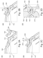
Fig. 2A shows - in a cross section view - a section of theconnector housing 102 and a section of themate assist device 150 of theelectrical connector system 100 according to an embodiment of the present disclosure. The position of theconnector housing 102 and themate assist device 150 relative to each other corresponds to an unmated state of theconnector housing 102 with the corresponding counter connector housing (not shown). In the unmated state, the plurality ofteeth 110 and the plurality ofteeth 156 are not engaged with each other. Furthermore,Fig. 2A shows the lockinglatch 108 and theportion 112 of the lockinglatch 108 which are described in the context ofFig. 1A . For simplicity, these two portions are not referenced again inFigs. 2B and 2C . -
Fig. 2B shows - in a cross section view - a section of theconnector housing 102 and a section of themate assist device 150 of theelectrical connector system 100 according to an embodiment of the present disclosure. The position of theconnector housing 102 and themate assist device 150 relative to each other corresponds to a mated state of the connector housing and the corresponding counter connector housing (not shown). In the mated state, the plurality ofteeth 110 of theconnector housing 102 and the plurality ofteeth 156 of themate assist device 150 are engaged with each other. This means that relative movement of themate assist device 150 relative to theconnector housing 102 is blocked. Hence, the position of theconnector housing 102 and themate assist device 150 relative to each other may be referred to as a locking position of the electrical connector systems. The skilled person recognizes that the two pluralities ofteeth Fig. 2B is a position defined solely by design of components of theelectrical connector system 100 and is marked by a dashedline 200. In other words, the locking position indicated by theline 200 corresponds to the theoretical case in which manufacturing tolerances are neglected. Furthermore, as generally known to the skilled person, when the first plurality ofteeth 110 and the second plurality ofteeth 156 are engaged with each other, the saw-tooth geometry allows their relative movement with each other in only one direction and may be regarded as offering a ratchet-like functionality. -
Fig. 2C shows - in a cross section view - a section of theconnector housing 102 and a section of themate assist device 150 of theelectrical connector system 100 according to an embodiment of the present disclosure. The position of theconnector housing 102 and themate assist device 150 relative to each other correspond to the mated state. However, unlike inFig. 2B , inFig. 2C manufacturing tolerances are considered. This results in the locking position of the plurality ofteeth 110 and the plurality ofteeth 156 being shifted from the theoretical case indicated by theline 200 to the left-hand side (counterclockwise). The actual locking position is marked by a dashedline 202 and its deviation from theoretical case is indicated by two curved arrows pointing respectively to thelines line 202 corresponds to the mated state in which manufacturing tolerances are compensated due to displacement of themate assist device 150 anticlockwise beyond theline 200. This displacement results in enhanced quality of electrical contact between respective electrical contact elements (for holding of which theconnector housing 102 and the corresponding counter connector housing are adapted). Due to integration of the locking means (the first plurality ofteeth 110 and the second plurality of teeth 156) with theconnector housing 102 and themate assist device 150 no additional burden for the user of theelectrical connector system 100 arises - beyond the usual mating of theconnector housing 102 with themate assist device 150. -
Fig. 2D shows - in a cross section view - a section of theconnector housing 102, a section of themate assist device 150 and a section of the correspondingcounter connector housing 204 of theelectrical connector system 100 according to an embodiment of the present disclosure. Further, one of thegear elements 154 of themate assist device 150 andcorresponding gear elements 206 of thecounter connector housing 204 are shown. The displacement between thelines Fig. 2C results in an angular displacement of themate assist device 150 in a counterclockwise direction which leads to a force acting upon thegear elements 206 as indicated by anarrow 208. This force results in tightening of the mating state of theconnector housing 102 and thecounter connector housing 204 along their mating direction indicated by anarrow 210. -
Fig. 3A shows schematically an initial phase of an unlocking process of theconnector housing 102 and themate assist device 150 of theelectrical connector system 100 according to an embodiment of the present disclosure. Prior to the initial phase of the unlocking process, theconnector housing 102 and their mate assistdevice 150 are in the mated state; the first plurality ofteeth 110 and the second plurality ofteeth 156 are engaged with each other in their locking position. Anarrow 300 indicates a direction of a force to be exerted upon theportion 112 of the lockinglatch 108 in order to unlock the locking means (i.e., to effectuate disengagement of the first plurality ofteeth 110 and the second plurality ofteeth 156 from each other). This direction is essentially parallel to teeth flanks carrying engaging forces between the first plurality ofteeth 110 and the second plurality ofteeth 156. -
Fig. 3B shows schematically a further phase of an unlocking process of theconnector housing 102 and themate assist device 150 of theelectrical connector system 100 according to an embodiment of the present disclosure. Pressing theportion 112 of the lockinglatch 108 in the direction explained inFig. 3A results in disengagement of the first plurality ofteeth 110 and the second plurality ofteeth 156 from each other. Thereupon, rotating themate assist device 150 clockwise - as indicated by an arrow 302 - transitions theelectrical connector system 100 to its unmated state. -
Fig. 4A shows - in a three-dimensional view - anelectrical connector system 400 comprising afirst connector housing 402 and asecond connector housing 404. Theelectrical connector system 400 further comprises an unlockingarm 406 which is accessible and adapted to be operable (e.g., by the user) to facilitate unlocking the electrical connector system as explained in conjunction withFig. 4B below. Unlike theelectrical connector system 100 explained in the context ofFigs. 1A, 1B ,2A, 2B ,2C, 2D ,3A and 3B , theelectrical connector system 400 is not equipped with any mate assist. -
Fig. 4B shows - in a cross section view - a section of theelectrical connector system 400. Thefirst connector housing 402 comprises aninterface member 408 adapted to (e.g., in a mated state of the electrical connector system 400) penetrate thesecond connector housing 404. Thefirst connector housing 402 further comprises a first plurality ofteeth 410 formed on theinterface member 408. Thesecond connector housing 404 comprises a lockingtongue member 412 having a second plurality ofteeth 414 formed thereon. The first plurality ofteeth 410 and the second plurality ofteeth 414 compose an embodiment of locking means of the present disclosure. In the mated state of the electrical connector system 400 (as shown inFig. 4B ), the first plurality ofteeth 410 and the second plurality ofteeth 414 are engaged with each other. Hence, the position of thefirst connector housing 402 and thesecond connector housing 404 relative to each other may be referred to as a locking position of theelectrical connector system 400. The skilled person recognizes that the two pluralities ofteeth electric connector 100. The unlockingarm 406 is arranged such that, when the unlocking arm is operated (e.g., by the user), the unlocking arm exerts a force upon theinterface member 408 resulting in disengagement of the first plurality ofteeth 410 and the second plurality ofteeth 414 from each other and thereby enables transition of theelectrical connector system 400 to its unmated state.
Claims (15)
- An electrical connector system comprising:a. a connector housing adapted for holding one or more electrical contact elements,b. a mate assist device associated with the connector housing, andc. locking means for locking the mate assist device relative to the connector housing;characterized in thatd. the locking means comprise a first plurality of teeth associated with the connector housing and a second plurality of teeth associated with the mate assist device;e. wherein the first plurality of teeth and the second plurality of teeth are adapted to be engaged with each other and thereby to enable different locking positions of the mate assist device relative to the connector housing in a mated state of the connector housing with a corresponding counter connector housing.
- An electrical connector system comprising:a. a first connector housing adapted for holding one or more electrical contact elements and a corresponding second connector housing adapted for holding one or more electrical contact elements, andb. locking means for locking the two housings with each other;characterized in thatc. the locking means comprise a first plurality of teeth associated with the first connector housing and a second plurality of teeth associated with the corresponding second connector housing;d. wherein the first plurality of teeth and the second plurality of teeth are adapted to be engaged with each and thereby to enable different locking positions of the first connector housing relative to the corresponding second connector housing in a mated state of the electrical connector system.
- The electrical connector system of claim 1 or 2, wherein each of the first plurality of teeth and the second plurality of teeth comprise a saw-tooth geometry.
- The electrical connector system of any one of the preceding claims, wherein the first plurality of teeth and the second plurality of teeth are each respectively arranged in a tooth rack.
- The electrical connector system of any one of the preceding claims, wherein the first plurality of teeth and the second plurality of teeth are adapted to allow relative movement with each other in only one direction, when engaged.
- The electrical connector system of claim 1, wherein the connector housing comprises a locking latch for locking the mate assist device in the mated state, and wherein the first plurality of teeth is provided on the locking latch.
- The electrical connector system of claim 2, wherein the electrical connector system further comprises an unlocking arm, wherein the unlocking arm is accessible when the two housings are in the mated state, and wherein the unlocking arm is arranged such that, when the unlocking arm is operated, the unlocking arm disengages the first and second plurality of teeth.
- The electrical connector system of claim 1, wherein the mate assist device comprises a lever and wherein the second plurality of teeth is provided on the lever.
- The electrical connector system of claim 1, wherein the mate assist device comprises a slider and wherein the second plurality of teeth is provided on the slider.
- The electrical connector system of claim 1, wherein the mate assist device comprises a cam-lever system and wherein the second plurality of teeth is provided on a cam of the cam-lever system.
- The electrical connector system of any of the preceding claims, wherein the first and second plurality of teeth each comprises at least two teeth, preferably at least three teeth, at least four teeth, or a at least five teeth.
- The electrical connector system of any of claims 1 to 10, wherein a number of the first plurality of teeth and a number of the second plurality of teeth are different.
- The electrical connector system of any of the preceding claims, wherein the different locking positions are at least two locking positions, preferably at least three locking positions, at least four locking positions, or at least five locking positions.
- The electrical connector system of any of the preceding claims, wherein the different locking positions are arranged to provide compensation of manufacturing tolerances of components of the electrical connector system.
- The electrical connector system of any of claim 1, wherein the electrical connector system further comprises the corresponding counter connector housing.
Priority Applications (1)
| Application Number | Priority Date | Filing Date | Title |
|---|---|---|---|
| EP23206989.8A EP4550587A1 (en) | 2023-10-31 | 2023-10-31 | Serration feature based clearance compensation mechanism for an electrical connector |
Applications Claiming Priority (1)
| Application Number | Priority Date | Filing Date | Title |
|---|---|---|---|
| EP23206989.8A EP4550587A1 (en) | 2023-10-31 | 2023-10-31 | Serration feature based clearance compensation mechanism for an electrical connector |
Publications (1)
| Publication Number | Publication Date |
|---|---|
| EP4550587A1 true EP4550587A1 (en) | 2025-05-07 |
Family
ID=88600918
Family Applications (1)
| Application Number | Title | Priority Date | Filing Date |
|---|---|---|---|
| EP23206989.8A Pending EP4550587A1 (en) | 2023-10-31 | 2023-10-31 | Serration feature based clearance compensation mechanism for an electrical connector |
Country Status (1)
| Country | Link |
|---|---|
| EP (1) | EP4550587A1 (en) |
Citations (6)
| Publication number | Priority date | Publication date | Assignee | Title |
|---|---|---|---|---|
| KR20150047985A (en) * | 2013-10-25 | 2015-05-06 | 현대모비스 주식회사 | Connector assembly |
| EP3171462A1 (en) * | 2015-11-23 | 2017-05-24 | TE Connectivity Germany GmbH | Electric connector with secondary locking member and electric connector assembly |
| EP3361580A1 (en) * | 2017-02-08 | 2018-08-15 | Delphi Technologies LLC | Electrical connector assembly with connection assist |
| CN115149345A (en) * | 2022-08-01 | 2022-10-04 | 高创(苏州)电子有限公司 | Interface and electronic equipment having the same |
| US20220376435A1 (en) * | 2021-05-18 | 2022-11-24 | Te Connectivity Germany Gmbh | Plug Connector and Connector Set with a Lever Extension |
| CN115528489A (en) * | 2022-04-11 | 2022-12-27 | 钟世煜 | FPC connector |
-
2023
- 2023-10-31 EP EP23206989.8A patent/EP4550587A1/en active Pending
Patent Citations (6)
| Publication number | Priority date | Publication date | Assignee | Title |
|---|---|---|---|---|
| KR20150047985A (en) * | 2013-10-25 | 2015-05-06 | 현대모비스 주식회사 | Connector assembly |
| EP3171462A1 (en) * | 2015-11-23 | 2017-05-24 | TE Connectivity Germany GmbH | Electric connector with secondary locking member and electric connector assembly |
| EP3361580A1 (en) * | 2017-02-08 | 2018-08-15 | Delphi Technologies LLC | Electrical connector assembly with connection assist |
| US20220376435A1 (en) * | 2021-05-18 | 2022-11-24 | Te Connectivity Germany Gmbh | Plug Connector and Connector Set with a Lever Extension |
| CN115528489A (en) * | 2022-04-11 | 2022-12-27 | 钟世煜 | FPC connector |
| CN115149345A (en) * | 2022-08-01 | 2022-10-04 | 高创(苏州)电子有限公司 | Interface and electronic equipment having the same |
Similar Documents
| Publication | Publication Date | Title |
|---|---|---|
| EP2274800B1 (en) | Lever type electrical connector | |
| EP1859513B2 (en) | Lever mated connector assembly with a position assurance device | |
| CN103490228B (en) | Comprise the electric connection system of coupling auxiliary lever | |
| US7255580B2 (en) | Electrical connector and electrical connector assembly having lever assist with latch hold down mechanism | |
| US8419462B2 (en) | Lever type connector | |
| EP3058625B1 (en) | Connector assembly with integrated lever locking system | |
| EP2889966B1 (en) | Lever-actuated electrical connector | |
| US10511125B2 (en) | Connector having a lever | |
| EP2863490B1 (en) | Connector assembly with CPA member | |
| CN101981763B (en) | Lever type connector | |
| EP3322041B1 (en) | Connector assembly with integrated lever locking system | |
| EP2059979B1 (en) | Lever type electrical connector | |
| US20110130026A1 (en) | Lever-type connector | |
| EP3886266B1 (en) | Electrical connector with a mate assist system | |
| JP2016537778A (en) | Dual moving mating auxiliary connector | |
| US6224414B1 (en) | Half-fitting prevention connector | |
| JP5707256B2 (en) | Lever type connector | |
| JPH09219253A (en) | Electrical connector | |
| JP2587276Y2 (en) | Lever drive type connector | |
| WO2025140953A1 (en) | An electrical connector assembly | |
| US20260045738A1 (en) | Lever-equipped connector, connector assembly and assembly method | |
| JP2019139839A (en) | Connector member and connector | |
| EP4726936A1 (en) | Right-angle electrical connector with a mate assist system | |
| JP7758795B2 (en) | Connector housing assemblies, connectors, and connection assemblies | |
| EP4697524A1 (en) | Electrical connector assembly and its method of assembly |
Legal Events
| Date | Code | Title | Description |
|---|---|---|---|
| PUAI | Public reference made under article 153(3) epc to a published international application that has entered the european phase |
Free format text: ORIGINAL CODE: 0009012 |
|
| STAA | Information on the status of an ep patent application or granted ep patent |
Free format text: STATUS: THE APPLICATION HAS BEEN PUBLISHED |
|
| AK | Designated contracting states |
Kind code of ref document: A1 Designated state(s): AL AT BE BG CH CY CZ DE DK EE ES FI FR GB GR HR HU IE IS IT LI LT LU LV MC ME MK MT NL NO PL PT RO RS SE SI SK SM TR |
|
| STAA | Information on the status of an ep patent application or granted ep patent |
Free format text: STATUS: REQUEST FOR EXAMINATION WAS MADE |
|
| 17P | Request for examination filed |
Effective date: 20251106 |