EP4550585A1 - Electrical connector assembly - Google Patents
Electrical connector assembly Download PDFInfo
- Publication number
- EP4550585A1 EP4550585A1 EP23206710.8A EP23206710A EP4550585A1 EP 4550585 A1 EP4550585 A1 EP 4550585A1 EP 23206710 A EP23206710 A EP 23206710A EP 4550585 A1 EP4550585 A1 EP 4550585A1
- Authority
- EP
- European Patent Office
- Prior art keywords
- electrical
- tpa
- actuating member
- connector housing
- connector assembly
- Prior art date
- Legal status (The legal status is an assumption and is not a legal conclusion. Google has not performed a legal analysis and makes no representation as to the accuracy of the status listed.)
- Pending
Links
Images


Classifications
-
- H—ELECTRICITY
- H01—ELECTRIC ELEMENTS
- H01R—ELECTRICALLY-CONDUCTIVE CONNECTIONS; STRUCTURAL ASSOCIATIONS OF A PLURALITY OF MUTUALLY-INSULATED ELECTRICAL CONNECTING ELEMENTS; COUPLING DEVICES; CURRENT COLLECTORS
- H01R13/00—Details of coupling devices of the kinds covered by groups H01R12/70 or H01R24/00 - H01R33/00
- H01R13/40—Securing contact members in or to a base or case; Insulating of contact members
- H01R13/42—Securing in a demountable manner
- H01R13/436—Securing a plurality of contact members by one locking piece or operation
- H01R13/4367—Insertion of locking piece from the rear
- H01R13/4368—Insertion of locking piece from the rear comprising a temporary and a final locking position
-
- H—ELECTRICITY
- H01—ELECTRIC ELEMENTS
- H01R—ELECTRICALLY-CONDUCTIVE CONNECTIONS; STRUCTURAL ASSOCIATIONS OF A PLURALITY OF MUTUALLY-INSULATED ELECTRICAL CONNECTING ELEMENTS; COUPLING DEVICES; CURRENT COLLECTORS
- H01R13/00—Details of coupling devices of the kinds covered by groups H01R12/70 or H01R24/00 - H01R33/00
- H01R13/40—Securing contact members in or to a base or case; Insulating of contact members
- H01R13/42—Securing in a demountable manner
- H01R13/426—Securing by a separate resilient retaining piece supported by base or case, e.g. collar or metal contact-retention clip
-
- H—ELECTRICITY
- H01—ELECTRIC ELEMENTS
- H01R—ELECTRICALLY-CONDUCTIVE CONNECTIONS; STRUCTURAL ASSOCIATIONS OF A PLURALITY OF MUTUALLY-INSULATED ELECTRICAL CONNECTING ELEMENTS; COUPLING DEVICES; CURRENT COLLECTORS
- H01R13/00—Details of coupling devices of the kinds covered by groups H01R12/70 or H01R24/00 - H01R33/00
- H01R13/40—Securing contact members in or to a base or case; Insulating of contact members
- H01R13/42—Securing in a demountable manner
- H01R13/436—Securing a plurality of contact members by one locking piece or operation
- H01R13/4361—Insertion of locking piece perpendicular to direction of contact insertion
- H01R13/4362—Insertion of locking piece perpendicular to direction of contact insertion comprising a temporary and a final locking position
-
- H—ELECTRICITY
- H01—ELECTRIC ELEMENTS
- H01R—ELECTRICALLY-CONDUCTIVE CONNECTIONS; STRUCTURAL ASSOCIATIONS OF A PLURALITY OF MUTUALLY-INSULATED ELECTRICAL CONNECTING ELEMENTS; COUPLING DEVICES; CURRENT COLLECTORS
- H01R13/00—Details of coupling devices of the kinds covered by groups H01R12/70 or H01R24/00 - H01R33/00
- H01R13/46—Bases; Cases
- H01R13/502—Bases; Cases composed of different pieces
- H01R13/506—Bases; Cases composed of different pieces assembled by snap action of the parts
-
- H—ELECTRICITY
- H01—ELECTRIC ELEMENTS
- H01R—ELECTRICALLY-CONDUCTIVE CONNECTIONS; STRUCTURAL ASSOCIATIONS OF A PLURALITY OF MUTUALLY-INSULATED ELECTRICAL CONNECTING ELEMENTS; COUPLING DEVICES; CURRENT COLLECTORS
- H01R13/00—Details of coupling devices of the kinds covered by groups H01R12/70 or H01R24/00 - H01R33/00
- H01R13/64—Means for preventing incorrect coupling
-
- H—ELECTRICITY
- H01—ELECTRIC ELEMENTS
- H01R—ELECTRICALLY-CONDUCTIVE CONNECTIONS; STRUCTURAL ASSOCIATIONS OF A PLURALITY OF MUTUALLY-INSULATED ELECTRICAL CONNECTING ELEMENTS; COUPLING DEVICES; CURRENT COLLECTORS
- H01R43/00—Apparatus or processes specially adapted for manufacturing, assembling, maintaining, or repairing of line connectors or current collectors or for joining electric conductors
- H01R43/20—Apparatus or processes specially adapted for manufacturing, assembling, maintaining, or repairing of line connectors or current collectors or for joining electric conductors for assembling or disassembling contact members with insulating base, case or sleeve
Definitions
- the present invention relates to an electrical connector assembly with a terminal position assurance (TPA) member, as well as to a method for assembling a connector assembly.
- TPA terminal position assurance
- Electrical connectors and electrical connector assemblies are commonly used to connect various cables, such as for example telecommunication cables, common networking cables, signaling cables or in general any electrical wiring.
- electrical connectors are particularly used for joining electrical circuits, wherein a male ended plug of an electrical connector may be adapted to be connected to a respective female ended jack of a corresponding counter connector.
- TPA terminal position assurance
- a TPA device or additionally or alternatively referred to as TPA member is often utilized for electrical connectors to detect incomplete insertion of contact terminals into a connector housing. They also assist in assuring that the contact terminals are properly positioned in the respective housing.
- a TPA member may thereby be mounted movably to the connector housing and may secure the terminal within the connector housing when being fully inserted.
- TPA devices that are external parts and that need to be assembled after electrical terminals are in position of the connector to fix the positioning thereof.
- Such external TPA devices have several disadvantages. For instance, accessibility of these TPA devices is not optimal. Moreover, keeping a water tightness of the connector may become difficult and the assembly steps are usually complex, as a plurality of different parts are necessary to be assembled.
- an object of the present invention to provide an electrical connector assembly which overcomes the above outlined disadvantages at least partially. It is in particular an object of the present invention to provide an electrical connector assembly having a TPA functionality, whereby the TPA function can be provided with improved accessibility for the user, with an improved water tightness and by reducing the number of assembly steps of the user. Overall, the TPA functionality should be easy to be performed by a user without requiring much effort or personnel.
- An aspect of the invention relates to an electrical connector assembly comprising: a connector housing adapted to receive one or more electrical terminals; a terminal position assurance, TPA, member adapted to be mounted to the connector housing and being movable relative to the connector housing between a pre lock position and a final-lock position when mounted; an actuating member adapted to be mounted to the connector housing and being movable relative to the connector housing between a first position and a second position when mounted, wherein the movement between first and second position is essentially parallel to the receiving direction of the one or more electrical terminals; wherein when moving from the first position to the second position the actuating member is adapted to move the TPA member from the pre-lock position to the final-lock position.
- TPA terminal position assurance
- the connector housing may thereby comprise at least one aperture which is adapted to receive the one or more electrical terminals or also termed one or more contact terminals therein.
- the housing may form the main housing of the connector and may in general have any shape adapted to be connected to a corresponding counter connector. It is not precluded according to the present disclosure that the connector housing also include means for locking the housing to the corresponding counter connector.
- the electrical connector assembly further comprises a terminal position assurance, TPA, member which is adapted to be mounted to the connector housing and which is movable relative to the connector housing between a pre-lock position and a final-lock position when the TPA member is in a mounted condition with the connector housing.
- TPA terminal position assurance
- the TPA member is typically pre-mounted to the connector housing.
- the TPA member may thereby provide TPA functionality to the electrical connector assembly. This may mean that it facilitates securing and/or locking the positioning of the one or more electrical terminals within the connector housing when the TPA member is in the final-lock position.
- the TPA member When the TPA member is in the pre-lock position, the TPA member may facilitate insertion or removal of the one or more electrical terminals.
- the locking function of the TPA member for the one or more electrical terminals can be set and unset.
- the movement of the TPA member between the pre-lock and final-lock position is a linear movement with respect to its direction. However, it is not precluded that the movement is non-linear.
- the direction of movement of the TPA member may be along a lateral direction relative to the connector housing. The skilled person may be aware of determining the lateral direction when looking at the connector housing.
- the electrical connector assembly further comprises an actuating member which is adapted to be mounted to the connector housing and which is movable relative to the connector housing between a first position and a second position when the actuating member is in a mounted condition.
- the actuating member may on one example only move between the first position and second position in mounted condition. As understood, a plurality of different position between the first and the second position may be possible.
- the movement of the actuating member between the first and second position is a linear movement with respect to its direction. However, it is not precluded that the movement of the actuating member between the first and second position is non-linear.
- the movement of the actuating member between the first and the second position is essentially parallel to the receiving direction of the one or more electrical terminals.
- the receiving direction may be substantially parallel to and/or the same as a longitudinal direction, such as a longitudinal direction of the one or more electrical terminals.
- the receiving direction may be substantially parallel to and/or the same as a mating direction.
- the mating direction may be understood as the direction in which the connector housing is mated with another connector part, e.g., from a side opposite to a side at which the electrical terminals are received.
- the actuating member may be a sliding element or a slider, which is configured to be guided along the one or more electrical terminals, as described elsewhere herein in greater detail.
- the actuating member is adapted to move the TPA member from the pre-lock position to the final-lock position, when the actuating member is moving from the first position to the second position.
- the TPA member may advantageously be moved indirectly between the pre-lock position and the final-lock position.
- the movement of the TPA member may be triggered by the movement of the actuating member. This simplifies the locking of the one or more electrical terminals.
- the present disclosure provides an improved electrical connector assembly and in particular an improved TPA functionality.
- the TPA member may be able to be mounted to the connector housing already before the one or more electrical terminals are inserted.
- a harness maker and/or OEM may easily move the TPA member inside the connector housing without having to remove and/or assemble the connector housing.
- This provides the advantage that sealing of the overall electrical connector assembly, such as a water tightness of the overall electrical connector assembly can be improved. This is for instance advantageous when considered prior art TPA members, which are assembled after electrical terminals are inserted into the connector housing.
- the movement of the actuating member between first position and second position being essentially parallel to the receiving direction of the one or more electrical terminals may allow for the advantages mentioned in here.
- the TPMA member has the advantage that it can be indirectly and easily accessed. Further, it may allow to use different sizes of electrical terminals.
- different types of electrical terminals may be employed, for instance, electrical terminals provided by stamping, machining, cold forming, just to name a few in a non-exhaustive list of examples.
- the TPA member, the connector housing and/or the actuating member may be of any kind of suitable material.
- the TPA member, the connector housing and/or the actuating member may be made of a polymer and may preferably be injection-molded polymer components.
- the TPA member is pre-mounted to the connector housing, before the one or more terminals are received within the connector housing. Pre-mounting may not be possible for conventional prior art TPA members, which are typically provided as external parts as understood by the skilled person.
- the pre-mounted TPA member facilitates assembling of the respective parts and makes it easier to maintain a needed sealing functionality of the electrical connector assembly.
- the connector housing comprises one or more fixing elements and/or recesses arranged to engage with corresponding recesses and/or fixing elements of the one or more terminals, respectively.
- the connector housing comprises one or more fixing elements arranged to engage with corresponding recesses of the one or more terminals.
- the connector housing comprises one or more recesses that are arranged to engage with corresponding fixing elements of the one or more terminals.
- Fixing elements may be implemented in various way including but not limited to protrusions, extending portions, snap elements, or the like.
- the TPA member comprises at least one projection and the actuating member comprises at least one tapered surface shaped in correspondence to the projection for engaging with the projection when the actuating member is moving between the first position and the second position.
- the tapered surface may also be understood as a cut-out made in a material of the actuating member and or a recess provided in the actuating member. Accordingly, the projection and the tapered surface are interacting with each other, to facilitate that the TPA member is moved when the actuating member is being moved from the first position to the second position.
- the projection comprises a cam surface configured to engage with the tapered surface of the actuating member, wherein the surfaces are inclined with respect to the movement between first and second position.
- a cam surface may be understood as a specially shaped surface on a moving, contacting, rotating and/or sliding component.
- the cam surface may be designed to interact with another component.
- the tapered surface may be the part that imparts the motion to the cam surface, such may be a cam follower in the present disclosure.
- the cam surface may have any suitable shape to allow for transmitting a movement. Further, the cam surface may be designed in such a manner that mechanical integrity, durability and robustness is improved.
- Various types of cam surfaces are encompassed in the present disclosure including but not limited to one or more of the following: a uniform motion cam surface, which may be designed to produce uniform motion, meaning the moved part moves at a constant velocity as it contacts the moving part.
- a harmonic motion cam surface such that motion is imported in a substantially sinusoidal or oscillatory manner.
- a dwell cam surface such that at some point of movement of the actuating member, there is no motion of the TPA member, allowing the TPA member to remain stationary for a period before moving again.
- Further examples are pear cam surfaces, heart cam surface, cylindrical cam surfaces, or the like.
- the respective surfaces are inclined with respect to the movement between the first and the second position.
- the angle of inclination may influence the movement of the TPA member.
- a large angle e.g., greater than 45°, greater than 50°, or greater than 60°
- the angle of inclination may be small (e.g., less than 45°, less than 30°, or less than 20°) to allow to finetune movement of the TPA member.
- the projection of the TPA member projects in a direction substantially parallel to the receiving direction of the one or more electrical terminals. This facilitates that upon movement of the actuating member along said receiving direction, the TPA member may be moved from the pre-lock position to the final-lock position.
- the projection of the TPA member may extend substantially perpendicular from a plate portion of the TPA member as described elsewhere herein in greater detail.
- the projection of the TPA member is sliding along the tapered surface of the actuating member when the actuating member is moving between the first position and the second position. This allows for a direct engagement of the actuating member on the TPA member. Sliding may be understood as contacting or touching.
- the main direction of the tapered surface and the projection is angled relative to the movement direction of the actuating member.
- the movement direction of the TPA member may thereby be defined by the movement of the actuating member between the first and second position.
- the movement direction of the TPA member between the pre-lock position and the final-lock position may thereby be accurately influenced by the shape of the projection and the tapered surface.
- the TPA member may be a lateral TPA member, which performs a lateral movement relative to the receiving direction of the electrical terminals, when the movement direction of the actuating member is parallel to the receiving direction.
- the TPA member comprises a locking portion arranged to engage with the one or more electrical terminals in the final-lock position for substantially fixing the one or more electrical terminals. This may facilitate locking of the one or more electrical terminals once the TPA member is brought from the pre-lock position to the final-lock position.
- the actuating member comprises one or more openings shaped in correspondence to the one or more electrical terminals such that the movement of the actuating member between first and second position is essentially parallel to the receiving direction of the one or more electrical terminals.
- the openings facilitate that the one or more electrical terminals can be easily moved along the receiving direction without much effort for the user. Thereby, the movement between the first and second position is substantially predetermined. This provides for a substantially fail-safe movement, which is appreciated by the user.
- the openings may adopt any suitable shape. They may be shaped such that the actuating member is not touching the one or more electrical terminals upon movement. However, touching is not precluded in the present disclosure and in some instance, it is specifically desired.
- the actuating member comprises one or more guiding rails arranged along the receiving direction of the one or more electrical terminals to engage with one or more correspondingly shaped guiding protrusions arranged at an inner periphery of the connector housing.
- the guiding rails allow that the movement of the actuating member is further defined by way of its geometrical shape. This further contributes to a fail-safe arrangement and a simplified construction.
- the actuating member may comprise guiding protrusions and the inner periphery of the connector housing may comprise one or more guiding rails arranged along the receiving direction of the one or more electrical terminals.
- the actuating member comprises one or more snap elements arranged to engage with one or more apertures arranged at an inner periphery of the connector housing, wherein the snap elements are preferably arranged at an end of the actuating member in the receiving direction that abuts with the TPA member in the second position.
- the snap elements may comprise latches, noses, clips, or the like.
- the TPA member comprises at least one sliding means for sliding between the pre-lock position and the final-lock position and at least one fixing means for fixing the TPA member to the connector housing in the final-lock position.
- the sliding means enable that the TPA member may be provided in a pre-mounted state before receiving the one or more electrical terminals.
- the TPA member comprises a plate portion that extends in a plane perpendicular to the receiving direction of the one or more terminals, the plate portion comprising one or more openings adapted to receive the one or more electrical terminals, wherein the openings preferably have inner contours adapted to interact with a locking contour of the one or more electrical terminals for substantially fixing the one or more electrical terminals.
- the fixing may be releasably in some instances, if desired.
- a plate portion may be, for instance, different than a U-shaped form or the like.
- the plate portion may be substantially planar and rectangular.
- the plate portion may be substantially flat.
- the plate portion comprises one or more openings, nevertheless, the shape of the TPA member may still be regarded as being substantially planar and/or rectangular. Same applies to the at least one projection of the TPA member.
- the plate portion may thereby provide the TPA functionality.
- the inner contours may comprise a locking portion of the TPA member as described elsewhere herein.
- the inner contours may be provided with a ticker material or a material which possesses a greater strength. This facilitates locking of the one or more electrical terminals by way of the TPA member.
- the movement of the actuating member between the first and second position is perpendicular to the movement of the TPA member between the pre-locked and the locked position.
- the assembly comprises plurality of electrical terminals, wherein the TPA member comprises a plurality of openings through which the plurality of electrical terminals extends, wherein the actuating member comprises a plurality of openings through which the plurality of electrical terminals extends, wherein the openings of the TPA member are substantially aligned with openings of actuating member.
- the opening of the TPA member of this embodiment correspond to the openings of the plate portion.
- the openings of the TPA member are not circular. This has the advantage that once the terminals are received in the openings of the TPA member, said member can be moved in a lateral direction (referred to as LD in the figures) to provide for locking in the final-lock position.
- Shapes that are not circular may include one or more of the following: triangles, squares, rectangles, pentagons, hexagons, heptagons, octagons, nonagons, decagons, ellipses, parallelograms, trapezoids, rhombi, kites, stars, hearts, crescents, arrowheads, crosses, and diamonds.
- the assembly is further comprising one or more terminals and a cover adapted to be mounted to the connector housing, thereby covering an outer periphery of the connector housing at least partially, wherein the cover preferably comprises one or more openings for guiding the one or more electrical terminals therethrough, wherein, the actuating member is preferably sandwiched between the TPA member and the cover when mounted.
- the cover may also be adapted to cover interior parts of the connector housing at least partially in a mounted condition.
- the cover may be a separate part distinct from the actuating member and has a separate and additional function compared to the actuating member.
- the cover may allow for protection against external impacts, such as dirt, dust, moisture, vibration, or the like. This may be the case, as it covers the connector housing and, thereby, the TPA member in its final-lock position. Further, the cover may also comprise openings, shaped similarly as the openings of the actuating member. This may facilitate that the one or more electrical terminals can also be guided through the cover.
- the cover may comprise or may be made of a polymer.
- a further aspect is related to a method for assembling a connector assembly as described elsewhere herein.
- the method comprises: mounting the TPA member to the connector housing; assembling one or more terminals to the connector housing; and moving, preferably by hand, the actuating member from the first position to the second position, so that the TPA member is moved from the pre-lock position to the final-lock position.
- the method comprises all advantages of the electrical connector assembly described herein. Particularly, it is noted that the method as described herein may include all aspects and/or embodiments described herein, even if not expressly described as a method but rather with reference to the electrical connector assembly. It is also to be understood that the features and advantages described with reference to the electrical connector assembly may equally be applicable to the method as described herein.
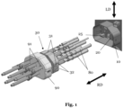
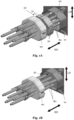
- Figs. 1 , 1A, and 1B illustrates an electrical connector assembly 1 according to an embodiment of the present invention in three different assembly steps.
- Fig. 1 shows a step in which the terminals 80 are not received in the housing 10.
- Fig. 1A shows a step in which the terminals 80 are received in the housing 10 and the actuating member 30 is ready to be moved to the second position.
- Fig. 1B shows a step in which the actuating member 30 is moved into the second position and the TPA member 20 is in the final-lock position.
- the assembly 1 comprises a connector housing 10 that can receive terminals 80 (five of which are depicted), a TPA member 20 that is already pre-mounted to the connector housing 20 and that may be in a pre-lock position, and an actuating member 30, which can be a slider. As appreciated, the TPA member 20 is pre-mounted to the housing 20 before the terminals 80 are received.
- the actuating member 30 comprises one or more openings 34 shaped in correspondence to the one or more electrical terminals 80 such that the movement of the actuating member 30 between first and second position is essentially parallel to the receiving direction RD of the one or more electrical terminals 80.
- the assembly 1 comprises plurality of electrical terminals 80, wherein the TPA member 20 comprises a plurality of openings 27 through which the plurality of electrical terminals 80 extends, wherein the actuating member 30 comprises a plurality of openings 34 through which the plurality of electrical terminals 80 extends, wherein the openings 27 of the TPA member 20 are substantially aligned with openings 34 of actuating member 30.
- the assembly 1 can also comprise a cover 90 adapted to be mounted to the connector housing 10, thereby covering an outer periphery of the connector housing 10 at least partially.
- the cover 90 can comprise one or more openings 91 for guiding the one or more electrical terminals 80 therethrough.
- the actuating member 30 can be sandwiched between the TPA member 20 and the cover 90 when mounted.
- the actuating member 30 comprises one or more snap elements 32 arranged to engage with one or more apertures arranged at an inner periphery of the connector housing 10.
- the snap elements 32 are preferably arranged at an end of the actuating member 30 in the receiving direction RD that abuts with the TPA member 20 in the second position.
- the actuating member is adapted for movement by hand between the first position and the second position.
- a user such as an operator can access and engage the mounted actuating member and move it between the first position and the second position without the need of much effort.
- the TPA member itself does not need to be accessed or engaged by hand of a user, as it is pre-mounted already in a position ready to be moved by the movement of the actuating member.
- the TPA member 20 can cover at least 40%, preferably at least 50%, more preferably at least 60%, more preferably at least 70%, more preferably at least 80% of the frontal area of the electrical connector housing.
- the frontal area may be substantially perpendicular to the receiving direction RD.
- the TPA member 20 may be designed as a small and compact component, as it does not need to be accessed by hand or any special tool. This may also pave the way for a more ergonomic operation of the TPA member 20. Further, the design of the TPA member 20 can be optimized to improve water tightness of the electrical connector assembly 1, to improve strength, and/or to improve robustness. This may be the case as the interaction between the TPA member 20 and the actuating member 30 can be well predicted in advance before bringing the TPA member 20 in the final-lock position by moving the actuating member 30 from the first position to the second position by moving and/or guiding the actuating member 30 essentially parallel to the receiving direction RD of the one or more electrical terminals 80.
- Figs. 2 and 2A illustrates the embodiment of the present invention of Fig. 1 in a cross-sectional view from a lateral side.
- Fig. 2 shows the embodiment in a pre-lock position.
- Fig. 2 shows the embodiment in a final-lock position.
- the connector housing 10 comprises one or more fixing elements 16 and/or recesses arranged to engage with corresponding recesses 81 and/or fixing elements of the one or more terminals 80, respectively.
- the TPA member 20 comprises at least one projection 25.
- the actuating member 30 comprises at least one tapered surface 33 shaped in correspondence to the projection 25 for engaging with the projection 25 when the actuating member 30 is moving between the first position and the second position.
- the TPA member comprises two projections 25.
- the actuating member 30 comprises two tapered surfaces 33.
- the projection 25 comprises a cam surface 26 configured to engage with the tapered surface 33 of the actuating member 30.
- the cam surface 26 and the tapered surface 33 are inclined with respect to the movement between first and second position of the actuating member 30.
- the projection 25 of the TPA member 20 projects in a direction substantially parallel to the receiving direction RD of the one or more electrical terminals 80.
- the projection 25 of the TPA member 20 is sliding along the tapered surface 33 of the actuating member 30 when the actuating member 30 is moving between the first position and the second position.
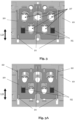
- Figs. 3 and 3A illustrates parts of an electrical connector assembly of an embodiment of the present invention in a frontal view.
- Fig. 3 shows the embodiment in a pre-lock position.
- Fig. 3A shows the embodiment in a final-lock position.
- the TPA member 20 comprises at least one sliding means 21 for sliding between the pre-lock position and the final-lock position and at least one fixing means 22 for fixing the TPA member 20 to the connector housing 10 in the final-lock position.
- Three sliding means 21 and two fixing means 22 are depicted.
- the TPA member 20 has the shape or comprises a plate portion that extends in a plane perpendicular to the receiving direction RD of the one or more terminals 80 (as also seen in Fig. 2 and Fig. 2A ), the plate portion comprises one or more openings 27 adapted to receive the one or more electrical terminals 80.
- the openings 27 can have inner contours adapted to interact with a locking contour of the one or more electrical terminals 80 for substantially fixing the one or more electrical terminals 80.
- the openings 27 of the TPA member 20 are not circular.
- Figs. 4 and 4A illustrates parts of an electrical connector assembly of an embodiment of the present invention in a perspective view ( Fig. 4 ) and in a frontal view ( Fig. 4A ).
- the actuating member 30 comprises one or more guiding rails 31 arranged along the receiving direction RD of the one or more electrical terminals 80 (as also indicated in Fig. 1 ) to engage with one or more correspondingly shaped guiding protrusions 11 arranged at an inner periphery of the connector housing 10.
- seal members may be provided to the connector housing 10 for sealing the assembly 1.
- the actuating member 30 when moving from the second position to the first position the actuating member 30 is adapted to move the TPA member 20 from the final-lock position to the pre-lock position. This may facilitate that the TPA member 20 could be brought into the pre-lock position in a fast and convenient manner.
Landscapes
- Engineering & Computer Science (AREA)
- Manufacturing & Machinery (AREA)
- Connector Housings Or Holding Contact Members (AREA)
- Details Of Connecting Devices For Male And Female Coupling (AREA)
Abstract
The present invention relates to an electrical connector assembly comprising: a connector housing (10) adapted to receive one or more electrical terminals (80); a terminal position assurance, TPA, member (20) adapted to be mounted to the connector housing (20) and being movable relative to the connector housing (20) between a pre lock position and a final-lock position when mounted; an actuating member (30) adapted to be mounted to the connector housing (20) and being movable relative to the connector housing (20) between a first position and a second position when mounted, wherein the movement between first and second position is essentially parallel to the receiving direction of the one or more electrical terminals; wherein when moving from the first position to the second position the actuating member (30) is adapted to move the TPA member (20) from the pre-lock position to the final-lock position.
Description
- The present invention relates to an electrical connector assembly with a terminal position assurance (TPA) member, as well as to a method for assembling a connector assembly.
- Electrical connectors and electrical connector assemblies are commonly used to connect various cables, such as for example telecommunication cables, common networking cables, signaling cables or in general any electrical wiring. In this context electrical connectors are particularly used for joining electrical circuits, wherein a male ended plug of an electrical connector may be adapted to be connected to a respective female ended jack of a corresponding counter connector.
- Many electrical connector assemblies are provided with a so-called terminal position assurance (TPA) feature, which allows for assuring that a terminal or contact is fully inserted into an electrical connector housing to form the electrical connector. To such an electrical connector, a corresponding connector may be mated from an end opposite to and end at which the terminal is inserted.
- A TPA device or additionally or alternatively referred to as TPA member is often utilized for electrical connectors to detect incomplete insertion of contact terminals into a connector housing. They also assist in assuring that the contact terminals are properly positioned in the respective housing. A TPA member may thereby be mounted movably to the connector housing and may secure the terminal within the connector housing when being fully inserted.
- Conventional electrical connectors typically employ TPA devices that are external parts and that need to be assembled after electrical terminals are in position of the connector to fix the positioning thereof. Such external TPA devices have several disadvantages. For instance, accessibility of these TPA devices is not optimal. Moreover, keeping a water tightness of the connector may become difficult and the assembly steps are usually complex, as a plurality of different parts are necessary to be assembled.
- It is thus an object of the present invention to provide an electrical connector assembly which overcomes the above outlined disadvantages at least partially. It is in particular an object of the present invention to provide an electrical connector assembly having a TPA functionality, whereby the TPA function can be provided with improved accessibility for the user, with an improved water tightness and by reducing the number of assembly steps of the user. Overall, the TPA functionality should be easy to be performed by a user without requiring much effort or personnel.
- The above-mentioned objects are at least partially achieved by the subject-matter of the independent claims. Preferred embodiments are subject of the dependent claims, and the skilled person finds hints for other suitable aspects of the present invention through the overall disclosure of the present application.
- An aspect of the invention relates to an electrical connector assembly comprising: a connector housing adapted to receive one or more electrical terminals; a terminal position assurance, TPA, member adapted to be mounted to the connector housing and being movable relative to the connector housing between a pre lock position and a final-lock position when mounted; an actuating member adapted to be mounted to the connector housing and being movable relative to the connector housing between a first position and a second position when mounted, wherein the movement between first and second position is essentially parallel to the receiving direction of the one or more electrical terminals; wherein when moving from the first position to the second position the actuating member is adapted to move the TPA member from the pre-lock position to the final-lock position.
- The connector housing may thereby comprise at least one aperture which is adapted to receive the one or more electrical terminals or also termed one or more contact terminals therein. The housing may form the main housing of the connector and may in general have any shape adapted to be connected to a corresponding counter connector. It is not precluded according to the present disclosure that the connector housing also include means for locking the housing to the corresponding counter connector.
- The electrical connector assembly further comprises a terminal position assurance, TPA, member which is adapted to be mounted to the connector housing and which is movable relative to the connector housing between a pre-lock position and a final-lock position when the TPA member is in a mounted condition with the connector housing. As described elsewhere herein, the TPA member is typically pre-mounted to the connector housing. The TPA member may thereby provide TPA functionality to the electrical connector assembly. This may mean that it facilitates securing and/or locking the positioning of the one or more electrical terminals within the connector housing when the TPA member is in the final-lock position. When the TPA member is in the pre-lock position, the TPA member may facilitate insertion or removal of the one or more electrical terminals. By moving the TPA member between the pre-lock position and the final-lock position, the locking function of the TPA member for the one or more electrical terminals can be set and unset. In one example, the movement of the TPA member between the pre-lock and final-lock position is a linear movement with respect to its direction. However, it is not precluded that the movement is non-linear. The direction of movement of the TPA member may be along a lateral direction relative to the connector housing. The skilled person may be aware of determining the lateral direction when looking at the connector housing.
- The electrical connector assembly further comprises an actuating member which is adapted to be mounted to the connector housing and which is movable relative to the connector housing between a first position and a second position when the actuating member is in a mounted condition. The actuating member may on one example only move between the first position and second position in mounted condition. As understood, a plurality of different position between the first and the second position may be possible. Preferably the movement of the actuating member between the first and second position is a linear movement with respect to its direction. However, it is not precluded that the movement of the actuating member between the first and second position is non-linear.
- The movement of the actuating member between the first and the second position is essentially parallel to the receiving direction of the one or more electrical terminals. The receiving direction may be substantially parallel to and/or the same as a longitudinal direction, such as a longitudinal direction of the one or more electrical terminals. The receiving direction may be substantially parallel to and/or the same as a mating direction. The mating direction may be understood as the direction in which the connector housing is mated with another connector part, e.g., from a side opposite to a side at which the electrical terminals are received. In one example, the actuating member may be a sliding element or a slider, which is configured to be guided along the one or more electrical terminals, as described elsewhere herein in greater detail.
- The actuating member is adapted to move the TPA member from the pre-lock position to the final-lock position, when the actuating member is moving from the first position to the second position. Thereby, merely by moving the actuating member form the first position to the second position, the TPA member may advantageously be moved indirectly between the pre-lock position and the final-lock position. Thereby, it may be understood that the movement of the TPA member may be triggered by the movement of the actuating member. This simplifies the locking of the one or more electrical terminals.
- In view of the foregoing, it is understood that when the TPA member is mounted to the connector housing, the movement thereof can be easily controlled by moving the actuating member, which is also mounted to the connector housing.
- In this manner, the present disclosure provides an improved electrical connector assembly and in particular an improved TPA functionality. In particular, the TPA member may be able to be mounted to the connector housing already before the one or more electrical terminals are inserted. Thus, for instance a harness maker and/or OEM may easily move the TPA member inside the connector housing without having to remove and/or assemble the connector housing. This provides the advantage that sealing of the overall electrical connector assembly, such as a water tightness of the overall electrical connector assembly can be improved. This is for instance advantageous when considered prior art TPA members, which are assembled after electrical terminals are inserted into the connector housing. Among other features, in particular the movement of the actuating member between first position and second position being essentially parallel to the receiving direction of the one or more electrical terminals may allow for the advantages mentioned in here. Furthermore, the TPMA member has the advantage that it can be indirectly and easily accessed. Further, it may allow to use different sizes of electrical terminals. In addition, different types of electrical terminals may be employed, for instance, electrical terminals provided by stamping, machining, cold forming, just to name a few in a non-exhaustive list of examples.
- The TPA member, the connector housing and/or the actuating member may be of any kind of suitable material. Preferably, the TPA member, the connector housing and/or the actuating member may be made of a polymer and may preferably be injection-molded polymer components.
- In a preferred embodiment of the electrical connector assembly as described in the present disclosure, the TPA member is pre-mounted to the connector housing, before the one or more terminals are received within the connector housing. Pre-mounting may not be possible for conventional prior art TPA members, which are typically provided as external parts as understood by the skilled person. The pre-mounted TPA member facilitates assembling of the respective parts and makes it easier to maintain a needed sealing functionality of the electrical connector assembly.
- In a preferred embodiment of the electrical connector assembly as described in the present disclosure, the connector housing comprises one or more fixing elements and/or recesses arranged to engage with corresponding recesses and/or fixing elements of the one or more terminals, respectively. As understood by the skilled person, for this substantially allows for fixing the connector housing with the one or more terminals. In this manner, it may be encompassed that the connector housing comprises one or more fixing elements arranged to engage with corresponding recesses of the one or more terminals. Further, it is encompassed that the connector housing comprises one or more recesses that are arranged to engage with corresponding fixing elements of the one or more terminals. Fixing elements may be implemented in various way including but not limited to protrusions, extending portions, snap elements, or the like.
- In a preferred embodiment of the electrical connector assembly as described in the present disclosure, the TPA member comprises at least one projection and the actuating member comprises at least one tapered surface shaped in correspondence to the projection for engaging with the projection when the actuating member is moving between the first position and the second position.
- In one example, the tapered surface may also be understood as a cut-out made in a material of the actuating member and or a recess provided in the actuating member. Accordingly, the projection and the tapered surface are interacting with each other, to facilitate that the TPA member is moved when the actuating member is being moved from the first position to the second position.
- In a preferred embodiment of the electrical connector assembly as described in the present disclosure, the projection comprises a cam surface configured to engage with the tapered surface of the actuating member, wherein the surfaces are inclined with respect to the movement between first and second position.
- A cam surface may be understood as a specially shaped surface on a moving, contacting, rotating and/or sliding component. The cam surface may be designed to interact with another component. In the present disclosure, the tapered surface may be the part that imparts the motion to the cam surface, such may be a cam follower in the present disclosure. The cam surface may have any suitable shape to allow for transmitting a movement. Further, the cam surface may be designed in such a manner that mechanical integrity, durability and robustness is improved. Various types of cam surfaces are encompassed in the present disclosure including but not limited to one or more of the following: a uniform motion cam surface, which may be designed to produce uniform motion, meaning the moved part moves at a constant velocity as it contacts the moving part. A harmonic motion cam surface, such that motion is imported in a substantially sinusoidal or oscillatory manner. A dwell cam surface, such that at some point of movement of the actuating member, there is no motion of the TPA member, allowing the TPA member to remain stationary for a period before moving again. Further examples are pear cam surfaces, heart cam surface, cylindrical cam surfaces, or the like.
- The respective surfaces are inclined with respect to the movement between the first and the second position. The angle of inclination may influence the movement of the TPA member. In some instance, a large angle (e.g., greater than 45°, greater than 50°, or greater than 60°) may be desired, which may mean that a large movement of the TPA member is provided by a small movement of the actuating member. Alternatively, the angle of inclination may be small (e.g., less than 45°, less than 30°, or less than 20°) to allow to finetune movement of the TPA member.
- In a preferred embodiment of the electrical connector assembly as described in the present disclosure, the projection of the TPA member projects in a direction substantially parallel to the receiving direction of the one or more electrical terminals. This facilitates that upon movement of the actuating member along said receiving direction, the TPA member may be moved from the pre-lock position to the final-lock position. The projection of the TPA member may extend substantially perpendicular from a plate portion of the TPA member as described elsewhere herein in greater detail.
- In a preferred embodiment of the electrical connector assembly as described in the present disclosure, the projection of the TPA member is sliding along the tapered surface of the actuating member when the actuating member is moving between the first position and the second position. This allows for a direct engagement of the actuating member on the TPA member. Sliding may be understood as contacting or touching. Preferably the main direction of the tapered surface and the projection is angled relative to the movement direction of the actuating member. The movement direction of the TPA member may thereby be defined by the movement of the actuating member between the first and second position. The movement direction of the TPA member between the pre-lock position and the final-lock position may thereby be accurately influenced by the shape of the projection and the tapered surface. In addition, movement may be fine-tuned by the angle of inclination. For example, the TPA member may be a lateral TPA member, which performs a lateral movement relative to the receiving direction of the electrical terminals, when the movement direction of the actuating member is parallel to the receiving direction.
- In a preferred embodiment of the electrical connector assembly as described in the present disclosure, the TPA member comprises a locking portion arranged to engage with the one or more electrical terminals in the final-lock position for substantially fixing the one or more electrical terminals. This may facilitate locking of the one or more electrical terminals once the TPA member is brought from the pre-lock position to the final-lock position.
- In a preferred embodiment of the electrical connector assembly as described in the present disclosure, the actuating member comprises one or more openings shaped in correspondence to the one or more electrical terminals such that the movement of the actuating member between first and second position is essentially parallel to the receiving direction of the one or more electrical terminals. The openings facilitate that the one or more electrical terminals can be easily moved along the receiving direction without much effort for the user. Thereby, the movement between the first and second position is substantially predetermined. This provides for a substantially fail-safe movement, which is appreciated by the user. The openings may adopt any suitable shape. They may be shaped such that the actuating member is not touching the one or more electrical terminals upon movement. However, touching is not precluded in the present disclosure and in some instance, it is specifically desired.
- In a preferred embodiment of the electrical connector assembly as described in the present disclosure, the actuating member comprises one or more guiding rails arranged along the receiving direction of the one or more electrical terminals to engage with one or more correspondingly shaped guiding protrusions arranged at an inner periphery of the connector housing. The guiding rails allow that the movement of the actuating member is further defined by way of its geometrical shape. This further contributes to a fail-safe arrangement and a simplified construction. Alternatively, the actuating member may comprise guiding protrusions and the inner periphery of the connector housing may comprise one or more guiding rails arranged along the receiving direction of the one or more electrical terminals.
- In a preferred embodiment of the electrical connector assembly as described in the present disclosure, the actuating member comprises one or more snap elements arranged to engage with one or more apertures arranged at an inner periphery of the connector housing, wherein the snap elements are preferably arranged at an end of the actuating member in the receiving direction that abuts with the TPA member in the second position. This has the advantage of substantially fixing actuating member to the connector housing in the second position. This also facilitates an overall firm construction and prevents further unintended movement after the actuating member has been brought into the second position. The snap elements may comprise latches, noses, clips, or the like.
- In a preferred embodiment of the electrical connector assembly as described in the present disclosure, the TPA member comprises at least one sliding means for sliding between the pre-lock position and the final-lock position and at least one fixing means for fixing the TPA member to the connector housing in the final-lock position. This facilitates movement of the TPA member between the pre-lock position and the final-lock position. In particular, the sliding means enable that the TPA member may be provided in a pre-mounted state before receiving the one or more electrical terminals.
- In a preferred embodiment of the electrical connector assembly as described in the present disclosure, the TPA member comprises a plate portion that extends in a plane perpendicular to the receiving direction of the one or more terminals, the plate portion comprising one or more openings adapted to receive the one or more electrical terminals, wherein the openings preferably have inner contours adapted to interact with a locking contour of the one or more electrical terminals for substantially fixing the one or more electrical terminals. The fixing may be releasably in some instances, if desired.
- A plate portion may be, for instance, different than a U-shaped form or the like. The plate portion may be substantially planar and rectangular. The plate portion may be substantially flat. As understood, the plate portion comprises one or more openings, nevertheless, the shape of the TPA member may still be regarded as being substantially planar and/or rectangular. Same applies to the at least one projection of the TPA member. The plate portion may thereby provide the TPA functionality. The inner contours may comprise a locking portion of the TPA member as described elsewhere herein. The inner contours may be provided with a ticker material or a material which possesses a greater strength. This facilitates locking of the one or more electrical terminals by way of the TPA member.
- In a preferred embodiment of the electrical connector assembly as described in the present disclosure, the movement of the actuating member between the first and second position is perpendicular to the movement of the TPA member between the pre-locked and the locked position.
- In a preferred embodiment of the electrical connector assembly as described in the present disclosure, the assembly comprises plurality of electrical terminals, wherein the TPA member comprises a plurality of openings through which the plurality of electrical terminals extends, wherein the actuating member comprises a plurality of openings through which the plurality of electrical terminals extends, wherein the openings of the TPA member are substantially aligned with openings of actuating member. The opening of the TPA member of this embodiment correspond to the openings of the plate portion. Thus, similar advantages may apply. The openings may facilitate that the one or more electrical terminals can be easily guided through said openings and that the actuating member may be easily moved along the receiving direction.
- In a preferred embodiment of the electrical connector assembly as described in the present disclosure, the openings of the TPA member are not circular. This has the advantage that once the terminals are received in the openings of the TPA member, said member can be moved in a lateral direction (referred to as LD in the figures) to provide for locking in the final-lock position. Shapes that are not circular may include one or more of the following: triangles, squares, rectangles, pentagons, hexagons, heptagons, octagons, nonagons, decagons, ellipses, parallelograms, trapezoids, rhombi, kites, stars, hearts, crescents, arrowheads, crosses, and diamonds.
- In a preferred embodiment of the electrical connector assembly as described in the present disclosure, the assembly is further comprising one or more terminals and a cover adapted to be mounted to the connector housing, thereby covering an outer periphery of the connector housing at least partially, wherein the cover preferably comprises one or more openings for guiding the one or more electrical terminals therethrough, wherein, the actuating member is preferably sandwiched between the TPA member and the cover when mounted. The cover may also be adapted to cover interior parts of the connector housing at least partially in a mounted condition. Thus, the cover may be a separate part distinct from the actuating member and has a separate and additional function compared to the actuating member. Moreover, the cover may allow for protection against external impacts, such as dirt, dust, moisture, vibration, or the like. This may be the case, as it covers the connector housing and, thereby, the TPA member in its final-lock position. Further, the cover may also comprise openings, shaped similarly as the openings of the actuating member. This may facilitate that the one or more electrical terminals can also be guided through the cover. The cover may comprise or may be made of a polymer.
- A further aspect is related to a method for assembling a connector assembly as described elsewhere herein. The method comprises: mounting the TPA member to the connector housing; assembling one or more terminals to the connector housing; and moving, preferably by hand, the actuating member from the first position to the second position, so that the TPA member is moved from the pre-lock position to the final-lock position.
- The method comprises all advantages of the electrical connector assembly described herein. Particularly, it is noted that the method as described herein may include all aspects and/or embodiments described herein, even if not expressly described as a method but rather with reference to the electrical connector assembly. It is also to be understood that the features and advantages described with reference to the electrical connector assembly may equally be applicable to the method as described herein.
- In the following, preferred embodiments of the disclosure are disclosed by reference to the accompanying figures.
- Fig. 1:
- illustrates an electrical connector assembly according to an embodiment of the present invention.
- Fig. 1A:
- illustrates the embodiment of the present invention of
Fig. 1 in another assembly step. - Fig. 1B:
- illustrates the embodiment of the present invention of
Fig. 1 in a further assembly step. - Fig. 2:
- illustrates the embodiment of the present invention of
Fig. 1 in a cross-sectional view from a lateral side. - Fig. 2A:
- illustrates
Fig. 2 in a final-lock position. - Fig. 3:
- illustrates parts of an electrical connector assembly of an embodiment of the present invention in a frontal view.
- Fig. 3A:
- illustrates
Fig. 3 in a final-lock position. - Fig. 4:
- illustrates parts of an electrical connector assembly of an embodiment of the present invention in a perspective view.
- Fig. 4A:
- illustrates
Fig. 4 in a frontal view. - In the subsequent passages, the invention is described with reference to the accompanying figures in more detail. It is noted that further embodiments are certainly possible, and the below explanations are provided by way of example only, without limitation. Throughout the present figures and specification, the same reference numerals refer to the same elements. The figures may not be to scale, and the relative size, proportions, and depiction of elements in the figures may be exaggerated for clarity, illustration, and convenience.
- It is noted that when features, aspects, and/or embodiments are described herein by the term "substantially", manufacturing tolerances must be taken into consideration. In this manner, minor deviations during any kind of manufacturing, assembling or the like may pertain. Further, manufacturing tolerances, aging effects, or other minor defects or the like may pertain. These are all encompassed by the term "substantially". Although not always explicitly expressed by using the term "substantially", it is understood that the elements, parts, units, shapes, and / or the like described herein may nevertheless comprise such manufacturing tolerances.
-
Figs. 1 ,1A, and 1B illustrates an electrical connector assembly 1 according to an embodiment of the present invention in three different assembly steps.Fig. 1 shows a step in which theterminals 80 are not received in thehousing 10.Fig. 1A shows a step in which theterminals 80 are received in thehousing 10 and the actuatingmember 30 is ready to be moved to the second position.Fig. 1B shows a step in which the actuatingmember 30 is moved into the second position and theTPA member 20 is in the final-lock position. The assembly 1 comprises aconnector housing 10 that can receive terminals 80 (five of which are depicted), aTPA member 20 that is already pre-mounted to theconnector housing 20 and that may be in a pre-lock position, and an actuatingmember 30, which can be a slider. As appreciated, theTPA member 20 is pre-mounted to thehousing 20 before theterminals 80 are received. - The actuating
member 30 comprises one ormore openings 34 shaped in correspondence to the one or moreelectrical terminals 80 such that the movement of the actuatingmember 30 between first and second position is essentially parallel to the receiving direction RD of the one or moreelectrical terminals 80. - As best seen in
Fig. 1B andFig. 2 (described further below), the assembly 1 comprises plurality ofelectrical terminals 80, wherein theTPA member 20 comprises a plurality ofopenings 27 through which the plurality ofelectrical terminals 80 extends, wherein the actuatingmember 30 comprises a plurality ofopenings 34 through which the plurality ofelectrical terminals 80 extends, wherein theopenings 27 of theTPA member 20 are substantially aligned withopenings 34 of actuatingmember 30. - As can be seen, the assembly 1 can also comprise a
cover 90 adapted to be mounted to theconnector housing 10, thereby covering an outer periphery of theconnector housing 10 at least partially. Thecover 90 can comprise one ormore openings 91 for guiding the one or moreelectrical terminals 80 therethrough. The actuatingmember 30 can be sandwiched between theTPA member 20 and thecover 90 when mounted. - The actuating
member 30 comprises one ormore snap elements 32 arranged to engage with one or more apertures arranged at an inner periphery of theconnector housing 10. Thesnap elements 32 are preferably arranged at an end of the actuatingmember 30 in the receiving direction RD that abuts with theTPA member 20 in the second position. - It may be possible that the actuating member is adapted for movement by hand between the first position and the second position. Thus, a user, such as an operator can access and engage the mounted actuating member and move it between the first position and the second position without the need of much effort. It is appreciated that to move the TPA member, the TPA member itself does not need to be accessed or engaged by hand of a user, as it is pre-mounted already in a position ready to be moved by the movement of the actuating member.
- As can be seen, the
TPA member 20 can cover at least 40%, preferably at least 50%, more preferably at least 60%, more preferably at least 70%, more preferably at least 80% of the frontal area of the electrical connector housing. The frontal area may be substantially perpendicular to the receiving direction RD. - The
TPA member 20 may be designed as a small and compact component, as it does not need to be accessed by hand or any special tool. This may also pave the way for a more ergonomic operation of theTPA member 20. Further, the design of theTPA member 20 can be optimized to improve water tightness of the electrical connector assembly 1, to improve strength, and/or to improve robustness. This may be the case as the interaction between theTPA member 20 and the actuatingmember 30 can be well predicted in advance before bringing theTPA member 20 in the final-lock position by moving the actuatingmember 30 from the first position to the second position by moving and/or guiding the actuatingmember 30 essentially parallel to the receiving direction RD of the one or moreelectrical terminals 80. -
Figs. 2 and 2A illustrates the embodiment of the present invention ofFig. 1 in a cross-sectional view from a lateral side.Fig. 2 shows the embodiment in a pre-lock position.Fig. 2 shows the embodiment in a final-lock position. - The
connector housing 10 comprises one ormore fixing elements 16 and/or recesses arranged to engage withcorresponding recesses 81 and/or fixing elements of the one ormore terminals 80, respectively. - The
TPA member 20 comprises at least oneprojection 25. The actuatingmember 30 comprises at least one taperedsurface 33 shaped in correspondence to theprojection 25 for engaging with theprojection 25 when the actuatingmember 30 is moving between the first position and the second position. As can be seen inFig. 1 ,Fig. 3, and Fig. 3A , the TPA member comprises twoprojections 25. Further, as can be seen inFig. 4 and Fig. 4A , the actuatingmember 30 comprises two taperedsurfaces 33. Theprojection 25 comprises acam surface 26 configured to engage with the taperedsurface 33 of the actuatingmember 30. Thecam surface 26 and the taperedsurface 33 are inclined with respect to the movement between first and second position of the actuatingmember 30. - The
projection 25 of theTPA member 20 projects in a direction substantially parallel to the receiving direction RD of the one or moreelectrical terminals 80. - As seen when comparing
Fig. 2 and Fig. 2A , theprojection 25 of theTPA member 20 is sliding along the taperedsurface 33 of the actuatingmember 30 when the actuatingmember 30 is moving between the first position and the second position. -
Figs. 3 and 3A illustrates parts of an electrical connector assembly of an embodiment of the present invention in a frontal view.Fig. 3 shows the embodiment in a pre-lock position.Fig. 3A shows the embodiment in a final-lock position. - The
TPA member 20 comprises at least one sliding means 21 for sliding between the pre-lock position and the final-lock position and at least one fixing means 22 for fixing theTPA member 20 to theconnector housing 10 in the final-lock position. Three slidingmeans 21 and two fixing means 22 are depicted. - The
TPA member 20 has the shape or comprises a plate portion that extends in a plane perpendicular to the receiving direction RD of the one or more terminals 80 (as also seen inFig. 2 and Fig. 2A ), the plate portion comprises one ormore openings 27 adapted to receive the one or moreelectrical terminals 80. Theopenings 27 can have inner contours adapted to interact with a locking contour of the one or moreelectrical terminals 80 for substantially fixing the one or moreelectrical terminals 80. As can be seen, theopenings 27 of theTPA member 20 are not circular. -
Figs. 4 and 4A illustrates parts of an electrical connector assembly of an embodiment of the present invention in a perspective view (Fig. 4 ) and in a frontal view (Fig. 4A ). - As can be seen, the actuating
member 30 comprises one or more guiding rails 31 arranged along the receiving direction RD of the one or more electrical terminals 80 (as also indicated inFig. 1 ) to engage with one or more correspondingly shaped guidingprotrusions 11 arranged at an inner periphery of theconnector housing 10. - A person skilled in the art appreciates that seal members (not indicated in the figures) may be provided to the
connector housing 10 for sealing the assembly 1. - In various embodiments of the electrical connector assembly 1 as described in here, it may be possible that, when moving from the second position to the first position the actuating
member 30 is adapted to move theTPA member 20 from the final-lock position to the pre-lock position. This may facilitate that theTPA member 20 could be brought into the pre-lock position in a fast and convenient manner. - It is to be noted that the scope of protection is determined by the claims and is not limited by the embodiments disclosed in the above figures.
-
- 1
- electrical connector assembly
- 10
- connector housing
- 11
- guiding protrusions
- 16
- fixing elements
- 20
- TPA member
- 21
- sliding means
- 22
- fixing means
- 25
- projection(s)
- 26
- cam surface
- 27
- opening(s) of the TPA member/plate portion
- 30
- actuating member
- 31
- guiding rails
- 32
- snap elements
- 33
- tapered surface
- 34
- openings of the actuating member
- 80
- one or more electrical terminal(s)
- 81
- recess(es) of the one or more electrical terminal(s)
- 90
- cover
- 91
- openings of cover
- RD
- receiving direction (mounting direction of the terminals)
- LD
- lateral direction (substantially perpendicular to receiving direction)
Claims (15)
- An electrical connector assembly (1) comprising:a connector housing (10) adapted to receive one or more electrical terminals (80);a terminal position assurance, TPA, member (20) adapted to be mounted to the connector housing (20) and being movable relative to the connector housing (20) between a pre-lock position and a final-lock position when mounted;an actuating member (30) adapted to be mounted to the connector housing (20) and being movable relative to the connector housing (20) between a first position and a second position when mounted, wherein the movement between first and second position is essentially parallel to the receiving direction (RD) of the one or more electrical terminals (80);wherein when moving from the first position to the second position the actuating member (30) is adapted to move the TPA member (20) from the pre-lock position to the final-lock position.
- The electrical connector assembly (1) of any one of the preceding claims,
wherein the TPA member (20) is pre-mounted to the connector housing (20), before the one or more electrical terminals (80) are received within the connector housing (10). - The electrical connector assembly (1) of any one of the preceding claims,
wherein the connector housing comprises one or more fixing elements (16) and/or recesses arranged to engage with corresponding recesses (81) and/or fixing elements of the one or more terminals (80), respectively. - The electrical connector assembly (1) of any one of the preceding claims, wherein the TPA member (20) comprises at least one projection (25) and wherein the actuating member (30) comprises at least one tapered surface (33) shaped in correspondence to the projection for engaging with the projection (25) when the actuating member (30) is moving between the first position and the second position.
- The electrical connector assembly (1) of claim 4, wherein the projection (25) comprises a cam surface (26) configured to engage with the tapered surface (33) of the actuating member, wherein the surfaces (26, 33) are inclined with respect to the movement between first and second position.
- The electrical connector assembly (1) of claim 4 or 5, wherein the projection (25) of the TPA member (20) projects in a direction substantially parallel to the receiving direction (RD) of the one or more electrical terminals (80).
- The electrical connector assembly (1) of any one of claims 4 to 6, wherein the projection (25) of the TPA member (20) is sliding along the tapered surface (33) of the actuating member (30) when the actuating member (30) is moving between the first position and the second position.
- The electrical connector assembly (1) of any one of the preceding claims,
wherein the actuating member (30) comprises one or more openings (34) shaped in correspondence to the one or more electrical terminals (80) such that the movement of the actuating member between first and second position is essentially parallel to the receiving direction (RD) of the one or more electrical terminals (80). - The electrical connector assembly (1) of any one of the preceding claims,
wherein the actuating member (30) comprises one or more guiding rails arranged along the receiving direction (RD) of the one or more electrical terminals (80) so as to engage with one or more correspondingly shaped guiding protrusions arranged at an inner periphery of the connector housing (10). - The electrical connector assembly (1) of any one of the preceding claims,
wherein the TPA member (20) comprises at least one sliding means (21) for sliding between the pre-lock position and the final-lock position and at least one fixing means (22) for fixing the TPA member (20) to the connector housing (10) in the final-lock position. - The electrical connector assembly (1) of any one of the preceding claims,
wherein the TPA member (20) comprises a plate portion that extends in a plane perpendicular to the receiving direction (RD) of the one or more terminals (80), the plate portion comprising one or more openings (27) adapted to receive the one or more electrical terminals (80), wherein the openings (27) preferably have inner contours adapted to interact with a locking contour of the one or more electrical terminals (80) for substantially fixing the one or more electrical terminals (80). - The electrical connector assembly (1) of any one of the preceding claims,
wherein the assembly comprises plurality of electrical terminals (80), wherein the TPA member comprises a plurality of openings (27) through which the plurality of electrical terminals extends, wherein the actuating member comprises a plurality of openings (34) through which the plurality of electrical terminals extends, wherein the openings (27) of the TPA member are substantially aligned with openings (34) of actuating member. - The electrical connector assembly (1) of claim 12, wherein the openings (27) of the TPA member are not circular.
- The electrical connector assembly (1) of any one of the preceding claims, further comprising one or more terminals (80) and a cover (90) adapted to be mounted to the connector housing (10), thereby covering an outer periphery of the connector housing (10) at least partially,wherein the cover preferably comprises one or more openings (91) for guiding the one or more electrical terminals (80) therethrough,wherein, the actuating member (30) is preferably sandwiched between the TPA member (20) and the cover (90) when mounted.
- Method for assembling a connector assembly according to any one of the preceding claims, the method comprising:mounting the TPA member (20) to the connector housing (20);assembling one or more terminals (80) to the connector housing (20);moving, preferably by hand, the actuating member (30) from the first position to the second position, so that the TPA member (20) is moved from the pre-lock position to the final-lock position.
Priority Applications (2)
| Application Number | Priority Date | Filing Date | Title |
|---|---|---|---|
| EP23206710.8A EP4550585A1 (en) | 2023-10-30 | 2023-10-30 | Electrical connector assembly |
| US18/929,751 US20250141146A1 (en) | 2023-10-30 | 2024-10-29 | Electrical connector assembly and method for assembling same |
Applications Claiming Priority (1)
| Application Number | Priority Date | Filing Date | Title |
|---|---|---|---|
| EP23206710.8A EP4550585A1 (en) | 2023-10-30 | 2023-10-30 | Electrical connector assembly |
Publications (1)
| Publication Number | Publication Date |
|---|---|
| EP4550585A1 true EP4550585A1 (en) | 2025-05-07 |
Family
ID=88598717
Family Applications (1)
| Application Number | Title | Priority Date | Filing Date |
|---|---|---|---|
| EP23206710.8A Pending EP4550585A1 (en) | 2023-10-30 | 2023-10-30 | Electrical connector assembly |
Country Status (2)
| Country | Link |
|---|---|
| US (1) | US20250141146A1 (en) |
| EP (1) | EP4550585A1 (en) |
Citations (4)
| Publication number | Priority date | Publication date | Assignee | Title |
|---|---|---|---|---|
| US20170063003A1 (en) * | 2015-09-01 | 2017-03-02 | Sumitomo Wiring Systems, Ltd. | Wire connector with integrated coaxial connection and front loaded terminal position assurance structures |
| US10181679B1 (en) * | 2017-10-20 | 2019-01-15 | Lear Corporation | Electrical connector with terminal position assurance |
| US10193276B1 (en) * | 2018-04-25 | 2019-01-29 | Sumitomo Wiring Systems, Ltd. | Connector housing assembly with coupling structures |
| FR3126070A1 (en) * | 2021-08-06 | 2023-02-10 | Sumitomo Wiring Systems, Ltd. | Connector, connector inspection device and connector inspection method |
-
2023
- 2023-10-30 EP EP23206710.8A patent/EP4550585A1/en active Pending
-
2024
- 2024-10-29 US US18/929,751 patent/US20250141146A1/en active Pending
Patent Citations (4)
| Publication number | Priority date | Publication date | Assignee | Title |
|---|---|---|---|---|
| US20170063003A1 (en) * | 2015-09-01 | 2017-03-02 | Sumitomo Wiring Systems, Ltd. | Wire connector with integrated coaxial connection and front loaded terminal position assurance structures |
| US10181679B1 (en) * | 2017-10-20 | 2019-01-15 | Lear Corporation | Electrical connector with terminal position assurance |
| US10193276B1 (en) * | 2018-04-25 | 2019-01-29 | Sumitomo Wiring Systems, Ltd. | Connector housing assembly with coupling structures |
| FR3126070A1 (en) * | 2021-08-06 | 2023-02-10 | Sumitomo Wiring Systems, Ltd. | Connector, connector inspection device and connector inspection method |
Also Published As
| Publication number | Publication date |
|---|---|
| US20250141146A1 (en) | 2025-05-01 |
Similar Documents
| Publication | Publication Date | Title |
|---|---|---|
| CN110878787B (en) | Seal pin and grommet fastener accommodating offset in two directions | |
| US9054452B2 (en) | Electrical connector assembled component | |
| EP3764480B1 (en) | Lever-type connector | |
| KR20170136991A (en) | Electrical connector assembly with improved locking device | |
| JP7255456B2 (en) | connector device | |
| US7364472B2 (en) | Connector | |
| KR20180120596A (en) | Connector assembly | |
| US10290972B2 (en) | Electrical connector assembly | |
| US20190131736A1 (en) | Connector and connector structure | |
| US6080023A (en) | Electrical connector with a contact-ensuring slide | |
| CN110088990B (en) | Contact devices and contact systems | |
| EP3930100B1 (en) | Connector | |
| US11942715B2 (en) | Terminal position assurance device and corresponding connector assembly | |
| CN114079192A (en) | Connector assembly with sealed symmetrical split lever | |
| US5971814A (en) | Lamp socket | |
| EP3255737B1 (en) | Connector and connector assembly | |
| CN112217047A (en) | Lever type connector | |
| US6142826A (en) | Sealed electrical connector with secondary locking member | |
| EP2051335B1 (en) | A connector | |
| US20250141146A1 (en) | Electrical connector assembly and method for assembling same | |
| US20240250465A1 (en) | Electrical plug connector with radially actuated secondary locking, and electrical plug-in connection system | |
| KR101970880B1 (en) | Connector | |
| EP3993175A1 (en) | Sealed connector housing for an angled electrical connector | |
| CN113131269A (en) | Connector with a locking member | |
| EP0942491A2 (en) | Sealed electrical connector with secondary locking member |
Legal Events
| Date | Code | Title | Description |
|---|---|---|---|
| PUAI | Public reference made under article 153(3) epc to a published international application that has entered the european phase |
Free format text: ORIGINAL CODE: 0009012 |
|
| STAA | Information on the status of an ep patent application or granted ep patent |
Free format text: STATUS: THE APPLICATION HAS BEEN PUBLISHED |
|
| AK | Designated contracting states |
Kind code of ref document: A1 Designated state(s): AL AT BE BG CH CY CZ DE DK EE ES FI FR GB GR HR HU IE IS IT LI LT LU LV MC ME MK MT NL NO PL PT RO RS SE SI SK SM TR |
|
| STAA | Information on the status of an ep patent application or granted ep patent |
Free format text: STATUS: REQUEST FOR EXAMINATION WAS MADE |
|
| 17P | Request for examination filed |
Effective date: 20251107 |