EP4550556A1 - Battery pack having variable coupling portion for preventing structural collapse - Google Patents
Battery pack having variable coupling portion for preventing structural collapse Download PDFInfo
- Publication number
- EP4550556A1 EP4550556A1 EP23868541.6A EP23868541A EP4550556A1 EP 4550556 A1 EP4550556 A1 EP 4550556A1 EP 23868541 A EP23868541 A EP 23868541A EP 4550556 A1 EP4550556 A1 EP 4550556A1
- Authority
- EP
- European Patent Office
- Prior art keywords
- pack
- cover
- pack cover
- battery
- battery pack
- Prior art date
- Legal status (The legal status is an assumption and is not a legal conclusion. Google has not performed a legal analysis and makes no representation as to the accuracy of the status listed.)
- Pending
Links
Images





Classifications
-
- H—ELECTRICITY
- H01—ELECTRIC ELEMENTS
- H01M—PROCESSES OR MEANS, e.g. BATTERIES, FOR THE DIRECT CONVERSION OF CHEMICAL ENERGY INTO ELECTRICAL ENERGY
- H01M50/00—Constructional details or processes of manufacture of the non-active parts of electrochemical cells other than fuel cells, e.g. hybrid cells
- H01M50/20—Mountings; Secondary casings or frames; Racks, modules or packs; Suspension devices; Shock absorbers; Transport or carrying devices; Holders
- H01M50/204—Racks, modules or packs for multiple batteries or multiple cells
- H01M50/207—Racks, modules or packs for multiple batteries or multiple cells characterised by their shape
- H01M50/209—Racks, modules or packs for multiple batteries or multiple cells characterised by their shape adapted for prismatic or rectangular cells
-
- H—ELECTRICITY
- H01—ELECTRIC ELEMENTS
- H01M—PROCESSES OR MEANS, e.g. BATTERIES, FOR THE DIRECT CONVERSION OF CHEMICAL ENERGY INTO ELECTRICAL ENERGY
- H01M50/00—Constructional details or processes of manufacture of the non-active parts of electrochemical cells other than fuel cells, e.g. hybrid cells
- H01M50/20—Mountings; Secondary casings or frames; Racks, modules or packs; Suspension devices; Shock absorbers; Transport or carrying devices; Holders
- H01M50/204—Racks, modules or packs for multiple batteries or multiple cells
-
- H—ELECTRICITY
- H01—ELECTRIC ELEMENTS
- H01M—PROCESSES OR MEANS, e.g. BATTERIES, FOR THE DIRECT CONVERSION OF CHEMICAL ENERGY INTO ELECTRICAL ENERGY
- H01M50/00—Constructional details or processes of manufacture of the non-active parts of electrochemical cells other than fuel cells, e.g. hybrid cells
- H01M50/20—Mountings; Secondary casings or frames; Racks, modules or packs; Suspension devices; Shock absorbers; Transport or carrying devices; Holders
- H01M50/233—Mountings; Secondary casings or frames; Racks, modules or packs; Suspension devices; Shock absorbers; Transport or carrying devices; Holders characterised by physical properties of casings or racks, e.g. dimensions
- H01M50/24—Mountings; Secondary casings or frames; Racks, modules or packs; Suspension devices; Shock absorbers; Transport or carrying devices; Holders characterised by physical properties of casings or racks, e.g. dimensions adapted for protecting batteries from their environment, e.g. from corrosion
-
- H—ELECTRICITY
- H01—ELECTRIC ELEMENTS
- H01M—PROCESSES OR MEANS, e.g. BATTERIES, FOR THE DIRECT CONVERSION OF CHEMICAL ENERGY INTO ELECTRICAL ENERGY
- H01M50/00—Constructional details or processes of manufacture of the non-active parts of electrochemical cells other than fuel cells, e.g. hybrid cells
- H01M50/20—Mountings; Secondary casings or frames; Racks, modules or packs; Suspension devices; Shock absorbers; Transport or carrying devices; Holders
- H01M50/244—Secondary casings; Racks; Suspension devices; Carrying devices; Holders characterised by their mounting method
-
- H—ELECTRICITY
- H01—ELECTRIC ELEMENTS
- H01M—PROCESSES OR MEANS, e.g. BATTERIES, FOR THE DIRECT CONVERSION OF CHEMICAL ENERGY INTO ELECTRICAL ENERGY
- H01M50/00—Constructional details or processes of manufacture of the non-active parts of electrochemical cells other than fuel cells, e.g. hybrid cells
- H01M50/20—Mountings; Secondary casings or frames; Racks, modules or packs; Suspension devices; Shock absorbers; Transport or carrying devices; Holders
- H01M50/249—Mountings; Secondary casings or frames; Racks, modules or packs; Suspension devices; Shock absorbers; Transport or carrying devices; Holders specially adapted for aircraft or vehicles, e.g. cars or trains
-
- H—ELECTRICITY
- H01—ELECTRIC ELEMENTS
- H01M—PROCESSES OR MEANS, e.g. BATTERIES, FOR THE DIRECT CONVERSION OF CHEMICAL ENERGY INTO ELECTRICAL ENERGY
- H01M50/00—Constructional details or processes of manufacture of the non-active parts of electrochemical cells other than fuel cells, e.g. hybrid cells
- H01M50/20—Mountings; Secondary casings or frames; Racks, modules or packs; Suspension devices; Shock absorbers; Transport or carrying devices; Holders
- H01M50/271—Lids or covers for the racks or secondary casings
-
- H—ELECTRICITY
- H01—ELECTRIC ELEMENTS
- H01M—PROCESSES OR MEANS, e.g. BATTERIES, FOR THE DIRECT CONVERSION OF CHEMICAL ENERGY INTO ELECTRICAL ENERGY
- H01M50/00—Constructional details or processes of manufacture of the non-active parts of electrochemical cells other than fuel cells, e.g. hybrid cells
- H01M50/30—Arrangements for facilitating escape of gases
- H01M50/317—Re-sealable arrangements
- H01M50/325—Re-sealable arrangements comprising deformable valve members, e.g. elastic or flexible valve members
- H01M50/333—Spring-loaded vent valves
-
- H—ELECTRICITY
- H01—ELECTRIC ELEMENTS
- H01M—PROCESSES OR MEANS, e.g. BATTERIES, FOR THE DIRECT CONVERSION OF CHEMICAL ENERGY INTO ELECTRICAL ENERGY
- H01M50/00—Constructional details or processes of manufacture of the non-active parts of electrochemical cells other than fuel cells, e.g. hybrid cells
- H01M50/30—Arrangements for facilitating escape of gases
- H01M50/342—Non-re-sealable arrangements
- H01M50/3425—Non-re-sealable arrangements in the form of rupturable membranes or weakened parts, e.g. pierced with the aid of a sharp member
-
- H—ELECTRICITY
- H01—ELECTRIC ELEMENTS
- H01M—PROCESSES OR MEANS, e.g. BATTERIES, FOR THE DIRECT CONVERSION OF CHEMICAL ENERGY INTO ELECTRICAL ENERGY
- H01M50/00—Constructional details or processes of manufacture of the non-active parts of electrochemical cells other than fuel cells, e.g. hybrid cells
- H01M50/30—Arrangements for facilitating escape of gases
- H01M50/383—Flame arresting or ignition-preventing means
-
- H—ELECTRICITY
- H01—ELECTRIC ELEMENTS
- H01M—PROCESSES OR MEANS, e.g. BATTERIES, FOR THE DIRECT CONVERSION OF CHEMICAL ENERGY INTO ELECTRICAL ENERGY
- H01M2220/00—Batteries for particular applications
- H01M2220/20—Batteries in motive systems, e.g. vehicle, ship, plane
-
- H—ELECTRICITY
- H01—ELECTRIC ELEMENTS
- H01M—PROCESSES OR MEANS, e.g. BATTERIES, FOR THE DIRECT CONVERSION OF CHEMICAL ENERGY INTO ELECTRICAL ENERGY
- H01M50/00—Constructional details or processes of manufacture of the non-active parts of electrochemical cells other than fuel cells, e.g. hybrid cells
- H01M50/20—Mountings; Secondary casings or frames; Racks, modules or packs; Suspension devices; Shock absorbers; Transport or carrying devices; Holders
- H01M50/289—Mountings; Secondary casings or frames; Racks, modules or packs; Suspension devices; Shock absorbers; Transport or carrying devices; Holders characterised by spacing elements or positioning means within frames, racks or packs
-
- Y—GENERAL TAGGING OF NEW TECHNOLOGICAL DEVELOPMENTS; GENERAL TAGGING OF CROSS-SECTIONAL TECHNOLOGIES SPANNING OVER SEVERAL SECTIONS OF THE IPC; TECHNICAL SUBJECTS COVERED BY FORMER USPC CROSS-REFERENCE ART COLLECTIONS [XRACs] AND DIGESTS
- Y02—TECHNOLOGIES OR APPLICATIONS FOR MITIGATION OR ADAPTATION AGAINST CLIMATE CHANGE
- Y02E—REDUCTION OF GREENHOUSE GAS [GHG] EMISSIONS, RELATED TO ENERGY GENERATION, TRANSMISSION OR DISTRIBUTION
- Y02E60/00—Enabling technologies; Technologies with a potential or indirect contribution to GHG emissions mitigation
- Y02E60/10—Energy storage using batteries
Definitions
- the present disclosure relates to a battery pack, and more specifically, it relates to a battery pack capable of delaying the structural collapse of the battery pack when thermal energy is accumulated and the internal pressure increases by venting gas or flame generated from the internal ignition of the battery module.
- Secondary batteries Semi-permanent batteries that convert electrical energy into chemical energy and can be repeatedly charged and discharged are called secondary batteries distinguished from primary batteries that cannot be reused after one use.
- Secondary batteries include lithium secondary batteries, nickel-cadmium (Ni-Cd) batteries, lead-acid batteries, nickel-hydride (Ni-MH) batteries, zinc-air batteries, and alkaline manganese batteries.
- Ni-Cd nickel-cadmium
- Ni-MH nickel-hydride
- zinc-air batteries zinc-air batteries
- alkaline manganese batteries lead-acid batteries and lithium secondary batteries are the most widely commercialized secondary batteries.
- lithium secondary batteries have advantages such as high energy storage density, lightweight and miniaturized structures, excellent safety, a low discharge rate, and a long lifespan, so they are widely used as electric vehicle batteries nowadays.
- lithium secondary batteries are generally classified into cylindrical, prismatic, and pouch types depending on their manufacturing types, and their uses range from electric vehicle batteries to ESS batteries and other electrical devices.
- the operating voltage of one lithium secondary battery cell is approximately 2.5V to 4.5V. Therefore, in order to apply secondary batteries to an energy source for electric vehicles, a plurality of lithium-ion battery cells are connected in series and/or parallel to produce a battery module, and then the battery modules are connected in series and/or parallel to produce a battery pack.
- the battery module has a structure in which the secondary batteries are intensively stored inside a module housing, if any one secondary battery becomes a trigger cell due to heat propagation, it may transfer to the lithium secondary batteries and a chain reaction may occur, thereby generating a large amount of venting gas, flame, and high-temperature particles including electrode active materials and aluminum particles.
- the venting gas, flame, and high-temperature sparks accumulate thermal energy inside the battery pack, as well as inside the battery module, and increase internal pressure thereof, ultimately causing the structural collapse or explosion of the battery pack.
- structural improvement is required to delay structural collapse of the battery pack as long as possible and block propagation of thermal energy by effectively dispersing and efficiently discharging the pressure and thermal energy inside the battery pack before venting gas and flame generated from the initially ignited battery module are emitted and transfer to neighboring battery modules and the entire battery pack.
- the present disclosure has been designed to solve the problems of the related art, and therefore the present disclosure is directed to providing a battery pack capable of delaying structural collapse of the battery pack as long as possible and blocking propagation of thermal energy by effectively dispersing and efficiently discharging the pressure and thermal energy inside the battery pack before venting gas and flames generated from the initially ignited battery module are emitted and transfer to neighboring battery modules and the battery pack.
- a battery pack according to the present disclosure may include: a battery module; a pack tray configured to accommodate the battery module therein and have a top opening; a pack cover disposed on the top of the pack tray to seal an accommodation space where the battery module is accommodated; and a variable coupling part configured to connect the pack tray and the pack cover to each other and elastically couple the pack cover to the pack tray such that the accommodation space is variably expanded in response to an increase in pressure when an event occurs.
- the pack tray may have a horizontal partition wall and a vertical partition wall configured to partition the interior of the pack tray, and the variable coupling part may include: an expansion bolt having one end that protrudes outwards from the pack cover and the other end that passes through the pack cover and is coupled to at least one of the horizontal partition wall and the vertical partition wall; and an elastic member provided between the pack cover and one end of the expansion bolt to elastically bias the pack cover in one direction.
- variable coupling part may further include a coupling housing provided on the pack cover and surrounding at least a portion of the elastic member and the expansion bolt.
- the coupling housing may be a tubular body having a guiding hole formed in the longitudinal direction thereof.
- the elastic member may be a compression spring that provides resistance when the pack cover is compressed toward a head provided at one end of the expansion bolt.
- the coupling housing may be manufactured integrally with the pack cover.
- An elastic modulus of the elastic member may increase toward the central area of the pack cover.
- a gas outlet through which the venting gas is discharged may be provided on a wall of the pack tray.
- a rupture membrane may be provided in the gas outlet, and a discharge slit configured to rupture when an allowable pressure or more is applied thereto may be provided in the rupture membrane.
- the discharge slit may be configured in the form of a 1-shaped or I-shaped incision in a dotted line.
- the pack cover may include a first pack cover adjacent to the battery module and a second pack cover disposed above the first pack cover so as to be spaced a predetermined distance apart from the first pack cover.
- the variable coupling part may include: an expansion bolt having one end coupled to the horizontal partition wall and the vertical partition wall; a first elastic member provided between the first pack cover and the second pack cover to space the first pack cover and the second pack cover apart from each other; a second elastic member provided between the second pack cover and the expansion bolt to elastically bias the second pack cover in one direction; and a coupling housing provided on the second pack cover and accommodating the second elastic member and the expansion bolt therein.
- the pack cover may include: a left pack cover provided on the left side of the vertical partition wall; and a right pack cover provided on the right side of the vertical partition wall, and the variable coupling part may be provided in the central area of the left pack cover and in the central area of the right pack cover.
- a vehicle including the battery pack.
- variable coupling part may perform a buffering function to cushion the impact, thereby preventing the structural collapse of the battery pack.
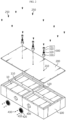
- FIG. 1 is a schematic perspective view of a battery pack according to an embodiment of the present disclosure
- FIG. 2 is an exploded perspective view of the primary elements of the battery pack in FIG. 1 .
- the battery pack 1 may include a battery module 10, a pack tray 100 that accommodates the battery module 10 therein and has a top opening, a pack cover 200 disposed on the top of the pack tray 100 so as to seal an accommodation space 220 in which the battery module 10 is accommodated, and a variable coupling part 300 that couples the pack tray 100 and the pack cover 200 to each other and elastically couples the pack cover 200 to the pack tray 100 such that the accommodation space 220 is variably expanded in response to an increase in the pressure of venting gas generated from the battery module 10 when an event occurs.
- the battery module 10 includes a cell assembly produced by stacking battery cells, and a module case 12 for accommodating the cell assembly.
- the pack tray 100 is a component to protect the battery modules 10 from external impacts or the like and may be made of a material with excellent mechanical rigidity. As shown in FIGS. 1 and 2 , an accommodation space 220 is provided to accommodate at least one battery module 10 therein.
- the pack tray 100 has a horizontal partition wall 110 (in the Y-axis direction) and a vertical partition wall 120 (in the X-axis direction) that partition the interior of the pack tray 100.
- the heights of the horizontal partition wall 110 and vertical partition wall 120 are configured to be greater than the height of the battery module 10.
- the horizontal partition wall 110 and the vertical partition wall 120 protrude in the Z-axis direction more than the top surface of the battery module 10 accommodated in the pack tray 100, and the pack cover 200 covers the same to provide an accommodation space 220 equal to the separation gap between the battery module 10 and the pack cover 200.
- one horizontal partition wall 110 along the Y axis and one vertical partition wall 120 along the X axis are provided inside the pack tray 100 to accommodate four battery modules 10 in this embodiment, the scope of the present disclosure is not limited to the number of horizontal partition walls 110 and vertical partition walls 120 or the number of battery modules 10 accommodated in this embodiment.
- the pack cover 200 is disposed on the top of the pack tray 100 to seal the accommodation space 220 where the battery module 10 is accommodated.
- the pack cover 200 may be provided to completely cover the four battery modules 10, and the pack cover 200 may be made of aluminum or SUS and may have a slight curvature formed on the plate surface because bending or sagging thereof may occur depending on a change in internal pressure.
- the pack cover 200 has a plurality of bolt coupling holes 210 formed thereon.
- the bolt coupling holes 210 are provided in the central area of the pack cover 200 corresponding to the horizontal partition wall 110 and the vertical partition wall 120, as well as in the edge area of the pack cover 200.
- the bolt coupling hole 210 may have a size corresponding to the size of a bolt to be used, and in the case where the size or length of the expansion bolt 310 is greater than that of a fixing bolt 250 in this embodiment, the bolt coupling hole 210 in the central area may be configured larger and deeper than the bolt coupling hole 210 at the edge.
- the pack cover 200 is bolted to the top of the pack tray 100.
- the pack cover 200 is bolted to the pack tray 100 at the edge of the battery pack 1 using fixing bolts 250, thereby firmly fixing the same.
- the central area of the pack cover 200 is not bolted through the fixing bolts 250.
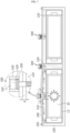
- FIG. 3 is a schematic top view of a battery pack according to an embodiment of the present disclosure
- FIG. 4 is a longitudinal cross-sectional view of the battery pack taken along line A-A' in FIG. 3
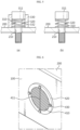
- FIG. 5 is a longitudinal cross-sectional view of a variable coupling part of a battery pack according to an embodiment of the present disclosure
- FIG. 6 is a partially perspective view of a gas outlet 400 region according to an embodiment of the present disclosure.
- variable coupling part 300 is disclosed.
- variable coupling part 300 elastically couples the pack cover 200 to the pack tray 100 so as to allow expansion (or micro-expansion) of the pack cover 200 through a variable coupling structure of the pack cover 200 to the pack tray 100 in response to an increase in internal pressure or thermal energy due to venting gas inside the battery pack 1.
- variable coupling part 300 may include: an expansion bolt 310 having one end that protrudes outwards from the pack cover 200 and the other end that passes through the pack cover 200 and is coupled to at least one of the horizontal partition wall 110 and the vertical partition wall 120; an elastic member 320 provided between the pack cover 200 and one end of the expansion bolt 310 to elastically bias the pack cover 200 in one direction; and a coupling housing 330 provided on the pack cover 200 and surrounding at least a portion of the elastic member 320 and the expansion bolt 310.
- the expansion bolt 310 is configured to be longer and thicker than the fixing bolt 250. Accordingly, one end of the expansion bolt 310, that is, a head 311, may protrude outwards from the pack cover 200, and the other end may pass through the pack cover 200 to be coupled to at least one of the horizontal partition wall 110 and the vertical partition wall 120. Referring to FIGS. 2 and 3 , the expansion bolts 310 are located in three places along the horizontal partition wall 110, and one of them is provided in the center of the pack tray 100 where the horizontal partition wall 110 and the vertical partition wall 120 intersect each other.
- the elastic member 320 is provided between the pack cover 200 and the head 311 of the expansion bolt 310.
- the elastic member 320 has one end supported by the head 311 of the expansion bolt 310 and the other end supported on the outer peripheral surface of the bolt coupling hole 210 on the pack cover 200.
- the elastic member 320 elastically biases the pack cover 200 in one direction (the Z direction in FIG. 1 ).
- the elastic member 320 may be a compression spring that provides resistance when the pack cover 200 is compressed toward the head 311 provided at one end of the expansion bolt 310.
- the elastic member 320 may act as a resistance force to reach an equilibrium state in which the pack cover 200 is bent to have a slight curvature, increasing the accommodation space 220 inside the battery pack 1, so the structural collapse of the battery pack 1 may be delayed.
- the elastic member 320 may perform a kind of buffering function to cushion the impact.
- stress concentration on the coupling portion (head 311) of the expansion bolt 310 or on the horizontal partition wall 110, the vertical partition wall 120, and the like of the pack tray 100 may also be reduced because the elastic member 320 is provided in the expansion bolt 310.
- the elastic modulus of the elastic member 320 may increase toward the central area of the pack cover 200.
- the elastic modulus of the elastic member 320 of the variable coupling part 300 disposed at the center of the pack cover 200 may be configured to be higher than the elastic modulus of the elastic member 320 of the left variable coupling part 300 (located between area 1 and area 2).
- the expansion gap d between the pack tray 100 and the pack cover 200 may widen (expand) more in the left variable coupling part 300 than in the variable coupling part at the center.
- the expansion gap d may not be produced in the variable coupling part 300 at the center.
- the accommodation spaces 220 may be connected to each other in areas 1 and 2, resulting in the expansion of the accommodation space 220, and the expansion of the local accommodation space 220 may be performed while areas 1 and 3 are still separated and partitioned from each other.
- variable coupling part 300 at the center of the pack cover 200 is also operated so that an expansion gap d is produced depending on the level of pressure and thermal energy inside the battery pack 1, the accommodation space 220 may fully expand to areas 3 and 4, in addition to areas 1 and 2.
- the coupling housing 330 is provided on the pack cover 200, and the coupling housing 330 may be a tubular body having a guiding hole formed in the longitudinal direction thereof.
- the thickness of the wall constituting the tubular body may be substantially the same as the thickness of the pack cover 200.
- the coupling housing 330 may be manufactured integrally with the pack cover 200, and alternatively, the coupling housing 330 may be manufactured separately and then coupled to the top surface of the pack cover 200 by welding, bolting, or the like.
- the coupling housing 330 is a part surrounding at least a portion of the elastic member 320 and the expansion bolt 310. That is, at least a portion of the expansion bolt 310 may be accommodated in the guiding hole 332 of the coupling housing 330 with the elastic member 320 inserted therein.
- the elastic member 320 may be effectively compressed or expanded inside the guiding hole 332, and the elastic member 320 may be accommodated inside the coupling housing 330 to prevent contact with external foreign substances or dust, thereby providing a function of protecting the elastic member 320 and blocking foreign substances from entering the battery pack 1.
- a gas outlet 400 through which the venting gas is discharged may be provided on a wall of the pack tray 100.
- a ring member 420 is provided on the outer peripheral surface of the gas outlet 400, and a rupture membrane 410 is provided to be connected to the ring member 420.
- the ring member 420 is coupled to the outer surface of the pack tray 100 through a bolt 430 and is configured to withstand the internal pressure of the battery pack 1.
- the rupture membrane 410 may have a discharge slit 411 configured to rupture when a pressure equal to or greater than the allowable pressure is applied thereto.
- the discharge slit 411 may be provided in the form of a 1-shaped or I-shaped incision in a dotted line. For example, if pressure equal to or greater than the designed allowable pressure is applied in the ignited battery module 10, the discharge slit 411 may rupture so that venting gas and thermal energy may be discharged.
- the left variable coupling part 300 when an event occurs in the battery module 10 in area 1, the left variable coupling part 300 is operated due to an increase in internal pressure and allows communication with the accommodation space 220 in area 2, and thereafter, the discharge slit 411 ruptures so that venting gas and thermal energy are discharged through the left gas outlet 400 of the battery pack 1.
- variable coupling part 300 may perform a buffering function to cushion the impact, thereby preventing the structural collapse of the battery pack 1.
- FIGS. 7 and 8 are diagrams schematically illustrating the operation state of a variable coupling part when venting gas and thermal energy spread in a battery pack according to an embodiment of the present disclosure
- FIG. 9 is a traverse cross-sectional view of a gas outlet and a rupture membrane in a battery pack according to an embodiment of the present disclosure.
- venting gas, flame, and thermal energy such as high-temperature particles including electrode active materials and aluminum particles are emitted.
- the variable coupling part 300 operates due to the internal pressure equal to or greater than the allowable pressure. That is, the internal pressure becomes greater than the resistance of the elastic member 320, so the elastic member 320 contracts and the pack cover 200 expands. At this time, as the pack cover 200 rises and the coupling housing 330 rises, the head 311 of the expansion bolt 310 relatively moves downwards inside the coupling housing 330.
- venting gas and the like are initially emitted only from the accommodation space 220 in area 1 in FIG. 3 to increase the internal pressure, and then the accommodation space 220 for venting gas and the like locally expands to area 2 due to the expansion gap d between the pack cover 200 and the horizontal partition wall 110.
- the pressure and thermal energy in the battery pack 1 may be effectively dispersed, thereby delaying the structural collapse of the battery pack 1 as long as possible.
- venting gas and the like are discharged through the gas outlet 400 shown in FIG. 9 . If the venting gas and thermal energy generated from area 1 in FIG. 3 spread to area 2 and if the internal pressure continues to increase to the allowable pressure or more, the discharge slit 411 may rupture to discharge the venting gas and the like, so that the internal pressure and thermal energy may be effectively dispersed and efficiently discharged from the battery pack 1, thereby delaying the structural collapse of the battery pack 1.
- variable coupling part 300 at the center point of the battery pack 1 may be operated with priority over the discharge process.
- the elastic modulus of the center point may be adjusted in consideration of the design pressure of the discharge slit 411, so that, as shown in FIG. 8 , the variable coupling part 300 at the center point may be operated prior to the discharge slit 411 if the internal pressure reaches a predetermined pressure or more after the variable coupling parts 300 are operated in areas 1 and 2.
- the accommodation space 220 may expand to area 2, area 3, and then area 4, and if the internal pressure continues to increase thereafter, venting gas and the like may be discharged through the discharge slit 411.
- FIG. 10 is a diagram illustrating a double pack cover and a variable coupling part according to another embodiment of the present disclosure
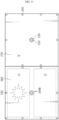
- FIG. 11 is a top view of a battery pack provided with left and right pack covers, respectively, according to another embodiment of the present disclosure
- FIG. 12 is a diagram schematically illustrating the operation state of a variable coupling part when venting gas and thermal energy spread in the battery pack in FIG. 11 .
- the battery pack according to another embodiment of the present disclosure includes a pack cover 200 in a double membrane structure in which the membranes are spaced a predetermined distance apart from each other. That is, as shown in FIG. 10 , the pack cover 200 may include a first pack cover 230 adjacent to the battery module 10 and a second pack cover 240 disposed above the first pack cover 230 so as to be spaced a predetermined distance apart from the first pack cover 230.
- variable coupling part 300A may include: an expansion bolt 310 having one end coupled to the horizontal partition wall 110 and the vertical partition wall 120; a first elastic member 321 provided between the first pack cover 230 and the second pack cover 240 to space the first pack cover 230 and the second pack cover 240 apart from each other; a second elastic member 322 provided between the second pack cover 240 and the expansion bolt 310 to elastically bias the second pack cover 240 in one direction; and a coupling housing 331 provided on the second pack cover 240 and accommodating the second elastic member 322 and the expansion bolt 310 therein.
- the first pack cover 230 and the second pack cover 240 are provided at a predetermined interval S, and the elastic member 321 is provided between the first pack cover 230 and the second pack cover 240 to space the first pack cover 230 and the second pack cover 240 apart from each other.
- the second elastic member 322 is provided between the second pack cover 240 and the expansion bolt 310 and serves to elastically bias the second pack cover 240 in one direction.
- variable coupling part 300 may buffer the impact through a buffering function in the improved double buffering structure, thereby preventing structural collapse of the battery pack.
- a battery pack according to another embodiment of the present disclosure may include a pack cover 200 that is divided into a left pack cover 260 and a right pack cover 270, and exclude the variable coupling part 300 from the center point of the battery pack.
- the left variable coupling part 300B may be operated so that the left pack cover 200 may expand, and if the allowable pressure is exceeded, gas may be discharged through the left gas outlet 400.
- this embodiment differs from the first embodiment in that the pack cover 200 in the first embodiment is completely divided into the left pack cover 260 and the right pack cover 270, so that no accommodation space 220 expand from area 1 or area 2 to area 3.
- the battery pack 1 may further include various devices for controlling the charging and discharging of the battery modules 10, such as a BMS (Battery Management System), a current sensor, a fuse, and the like.
- BMS Battery Management System
- the battery pack1 according to the present disclosure may be applied to vehicles such as electric vehicles or hybrid vehicles. That is, the vehicle according to the present disclosure may include the battery pack 1 according to the present disclosure.
- the battery pack 1 may be installed in the car body frame under the car seat or in the trunk space, and when installed in the vehicle, the arrangement order of the battery pack may be reversed if necessary.
Landscapes
- Chemical & Material Sciences (AREA)
- Chemical Kinetics & Catalysis (AREA)
- Electrochemistry (AREA)
- General Chemical & Material Sciences (AREA)
- Engineering & Computer Science (AREA)
- Aviation & Aerospace Engineering (AREA)
- Battery Mounting, Suspending (AREA)
- Gas Exhaust Devices For Batteries (AREA)
Abstract
Description
- The present application claims priority to
Korean Patent Application No. 10-2022-0117728 filed on September 19, 2022 - The present disclosure relates to a battery pack, and more specifically, it relates to a battery pack capable of delaying the structural collapse of the battery pack when thermal energy is accumulated and the internal pressure increases by venting gas or flame generated from the internal ignition of the battery module.
- Semi-permanent batteries that convert electrical energy into chemical energy and can be repeatedly charged and discharged are called secondary batteries distinguished from primary batteries that cannot be reused after one use.
- Secondary batteries include lithium secondary batteries, nickel-cadmium (Ni-Cd) batteries, lead-acid batteries, nickel-hydride (Ni-MH) batteries, zinc-air batteries, and alkaline manganese batteries. Among these, lead-acid batteries and lithium secondary batteries are the most widely commercialized secondary batteries.
- In particular, lithium secondary batteries have advantages such as high energy storage density, lightweight and miniaturized structures, excellent safety, a low discharge rate, and a long lifespan, so they are widely used as electric vehicle batteries nowadays. For reference, lithium secondary batteries are generally classified into cylindrical, prismatic, and pouch types depending on their manufacturing types, and their uses range from electric vehicle batteries to ESS batteries and other electrical devices.
- Currently, the operating voltage of one lithium secondary battery cell is approximately 2.5V to 4.5V. Therefore, in order to apply secondary batteries to an energy source for electric vehicles, a plurality of lithium-ion battery cells are connected in series and/or parallel to produce a battery module, and then the battery modules are connected in series and/or parallel to produce a battery pack.
- Meanwhile, since secondary batteries involve chemical reactions during charging and discharging, their performance may deteriorate when used at a temperature higher than the appropriate temperature, and failure of heat control to an appropriate temperature is likely to lead to unexpected ignition or explosion. In addition, since the battery module has a structure in which the secondary batteries are intensively stored inside a module housing, if any one secondary battery becomes a trigger cell due to heat propagation, it may transfer to the lithium secondary batteries and a chain reaction may occur, thereby generating a large amount of venting gas, flame, and high-temperature particles including electrode active materials and aluminum particles. The venting gas, flame, and high-temperature sparks accumulate thermal energy inside the battery pack, as well as inside the battery module, and increase internal pressure thereof, ultimately causing the structural collapse or explosion of the battery pack.
- Accordingly, structural improvement is required to delay structural collapse of the battery pack as long as possible and block propagation of thermal energy by effectively dispersing and efficiently discharging the pressure and thermal energy inside the battery pack before venting gas and flame generated from the initially ignited battery module are emitted and transfer to neighboring battery modules and the entire battery pack.
- The present disclosure has been designed to solve the problems of the related art, and therefore the present disclosure is directed to providing a battery pack capable of delaying structural collapse of the battery pack as long as possible and blocking propagation of thermal energy by effectively dispersing and efficiently discharging the pressure and thermal energy inside the battery pack before venting gas and flames generated from the initially ignited battery module are emitted and transfer to neighboring battery modules and the battery pack.
- The technical problems that the present disclosure seeks to solve are not limited to the above-mentioned problems, and other problems not mentioned above will be clearly understood by those skilled in the art from the description of the invention described below.
- A battery pack according to the present disclosure may include: a battery module; a pack tray configured to accommodate the battery module therein and have a top opening; a pack cover disposed on the top of the pack tray to seal an accommodation space where the battery module is accommodated; and a variable coupling part configured to connect the pack tray and the pack cover to each other and elastically couple the pack cover to the pack tray such that the accommodation space is variably expanded in response to an increase in pressure when an event occurs.
- The pack tray may have a horizontal partition wall and a vertical partition wall configured to partition the interior of the pack tray, and the variable coupling part may include: an expansion bolt having one end that protrudes outwards from the pack cover and the other end that passes through the pack cover and is coupled to at least one of the horizontal partition wall and the vertical partition wall; and an elastic member provided between the pack cover and one end of the expansion bolt to elastically bias the pack cover in one direction.
- The variable coupling part may further include a coupling housing provided on the pack cover and surrounding at least a portion of the elastic member and the expansion bolt.
- The coupling housing may be a tubular body having a guiding hole formed in the longitudinal direction thereof.
- The elastic member may be a compression spring that provides resistance when the pack cover is compressed toward a head provided at one end of the expansion bolt.
- The coupling housing may be manufactured integrally with the pack cover.
- An elastic modulus of the elastic member may increase toward the central area of the pack cover.
- A gas outlet through which the venting gas is discharged may be provided on a wall of the pack tray.
- A rupture membrane may be provided in the gas outlet, and a discharge slit configured to rupture when an allowable pressure or more is applied thereto may be provided in the rupture membrane.
- The discharge slit may be configured in the form of a 1-shaped or I-shaped incision in a dotted line.
- The pack cover may include a first pack cover adjacent to the battery module and a second pack cover disposed above the first pack cover so as to be spaced a predetermined distance apart from the first pack cover.
- The variable coupling part may include: an expansion bolt having one end coupled to the horizontal partition wall and the vertical partition wall; a first elastic member provided between the first pack cover and the second pack cover to space the first pack cover and the second pack cover apart from each other; a second elastic member provided between the second pack cover and the expansion bolt to elastically bias the second pack cover in one direction; and a coupling housing provided on the second pack cover and accommodating the second elastic member and the expansion bolt therein.
- The pack cover may include: a left pack cover provided on the left side of the vertical partition wall; and a right pack cover provided on the right side of the vertical partition wall, and the variable coupling part may be provided in the central area of the left pack cover and in the central area of the right pack cover.
- According to another aspect of the present disclosure, there may be provided a vehicle including the battery pack.
- According to one aspect of the present disclosure, it is possible to delay structural collapse of the battery pack as long as possible and block propagation of thermal energy by effectively dispersing and efficiently discharging the pressure and thermal energy inside the battery pack before venting gas and flames generated from the initially ignited battery module are emitted and transfer to neighboring battery modules and the entire battery pack.
- In addition, even if a situation changes suddenly due to an event, a variable coupling part may perform a buffering function to cushion the impact, thereby preventing the structural collapse of the battery pack.
- In addition, it is possible to lower stress concentration at a bolt joint due to leakage pressure of gas generated when an event occurs, thereby reducing maintenance costs of the battery pack.
- The effects of the present disclosure are not limited to the effects described above, and the effects not mentioned above will be clearly understood by those skilled in the art to which the present disclosure pertains from this specification and the accompanying drawings.
- The accompanying drawings illustrate a preferred embodiment of the present disclosure and, together with the detailed description of the invention, serve to provide further understanding of the technical idea of the present disclosure, and thus, the present disclosure is not construed as being limited to the drawings.
-
FIG. 1 is a schematic perspective view of a battery pack according to an embodiment of the present disclosure. -
FIG. 2 is an exploded perspective view of the primary elements of the battery pack inFIG. 1 . -
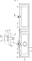
FIG. 3 is a schematic top view of a battery pack according to an embodiment of the present disclosure. -
FIG. 4 is a longitudinal cross-sectional view of the battery pack taken along line A-A' inFIG. 3 . -
FIG. 5 is a longitudinal cross-sectional view of a variable coupling part of a battery pack according to an embodiment of the present disclosure. -
FIG. 6 is a partially perspective view of a gas outlet region according to an embodiment of the present disclosure. -
FIGS. 7 and8 are diagrams schematically illustrating the operation state of a variable coupling part when venting gas and thermal energy spread in a battery pack according to an embodiment of the present disclosure. -
FIG. 9 is a traverse cross-sectional view of a gas outlet and a rupture membrane in a battery pack according to an embodiment of the present disclosure. -
FIG. 10 is a diagram illustrating a double pack cover and a variable coupling part according to another embodiment of the present disclosure. -
FIG. 11 is a top view of a battery pack provided with left and right pack covers, respectively, according to another embodiment of the present disclosure. -
FIG. 12 is a diagram schematically illustrating the operation state of a variable coupling part when venting gas and thermal energy spread in the battery pack inFIG. 11 . - Hereinafter, preferred embodiments of the present disclosure will be described in detail with reference to the accompanying drawings. Prior to the description, it should be understood that the terms used in the specification and the appended claims should not be construed as limited to general and dictionary meanings, but interpreted based on the meanings and concepts corresponding to technical aspects of the present disclosure on the basis of the principle that the inventor is allowed to define terms appropriately for the best explanation. Therefore, the configuration proposed in the embodiments and drawings of this specification indicates only the most preferable embodiment of the present disclosure and does not represent all technical ideas of the present disclosure, so it should be understood that various equivalents and modifications could be made thereto at the time of filing the application.
-
FIG. 1 is a schematic perspective view of a battery pack according to an embodiment of the present disclosure, andFIG. 2 is an exploded perspective view of the primary elements of the battery pack inFIG. 1 . - The
battery pack 1 according to this embodiment may include abattery module 10, apack tray 100 that accommodates thebattery module 10 therein and has a top opening, apack cover 200 disposed on the top of thepack tray 100 so as to seal anaccommodation space 220 in which thebattery module 10 is accommodated, and avariable coupling part 300 that couples thepack tray 100 and thepack cover 200 to each other and elastically couples thepack cover 200 to thepack tray 100 such that theaccommodation space 220 is variably expanded in response to an increase in the pressure of venting gas generated from thebattery module 10 when an event occurs. - The
battery module 10 includes a cell assembly produced by stacking battery cells, and amodule case 12 for accommodating the cell assembly. - The
pack tray 100 is a component to protect thebattery modules 10 from external impacts or the like and may be made of a material with excellent mechanical rigidity. As shown inFIGS. 1 and2 , anaccommodation space 220 is provided to accommodate at least onebattery module 10 therein. - The
pack tray 100 has a horizontal partition wall 110 (in the Y-axis direction) and a vertical partition wall 120 (in the X-axis direction) that partition the interior of thepack tray 100. In addition, the heights of thehorizontal partition wall 110 andvertical partition wall 120 are configured to be greater than the height of thebattery module 10. As shown inFIG. 2 , thehorizontal partition wall 110 and thevertical partition wall 120 protrude in the Z-axis direction more than the top surface of thebattery module 10 accommodated in thepack tray 100, and thepack cover 200 covers the same to provide anaccommodation space 220 equal to the separation gap between thebattery module 10 and thepack cover 200. Meanwhile, although onehorizontal partition wall 110 along the Y axis and onevertical partition wall 120 along the X axis are provided inside thepack tray 100 to accommodate fourbattery modules 10 in this embodiment, the scope of the present disclosure is not limited to the number ofhorizontal partition walls 110 andvertical partition walls 120 or the number ofbattery modules 10 accommodated in this embodiment. - The
pack cover 200 is disposed on the top of thepack tray 100 to seal theaccommodation space 220 where thebattery module 10 is accommodated. In this embodiment, thepack cover 200 may be provided to completely cover the fourbattery modules 10, and thepack cover 200 may be made of aluminum or SUS and may have a slight curvature formed on the plate surface because bending or sagging thereof may occur depending on a change in internal pressure. - The
pack cover 200 has a plurality of bolt coupling holes 210 formed thereon. The bolt coupling holes 210 are provided in the central area of thepack cover 200 corresponding to thehorizontal partition wall 110 and thevertical partition wall 120, as well as in the edge area of thepack cover 200. Thebolt coupling hole 210 may have a size corresponding to the size of a bolt to be used, and in the case where the size or length of theexpansion bolt 310 is greater than that of a fixingbolt 250 in this embodiment, thebolt coupling hole 210 in the central area may be configured larger and deeper than thebolt coupling hole 210 at the edge. - The
pack cover 200 is bolted to the top of thepack tray 100. Thepack cover 200 is bolted to thepack tray 100 at the edge of thebattery pack 1 using fixingbolts 250, thereby firmly fixing the same. Here, the central area of thepack cover 200 is not bolted through the fixingbolts 250. -
FIG. 3 is a schematic top view of a battery pack according to an embodiment of the present disclosure,FIG. 4 is a longitudinal cross-sectional view of the battery pack taken along line A-A' inFIG. 3 ,FIG. 5 is a longitudinal cross-sectional view of a variable coupling part of a battery pack according to an embodiment of the present disclosure, andFIG. 6 is a partially perspective view of agas outlet 400 region according to an embodiment of the present disclosure. - In the case where the
pack tray 100 and thepack cover 200 are bolted through the entire area thereof using the fixingbolts 250, if an event in which the venting gas and flame generated from the initially ignitedbattery module 10 spread inside thebattery pack 10 occurs, they may not be able to withstand the accumulated internal pressure, resulting in structural collapse or explosion of thebattery pack 1. Accordingly, in this embodiment, thevariable coupling part 300 is disclosed. - The
variable coupling part 300 elastically couples thepack cover 200 to thepack tray 100 so as to allow expansion (or micro-expansion) of thepack cover 200 through a variable coupling structure of thepack cover 200 to thepack tray 100 in response to an increase in internal pressure or thermal energy due to venting gas inside thebattery pack 1. - As shown in
FIGS. 3 to 5 , thevariable coupling part 300 may include: anexpansion bolt 310 having one end that protrudes outwards from thepack cover 200 and the other end that passes through thepack cover 200 and is coupled to at least one of thehorizontal partition wall 110 and thevertical partition wall 120; anelastic member 320 provided between thepack cover 200 and one end of theexpansion bolt 310 to elastically bias thepack cover 200 in one direction; and acoupling housing 330 provided on thepack cover 200 and surrounding at least a portion of theelastic member 320 and theexpansion bolt 310. - The
expansion bolt 310 is configured to be longer and thicker than the fixingbolt 250. Accordingly, one end of theexpansion bolt 310, that is, ahead 311, may protrude outwards from thepack cover 200, and the other end may pass through thepack cover 200 to be coupled to at least one of thehorizontal partition wall 110 and thevertical partition wall 120. Referring toFIGS. 2 and3 , theexpansion bolts 310 are located in three places along thehorizontal partition wall 110, and one of them is provided in the center of thepack tray 100 where thehorizontal partition wall 110 and thevertical partition wall 120 intersect each other. - The
elastic member 320 is provided between thepack cover 200 and thehead 311 of theexpansion bolt 310. Theelastic member 320 has one end supported by thehead 311 of theexpansion bolt 310 and the other end supported on the outer peripheral surface of thebolt coupling hole 210 on thepack cover 200. In addition, theelastic member 320 elastically biases thepack cover 200 in one direction (the Z direction inFIG. 1 ). Theelastic member 320 may be a compression spring that provides resistance when thepack cover 200 is compressed toward thehead 311 provided at one end of theexpansion bolt 310. - Accordingly, if the
pack cover 200 expands along theexpansion bolt 310 when the internal pressure of thepack cover 200 increases due to the occurrence of an event, theelastic member 320 may act as a resistance force to reach an equilibrium state in which thepack cover 200 is bent to have a slight curvature, increasing theaccommodation space 220 inside thebattery pack 1, so the structural collapse of thebattery pack 1 may be delayed. - In addition, when the event situation suddenly changes, for example, when the leakage pressure of venting gas increases rapidly or thermal energy is emitted explosively, the
elastic member 320 may perform a kind of buffering function to cushion the impact. - In addition, compared to the existing bolt coupling between the
pack tray 100 and thepack cover 200, stress concentration on the coupling portion (head 311) of theexpansion bolt 310 or on thehorizontal partition wall 110, thevertical partition wall 120, and the like of thepack tray 100 may also be reduced because theelastic member 320 is provided in theexpansion bolt 310. - In addition, the elastic modulus of the
elastic member 320 may increase toward the central area of thepack cover 200. Referring mainly toFIGS. 3 and4 , the elastic modulus of theelastic member 320 of thevariable coupling part 300 disposed at the center of thepack cover 200 may be configured to be higher than the elastic modulus of theelastic member 320 of the left variable coupling part 300 (located betweenarea 1 and area 2). - Therefore, when an event occurs in
area 1, the expansion gap d between thepack tray 100 and thepack cover 200 may widen (expand) more in the leftvariable coupling part 300 than in the variable coupling part at the center. Alternatively, the expansion gap d may not be produced in thevariable coupling part 300 at the center. In this case, theaccommodation spaces 220 may be connected to each other inareas accommodation space 220, and the expansion of thelocal accommodation space 220 may be performed whileareas - On the other hand, if the
variable coupling part 300 at the center of thepack cover 200 is also operated so that an expansion gap d is produced depending on the level of pressure and thermal energy inside thebattery pack 1, theaccommodation space 220 may fully expand toareas areas - The
coupling housing 330 is provided on thepack cover 200, and thecoupling housing 330 may be a tubular body having a guiding hole formed in the longitudinal direction thereof. Here, the thickness of the wall constituting the tubular body may be substantially the same as the thickness of thepack cover 200. In this embodiment, thecoupling housing 330 may be manufactured integrally with thepack cover 200, and alternatively, thecoupling housing 330 may be manufactured separately and then coupled to the top surface of thepack cover 200 by welding, bolting, or the like. - The
coupling housing 330 is a part surrounding at least a portion of theelastic member 320 and theexpansion bolt 310. That is, at least a portion of theexpansion bolt 310 may be accommodated in the guidinghole 332 of thecoupling housing 330 with theelastic member 320 inserted therein. - As a result, the
elastic member 320 may be effectively compressed or expanded inside the guidinghole 332, and theelastic member 320 may be accommodated inside thecoupling housing 330 to prevent contact with external foreign substances or dust, thereby providing a function of protecting theelastic member 320 and blocking foreign substances from entering thebattery pack 1. - Referring to
FIG. 6 , agas outlet 400 through which the venting gas is discharged may be provided on a wall of thepack tray 100. Aring member 420 is provided on the outer peripheral surface of thegas outlet 400, and arupture membrane 410 is provided to be connected to thering member 420. Thering member 420 is coupled to the outer surface of thepack tray 100 through abolt 430 and is configured to withstand the internal pressure of thebattery pack 1. - The
rupture membrane 410 may have adischarge slit 411 configured to rupture when a pressure equal to or greater than the allowable pressure is applied thereto. The discharge slit 411 may be provided in the form of a 1-shaped or I-shaped incision in a dotted line. For example, if pressure equal to or greater than the designed allowable pressure is applied in the ignitedbattery module 10, the discharge slit 411 may rupture so that venting gas and thermal energy may be discharged. - For example, in
FIG. 3 , when an event occurs in thebattery module 10 inarea 1, the leftvariable coupling part 300 is operated due to an increase in internal pressure and allows communication with theaccommodation space 220 inarea 2, and thereafter, the discharge slit 411 ruptures so that venting gas and thermal energy are discharged through theleft gas outlet 400 of thebattery pack 1. - According to this embodiment, it is possible to delay structural collapse of the
battery pack 1 as long as possible and block propagation of thermal energy by effectively dispersing and efficiently discharging the pressure and thermal energy inside the battery pack before venting gas and flame generated from the initially ignited battery module are emitted and transfer to neighboringbattery modules 10 and thebattery pack 1. - In addition, according to this embodiment, when the event situation suddenly changes, for example, when the internal pressure of the
battery pack 1 increases rapidly or thermal energy is emitted explosively, thevariable coupling part 300 may perform a buffering function to cushion the impact, thereby preventing the structural collapse of thebattery pack 1. - In addition, compared to the existing bolt coupling between the
pack tray 100 and thepack cover 200, stress concentration on the coupling portion (bolt head 311) of theexpansion bolt 310 or on thehorizontal partition wall 110, thevertical partition wall 120, and the like of thepack tray 100 may also be reduced because theelastic member 320 is provided in theexpansion bolt 310, thereby reducing the structural maintenance cost of thebattery pack 1. -
FIGS. 7 and8 are diagrams schematically illustrating the operation state of a variable coupling part when venting gas and thermal energy spread in a battery pack according to an embodiment of the present disclosure, andFIG. 9 is a traverse cross-sectional view of a gas outlet and a rupture membrane in a battery pack according to an embodiment of the present disclosure. - Hereinafter, a process of easily discharging venting gas to the outside according to this embodiment will be described in detail with reference to
FIGS. 1 to 7 . - First, when an event occurs in the
left battery module 10 inFIG. 7 , venting gas, flame, and thermal energy such as high-temperature particles including electrode active materials and aluminum particles are emitted. - Then, the internal pressure of the
accommodation space 220 increases, and thevariable coupling part 300 operates due to the internal pressure equal to or greater than the allowable pressure. That is, the internal pressure becomes greater than the resistance of theelastic member 320, so theelastic member 320 contracts and thepack cover 200 expands. At this time, as thepack cover 200 rises and thecoupling housing 330 rises, thehead 311 of theexpansion bolt 310 relatively moves downwards inside thecoupling housing 330. - Accordingly, venting gas and the like are initially emitted only from the
accommodation space 220 inarea 1 inFIG. 3 to increase the internal pressure, and then theaccommodation space 220 for venting gas and the like locally expands toarea 2 due to the expansion gap d between thepack cover 200 and thehorizontal partition wall 110. As a result, the pressure and thermal energy in thebattery pack 1 may be effectively dispersed, thereby delaying the structural collapse of thebattery pack 1 as long as possible. - Next, the venting gas and the like are discharged through the
gas outlet 400 shown inFIG. 9 . If the venting gas and thermal energy generated fromarea 1 inFIG. 3 spread toarea 2 and if the internal pressure continues to increase to the allowable pressure or more, the discharge slit 411 may rupture to discharge the venting gas and the like, so that the internal pressure and thermal energy may be effectively dispersed and efficiently discharged from thebattery pack 1, thereby delaying the structural collapse of thebattery pack 1. - Here, the
variable coupling part 300 at the center point of thebattery pack 1 may be operated with priority over the discharge process. For example, the elastic modulus of the center point may be adjusted in consideration of the design pressure of the discharge slit 411, so that, as shown inFIG. 8 , thevariable coupling part 300 at the center point may be operated prior to the discharge slit 411 if the internal pressure reaches a predetermined pressure or more after thevariable coupling parts 300 are operated inareas area 1 inFIG. 3 , theaccommodation space 220 may expand toarea 2,area 3, and thenarea 4, and if the internal pressure continues to increase thereafter, venting gas and the like may be discharged through the discharge slit 411. - According to this operational configuration, it is possible to delay structural collapse of the
battery pack 1 as long as possible and block propagation of thermal energy by effectively dispersing and efficiently discharging the pressure and thermal energy inside thebattery pack 1 before venting gas and flame generated from the initially ignitedbattery module 10 are emitted and transfer to neighboringbattery modules 10 and the battery pack. - Subsequently, other embodiments of the
battery pack 1 of the present disclosure will be briefly described with reference toFIGS. 10 to 12 . -
FIG. 10 is a diagram illustrating a double pack cover and a variable coupling part according to another embodiment of the present disclosure,FIG. 11 is a top view of a battery pack provided with left and right pack covers, respectively, according to another embodiment of the present disclosure, andFIG. 12 is a diagram schematically illustrating the operation state of a variable coupling part when venting gas and thermal energy spread in the battery pack inFIG. 11 . - The same reference numbers as those in the previous drawings indicate the same members, and redundant descriptions of the same members will be omitted, and a description will be made based on the differences from the above-described embodiment.
- Compared to the above-described embodiment, the battery pack according to another embodiment of the present disclosure includes a
pack cover 200 in a double membrane structure in which the membranes are spaced a predetermined distance apart from each other. That is, as shown inFIG. 10 , thepack cover 200 may include afirst pack cover 230 adjacent to thebattery module 10 and asecond pack cover 240 disposed above thefirst pack cover 230 so as to be spaced a predetermined distance apart from thefirst pack cover 230. - In addition, the
variable coupling part 300A may include: anexpansion bolt 310 having one end coupled to thehorizontal partition wall 110 and thevertical partition wall 120; a firstelastic member 321 provided between thefirst pack cover 230 and thesecond pack cover 240 to space thefirst pack cover 230 and thesecond pack cover 240 apart from each other; a secondelastic member 322 provided between thesecond pack cover 240 and theexpansion bolt 310 to elastically bias thesecond pack cover 240 in one direction; and acoupling housing 331 provided on thesecond pack cover 240 and accommodating the secondelastic member 322 and theexpansion bolt 310 therein. - The
first pack cover 230 and thesecond pack cover 240 are provided at a predetermined interval S, and theelastic member 321 is provided between thefirst pack cover 230 and thesecond pack cover 240 to space thefirst pack cover 230 and thesecond pack cover 240 apart from each other. In addition, the secondelastic member 322 is provided between thesecond pack cover 240 and theexpansion bolt 310 and serves to elastically bias thesecond pack cover 240 in one direction. - Since double pack covers 230 and 240 are provided, and since the first
elastic member 321 and the secondelastic member 322 in a double buffering structure are provided, when the event situation suddenly changes, for example, when the leakage pressure of venting gas increases rapidly or thermal energy is emitted explosively, thevariable coupling part 300 may buffer the impact through a buffering function in the improved double buffering structure, thereby preventing structural collapse of the battery pack. - In addition, it is possible to delay structural collapse of the battery pack as long as possible and block propagation of thermal energy by effectively dispersing and efficiently discharging the pressure and thermal energy inside the battery pack before venting gas and flame generated from the initially ignited
battery module 10 are emitted and transfer to neighboringbattery modules 10 and the battery pack. - A battery pack according to another embodiment of the present disclosure, compared to the first embodiment, may include a
pack cover 200 that is divided into aleft pack cover 260 and aright pack cover 270, and exclude thevariable coupling part 300 from the center point of the battery pack. - Accordingly, as shown in
FIG. 11 , when an event occurs inarea 1, the leftvariable coupling part 300B may be operated so that theleft pack cover 200 may expand, and if the allowable pressure is exceeded, gas may be discharged through theleft gas outlet 400. Here, this embodiment differs from the first embodiment in that thepack cover 200 in the first embodiment is completely divided into theleft pack cover 260 and theright pack cover 270, so that noaccommodation space 220 expand fromarea 1 orarea 2 toarea 3. - Meanwhile, although not shown, the
battery pack 1 according to the present disclosure may further include various devices for controlling the charging and discharging of thebattery modules 10, such as a BMS (Battery Management System), a current sensor, a fuse, and the like. - The battery pack1 according to the present disclosure may be applied to vehicles such as electric vehicles or hybrid vehicles. That is, the vehicle according to the present disclosure may include the
battery pack 1 according to the present disclosure. Thebattery pack 1 may be installed in the car body frame under the car seat or in the trunk space, and when installed in the vehicle, the arrangement order of the battery pack may be reversed if necessary. - Although terms indicating directions such as up, down, left, right, front, and back are used in this specification, it is obvious to those skilled in the art that these terms are only for convenience of explanation and may vary depending on the location of the target object or the location of the observer. As described above, although the present disclosure has been described with reference to limited embodiments and drawings, the present disclosure is not limited thereto, and various modifications and variations are possible within the technical idea of the present disclosure and the scope of equivalence of the claims to be described below by those skilled in the art to which the present disclosure pertains.
Claims (14)
- A battery pack comprising:a battery module;a pack tray configured to accommodate the battery module therein and have a top opening;a pack cover disposed on the top of the pack tray to seal an accommodation space where the battery module is accommodated; anda variable coupling part configured to connect the pack tray and the pack cover to each other and elastically couple the pack cover to the pack tray such that the accommodation space is variably expanded in response to an increase in pressure when an event occurs.
- The battery pack according to claim 1,wherein the pack tray has a horizontal partition wall and a vertical partition wall configured to partition the interior of the pack tray, andwherein the variable coupling part comprises:an expansion bolt having one end that protrudes outwards from the pack cover and the other end that passes through the pack cover and is coupled to at least one of the horizontal partition wall and the vertical partition wall; andan elastic member provided between the pack cover and one end of the expansion bolt to elastically bias the pack cover in one direction.
- The battery pack according to claim 2,
wherein the variable coupling part further comprises a coupling housing provided on the pack cover and surrounding at least a portion of the elastic member and the expansion bolt. - The battery pack according to claim 3,
wherein the coupling housing is configured as a tubular body having a guiding hole formed in the longitudinal direction thereof. - The battery pack according to claim 3,
wherein the coupling housing is manufactured integrally with the pack cover. - The battery pack according to claim 2,
wherein the elastic member is a compression spring that provides resistance when the pack cover is compressed toward a head provided at one end of the expansion bolt. - The battery pack according to claim 2,
wherein an elastic modulus of the elastic member increases toward the central area of the pack cover. - The battery pack according to claim 5,
wherein a gas outlet through which the venting gas is discharged is provided on a wall of the pack tray. - The battery pack according to claim 8,wherein a rupture membrane is provided in the gas outlet, andwherein a discharge slit configured to rupture when an allowable pressure or more is applied thereto is provided in the rupture membrane.
- The battery pack according to claim 9,
wherein the discharge slit is configured in the form of a 1-shaped or I-shaped incision in a dotted line. - The battery pack according to claim 1,
wherein the pack cover comprises a first pack cover adjacent to the battery module and a second pack cover disposed above the first pack cover so as to be spaced a predetermined distance apart from the first pack cover. - The battery pack according to claim 11,
wherein the variable coupling part comprises:an expansion bolt having one end coupled to the horizontal partition wall and the vertical partition wall;a first elastic member provided between the first pack cover and the second pack cover to space the first pack cover and the second pack cover apart from each other; a second elastic member provided between the second pack cover and the expansion bolt to elastically bias the second pack cover in one direction; anda coupling housing provided on the second pack cover and accommodating the second elastic member and the expansion bolt therein. - The battery pack according to claim 1,
wherein the pack cover comprises:a left pack cover provided on the left side of the vertical partition wall; anda right pack cover provided on the right side of the vertical partition wall, andwherein the variable coupling part is provided in the central area of the left pack cover and in the central area of the right pack cover. - A vehicle comprising the battery pack according to any one of claims 1 to 13.
Applications Claiming Priority (2)
| Application Number | Priority Date | Filing Date | Title |
|---|---|---|---|
| KR1020220117728A KR20240039326A (en) | 2022-09-19 | 2022-09-19 | Battery pack having variable coupling part for preventing structure collapse |
| PCT/KR2023/014098 WO2024063489A1 (en) | 2022-09-19 | 2023-09-18 | Battery pack having variable coupling portion for preventing structural collapse |
Publications (2)
| Publication Number | Publication Date |
|---|---|
| EP4550556A1 true EP4550556A1 (en) | 2025-05-07 |
| EP4550556A4 EP4550556A4 (en) | 2026-01-21 |
Family
ID=90454922
Family Applications (1)
| Application Number | Title | Priority Date | Filing Date |
|---|---|---|---|
| EP23868541.6A Pending EP4550556A4 (en) | 2022-09-19 | 2023-09-18 | BATTERY PACK WITH VARIABLE COUPLING PART TO PREVENT STRUCTURAL COLLAPSE |
Country Status (5)
| Country | Link |
|---|---|
| EP (1) | EP4550556A4 (en) |
| JP (1) | JP2025518575A (en) |
| KR (1) | KR20240039326A (en) |
| CN (1) | CN119013833A (en) |
| WO (1) | WO2024063489A1 (en) |
Families Citing this family (8)
| Publication number | Priority date | Publication date | Assignee | Title |
|---|---|---|---|---|
| KR20250144783A (en) * | 2024-03-27 | 2025-10-13 | 주식회사 엘지에너지솔루션 | Battery pack and Vehicle including the same |
| KR20250149064A (en) * | 2024-04-08 | 2025-10-15 | 주식회사 엘지에너지솔루션 | Battery pack and vehicle including the same |
| KR20250149065A (en) * | 2024-04-08 | 2025-10-15 | 주식회사 엘지에너지솔루션 | Battery pack and vehicle including the same |
| KR20250149063A (en) * | 2024-04-08 | 2025-10-15 | 주식회사 엘지에너지솔루션 | Battery pack and vehicle including the same |
| CN121312008A (en) * | 2024-04-16 | 2026-01-09 | 株式会社Lg新能源 | battery pack |
| KR20250159463A (en) * | 2024-05-02 | 2025-11-11 | 주식회사 엘지에너지솔루션 | Battery pack |
| KR20250171758A (en) * | 2024-05-30 | 2025-12-09 | 주식회사 엘지에너지솔루션 | Battery pack |
| KR20260022112A (en) * | 2024-08-07 | 2026-02-19 | 주식회사 엘지에너지솔루션 | Battery pack |
Family Cites Families (12)
| Publication number | Priority date | Publication date | Assignee | Title |
|---|---|---|---|---|
| JP4358245B2 (en) * | 2007-03-09 | 2009-11-04 | レノボ・シンガポール・プライベート・リミテッド | Battery pack and portable electronic device |
| KR101247390B1 (en) * | 2011-11-08 | 2013-03-25 | 세방전지(주) | Multi divided battery pack for hybrid vehicle |
| JP6702554B2 (en) * | 2016-10-04 | 2020-06-03 | 株式会社東芝 | Explosion-proof waterproof case |
| JP6988308B2 (en) * | 2017-09-22 | 2022-01-05 | 日産自動車株式会社 | Battery pack system |
| US11901538B2 (en) * | 2018-09-27 | 2024-02-13 | Research Institute Of Industrial Science & Technology | Sodium secondary battery module |
| CN115380429A (en) * | 2020-03-30 | 2022-11-22 | 株式会社村田制作所 | Battery pack and electric vehicle |
| KR20220065601A (en) * | 2020-11-13 | 2022-05-20 | 주식회사 엘지에너지솔루션 | Battery pack having a structure capable of swelling control and Vehicle including the same |
| KR20220117728A (en) | 2021-02-17 | 2022-08-24 | (주)씨에스이엔엘 | Water meter freeze protection apparatus |
| KR102785711B1 (en) * | 2021-02-18 | 2025-03-26 | 에스케이온 주식회사 | Battery pack |
| CN215008446U (en) * | 2021-03-29 | 2021-12-03 | 襄阳晟欣机电有限公司 | Special battery box for explosion-proof engine |
| CN215342842U (en) * | 2021-07-23 | 2021-12-28 | 北京中职北方教育科技有限公司 | New energy battery convenient to equipment |
| CN216720050U (en) * | 2021-10-11 | 2022-06-10 | 徐州途威新能源有限公司 | Explosion-proof flame retardant structure of automobile-used lithium cell |
-
2022
- 2022-09-19 KR KR1020220117728A patent/KR20240039326A/en active Pending
-
2023
- 2023-09-18 CN CN202380032841.8A patent/CN119013833A/en active Pending
- 2023-09-18 EP EP23868541.6A patent/EP4550556A4/en active Pending
- 2023-09-18 JP JP2024569017A patent/JP2025518575A/en active Pending
- 2023-09-18 WO PCT/KR2023/014098 patent/WO2024063489A1/en not_active Ceased
Also Published As
| Publication number | Publication date |
|---|---|
| KR20240039326A (en) | 2024-03-26 |
| WO2024063489A1 (en) | 2024-03-28 |
| CN119013833A (en) | 2024-11-22 |
| JP2025518575A (en) | 2025-06-17 |
| EP4550556A4 (en) | 2026-01-21 |
Similar Documents
| Publication | Publication Date | Title |
|---|---|---|
| CN119013833A (en) | Battery pack having variable coupling part for preventing structural collapse | |
| EP4391184B1 (en) | Battery pack having double top cover with venting gas passage | |
| EP4199226A1 (en) | Battery module, and battery pack and vehicle comprising same | |
| JP7785784B2 (en) | Battery Module | |
| EP4087047B1 (en) | Battery module, battery pack comprising the same, and vehicle. | |
| KR20240116261A (en) | Battery pack and vehicle including the same | |
| EP4567996A2 (en) | Battery module | |
| KR20230047957A (en) | Battery cell, battery, electric device, battery cell manufacturing method and equipment | |
| EP4435955A1 (en) | Battery pack | |
| KR20220164048A (en) | Battery, electrical device, method for manufacturing battery and equipment therefor | |
| EP4651283A1 (en) | Battery pack and vehicle including same | |
| EP4730535A1 (en) | Battery module | |
| EP4632918A1 (en) | Battery pack | |
| EP4668454A1 (en) | Battery pack and vehicle including same | |
| EP4738569A1 (en) | Battery pack and vehicle including same | |
| KR20240054010A (en) | Battery pack having blocking part for electrical connection | |
| EP4683086A1 (en) | Battery pack and vehicle including same | |
| EP4730501A1 (en) | Battery module, battery pack and vehicle including same | |
| EP4675817A1 (en) | Battery pack | |
| EP4708488A1 (en) | Battery module, and battery pack and vehicle including same | |
| US20260142271A1 (en) | Battery assembly | |
| KR20250167410A (en) | Battery pack and Vehicle including the same | |
| KR20240101317A (en) | Battery pack | |
| KR20260012566A (en) | Battery module, Battery pack and vehicle including the same | |
| KR20260018637A (en) | Battery pack and vehicle including the same |
Legal Events
| Date | Code | Title | Description |
|---|---|---|---|
| STAA | Information on the status of an ep patent application or granted ep patent |
Free format text: STATUS: THE INTERNATIONAL PUBLICATION HAS BEEN MADE |
|
| PUAI | Public reference made under article 153(3) epc to a published international application that has entered the european phase |
Free format text: ORIGINAL CODE: 0009012 |
|
| STAA | Information on the status of an ep patent application or granted ep patent |
Free format text: STATUS: REQUEST FOR EXAMINATION WAS MADE |
|
| 17P | Request for examination filed |
Effective date: 20250128 |
|
| AK | Designated contracting states |
Kind code of ref document: A1 Designated state(s): AL AT BE BG CH CY CZ DE DK EE ES FI FR GB GR HR HU IE IS IT LI LT LU LV MC ME MK MT NL NO PL PT RO RS SE SI SK SM TR |
|
| DAV | Request for validation of the european patent (deleted) | ||
| DAX | Request for extension of the european patent (deleted) | ||
| A4 | Supplementary search report drawn up and despatched |
Effective date: 20251219 |
|
| RIC1 | Information provided on ipc code assigned before grant |
Ipc: H01M 50/333 20210101AFI20251215BHEP Ipc: H01M 50/24 20210101ALI20251215BHEP Ipc: H01M 50/342 20210101ALI20251215BHEP Ipc: H01M 50/244 20210101ALI20251215BHEP Ipc: H01M 50/209 20210101ALI20251215BHEP Ipc: H01M 50/249 20210101ALI20251215BHEP Ipc: H01M 50/204 20210101ALI20251215BHEP Ipc: H01M 50/271 20210101ALI20251215BHEP |