EP4550552A1 - Electric power storage module - Google Patents
Electric power storage module Download PDFInfo
- Publication number
- EP4550552A1 EP4550552A1 EP23831474.4A EP23831474A EP4550552A1 EP 4550552 A1 EP4550552 A1 EP 4550552A1 EP 23831474 A EP23831474 A EP 23831474A EP 4550552 A1 EP4550552 A1 EP 4550552A1
- Authority
- EP
- European Patent Office
- Prior art keywords
- power storage
- electric power
- storage module
- module according
- spacer
- Prior art date
- Legal status (The legal status is an assumption and is not a legal conclusion. Google has not performed a legal analysis and makes no representation as to the accuracy of the status listed.)
- Pending
Links
Images







Classifications
-
- H—ELECTRICITY
- H01—ELECTRIC ELEMENTS
- H01M—PROCESSES OR MEANS, e.g. BATTERIES, FOR THE DIRECT CONVERSION OF CHEMICAL ENERGY INTO ELECTRICAL ENERGY
- H01M50/00—Constructional details or processes of manufacture of the non-active parts of electrochemical cells other than fuel cells, e.g. hybrid cells
- H01M50/20—Mountings; Secondary casings or frames; Racks, modules or packs; Suspension devices; Shock absorbers; Transport or carrying devices; Holders
- H01M50/204—Racks, modules or packs for multiple batteries or multiple cells
- H01M50/207—Racks, modules or packs for multiple batteries or multiple cells characterised by their shape
- H01M50/213—Racks, modules or packs for multiple batteries or multiple cells characterised by their shape adapted for cells having curved cross-section, e.g. round or elliptic
-
- H—ELECTRICITY
- H01—ELECTRIC ELEMENTS
- H01M—PROCESSES OR MEANS, e.g. BATTERIES, FOR THE DIRECT CONVERSION OF CHEMICAL ENERGY INTO ELECTRICAL ENERGY
- H01M50/00—Constructional details or processes of manufacture of the non-active parts of electrochemical cells other than fuel cells, e.g. hybrid cells
- H01M50/30—Arrangements for facilitating escape of gases
-
- H—ELECTRICITY
- H01—ELECTRIC ELEMENTS
- H01M—PROCESSES OR MEANS, e.g. BATTERIES, FOR THE DIRECT CONVERSION OF CHEMICAL ENERGY INTO ELECTRICAL ENERGY
- H01M50/00—Constructional details or processes of manufacture of the non-active parts of electrochemical cells other than fuel cells, e.g. hybrid cells
- H01M50/30—Arrangements for facilitating escape of gases
- H01M50/35—Gas exhaust passages comprising elongated, tortuous or labyrinth-shaped exhaust passages
-
- H—ELECTRICITY
- H01—ELECTRIC ELEMENTS
- H01M—PROCESSES OR MEANS, e.g. BATTERIES, FOR THE DIRECT CONVERSION OF CHEMICAL ENERGY INTO ELECTRICAL ENERGY
- H01M50/00—Constructional details or processes of manufacture of the non-active parts of electrochemical cells other than fuel cells, e.g. hybrid cells
- H01M50/30—Arrangements for facilitating escape of gases
- H01M50/394—Gas-pervious parts or elements
-
- Y—GENERAL TAGGING OF NEW TECHNOLOGICAL DEVELOPMENTS; GENERAL TAGGING OF CROSS-SECTIONAL TECHNOLOGIES SPANNING OVER SEVERAL SECTIONS OF THE IPC; TECHNICAL SUBJECTS COVERED BY FORMER USPC CROSS-REFERENCE ART COLLECTIONS [XRACs] AND DIGESTS
- Y02—TECHNOLOGIES OR APPLICATIONS FOR MITIGATION OR ADAPTATION AGAINST CLIMATE CHANGE
- Y02E—REDUCTION OF GREENHOUSE GAS [GHG] EMISSIONS, RELATED TO ENERGY GENERATION, TRANSMISSION OR DISTRIBUTION
- Y02E60/00—Enabling technologies; Technologies with a potential or indirect contribution to GHG emissions mitigation
- Y02E60/10—Energy storage using batteries
Definitions
- the present disclosure relates to an electric power storage module having an opening at a case for discharging gas.
- An electric power storage module including a chargeable/dischargeable secondary battery is used as a power source for portable devices, electric vehicles, and the like.
- a large electric power storage module used as a power source of an electric vehicle includes a plurality of cell holders holding a plurality of cells (cell batteries). Each battery is charged and discharged in accordance with chemical reaction. Therefore, gas may be generated inside the battery depending on the situation, and the electric power storage module has a structure for discharging the generated gas.
- Patent Literature 1 discloses a gas discharge mechanism of an electric power storage module.
- Patent Literature 1 JP 6574987 B
- the gas discharge mechanism improves reliability of the electric power storage module. However, with the recent increase in capacity of a power storage device, further improvement in reliability as an electric power storage module is desired.
- the electric power storage module includes a plurality of power storage devices; a case that contains the plurality of power storage devices; an opening that is provided to a portion of the case for discharging gas in the case; a porous inner filter that is located in the opening; a porous outer filter that is located outside the inner filter with a gap therebetween; and a spacer that is provided between the inner filter and the outer filter, holds the gap therebetween, and in which an opening through which the gas passes is formed.
- the use of the spacer increases the reliability of the filter.
- FIG. 1 is a perspective view illustrating an external configuration of an electric power storage module according to an embodiment.
- an electric power storage module 10 contains a plurality of batteries as an example of the power storage device in a case 12 having a quadrangular prism shape.
- a gas discharge portion 14 is provided on one end side of the case 12. Therefore, the gas generated from the battery inside the case 12 is discharged from the gas discharge portion 14 to the outside.
- the gas discharge portion 14 is provided with a holding plate 34 at one end (front side) in the axial direction thereof.
- Four nuts 62 for fixing four fixing shafts 60 penetrating the interior of the case 12 are provided in the periphery of the holding plate 34, and the case 12 is tightened from both ends in the axial direction by screwing the nuts 62 into the end of the fixing shaft 60.
- a positive electrode may be provided at a central portion, and a negative electrode may be provided in the periphery, and the other end of the fixing shaft 60 may be appropriately fixed to the end surface on the other end side of the case 12.
- a plurality of batteries are contained in the case 12, and for example, four electric power storage blocks in which 10 batteries are assembled can be located in the axial direction.
- a circuit board 50 on which a circuit for controlling charging and discharging of the battery is mounted may also be contained in the case 12.
- the electric power storage module 10 of the present disclosure is used as a power source of, for example, an electric motorcycle, an assist bicycle, an electric wheelchair, an electric tricycle, or an electric cart.
- the present disclosure does not specify the application of the electric power storage module 10, and the electric power storage module can also be used as a power source for various electric devices used outdoors such as electric tools.
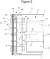
- FIG. 2 is a cross sectional view illustrating a configuration of the gas discharge portion 14 provided on one end side of the case 12, and
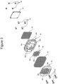
- FIG. 3 is an exploded perspective view illustrating a configuration of the gas discharge portion 14.
- the case 12 is open at both ends in the longitudinal direction and is provided with the gas discharge portion 14 so as to cover an opening on one end side.
- the gas discharge portion 14 has a cap 26 attached to an end of the case 12 in the longitudinal direction.
- the cap 26 includes a donut-shaped outer edge 26a and a cylindrical portion 26b extending from an outer peripheral end of the outer edge 26a toward a portion of the case 12 containing the battery 30 (referred to as a back side), and a back side end of the cylindrical portion 26b is fitted into a back-side distal end of the case 12 in the axial direction.
- An opening 26c is formed in a central portion of the cap 26, and a spacer 28 is fitted into the opening.
- the cap 26 has two (eight in total) holes at each of four corners, four holes on the inner side in the width direction are bolt holes 26d for inserting bolts 40 for fixing respective members of the gas discharge portion 14, and four holes on the outer side are shaft holes 26e for inserting fixing shafts 60 for fixing both ends of the case 12.
- the opening 26c of the cap 26 has an octagonal shape
- the outer shape of the spacer 28 fitted into the opening is also an octagonal shape.
- the spacer 28 is formed by combining a beam 28a radially extending from the center and an annular beam 28b having different radii, and an opening 28c is formed between the beam 28a and the beam 28b.
- An inner filter 36 is located on the case 12 side (back side) of the spacer 28.
- the inner filter 36 covers the opening 26c of the cap 26.
- an outer filter 38 is located on the side (referred to as the front side) of the spacer 28 opposite to the case 12 so as to cover the opening 26c and also cover the outside surface of the cap 26 in the axial direction.
- the inner filter 36 is larger than the opening 26c.
- the inner filter 36 is smaller than the cap 26, and has bolt holes at the four corners thereof, but does not have shaft holes.
- the outer filter 38 has substantially the same shape as the end surface of the cap 26 in the axial direction and has bolt holes and shaft holes at the four corners. Note that a porous material is adopted for the inner filter 36 and the outer filter, but any material may be used as long as gas can pass therethrough to remove a predetermined solid material.
- the inner filter 36 and the outer filter 38 may be, for example, punching metal in which an infinite number of through holes are formed in an aluminum plate.
- two filters of the inner filter 36 and the outer filter 38 are provided. The release of a solid material can be suppressed, and a cooling effect by heat transfer can also be expected for the gas passing through these filters.
- the filtering effect can be increased by shifting the positions of the openings of the inner filter 36 and the outer filter 38 with respect to the gas flowing direction.
- the holding plate 34 is located outside the outer filter 38 in the axial direction.
- the holding plate 34 includes a peripheral portion corresponding to the end surface of the cap 26 in the axial direction and a central portion corresponding to the spacer 28 inside the peripheral portion.
- Four bolt holes and four shaft holes are provided at four corners of the peripheral portion.
- the central portion of the holding plate 34 has substantially the same shape as the spacer 28. That is, beams 34a and 34b of the holding plate 34 correspond to the beams 28a and 28b of the spacer 28, and an opening 34c of the holding plate 34 corresponds to the opening 28c of the spacer 28. Therefore, the resistance of the spacer 28 and the holding plate 34 to the flow of the gas can be suppressed to be small.
- a protection partition wall 44 is located via four pipe-shaped partition wall spacers 42.
- the protection partition wall 44 has a shape corresponding to the inner filter 36 and is provided with bolt holes at four corners.
- Bolt holes are provided at the four corners of the holding plate 34, the outer filter 38, the cap 26, the inner filter 36, and the protection partition wall 44 at the same position in the longitudinal direction, and the four partition wall spacers 42 are also provided at positions corresponding to the bolt holes.
- the four bolts 40 are inserted into the bolt holes of the respective members from the front side of the holding plate 34 and pass through the partition wall spacer 42, so that the distal ends thereof protrude to the back side of the protection partition wall 44. Then, by screwing nuts 46 to the distal ends of the four bolts 40, the holding plate 34 and the protection partition wall 44 are tightened toward the internal members, and the respective members are fixed.
- FIG. 4 is an enlarged view of the spacer 28 in FIG. 2 .
- the beams 28a in the radial direction and the annular beams 28b are combined.
- Two beams 28a-1 in the radial direction cross the entire spacer 28 to form an X shape.
- two annular beams 28b-1 and 28b-2 having different diameters are concentrically located.
- two (four in total) radial beams 28a-2 on one side radially extending from the inner annular beam 28b-2 are provided in the width direction
- two radial beams 28a-3 extending upward and downward from the outer annular beam 28b-1 are provided in the longitudinal direction.
- Each of the beams 28a and 28b has a quadrangular prism shape, four openings 28c are formed inside, eight openings 28c are formed in an intermediate portion, and 10 openings 28c are formed between the beams and the outer cap 26.
- the spacer 28 abuts on the inner filter 36 on one surface in the axial direction and abuts on the outer filter 38 on the other surface in the axial direction, thereby promoting heat dissipation from the inner filter 36 to the outer filter 38 via the spacer 28. Therefore, when the spacer 28 has a heat capacity higher than those of the inner filter 36 and the outer filter 38, heat dissipation from the inner filter 36 to the outer filter 38 is further promoted.
- all of the spacer 28, the inner filter 36, and the outer filter 38 are preferably made of metal from the viewpoint of thermal conductivity.
- the spacer 28 may be integrated with at least one of the inner filter 36 and the outer filter 38.
- FIG. 5 is an enlarged view of the holding plate 34 in FIG. 2 .
- the beams 34a in the radial direction and annular beams 34b are combined. That is, the beams 34a-1, 34a-2, and 34a-3 are provided corresponding to the radial beams 28a-1, 28a-2, and 28a-3 of the spacer 28, and the beams 34b-1 and 34b-2 overlapping the annular beams 28b-1 and 28b-2 are provided, thereby forming the openings 34c of the holding plate 34 overlapping the openings 28c of the spacer 28.
- the openings and the beams of the spacer 28 overlap the openings and the beams of the holding plate 34, the gas passing through the spacer 28 and the holding plate 34 easily flows.
- the rigidity of the gas discharge portion 14 is increased by the spacer 28 and the holding plate 34 abutting on each other via the outer filter, heat is easily drawn mainly from the spacer 28 to the holding plate 34.
- FIG. 6 is a cross-sectional view at a position shifted from the center in the axial direction where the bolt 40 is located.
- the bolts 40 are located so as to pass through the holding plate 34, the outer filter 38, the outer edge 26a of the cap 26, the inner filter 36, and the bolts 40 further pass through the partition wall spacer 42 located on the inner side of the inner filter 36 in the axial direction, and the nuts 46 are fixed with the protection partition wall 44 interposed therebetween.
- the protection partition wall 44 is pressed against the partition wall spacer 42, and the holding plate 34, the outer filter 38, the outer edge 26a of the cap 26, and the inner filter 36 are tightened by the partition wall spacer 42 and the heads of the bolts 40.
- the holding plate 34, the outer filter 38, and the cap 26 are provided with shaft holes at four corners.
- the fixing shafts 60 indicated by broken lines in FIGS. 3 and 6 pass through these shaft holes and are tightened to the holding plate 34 by the nuts 62.
- shaft holes are also provided to the end surface of the case 12 on the other end side, and the fixing shaft 60 passes through the shaft hole at the other end, and the nuts can be screwed into the distal ends thereof. Accordingly, the nut 62 is fastened to the end of the fixing shaft 60, whereby the cap 26 and the case 12 can be fixed.
- the fixing shafts 60 may pass through also a holder that contains the battery 30 therein.
- the case 12 has a hollow quadrangular cylindrical shape and contains the plurality of batteries 30 therein.
- the plurality of batteries 30 are contained in the holder 24, and the holder 24 includes the main body 24a that individually supports the batteries 30 and ends 24b that cover the end of the main body 24a in the axial direction, and both are fastened by bolts 24c. That is, after the batteries 30 are contained in the main body 24a, the ends 24b are fixed to the main body 24a with the bolts 24c.
- the battery 30 which is an example of the power storage device of the present disclosure is, for example, a cylindrical lithium ion secondary battery and has both end electrodes as described above.
- the battery 30 is not limited to the present embodiment and may be another power storage device such as a nickel-metal hydride battery, a nickel-cadmium battery, or a lithium polymer battery, a capacitor, or the like.
- the battery 30 is a cylindrical secondary battery, but is not limited to this embodiment, and may be a rectangular secondary battery.
- the case 12 is formed of metal such as aluminum, has strength, and is excellent in heat dissipation.
- grooves or projections may be formed in the case 12 along the longitudinal direction in order to improve strength.
- the surface thereof may be covered with a laminate film, vinyl, or the like.
- the cap 26 may be configured with hard plastic or metal.
- the inner filter 36 and the outer filter 38 may be, for example, punching metal in which an infinite number of through holes are formed in an aluminum plate.
- the protection partition wall 44 may be made of a material having a melting point higher than those of the inner filter 36 and the outer filter 38.
- iron, stainless steel, or ceramics may be used.
- aluminum, iron, stainless steel, ceramics, or the like can be used.
- the bolt 40 has a screw head at one end and is fastened with the nut 46 at the other end, but these may be hard plastic or metal.
- the gas generated from battery 30 is first detoured outward by the protection partition wall 44.
- the gas is filtered by two filters of the inner filter 36 and the outer filter 38 and then discharged to the outside of the case 12. Therefore, the flow rate of the generated gas is weakened, and the gas is discharged with the solid material removed by the filter.
- the longer the path to discharge the lower the temperature. Therefore, it is possible to suppress an adverse effect on peripheral devices due to the discharged gas.
- the spacer 28 is positioned between the inner filter 36 and the outer filter 38 to maintain a gap therebetween.
- deformation of swelling of the outer filter 38 by the holding plate 34 can be suppressed, and deformation of the inner filter 36 can be suppressed via the spacer 28.
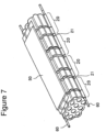
- FIGS. 7 to 19 illustrate an example of a structure of a battery and a holder that contains the battery.
- the electric power storage module 10 includes a plurality of electric power storage blocks 20.
- the electric power storage module 10 includes the four electric power storage blocks 20 connected in series in the longitudinal direction but is not limited to the present embodiment.
- An inter-block member 21 is provided between the electric power storage blocks 20.
- the inter-block member 21 includes a wall surface that separates the electric power storage blocks 20 from each other, a cushioning material, and the like.
- the electric power storage block 20 is a unit in which a plurality of batteries 30 are arranged in multiple stages. Also, in the electric power storage block 20, the plurality of batteries 30 are located such that the longitudinal direction (height direction, axial direction) of batteries 30 is parallel to the first direction. Note that in the electric power storage block 20, the plurality of batteries 30 may be provided not in multiple stages but in only one stage. Further, the electric power storage blocks 20 may not be located side by side in the first direction via the inter-block member 21 and may be electric power storage modules in which the plurality of electric power storage blocks 20 are arranged side by side in a direction orthogonal to the first direction. At this time, each electric power storage block 20 may have a wall erected on an edge of an upper surface of a holder 31 and a lid which abuts on the upper end of the wall to form a duct between the lid and the upper surface.
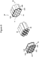
- the electric power storage block 20 includes the plurality of batteries 30 and the holders 31 and 32 that hold respective batteries 30. As illustrated in FIG. 8 , the holders 31 and 32 have partition walls 35 that form containing recesses for containing the plurality of batteries 30.
- 10 batteries 30 are arranged in three rows (three parallel units described below) of three, four, and three batteries in a hexagonal lattice pattern shape (or in a stacked shape).
- the electric power storage blocks 20 may be configured with a plurality of parallel units each including the plurality of batteries 30.
- the parallel unit may be configured by connecting electrodes on both end surfaces of the battery 30 in the first direction in parallel by lead plates.
- the batteries 30 may be arranged in a line.
- the parallel units adjacent to each other may be arranged such that the polarities of the electrodes on the end surfaces of the batteries 30 are in directions opposite to each other.
- the parallel units located adjacently to each other may have a configuration of being connected in series.
- the power storage device including the battery 30 is, for example, a cylindrical lithium ion secondary battery and has electrodes on both end surfaces in the axial direction as described above.
- the battery 30 is not limited to the present embodiment and may be another secondary battery such as a nickel-metal hydride battery, a nickel-cadmium battery, or a lithium polymer battery, a capacitor, or the like.
- the battery 30 is a cylindrical secondary battery, but is not limited to this embodiment, and may be a rectangular secondary battery.
- the battery 30 may include an electrode group in which a positive electrode and a negative electrode each having a band shape are wound while facing each other with a separator interposed therebetween, a can (outer casing) that contains the electrode group together with an electrolyte and has a cylindrical portion and a bottom portion that closes one end of the cylindrical portion, and a sealing member that closes an opening at the other end of the can.
- the sealing member may be electrically connected to one electrode of the positive electrode and the negative electrode via a lead or the like.
- the can may be electrically connected to the other electrode of the positive electrode and the negative electrode via a lead or the like.
- an insulating member such as a gasket may be interposed between the sealing member and the opening of the can.
- a groove 30A may be formed in a region between an electrode assembly and the sealing member. Furthermore, on the inner peripheral surface of the can, a portion where the groove 30A is formed may protrude toward the inside of the can. Note that the groove 30Ais referred to as a recess.
- a sealing member may be located on the projection by the groove, and an end at the opening of the can may be bent inward of the can in the radial direction. The sealing member can be fixed in the first direction (axial direction, height direction of battery) by the end and the projection.
- the outer peripheral edge of the sealing member and the opening of the can may be welded and sealed.
- a recess for engaging with a rib 70 may be formed on the outer surface of the can.
- the outer casing including the can may be configured with a conductive agent such as metal when electrically connected to the electrode assembly and may be configured with an insulating material such as a resin when not electrically connected to the electrode assembly.
- the battery 30 may have an exhaust portion at least at one end in the first direction. With this configuration, gas accumulated in the battery 30 can be discharged to the outside of the battery 30 and the outside of the electric power storage block 20 via the exhaust portion.
- the exhaust portion may be an irreversible valve that opens by breaking the imprint, or may be a reversible valve that further compresses the compressed elastic body with gas pressure to form an exhaust path.
- Exhaust portions may be formed at both ends of the battery 30 in the first direction.
- the holders 31 and 32 are divided into two parts in a substantially central portion of the battery 30 in a longitudinal direction (first direction, axial direction, height direction).
- the holder 31 holds one sides of the plurality of batteries 30 arranged in a hexagonal lattice pattern.
- the holder 31 includes a holding portion 31A integrally formed with cylindrical housing parts into which one ends of the plurality of arranged batteries 30 in the longitudinal direction are respectively fitted, and a side wall 31B formed along the outer periphery of the plurality of arranged batteries 30.
- a plurality of openings penetrating in the first direction (the longitudinal direction of the battery) are formed in each of the holding portion 31A of the holder 31 and the holding portion 32A of the holder 32.
- the holder 31 may cover both ends of the outer peripheral surface of the battery 30 in the axial direction to cover the insertion port of the housing part of the holder 31 with a plate material such as a lid. At this time, the plate material may be fastened to the corner of the holder 31 with a screw or the like.
- a hole 32H penetrating in the longitudinal direction is provided in the side wall 31B of the holder 31.
- the fixing shaft 60 is inserted into the hole 32H and is fitted to the inter-block member 21.
- the holes 32H are provided at two locations, but are not limited to the present embodiment, and may be provided according to the number of the fixing shafts 60.
- the holder 31 may have an electrolyte injection hole 31T into which a potting material is poured after the battery 30 is contained and assembled in the holders 31 and 32.
- the holder 32 Since the holder 32 has the same configuration as the holder 31, the description thereof is omitted. An engagement portion that is formed at the other end of the side wall 31B of the holder 31 in the longitudinal direction is engaged with an engagement portion formed at one end of a side wall 32B of the holder 32 in the longitudinal direction, whereby the holder 31 and the holder 32 are connected.
- the partition walls 35 are formed so as to fill the gaps between the batteries 30 arranged in the hexagonal lattice pattern as described above.
- the partition wall 35 is formed of a material having some elasticity such as hard plastic or a potting material but is not limited to the present embodiment.
- the partition wall 35 may include a heat absorbing material such as aluminum hydroxide.
- the partition wall 35 is integrated with the holder 31 but may be separated.
- the rib 70 may be formed on the partition wall 35, and the rib 70 needs to have relatively large elasticity. Therefore, the partition wall 35 may be formed of a plastic material having relatively large elasticity. Examples of the upper plastic material include polycarbonate (PC).
- the rib 70 is provided on the inner surface of the housing part of battery 30.
- the rib 70 may be provided on the inner wall surface of the holder 32, or the ribs 70 may be provided on both of the holders 31 and 32.
- FIGS. 9A and 9B are diagrams illustrating a configuration of the rib 70 in the holder 31, FIG. 9A is a perspective view, and FIG. 9B is an enlarged view of main parts.
- the holder 31 is integrally formed including the partition wall 35, and the holder 31 has a housing part 72 that is a cylindrical hole containing one end of battery 30 in the first direction.
- the rib 70 is formed on an inner wall 72A of the housing part 72.
- the rib 70 is a ridge projection extending in the axial direction of the housing part 72 and extends partway in the axial direction (toward the center in the axial direction of the battery 30) from the bottom portion of the housing part 72.
- the plurality of ribs 70 may be provided so that the battery 30 is held in the housing part 72 with the plurality of ribs 70.
- the battery 30 can be more stably held.
- FIG. 10 is a diagram for describing holding of the battery 30 in the holder 31 using the rib 70, where the left diagram illustrates a status before insertion of the battery 30, and the right diagram illustrates a status after insertion of the battery 30.
- the rib 70 is a ridge projection illustrated in FIG. 5 , and one rib is provided on the inner wall 72A of the housing part 72.
- the battery 30 has the annular groove 30A near one end. That is, the groove 30A extending in the circumferential direction on the side surface of the battery 30 is formed between a body part 30B serving as the main body of the battery 30 and a head part 30C in which the electrode and the like are formed.
- the groove 30A is formed in the battery 30 by, for example, using an outer cylinder (case) of the battery 30 as a cylindrical container having one end opening, containing an electrode assembly and an electrolyte solution therein, and then caulking an open end of a cylindrical portion to fix a sealing member onto the groove 30A.
- a diameter based on an inner side end of the rib 70 of the housing part 72 is smaller than diameters of the body part 30B and the head part 30C of the battery 30.
- the difference in diameter is within an elastically deformable range of the rib 70 (including a deformation range of the inner wall 72A), and the battery 30 can be inserted into the housing part 72 by displacement of the rib 70.
- the rib 70 By pressing the battery 30 in the axial direction, the rib 70 is pressed against the head part 30C and the body part 30B to be elastically recessed, and the head part 30C and the body part 30B are inserted (or press-fitted) into the housing part 72.
- the battery 30 is inserted into the housing part 72 to a predetermined value, a portion of the rib 70 facing the groove 30A swells toward the inside of the groove 30A. That is, the rib 70 is pressed outward in the portion facing the head part 30C and the body part 30B of the rib 70, but there is no reaction force from the battery 30 side in the portion facing the groove 30A. Therefore, in the rib 70, a swelling part 70A that swells toward the original position is formed. Note that, at the end of the head part 30C and the body part 30B on the groove 30A side, the rib 70 slightly moves to the groove 30A side, and thus the swelling part 70A may become larger accordingly.
- the rib 70 that is a ridge projection is formed on the inner wall 72A of the housing part 72 of the holder 31 containing the battery 30. Then, the battery 30 is inserted while deforming the rib 70. Therefore, no special work is required when the battery 30 is inserted. When the insertion is completed, the rib 70 swells toward the groove 30A, and the swelling part 70A is formed. Therefore, the movement of the battery 30 in the axial direction can be reliably prevented. Since the rib 70 is integrally formed with the holder 31, attachment work is not required in the formation, and the rib can be formed by a normal molding process.
- the shape of the swelling part 70A since the shape of the swelling part 70A is used, a reaction force using the shape can be generated against an impact, and the battery 30 can be reliably held.
- the dimension of the rib 70 in the first direction is larger than the maximum dimension of the groove 30A in the first direction, a portion other than the groove 30A can be held, so the battery 30 can be more firmly held by the rib 70.
- FIG. 10 is a case where the three ribs 70 are provided, and thus the rib 70 is shown on only one of the two illustrated inner walls 72A of the housing part 72.
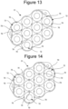
- FIGS. 11 to 14 are plan views of the holder 31 as viewed from the axial direction
- FIG. 11 illustrates an example in which the one rib 70 is provided
- FIG. 12 illustrates an example in which the two ribs 70 are provided
- FIG. 13 illustrates an example in which three ribs 70 are provided
- FIG. 14 illustrates an example in which four ribs 70 are provided.
- the rib may be provided at any position in the circumferential direction of the housing part 72.
- the ribs 70 having the same shape may be provided at the same position in all the housing part 72.
- the plurality of ribs 70 provided in one housing part 72 may be arranged at equal intervals in the circumferential direction.
- FIG. 15 is a diagram illustrating an example in which the shape of the rib 70 is changed.
- the rib 70 is enlarged in the circumferential direction.
- the dimension of the rib 70 in the circumferential direction is longer than that in the first direction.
- FIG. 16 is a diagram illustrating a state in which battery 30 is held by the holders 31 and 32.
- the rib 70 is provided on the inner wall 72A of the housing part 72 of the holder 31.
- the ribs 70 are provided on the inner walls 72A on both sides of the housing part 72.
- FIG. 17 is a plan view of an example in which a notch is formed in the bottom surface of the holder 31.
- six notches 80 are provided in the periphery of a bottom portion 72B of the one housing part 72 that is in contact with the inner wall 72A.
- the notches 80 are larger than the ribs 70 and are positioned at equal intervals in the circumferential direction.
- the ribs 70 are provided at positions corresponding to every other three of the six notches 80. Therefore, the end of the rib 70 on the bottom surface side is positioned in the notch 80.
- the inner wall 72A of the housing part 72 on which the rib 70 is provided is elastically deformed easily, the battery 30 is easily inserted, and the rib 70 can be more reliably pressed against the outer peripheral surface of the battery 30.
- the notch 80 may be an opening penetrating in the first direction or a thinner portion than the other portion in the bottom portion of the housing part 72.
- FIG. 18 is a diagram illustrating an example in which a support column 90 is provided instead of the partition wall 35. That is, the holder 31 has the 10 housing parts 72 for containing the batteries 30. Among the 10 housing parts 72, the two inner housing parts 72 are each partitioned by the six support columns 90 and the upper surface of the holder 31. Each of the eight housing parts 72 positioned around the two housing parts 72 is partitioned by the side wall 31B of the holder 31, the upper surface of the holder 31, and the two support columns 90. Also, the three ribs 70 are positioned around one housing part 72. Therefore, some of the ribs 70 are provided on the inner side surface of the side wall 31B, and the remaining ribs 70 are provided on the side surface of the support column 90.
- the battery 30 can be reliably held by the swelling part 70A of the rib 70. Since the use of the partition wall 35 can be suppressed by using the support column 90, the distance between the pair of batteries 30 adjacent to each other can be easily narrowed.
- FIGS. 19A and 19B are diagrams illustrating an example in which a side surface of the battery 30 is covered with a sleeve 100, and a hole is formed in the sleeve 100, (A) illustrates an example in which a slit 102 is formed as a recess, and (B) illustrates an example in which a round hole 104 is formed as a recess.
- the sleeve 100 that covers the outer peripheral surface of the battery 30 (particularly, the can) is provided.
- the sleeve 100 is formed of metal such as plastic or aluminum and can protect the battery 30.
- a plastic or aluminum thin plate having a size corresponding to the size of the battery 30 is wound around and bonded to the side surface of the battery 30.
- the plurality of slits 102 extending in the axial direction are formed side by side in the circumferential direction at positions corresponding to the ribs 70 of the housing part 72 of the sleeve 100.
- the width of the slit 102 can be set smaller than that of the rib 70. Accordingly, in the rib 70, a part thereof swells toward the inside of the slit 102. Also, the width of the slit 102 may be larger than the width of the rib 70. Accordingly, a part of the rib 70 swells toward the inside of the slit 102.
- the portion of the rib 70 facing the slit 102 swells toward the outer peripheral surface of the battery 30 by the thickness of the sleeve 100, and the swelling part 70A is formed therein to be engaged (or fitted) with the end of the slit 102. Accordingly, the battery 30 can be held in the holder 31 by engagement (or fitting) between the swelling part 70A and the slit 102.
- the beam between the slits 102 can move by setting the battery 30 in the portion where the slit 102 is formed to be a recessed part.
- the beam can be provided at a position corresponding to the groove 30A of the battery 30.
- the length of the slit 102 in the axial direction may be larger or smaller than the width of the groove 30A in the axial direction.
- the rib 70 is restricted in the axial direction of the swelling part 70A by both ends of the groove 30A.
- the axial direction of the swelling part 70A is restricted by both ends of the slit 102 in the axial direction.
- the groove 30A may not be present at the position of the battery 30 corresponding to the slit 102, and the diameter of the battery 30 at the end may be small. Also with this configuration, the swelling part 70A can be regulated by the slit 102, and thus the vertical movement of the battery 30 can be regulated by the rib 70.
- the round hole 104 is provided instead of the slit 102. Also with this configuration, a part of the rib 70 swells toward the round hole 104, the swelling part 70A is formed therein, and the same function and effect as the slit 102 can be obtained.
- the hole provided in the sleeve 100 is not limited to the slit 102 or the round hole 104 and may have any shape as long as the swelling part 70A can be received.
- a hollow may be formed instead of a penetrating hole as a recess.
- FIGS. 7 to 19B The features of the battery module illustrated in FIGS. 7 to 19B are illustrated below.
- An electric power storage module includes:
- the electric power storage module according to the present disclosure can be used as a power source of an electric vehicle or the like.
Landscapes
- Chemical & Material Sciences (AREA)
- Chemical Kinetics & Catalysis (AREA)
- Electrochemistry (AREA)
- General Chemical & Material Sciences (AREA)
- Battery Mounting, Suspending (AREA)
- Gas Exhaust Devices For Batteries (AREA)
Abstract
Description
- The present disclosure relates to an electric power storage module having an opening at a case for discharging gas.
- An electric power storage module including a chargeable/dischargeable secondary battery is used as a power source for portable devices, electric vehicles, and the like.
- A large electric power storage module used as a power source of an electric vehicle includes a plurality of cell holders holding a plurality of cells (cell batteries). Each battery is charged and discharged in accordance with chemical reaction. Therefore, gas may be generated inside the battery depending on the situation, and the electric power storage module has a structure for discharging the generated gas.
- For example,
Patent Literature 1 discloses a gas discharge mechanism of an electric power storage module. - Patent Literature 1:
JP 6574987 B - The gas discharge mechanism improves reliability of the electric power storage module. However, with the recent increase in capacity of a power storage device, further improvement in reliability as an electric power storage module is desired.
- The electric power storage module according to the present disclosure includes a plurality of power storage devices; a case that contains the plurality of power storage devices; an opening that is provided to a portion of the case for discharging gas in the case; a porous inner filter that is located in the opening; a porous outer filter that is located outside the inner filter with a gap therebetween; and a spacer that is provided between the inner filter and the outer filter, holds the gap therebetween, and in which an opening through which the gas passes is formed.
- According to the present disclosure, the use of the spacer increases the reliability of the filter.
-
-
FIG. 1 is a perspective view illustrating an electric power storage module in an embodiment of the present disclosure. -
FIG. 2 is a cross sectional view illustrating a configuration of a gas discharge portion provided on one end side of a case in the embodiment. -
FIG. 3 is an exploded perspective view illustrating a configuration of the gas discharge portion in the embodiment. -
FIG. 4 is an enlarged view of aspacer 28 inFIG. 2 . -
FIG. 5 is an enlarged view of aholding plate 34 inFIG. 2 . -
FIG. 6 is a diagram illustrating a configuration of a gas discharge portion provided on one end side of a case in the embodiment and is a cross-sectional view at a position shifted from a center in an axial direction in which a bolt is located. -
FIG. 7 is a perspective view illustrating the electric power storage module in an exploded manner. -
FIG. 8 is a perspective view of an electric power storage block in an exploded manner. -
FIG. 9A is a perspective view illustrating a configuration of a rib in the electric power storage module. -
FIG. 9B is an enlarged view of main parts illustrating the configuration of the rib in the electric power storage module. -
FIG. 10 is a diagram for describing holding of the power storage device by a holder using the rib in the electric power storage module, where the left diagram illustrates a status before insertion of the power storage device, and the right diagram illustrates a status after insertion of the power storage device. -
FIG. 11 is a plan view of a holder in the electric power storage module as viewed in the axial direction and illustrates an example in which there is one rib. -
FIG. 12 is a plan view of a holder in the electric power storage module as viewed in the axial direction and illustrates an example in which there are two ribs. -
FIG. 13 is a plan view of a holder in the electric power storage module as viewed in the axial direction and illustrates an example in which there are three ribs. -
FIG. 14 is a plan view of a holder in the electric power storage module as viewed in the axial direction and illustrates an example in which there are four ribs. -
FIG. 15 is a diagram illustrating an example in which the shape of the rib in the electric power storage module is changed. -
FIG. 16 is a diagram illustrating a state in which the power storage device is held by the holder in the electric power storage module. -
FIG. 17 is a plan view illustrating an example in which a notch is formed in a bottom surface of the holder in the electric power storage module. -
FIG. 18 is a diagram illustrating an example in which a support column is provided instead of a partition wall in the electric power storage module. -
FIG. 19A is a diagram illustrating an example in which a side surface of the power storage device in the electric power storage module is covered with a sleeve, and a slit is formed in the sleeve. -
FIG. 19B is a diagram illustrating an example in which a side surface of the power storage device in the electric power storage module is covered with a sleeve, and a round hole is formed as a recess in the sleeve. - Hereinafter, embodiments of the present disclosure will be described with reference to the drawings. Note that the following embodiments do not limit the present disclosure, and a configuration obtained by selectively combining a plurality of examples is also included in the present disclosure.
-
FIG. 1 is a perspective view illustrating an external configuration of an electric power storage module according to an embodiment. In this example, an electricpower storage module 10 contains a plurality of batteries as an example of the power storage device in acase 12 having a quadrangular prism shape. Agas discharge portion 14 is provided on one end side of thecase 12. Therefore, the gas generated from the battery inside thecase 12 is discharged from thegas discharge portion 14 to the outside. - The
gas discharge portion 14 is provided with aholding plate 34 at one end (front side) in the axial direction thereof. Fournuts 62 for fixing fourfixing shafts 60 penetrating the interior of thecase 12 are provided in the periphery of theholding plate 34, and thecase 12 is tightened from both ends in the axial direction by screwing thenuts 62 into the end of thefixing shaft 60. Note that, on the surface on the other end side of thecase 12, for example, a positive electrode may be provided at a central portion, and a negative electrode may be provided in the periphery, and the other end of thefixing shaft 60 may be appropriately fixed to the end surface on the other end side of thecase 12. - Here, a plurality of batteries are contained in the
case 12, and for example, four electric power storage blocks in which 10 batteries are assembled can be located in the axial direction. In addition, acircuit board 50 on which a circuit for controlling charging and discharging of the battery is mounted may also be contained in thecase 12. - In addition, four
bolts 40 are provided around the holding plate 34 (on the inner side of the fixing shaft 60) to fix the respective members of thegas discharge portion 14 as described below. - The electric
power storage module 10 of the present disclosure is used as a power source of, for example, an electric motorcycle, an assist bicycle, an electric wheelchair, an electric tricycle, or an electric cart. However, the present disclosure does not specify the application of the electricpower storage module 10, and the electric power storage module can also be used as a power source for various electric devices used outdoors such as electric tools. -
FIG. 2 is a cross sectional view illustrating a configuration of thegas discharge portion 14 provided on one end side of thecase 12, andFIG. 3 is an exploded perspective view illustrating a configuration of thegas discharge portion 14. - The
case 12 is open at both ends in the longitudinal direction and is provided with thegas discharge portion 14 so as to cover an opening on one end side. - The
gas discharge portion 14 has acap 26 attached to an end of thecase 12 in the longitudinal direction. Thecap 26 includes a donut-shapedouter edge 26a and acylindrical portion 26b extending from an outer peripheral end of theouter edge 26a toward a portion of thecase 12 containing the battery 30 (referred to as a back side), and a back side end of thecylindrical portion 26b is fitted into a back-side distal end of thecase 12 in the axial direction. - An opening 26c is formed in a central portion of the
cap 26, and aspacer 28 is fitted into the opening. In addition, thecap 26 has two (eight in total) holes at each of four corners, four holes on the inner side in the width direction arebolt holes 26d for insertingbolts 40 for fixing respective members of thegas discharge portion 14, and four holes on the outer side areshaft holes 26e for inserting fixingshafts 60 for fixing both ends of thecase 12. - Here, the
opening 26c of thecap 26 has an octagonal shape, and the outer shape of thespacer 28 fitted into the opening is also an octagonal shape. Thespacer 28 is formed by combining abeam 28a radially extending from the center and anannular beam 28b having different radii, and anopening 28c is formed between thebeam 28a and thebeam 28b. - An
inner filter 36 is located on thecase 12 side (back side) of thespacer 28. Theinner filter 36 covers theopening 26c of thecap 26. Also, anouter filter 38 is located on the side (referred to as the front side) of thespacer 28 opposite to thecase 12 so as to cover theopening 26c and also cover the outside surface of thecap 26 in the axial direction. Theinner filter 36 is larger than theopening 26c. Also, theinner filter 36 is smaller than thecap 26, and has bolt holes at the four corners thereof, but does not have shaft holes. Meanwhile, theouter filter 38 has substantially the same shape as the end surface of thecap 26 in the axial direction and has bolt holes and shaft holes at the four corners. Note that a porous material is adopted for theinner filter 36 and the outer filter, but any material may be used as long as gas can pass therethrough to remove a predetermined solid material. - The
inner filter 36 and theouter filter 38 may be, for example, punching metal in which an infinite number of through holes are formed in an aluminum plate. In the present embodiment, two filters of theinner filter 36 and theouter filter 38 are provided. The release of a solid material can be suppressed, and a cooling effect by heat transfer can also be expected for the gas passing through these filters. - Furthermore, in order to increase the filtering effect, the filtering effect can be increased by shifting the positions of the openings of the
inner filter 36 and theouter filter 38 with respect to the gas flowing direction. - The holding
plate 34 is located outside theouter filter 38 in the axial direction. The holdingplate 34 includes a peripheral portion corresponding to the end surface of thecap 26 in the axial direction and a central portion corresponding to thespacer 28 inside the peripheral portion. Four bolt holes and four shaft holes are provided at four corners of the peripheral portion. - The central portion of the holding
plate 34 has substantially the same shape as thespacer 28. That is, beams 34a and 34b of the holdingplate 34 correspond to thebeams spacer 28, and anopening 34c of the holdingplate 34 corresponds to theopening 28c of thespacer 28. Therefore, the resistance of thespacer 28 and the holdingplate 34 to the flow of the gas can be suppressed to be small. - On the back side of the
inner filter 36, aprotection partition wall 44 is located via four pipe-shapedpartition wall spacers 42. Theprotection partition wall 44 has a shape corresponding to theinner filter 36 and is provided with bolt holes at four corners. - Bolt holes are provided at the four corners of the holding
plate 34, theouter filter 38, thecap 26, theinner filter 36, and theprotection partition wall 44 at the same position in the longitudinal direction, and the fourpartition wall spacers 42 are also provided at positions corresponding to the bolt holes. The fourbolts 40 are inserted into the bolt holes of the respective members from the front side of the holdingplate 34 and pass through thepartition wall spacer 42, so that the distal ends thereof protrude to the back side of theprotection partition wall 44. Then, by screwingnuts 46 to the distal ends of the fourbolts 40, the holdingplate 34 and theprotection partition wall 44 are tightened toward the internal members, and the respective members are fixed. -
FIG. 4 is an enlarged view of thespacer 28 inFIG. 2 . In this manner, thebeams 28a in the radial direction and theannular beams 28b are combined. Twobeams 28a-1 in the radial direction cross theentire spacer 28 to form an X shape. Meanwhile, twoannular beams 28b-1 and 28b-2 having different diameters are concentrically located. Further, two (four in total)radial beams 28a-2 on one side radially extending from the innerannular beam 28b-2 are provided in the width direction, and tworadial beams 28a-3 extending upward and downward from the outerannular beam 28b-1 are provided in the longitudinal direction. Each of thebeams openings 28c are formed inside, eightopenings 28c are formed in an intermediate portion, and 10openings 28c are formed between the beams and theouter cap 26. In addition, thespacer 28 abuts on theinner filter 36 on one surface in the axial direction and abuts on theouter filter 38 on the other surface in the axial direction, thereby promoting heat dissipation from theinner filter 36 to theouter filter 38 via thespacer 28. Therefore, when thespacer 28 has a heat capacity higher than those of theinner filter 36 and theouter filter 38, heat dissipation from theinner filter 36 to theouter filter 38 is further promoted. At this time, all of thespacer 28, theinner filter 36, and theouter filter 38 are preferably made of metal from the viewpoint of thermal conductivity. Also, thespacer 28 may be integrated with at least one of theinner filter 36 and theouter filter 38. -
FIG. 5 is an enlarged view of the holdingplate 34 inFIG. 2 . In this manner, thebeams 34a in the radial direction andannular beams 34b are combined. That is, thebeams 34a-1, 34a-2, and 34a-3 are provided corresponding to theradial beams 28a-1, 28a-2, and 28a-3 of thespacer 28, and thebeams 34b-1 and 34b-2 overlapping theannular beams 28b-1 and 28b-2 are provided, thereby forming theopenings 34c of the holdingplate 34 overlapping theopenings 28c of thespacer 28. As described above, since the openings and the beams of thespacer 28 overlap the openings and the beams of the holdingplate 34, the gas passing through thespacer 28 and the holdingplate 34 easily flows. When the rigidity of thegas discharge portion 14 is increased by thespacer 28 and the holdingplate 34 abutting on each other via the outer filter, heat is easily drawn mainly from thespacer 28 to the holdingplate 34. - In addition, in the holding
plate 34, fourbolt holes 34e through which thebolts 40 are inserted and fourshaft holes 34f through which the fixingshafts 60 are inserted are provided at four corners of aperipheral portion 34d corresponding to the end surface of thecap 26 in the axial direction. - Here,
FIG. 6 is a cross-sectional view at a position shifted from the center in the axial direction where thebolt 40 is located. In this manner, thebolts 40 are located so as to pass through the holdingplate 34, theouter filter 38, theouter edge 26a of thecap 26, theinner filter 36, and thebolts 40 further pass through thepartition wall spacer 42 located on the inner side of theinner filter 36 in the axial direction, and the nuts 46 are fixed with theprotection partition wall 44 interposed therebetween. That is, by tightening the nuts 46 to the end of thebolt 40, theprotection partition wall 44 is pressed against thepartition wall spacer 42, and the holdingplate 34, theouter filter 38, theouter edge 26a of thecap 26, and theinner filter 36 are tightened by thepartition wall spacer 42 and the heads of thebolts 40. - As illustrated in
FIG. 2 , the holdingplate 34, theouter filter 38, and thecap 26 are provided with shaft holes at four corners. The fixingshafts 60 indicated by broken lines inFIGS. 3 and6 pass through these shaft holes and are tightened to the holdingplate 34 by the nuts 62. Although not illustrated, shaft holes are also provided to the end surface of thecase 12 on the other end side, and the fixingshaft 60 passes through the shaft hole at the other end, and the nuts can be screwed into the distal ends thereof. Accordingly, thenut 62 is fastened to the end of the fixingshaft 60, whereby thecap 26 and thecase 12 can be fixed. Note that the fixingshafts 60 may pass through also a holder that contains thebattery 30 therein. - As illustrated in
FIGS. 3 and6 , thecase 12 has a hollow quadrangular cylindrical shape and contains the plurality ofbatteries 30 therein. In this example, the plurality ofbatteries 30 are contained in theholder 24, and theholder 24 includes themain body 24a that individually supports thebatteries 30 and ends 24b that cover the end of themain body 24a in the axial direction, and both are fastened bybolts 24c. That is, after thebatteries 30 are contained in themain body 24a, theends 24b are fixed to themain body 24a with thebolts 24c. - The
battery 30 which is an example of the power storage device of the present disclosure is, for example, a cylindrical lithium ion secondary battery and has both end electrodes as described above. Thebattery 30 is not limited to the present embodiment and may be another power storage device such as a nickel-metal hydride battery, a nickel-cadmium battery, or a lithium polymer battery, a capacitor, or the like. Thebattery 30 is a cylindrical secondary battery, but is not limited to this embodiment, and may be a rectangular secondary battery. - Here, the
case 12 is formed of metal such as aluminum, has strength, and is excellent in heat dissipation. In addition, grooves or projections may be formed in thecase 12 along the longitudinal direction in order to improve strength. Furthermore, in order to insulate themetal case 12, the surface thereof may be covered with a laminate film, vinyl, or the like. Thecap 26 may be configured with hard plastic or metal. Also, theinner filter 36 and theouter filter 38 may be, for example, punching metal in which an infinite number of through holes are formed in an aluminum plate. Theprotection partition wall 44 may be made of a material having a melting point higher than those of theinner filter 36 and theouter filter 38. For example, iron, stainless steel, or ceramics may be used. For thespacer 28 and the holdingplate 34, aluminum, iron, stainless steel, ceramics, or the like can be used. Thebolt 40 has a screw head at one end and is fastened with thenut 46 at the other end, but these may be hard plastic or metal. - With such a configuration, the gas generated from
battery 30 is first detoured outward by theprotection partition wall 44. As a result, it is possible to suppress the high-temperature gas from being directly blown to theinner filter 36. Then, the gas is filtered by two filters of theinner filter 36 and theouter filter 38 and then discharged to the outside of thecase 12. Therefore, the flow rate of the generated gas is weakened, and the gas is discharged with the solid material removed by the filter. In addition, the longer the path to discharge, the lower the temperature. Therefore, it is possible to suppress an adverse effect on peripheral devices due to the discharged gas. - In addition, the
spacer 28 is positioned between theinner filter 36 and theouter filter 38 to maintain a gap therebetween. In particular, it is possible to prevent theinner filter 36 from being pushed toward theouter filter 38 by the gas generated in the electric power storage module and theinner filter 36 from swelling. As theinner filter 36 swells and approaches theouter filter 38, it is possible to prevent one filter of theinner filter 36 and theouter filter 38 from blocking the opening of the other filter. This effect is particularly remarkable when the opening of theinner filter 36 and the opening of theouter filter 38 are located to be shifted from each other. Furthermore, deformation of swelling of theouter filter 38 by the holdingplate 34 can be suppressed, and deformation of theinner filter 36 can be suppressed via thespacer 28. -
FIGS. 7 to 19 illustrate an example of a structure of a battery and a holder that contains the battery. - As illustrated in
FIGS. 7 to 8 , the electricpower storage module 10 includes a plurality of electric power storage blocks 20. The electricpower storage module 10 includes the four electric power storage blocks 20 connected in series in the longitudinal direction but is not limited to the present embodiment. Aninter-block member 21 is provided between the electric power storage blocks 20. Theinter-block member 21 includes a wall surface that separates the electric power storage blocks 20 from each other, a cushioning material, and the like. - The electric
power storage block 20 is a unit in which a plurality ofbatteries 30 are arranged in multiple stages. Also, in the electricpower storage block 20, the plurality ofbatteries 30 are located such that the longitudinal direction (height direction, axial direction) ofbatteries 30 is parallel to the first direction. Note that in the electricpower storage block 20, the plurality ofbatteries 30 may be provided not in multiple stages but in only one stage. Further, the electric power storage blocks 20 may not be located side by side in the first direction via theinter-block member 21 and may be electric power storage modules in which the plurality of electric power storage blocks 20 are arranged side by side in a direction orthogonal to the first direction. At this time, each electricpower storage block 20 may have a wall erected on an edge of an upper surface of aholder 31 and a lid which abuts on the upper end of the wall to form a duct between the lid and the upper surface. - The electric
power storage block 20 includes the plurality ofbatteries 30 and theholders respective batteries 30. As illustrated inFIG. 8 , theholders partition walls 35 that form containing recesses for containing the plurality ofbatteries 30. - In the electric
power storage block 20 according to the present embodiment, 10batteries 30 are arranged in three rows (three parallel units described below) of three, four, and three batteries in a hexagonal lattice pattern shape (or in a stacked shape). - The electric power storage blocks 20 may be configured with a plurality of parallel units each including the plurality of
batteries 30. Here, the parallel unit may be configured by connecting electrodes on both end surfaces of thebattery 30 in the first direction in parallel by lead plates. In the parallel unit, thebatteries 30 may be arranged in a line. Further, the parallel units adjacent to each other may be arranged such that the polarities of the electrodes on the end surfaces of thebatteries 30 are in directions opposite to each other. Further, in the electricpower storage block 20, the parallel units located adjacently to each other may have a configuration of being connected in series. - The power storage device according to the present disclosure including the
battery 30 is, for example, a cylindrical lithium ion secondary battery and has electrodes on both end surfaces in the axial direction as described above. Thebattery 30 is not limited to the present embodiment and may be another secondary battery such as a nickel-metal hydride battery, a nickel-cadmium battery, or a lithium polymer battery, a capacitor, or the like. Thebattery 30 is a cylindrical secondary battery, but is not limited to this embodiment, and may be a rectangular secondary battery. - The
battery 30 may include an electrode group in which a positive electrode and a negative electrode each having a band shape are wound while facing each other with a separator interposed therebetween, a can (outer casing) that contains the electrode group together with an electrolyte and has a cylindrical portion and a bottom portion that closes one end of the cylindrical portion, and a sealing member that closes an opening at the other end of the can. The sealing member may be electrically connected to one electrode of the positive electrode and the negative electrode via a lead or the like. The can may be electrically connected to the other electrode of the positive electrode and the negative electrode via a lead or the like. When the sealing member and the can have different polarities, an insulating member such as a gasket may be interposed between the sealing member and the opening of the can. On the outer peripheral surface of the can, agroove 30A may be formed in a region between an electrode assembly and the sealing member. Furthermore, on the inner peripheral surface of the can, a portion where thegroove 30A is formed may protrude toward the inside of the can. Note that the groove 30Ais referred to as a recess. Inside the can, a sealing member may be located on the projection by the groove, and an end at the opening of the can may be bent inward of the can in the radial direction. The sealing member can be fixed in the first direction (axial direction, height direction of battery) by the end and the projection. When a through hole is provided in the sealing member, and a terminal connected to one electrode of the electrode assembly passes through the through hole, the outer peripheral edge of the sealing member and the opening of the can may be welded and sealed. In this case, a recess for engaging with arib 70 may be formed on the outer surface of the can. The outer casing including the can may be configured with a conductive agent such as metal when electrically connected to the electrode assembly and may be configured with an insulating material such as a resin when not electrically connected to the electrode assembly. Thebattery 30 may have an exhaust portion at least at one end in the first direction. With this configuration, gas accumulated in thebattery 30 can be discharged to the outside of thebattery 30 and the outside of the electricpower storage block 20 via the exhaust portion. The exhaust portion may be an irreversible valve that opens by breaking the imprint, or may be a reversible valve that further compresses the compressed elastic body with gas pressure to form an exhaust path. Exhaust portions may be formed at both ends of thebattery 30 in the first direction. - As illustrated in
FIG. 8 , theholders battery 30 in a longitudinal direction (first direction, axial direction, height direction). Theholder 31 holds one sides of the plurality ofbatteries 30 arranged in a hexagonal lattice pattern. Theholder 31 includes a holdingportion 31A integrally formed with cylindrical housing parts into which one ends of the plurality of arrangedbatteries 30 in the longitudinal direction are respectively fitted, and aside wall 31B formed along the outer periphery of the plurality of arrangedbatteries 30. A plurality of openings penetrating in the first direction (the longitudinal direction of the battery) are formed in each of the holdingportion 31A of theholder 31 and the holdingportion 32A of theholder 32. Through this opening, current collection and exhaust of the battery are performed. Note that, without using theholder 32, theholder 31 may cover both ends of the outer peripheral surface of thebattery 30 in the axial direction to cover the insertion port of the housing part of theholder 31 with a plate material such as a lid. At this time, the plate material may be fastened to the corner of theholder 31 with a screw or the like. - A
hole 32H penetrating in the longitudinal direction is provided in theside wall 31B of theholder 31. The fixingshaft 60 is inserted into thehole 32H and is fitted to theinter-block member 21. Theholes 32H are provided at two locations, but are not limited to the present embodiment, and may be provided according to the number of the fixingshafts 60. Note that theholder 31 may have anelectrolyte injection hole 31T into which a potting material is poured after thebattery 30 is contained and assembled in theholders - Since the
holder 32 has the same configuration as theholder 31, the description thereof is omitted. An engagement portion that is formed at the other end of theside wall 31B of theholder 31 in the longitudinal direction is engaged with an engagement portion formed at one end of aside wall 32B of theholder 32 in the longitudinal direction, whereby theholder 31 and theholder 32 are connected. - The
partition walls 35 are formed so as to fill the gaps between thebatteries 30 arranged in the hexagonal lattice pattern as described above. Thepartition wall 35 is formed of a material having some elasticity such as hard plastic or a potting material but is not limited to the present embodiment. Thepartition wall 35 may include a heat absorbing material such as aluminum hydroxide. In the present embodiment, thepartition wall 35 is integrated with theholder 31 but may be separated. As described below, therib 70 may be formed on thepartition wall 35, and therib 70 needs to have relatively large elasticity. Therefore, thepartition wall 35 may be formed of a plastic material having relatively large elasticity. Examples of the upper plastic material include polycarbonate (PC). - Although not illustrated in
FIGS. 7 to 8 , in either or both of theholders rib 70 is provided on the inner surface of the housing part ofbattery 30. Although an example in which therib 70 is provided in theholder 31 is described below, therib 70 may be provided on the inner wall surface of theholder 32, or theribs 70 may be provided on both of theholders -
FIGS. 9A and 9B are diagrams illustrating a configuration of therib 70 in theholder 31,FIG. 9A is a perspective view, andFIG. 9B is an enlarged view of main parts. Theholder 31 is integrally formed including thepartition wall 35, and theholder 31 has ahousing part 72 that is a cylindrical hole containing one end ofbattery 30 in the first direction. Therib 70 is formed on aninner wall 72A of thehousing part 72. Therib 70 is a ridge projection extending in the axial direction of thehousing part 72 and extends partway in the axial direction (toward the center in the axial direction of the battery 30) from the bottom portion of thehousing part 72. - In this example, only one
rib 70 is provided so that the battery is pressed against the opposite side ofpartition wall 35, but the plurality ofribs 70 may be provided so that thebattery 30 is held in thehousing part 72 with the plurality ofribs 70. In particular, by providing greater than or equal to threeribs 70 on the outer periphery of thebattery 30, thebattery 30 can be more stably held. -
FIG. 10 is a diagram for describing holding of thebattery 30 in theholder 31 using therib 70, where the left diagram illustrates a status before insertion of thebattery 30, and the right diagram illustrates a status after insertion of thebattery 30. Note that therib 70 is a ridge projection illustrated inFIG. 5 , and one rib is provided on theinner wall 72A of thehousing part 72. - Here, as illustrated in
FIG. 6 , thebattery 30 has theannular groove 30A near one end. That is, thegroove 30A extending in the circumferential direction on the side surface of thebattery 30 is formed between abody part 30B serving as the main body of thebattery 30 and ahead part 30C in which the electrode and the like are formed. Thegroove 30A is formed in thebattery 30 by, for example, using an outer cylinder (case) of thebattery 30 as a cylindrical container having one end opening, containing an electrode assembly and an electrolyte solution therein, and then caulking an open end of a cylindrical portion to fix a sealing member onto thegroove 30A. Also, a diameter based on an inner side end of therib 70 of thehousing part 72 is smaller than diameters of thebody part 30B and thehead part 30C of thebattery 30. The difference in diameter is within an elastically deformable range of the rib 70 (including a deformation range of theinner wall 72A), and thebattery 30 can be inserted into thehousing part 72 by displacement of therib 70. - By pressing the
battery 30 in the axial direction, therib 70 is pressed against thehead part 30C and thebody part 30B to be elastically recessed, and thehead part 30C and thebody part 30B are inserted (or press-fitted) into thehousing part 72. When thebattery 30 is inserted into thehousing part 72 to a predetermined value, a portion of therib 70 facing thegroove 30A swells toward the inside of thegroove 30A. That is, therib 70 is pressed outward in the portion facing thehead part 30C and thebody part 30B of therib 70, but there is no reaction force from thebattery 30 side in the portion facing thegroove 30A. Therefore, in therib 70, a swellingpart 70A that swells toward the original position is formed. Note that, at the end of thehead part 30C and thebody part 30B on thegroove 30A side, therib 70 slightly moves to thegroove 30A side, and thus the swellingpart 70A may become larger accordingly. - As described above, in the present embodiment, the
rib 70 that is a ridge projection is formed on theinner wall 72A of thehousing part 72 of theholder 31 containing thebattery 30. Then, thebattery 30 is inserted while deforming therib 70. Therefore, no special work is required when thebattery 30 is inserted. When the insertion is completed, therib 70 swells toward thegroove 30A, and the swellingpart 70A is formed. Therefore, the movement of thebattery 30 in the axial direction can be reliably prevented. Since therib 70 is integrally formed with theholder 31, attachment work is not required in the formation, and the rib can be formed by a normal molding process. Therefore, an adhesive is unnecessary, the number of parts is small, and workability at the time of assembling the electric power storage module is improved. In particular, since the shape of the swellingpart 70A is used, a reaction force using the shape can be generated against an impact, and thebattery 30 can be reliably held. In addition, when the dimension of therib 70 in the first direction is larger than the maximum dimension of thegroove 30A in the first direction, a portion other than thegroove 30A can be held, so thebattery 30 can be more firmly held by therib 70. - Note that the example of
FIG. 10 is a case where the threeribs 70 are provided, and thus therib 70 is shown on only one of the two illustratedinner walls 72A of thehousing part 72. -
FIGS. 11 to 14 are plan views of theholder 31 as viewed from the axial direction,FIG. 11 illustrates an example in which the onerib 70 is provided,FIG. 12 illustrates an example in which the tworibs 70 are provided,FIG. 13 illustrates an example in which threeribs 70 are provided, andFIG. 14 illustrates an example in which fourribs 70 are provided. In the case where one rib is provided, the rib may be provided at any position in the circumferential direction of thehousing part 72. However, from the viewpoint of manufacturing, theribs 70 having the same shape may be provided at the same position in all thehousing part 72. In the case ofFIGS. 12 to 14 , the plurality ofribs 70 provided in onehousing part 72 may be arranged at equal intervals in the circumferential direction. -
FIG. 15 is a diagram illustrating an example in which the shape of therib 70 is changed. In this example, therib 70 is enlarged in the circumferential direction. In particular, when viewed from the radial direction of thehousing part 72, the dimension of therib 70 in the circumferential direction is longer than that in the first direction. With such a configuration, it is possible to suppress inclination of thebattery 30 about the radial direction in thehousing part 72. -
FIG. 16 is a diagram illustrating a state in whichbattery 30 is held by theholders groove 30A is provided on theholder 31 side of thebattery 30, therib 70 is provided on theinner wall 72A of thehousing part 72 of theholder 31. Also, in this example, theribs 70 are provided on theinner walls 72A on both sides of thehousing part 72. -
FIG. 17 is a plan view of an example in which a notch is formed in the bottom surface of theholder 31. In this example, sixnotches 80 are provided in the periphery of abottom portion 72B of the onehousing part 72 that is in contact with theinner wall 72A. Thenotches 80 are larger than theribs 70 and are positioned at equal intervals in the circumferential direction. Theribs 70 are provided at positions corresponding to every other three of the sixnotches 80. Therefore, the end of therib 70 on the bottom surface side is positioned in thenotch 80. - When such a
notch 80 is provided, theinner wall 72A of thehousing part 72 on which therib 70 is provided is elastically deformed easily, thebattery 30 is easily inserted, and therib 70 can be more reliably pressed against the outer peripheral surface of thebattery 30. Note that thenotch 80 may be an opening penetrating in the first direction or a thinner portion than the other portion in the bottom portion of thehousing part 72. -
FIG. 18 is a diagram illustrating an example in which asupport column 90 is provided instead of thepartition wall 35. That is, theholder 31 has the 10housing parts 72 for containing thebatteries 30. Among the 10housing parts 72, the twoinner housing parts 72 are each partitioned by the sixsupport columns 90 and the upper surface of theholder 31. Each of the eighthousing parts 72 positioned around the twohousing parts 72 is partitioned by theside wall 31B of theholder 31, the upper surface of theholder 31, and the twosupport columns 90. Also, the threeribs 70 are positioned around onehousing part 72. Therefore, some of theribs 70 are provided on the inner side surface of theside wall 31B, and the remainingribs 70 are provided on the side surface of thesupport column 90. - Even with such a configuration, as in the above-described embodiment, the
battery 30 can be reliably held by the swellingpart 70A of therib 70. Since the use of thepartition wall 35 can be suppressed by using thesupport column 90, the distance between the pair ofbatteries 30 adjacent to each other can be easily narrowed. -
FIGS. 19A and19B are diagrams illustrating an example in which a side surface of thebattery 30 is covered with asleeve 100, and a hole is formed in thesleeve 100, (A) illustrates an example in which aslit 102 is formed as a recess, and (B) illustrates an example in which a round hole 104 is formed as a recess. - As described above, in this example, the
sleeve 100 that covers the outer peripheral surface of the battery 30 (particularly, the can) is provided. Thesleeve 100 is formed of metal such as plastic or aluminum and can protect thebattery 30. Normally, a plastic or aluminum thin plate having a size corresponding to the size of thebattery 30 is wound around and bonded to the side surface of thebattery 30. - In the example of
FIG. 19A , the plurality ofslits 102 extending in the axial direction are formed side by side in the circumferential direction at positions corresponding to theribs 70 of thehousing part 72 of thesleeve 100. Note that the width of theslit 102 can be set smaller than that of therib 70. Accordingly, in therib 70, a part thereof swells toward the inside of theslit 102. Also, the width of theslit 102 may be larger than the width of therib 70. Accordingly, a part of therib 70 swells toward the inside of theslit 102. - That is, the portion of the
rib 70 facing theslit 102 swells toward the outer peripheral surface of thebattery 30 by the thickness of thesleeve 100, and the swellingpart 70A is formed therein to be engaged (or fitted) with the end of theslit 102. Accordingly, thebattery 30 can be held in theholder 31 by engagement (or fitting) between the swellingpart 70A and theslit 102. - In addition, the beam between the
slits 102 can move by setting thebattery 30 in the portion where theslit 102 is formed to be a recessed part. For example, the beam can be provided at a position corresponding to thegroove 30A of thebattery 30. In this case, the length of theslit 102 in the axial direction may be larger or smaller than the width of thegroove 30A in the axial direction. When the length is larger, therib 70 is restricted in the axial direction of the swellingpart 70A by both ends of thegroove 30A. When the length is smaller, the axial direction of the swellingpart 70A is restricted by both ends of theslit 102 in the axial direction. - Further, the
groove 30A may not be present at the position of thebattery 30 corresponding to theslit 102, and the diameter of thebattery 30 at the end may be small. Also with this configuration, the swellingpart 70A can be regulated by theslit 102, and thus the vertical movement of thebattery 30 can be regulated by therib 70. - In
FIG. 19B , the round hole 104 is provided instead of theslit 102. Also with this configuration, a part of therib 70 swells toward the round hole 104, the swellingpart 70A is formed therein, and the same function and effect as theslit 102 can be obtained. - Here, the hole provided in the
sleeve 100 is not limited to theslit 102 or the round hole 104 and may have any shape as long as the swellingpart 70A can be received. In addition, in the sleeve, a hollow may be formed instead of a penetrating hole as a recess. - With such a configuration, when the
battery 30 with thesleeve 100 is inserted into thehousing part 72, not only therib 70 is deformed, but also the portion provided with theslit 102 and the round hole 104 is deformed. As a result, the force for holding therib 70 can be increased, and the reaction force against the impact increases. - The features of the battery module illustrated in
FIGS. 7 to 19B are illustrated below. - An electric power storage module according to the present disclosure includes:
- a plurality of power storage devices each of which has a cylindrical shape and has a recess on a side surface; and
- a holder having a housing part in which at least one hole for containing one end of the plurality of power storage devices in an axial direction is formed,
- in which a rib protruding toward the recess is formed inside the housing part, and
- the rib is elastically deformable, enters the recess, and engages with the recess.
- The electric power storage module according to the present disclosure can be used as a power source of an electric vehicle or the like.
-
- 10
- ELECTRIC POWER STORAGE MODULE
- 12
- CASE
- 14
- GAS DISCHARGE PORTION
- 20
- ELECTRIC POWER STORAGE BLOCK
- 21
- INTER-BLOCK MEMBER
- 24
- HOLDER
- 26
- CAP
- 28
- SPACER
- 30
- BATTERY (POWER STORAGE DEVICE)
- 31, 32
- HOLDER
- 35
- PARTITION WALL
- 36
- INNER FILTER
- 38
- OUTER FILTER
- 34
- HOLDING PLATE
- 40
- BOLT
- 42
- PARTITION WALL SPACER
- 44
- PROTECTION PARTITION WALL
- 50
- CIRCUIT BOARD
- 60
- FIXING SHAFT
- 70
- RIB
- 70A
- SWELLING PART
- 72
- HOUSING PART
- 80
- NOTCH
- 90
- SUPPORT COLUMN
- 100
- SLEEVE
- 102
- SLIT
- 104
- ROUND HOLE
Claims (19)
- The electric power storage module comprising:a plurality of power storage devices;a case that contains the plurality of power storage devices;an opening that is provided to a portion of the case for discharging gas in the case;a porous inner filter that is located in the opening;a porous outer filter that is located outside the inner filter with a gap therebetween; anda spacer that is provided between the inner filter and the outer filter, holds the gap therebetween, and in which an opening through which the gas passes is formed.
- The electric power storage module according to claim 1,
wherein an opening of the spacer is larger than openings of the inner filter and the outer filter. - The electric power storage module according to claim 1,wherein the inner filter, the outer filter, and the spacer are configured with metal,one surface of the spacer abuts on the inner filter, andthe other surface on an opposite side to the one surface of the spacer abuts on the outer filter.
- The electric power storage module according to any one of claims 1 to 3, further comprising:
a holding plate that is provided further outside the outer filter and covers the outer filter. - The electric power storage module according to claim 4,
wherein the holding plate includes an opening overlapping with the opening of the spacer. - The electric power storage module according to claim 4,wherein the spacer includes a beam that partitions the opening, andthe holding plate includes a beam that partitions the opening, andthe beam of the spacer overlaps the beam of the holding plate.
- The electric power storage module according to claim 4,
wherein the inner filter, the spacer, the outer filter, and the holding plate are fixed to the case by bolts. - The electric power storage module according to claim 1,wherein each of the plurality of power storage devices has a cylindrical shape and has a recess on a side surface, andis contained in a holder that has a housing part in which at least one hole containing one end of the plurality of power storage devices in an axial direction is formed in the case,a rib that protrudes toward the recess is formed in the housing part, andthe rib is elastically deformable, enters the recess, and engages with the recess.
- The electric power storage module according to claim 8,
wherein the rib has a ridge shape extending in an axial direction of the power storage device, longitudinally cuts the recess in the axial direction, and a portion that faces the recess swells toward the recess. - The electric power storage module according to claim 8,wherein the housing part of the holder is configured with a plurality of holes,the rib is formed on an inner surface of each of the plurality of holes, andthe plurality of power storage devices are contained in the plurality of holes, respectively.
- The electric power storage module according to claim 8,wherein the housing part of the holder includes at least one support column extending in the axial direction, andeach of the plurality of power storage devices abuts on an inner surface of the hole and a side surface of the at least one support column.
- The electric power storage module according to claim 11,
wherein the rib is formed on a side surface of the at least one support column. - The electric power storage module according to claim 8,
wherein an opening, a notch, or a thin portion that overlaps the rib in the axial direction is formed on a bottom surface of the housing part. - The electric power storage module according to claim 8, further comprising:
a holder that includes a housing part containing the other ends of the plurality of power storage devices in the axial direction. - The electric power storage module according to claim 8,
wherein the recess is a groove that extends in a circumferential direction on a side surface of the power storage device. - The electric power storage module according to claim 8,
wherein the recess is a plurality of holes that are discretely provided in a circumferential direction on a side surface of the power storage device. - The electric power storage module according to claim 8,
wherein the power storage device includes:an electrode assembly including a positive electrode and a negative electrode;an outer casing that contains the electrode assembly and includes a cylindrical portion, a bottom portion closing one end of the cylindrical portion, and an opening formed at the other end of the cylindrical portion; anda sealing member that closes the opening. - The electric power storage module according to claim 17,
wherein the power storage device further includes:a cylindrical sleeve that covers an outer peripheral surface of the outer casing, anda through hole or a hollow that configures the recess is formed on an outer peripheral surface of the sleeve. - The electric power storage module according to claim 17,wherein a groove that is located between the sealing member and the electrode assembly and extends in a circumferential direction is formed on an outer peripheral surface of the outer casing, andthe groove is the recess.
Applications Claiming Priority (3)
| Application Number | Priority Date | Filing Date | Title |
|---|---|---|---|
| JP2022106067 | 2022-06-30 | ||
| JP2022106104 | 2022-06-30 | ||
| PCT/JP2023/023873 WO2024005034A1 (en) | 2022-06-30 | 2023-06-27 | Electric power storage module |
Publications (2)
| Publication Number | Publication Date |
|---|---|
| EP4550552A1 true EP4550552A1 (en) | 2025-05-07 |
| EP4550552A4 EP4550552A4 (en) | 2025-10-15 |
Family
ID=89382310
Family Applications (1)
| Application Number | Title | Priority Date | Filing Date |
|---|---|---|---|
| EP23831474.4A Pending EP4550552A4 (en) | 2022-06-30 | 2023-06-27 | ELECTRICAL ENERGY STORAGE MODULE |
Country Status (4)
| Country | Link |
|---|---|
| EP (1) | EP4550552A4 (en) |
| JP (1) | JPWO2024005034A1 (en) |
| CN (1) | CN119301810A (en) |
| WO (1) | WO2024005034A1 (en) |
Families Citing this family (2)
| Publication number | Priority date | Publication date | Assignee | Title |
|---|---|---|---|---|
| JPWO2024181475A1 (en) * | 2023-02-28 | 2024-09-06 | ||
| CN121688313A (en) * | 2026-02-10 | 2026-03-17 | 宁德时代新能源科技股份有限公司 | Battery device and electric equipment |
Family Cites Families (9)
| Publication number | Priority date | Publication date | Assignee | Title |
|---|---|---|---|---|
| JP5449708B2 (en) * | 2008-06-25 | 2014-03-19 | 小島プレス工業株式会社 | Cylindrical battery holding structure |
| US9219262B2 (en) * | 2011-04-28 | 2015-12-22 | Toyota Jidosha Kabushiki Kaisha | Assembled battery and vehicle |
| JP5486623B2 (en) * | 2012-03-09 | 2014-05-07 | 豊田合成株式会社 | Battery holder |
| JP6049288B2 (en) * | 2012-04-10 | 2016-12-21 | 三洋電機株式会社 | Battery pack |
| JP6574987B2 (en) | 2015-02-25 | 2019-09-18 | パナソニックIpマネジメント株式会社 | Battery module |
| KR20210063939A (en) * | 2019-11-25 | 2021-06-02 | 주식회사 엘지에너지솔루션 | Battery Module |
| CN112310552B (en) * | 2020-02-28 | 2023-01-31 | 宁德时代新能源科技股份有限公司 | Explosion-proof valve, battery pack and device |
| KR102774282B1 (en) * | 2020-10-27 | 2025-02-26 | 주식회사 엘지에너지솔루션 | A pack housing with integrated filter mesh applied to venting hole and A batter pack including the same |
| KR102800926B1 (en) * | 2021-05-26 | 2025-04-24 | 주식회사 엘지에너지솔루션 | A battery pack with a structure that reduces the temperature of venting gas and blocks the emission of sparks into outside of pack case |
-
2023
- 2023-06-27 CN CN202380044156.7A patent/CN119301810A/en active Pending
- 2023-06-27 WO PCT/JP2023/023873 patent/WO2024005034A1/en not_active Ceased
- 2023-06-27 EP EP23831474.4A patent/EP4550552A4/en active Pending
- 2023-06-27 JP JP2024530895A patent/JPWO2024005034A1/ja active Pending
Also Published As
| Publication number | Publication date |
|---|---|
| JPWO2024005034A1 (en) | 2024-01-04 |
| EP4550552A4 (en) | 2025-10-15 |
| WO2024005034A1 (en) | 2024-01-04 |
| CN119301810A (en) | 2025-01-10 |
Similar Documents
| Publication | Publication Date | Title |
|---|---|---|
| CN109478611B (en) | Battery submodule carrier, battery submodule, battery system and car | |
| EP3664187B1 (en) | Cylindrical battery cell assembly with improved space utilization and safety, and battery module comprising same | |
| US9203065B2 (en) | Battery module | |
| US8932749B2 (en) | Battery module | |
| US8586226B2 (en) | Battery module with unit cell connector | |
| EP4550552A1 (en) | Electric power storage module | |
| EP2482361A1 (en) | Battery pack | |
| EP4191750A1 (en) | Battery pack having improved cooling performance, and device comprising same | |
| US20140356664A1 (en) | Battery module | |
| EP4203145B1 (en) | Battery module with improved cooling performance and manufacturing method thereof | |
| JP2006216471A (en) | Battery pack | |
| KR20160015751A (en) | Structure for fixing dimension of battery cell and parallel connecting structure between battery cells using the same | |
| JP2020038762A (en) | Secondary battery module | |
| JP7111571B2 (en) | battery module | |
| KR101320581B1 (en) | Secondary battery | |
| US10615383B2 (en) | Battery module, and battery pack and vehicle comprising same | |
| KR102926474B1 (en) | Battery pack and vehicle including same | |
| EP3514004B1 (en) | Battery module and battery pack including same | |
| KR20190069044A (en) | Battery module and battery pack including the same | |
| JP7804102B2 (en) | Battery pack and vehicle including same | |
| US20250030106A1 (en) | Clamp assembly with a cell holder and a plurality of electrochemical energy storage elements | |
| RU2832224C2 (en) | Accumulator battery and electric device | |
| EP4557466A1 (en) | Battery pack and device including same | |
| EP4407754A1 (en) | Battery module having cooling function and battery pack comprising same | |
| JP2024111884A (en) | Terminal Structure |
Legal Events
| Date | Code | Title | Description |
|---|---|---|---|
| STAA | Information on the status of an ep patent application or granted ep patent |
Free format text: STATUS: THE INTERNATIONAL PUBLICATION HAS BEEN MADE |
|
| PUAI | Public reference made under article 153(3) epc to a published international application that has entered the european phase |
Free format text: ORIGINAL CODE: 0009012 |
|
| STAA | Information on the status of an ep patent application or granted ep patent |
Free format text: STATUS: REQUEST FOR EXAMINATION WAS MADE |
|
| 17P | Request for examination filed |
Effective date: 20241209 |
|
| AK | Designated contracting states |
Kind code of ref document: A1 Designated state(s): AL AT BE BG CH CY CZ DE DK EE ES FI FR GB GR HR HU IE IS IT LI LT LU LV MC ME MK MT NL NO PL PT RO RS SE SI SK SM TR |
|
| DAV | Request for validation of the european patent (deleted) | ||
| DAX | Request for extension of the european patent (deleted) | ||
| A4 | Supplementary search report drawn up and despatched |
Effective date: 20250915 |
|
| RIC1 | Information provided on ipc code assigned before grant |
Ipc: H01M 50/30 20210101AFI20250909BHEP Ipc: H01M 50/213 20210101ALI20250909BHEP Ipc: H01M 50/291 20210101ALI20250909BHEP Ipc: H01M 50/293 20210101ALI20250909BHEP Ipc: H01M 50/35 20210101ALI20250909BHEP Ipc: H01M 50/367 20210101ALI20250909BHEP |