EP4550545A1 - Energe storage battery cabinet and energy storage system having same - Google Patents
Energe storage battery cabinet and energy storage system having same Download PDFInfo
- Publication number
- EP4550545A1 EP4550545A1 EP23838584.3A EP23838584A EP4550545A1 EP 4550545 A1 EP4550545 A1 EP 4550545A1 EP 23838584 A EP23838584 A EP 23838584A EP 4550545 A1 EP4550545 A1 EP 4550545A1
- Authority
- EP
- European Patent Office
- Prior art keywords
- battery cell
- cabinet
- cell layer
- energy storage
- battery
- Prior art date
- Legal status (The legal status is an assumption and is not a legal conclusion. Google has not performed a legal analysis and makes no representation as to the accuracy of the status listed.)
- Pending
Links
Images


Classifications
-
- H—ELECTRICITY
- H01—ELECTRIC ELEMENTS
- H01M—PROCESSES OR MEANS, e.g. BATTERIES, FOR THE DIRECT CONVERSION OF CHEMICAL ENERGY INTO ELECTRICAL ENERGY
- H01M10/00—Secondary cells; Manufacture thereof
- H01M10/60—Heating or cooling; Temperature control
- H01M10/61—Types of temperature control
- H01M10/613—Cooling or keeping cold
-
- H—ELECTRICITY
- H01—ELECTRIC ELEMENTS
- H01M—PROCESSES OR MEANS, e.g. BATTERIES, FOR THE DIRECT CONVERSION OF CHEMICAL ENERGY INTO ELECTRICAL ENERGY
- H01M10/00—Secondary cells; Manufacture thereof
- H01M10/60—Heating or cooling; Temperature control
- H01M10/62—Heating or cooling; Temperature control specially adapted for specific applications
- H01M10/627—Stationary installations, e.g. power plant buffering or backup power supplies
-
- H—ELECTRICITY
- H01—ELECTRIC ELEMENTS
- H01M—PROCESSES OR MEANS, e.g. BATTERIES, FOR THE DIRECT CONVERSION OF CHEMICAL ENERGY INTO ELECTRICAL ENERGY
- H01M10/00—Secondary cells; Manufacture thereof
- H01M10/60—Heating or cooling; Temperature control
- H01M10/64—Heating or cooling; Temperature control characterised by the shape of the cells
- H01M10/647—Prismatic or flat cells, e.g. pouch cells
-
- H—ELECTRICITY
- H01—ELECTRIC ELEMENTS
- H01M—PROCESSES OR MEANS, e.g. BATTERIES, FOR THE DIRECT CONVERSION OF CHEMICAL ENERGY INTO ELECTRICAL ENERGY
- H01M10/00—Secondary cells; Manufacture thereof
- H01M10/60—Heating or cooling; Temperature control
- H01M10/65—Means for temperature control structurally associated with the cells
- H01M10/656—Means for temperature control structurally associated with the cells characterised by the type of heat-exchange fluid
- H01M10/6561—Gases
-
- H—ELECTRICITY
- H01—ELECTRIC ELEMENTS
- H01M—PROCESSES OR MEANS, e.g. BATTERIES, FOR THE DIRECT CONVERSION OF CHEMICAL ENERGY INTO ELECTRICAL ENERGY
- H01M10/00—Secondary cells; Manufacture thereof
- H01M10/60—Heating or cooling; Temperature control
- H01M10/66—Heat-exchange relationships between the cells and other systems, e.g. central heating systems or fuel cells
- H01M10/663—Heat-exchange relationships between the cells and other systems, e.g. central heating systems or fuel cells the system being an air-conditioner or an engine
-
- H—ELECTRICITY
- H01—ELECTRIC ELEMENTS
- H01M—PROCESSES OR MEANS, e.g. BATTERIES, FOR THE DIRECT CONVERSION OF CHEMICAL ENERGY INTO ELECTRICAL ENERGY
- H01M50/00—Constructional details or processes of manufacture of the non-active parts of electrochemical cells other than fuel cells, e.g. hybrid cells
- H01M50/10—Primary casings; Jackets or wrappings
- H01M50/102—Primary casings; Jackets or wrappings characterised by their shape or physical structure
- H01M50/103—Primary casings; Jackets or wrappings characterised by their shape or physical structure prismatic or rectangular
-
- H—ELECTRICITY
- H01—ELECTRIC ELEMENTS
- H01M—PROCESSES OR MEANS, e.g. BATTERIES, FOR THE DIRECT CONVERSION OF CHEMICAL ENERGY INTO ELECTRICAL ENERGY
- H01M50/00—Constructional details or processes of manufacture of the non-active parts of electrochemical cells other than fuel cells, e.g. hybrid cells
- H01M50/20—Mountings; Secondary casings or frames; Racks, modules or packs; Suspension devices; Shock absorbers; Transport or carrying devices; Holders
- H01M50/204—Racks, modules or packs for multiple batteries or multiple cells
-
- H—ELECTRICITY
- H01—ELECTRIC ELEMENTS
- H01M—PROCESSES OR MEANS, e.g. BATTERIES, FOR THE DIRECT CONVERSION OF CHEMICAL ENERGY INTO ELECTRICAL ENERGY
- H01M50/00—Constructional details or processes of manufacture of the non-active parts of electrochemical cells other than fuel cells, e.g. hybrid cells
- H01M50/20—Mountings; Secondary casings or frames; Racks, modules or packs; Suspension devices; Shock absorbers; Transport or carrying devices; Holders
- H01M50/204—Racks, modules or packs for multiple batteries or multiple cells
- H01M50/207—Racks, modules or packs for multiple batteries or multiple cells characterised by their shape
- H01M50/209—Racks, modules or packs for multiple batteries or multiple cells characterised by their shape adapted for prismatic or rectangular cells
-
- H—ELECTRICITY
- H01—ELECTRIC ELEMENTS
- H01M—PROCESSES OR MEANS, e.g. BATTERIES, FOR THE DIRECT CONVERSION OF CHEMICAL ENERGY INTO ELECTRICAL ENERGY
- H01M50/00—Constructional details or processes of manufacture of the non-active parts of electrochemical cells other than fuel cells, e.g. hybrid cells
- H01M50/20—Mountings; Secondary casings or frames; Racks, modules or packs; Suspension devices; Shock absorbers; Transport or carrying devices; Holders
- H01M50/233—Mountings; Secondary casings or frames; Racks, modules or packs; Suspension devices; Shock absorbers; Transport or carrying devices; Holders characterised by physical properties of casings or racks, e.g. dimensions
-
- H—ELECTRICITY
- H01—ELECTRIC ELEMENTS
- H01M—PROCESSES OR MEANS, e.g. BATTERIES, FOR THE DIRECT CONVERSION OF CHEMICAL ENERGY INTO ELECTRICAL ENERGY
- H01M50/00—Constructional details or processes of manufacture of the non-active parts of electrochemical cells other than fuel cells, e.g. hybrid cells
- H01M50/20—Mountings; Secondary casings or frames; Racks, modules or packs; Suspension devices; Shock absorbers; Transport or carrying devices; Holders
- H01M50/251—Mountings; Secondary casings or frames; Racks, modules or packs; Suspension devices; Shock absorbers; Transport or carrying devices; Holders specially adapted for stationary devices, e.g. power plant buffering or backup power supplies
-
- H—ELECTRICITY
- H01—ELECTRIC ELEMENTS
- H01M—PROCESSES OR MEANS, e.g. BATTERIES, FOR THE DIRECT CONVERSION OF CHEMICAL ENERGY INTO ELECTRICAL ENERGY
- H01M50/00—Constructional details or processes of manufacture of the non-active parts of electrochemical cells other than fuel cells, e.g. hybrid cells
- H01M50/20—Mountings; Secondary casings or frames; Racks, modules or packs; Suspension devices; Shock absorbers; Transport or carrying devices; Holders
- H01M50/258—Modular batteries; Casings provided with means for assembling
-
- H—ELECTRICITY
- H01—ELECTRIC ELEMENTS
- H01M—PROCESSES OR MEANS, e.g. BATTERIES, FOR THE DIRECT CONVERSION OF CHEMICAL ENERGY INTO ELECTRICAL ENERGY
- H01M50/00—Constructional details or processes of manufacture of the non-active parts of electrochemical cells other than fuel cells, e.g. hybrid cells
- H01M50/20—Mountings; Secondary casings or frames; Racks, modules or packs; Suspension devices; Shock absorbers; Transport or carrying devices; Holders
- H01M50/262—Mountings; Secondary casings or frames; Racks, modules or packs; Suspension devices; Shock absorbers; Transport or carrying devices; Holders with fastening means, e.g. locks
-
- H—ELECTRICITY
- H01—ELECTRIC ELEMENTS
- H01M—PROCESSES OR MEANS, e.g. BATTERIES, FOR THE DIRECT CONVERSION OF CHEMICAL ENERGY INTO ELECTRICAL ENERGY
- H01M50/00—Constructional details or processes of manufacture of the non-active parts of electrochemical cells other than fuel cells, e.g. hybrid cells
- H01M50/20—Mountings; Secondary casings or frames; Racks, modules or packs; Suspension devices; Shock absorbers; Transport or carrying devices; Holders
- H01M50/262—Mountings; Secondary casings or frames; Racks, modules or packs; Suspension devices; Shock absorbers; Transport or carrying devices; Holders with fastening means, e.g. locks
- H01M50/264—Mountings; Secondary casings or frames; Racks, modules or packs; Suspension devices; Shock absorbers; Transport or carrying devices; Holders with fastening means, e.g. locks for cells or batteries, e.g. straps, tie rods or peripheral frames
-
- H—ELECTRICITY
- H01—ELECTRIC ELEMENTS
- H01M—PROCESSES OR MEANS, e.g. BATTERIES, FOR THE DIRECT CONVERSION OF CHEMICAL ENERGY INTO ELECTRICAL ENERGY
- H01M50/00—Constructional details or processes of manufacture of the non-active parts of electrochemical cells other than fuel cells, e.g. hybrid cells
- H01M50/20—Mountings; Secondary casings or frames; Racks, modules or packs; Suspension devices; Shock absorbers; Transport or carrying devices; Holders
- H01M50/289—Mountings; Secondary casings or frames; Racks, modules or packs; Suspension devices; Shock absorbers; Transport or carrying devices; Holders characterised by spacing elements or positioning means within frames, racks or packs
-
- H—ELECTRICITY
- H01—ELECTRIC ELEMENTS
- H01M—PROCESSES OR MEANS, e.g. BATTERIES, FOR THE DIRECT CONVERSION OF CHEMICAL ENERGY INTO ELECTRICAL ENERGY
- H01M2220/00—Batteries for particular applications
- H01M2220/10—Batteries in stationary systems, e.g. emergency power source in plant
-
- Y—GENERAL TAGGING OF NEW TECHNOLOGICAL DEVELOPMENTS; GENERAL TAGGING OF CROSS-SECTIONAL TECHNOLOGIES SPANNING OVER SEVERAL SECTIONS OF THE IPC; TECHNICAL SUBJECTS COVERED BY FORMER USPC CROSS-REFERENCE ART COLLECTIONS [XRACs] AND DIGESTS
- Y02—TECHNOLOGIES OR APPLICATIONS FOR MITIGATION OR ADAPTATION AGAINST CLIMATE CHANGE
- Y02E—REDUCTION OF GREENHOUSE GAS [GHG] EMISSIONS, RELATED TO ENERGY GENERATION, TRANSMISSION OR DISTRIBUTION
- Y02E60/00—Enabling technologies; Technologies with a potential or indirect contribution to GHG emissions mitigation
- Y02E60/10—Energy storage using batteries
Definitions
- the present disclosure relates to the technical field of energy storage, and more specifically, to an energy storage battery cabinet and an energy storage system having same.
- a battery pack is usually placed in an energy storage cabinet, multiple battery modules are provided in the battery pack, and multiple battery cells are provided in each battery module.
- both the battery pack and the battery modules have housings and other structures.
- the battery cells form the battery modules through module structural parts, and the battery modules form the battery pack through a package structural part.
- a volumetric cell to system rate (Volumetric Cell To System, VCTS) is degraded twice.
- a volume utilization rate of the battery cells in the energy storage cabinet is reduced.
- the volume utilization rate of battery cells is usually lower than 28%, resulting in a low energy density.
- an objective of the present disclosure is to provide an energy storage system.
- Battery cell layer groups of the energy storage battery cabinet are stacked, to cause that the battery cell layer groups are mutually limited, thereby having advantages of a high energy density, a large volumetric cell to system rate, and the like.
- the present disclosure further provides an energy storage system having the above energy storage battery cabinet.
- an embodiment of a first aspect of the present disclosure provides an energy storage battery cabinet, including: a cabinet body, the cabinet body having a first direction, a second direction, and a third direction which are orthogonal to each other; and at least two battery cell layer groups, the at least two battery cell layer groups being provided in the cabinet body and arranged along the third direction, each battery cell layer group including at least one battery cell in each direction of the first direction and the second direction, and two adjacent battery cell layer groups in the third direction abutting against each other so as to limit each other in the third direction.
- the at least two battery cell layer groups are integrally supported by being in contact with the cabinet body at one side in the third direction.
- the first direction is a width direction of the cabinet body
- the second direction is a depth direction of the cabinet body
- the third direction is a height direction of the cabinet body.
- length directions of the battery cells are arranged along the first direction
- thickness directions of the battery cells are arranged along the second direction
- width directions of the battery cells are arranged along the third direction.
- a number X of the battery cells in the first direction satisfies: 1 ⁇ X ⁇ 2.
- a number Y of the battery cells arranged in the second direction satisfies: 1 ⁇ Y ⁇ 26.
- a number Z of the battery cells arranged in the third direction satisfies: 1 ⁇ Z ⁇ 16.
- a length of each battery cell is L
- a thickness of the battery cell is D
- a width of the battery cell is H, where (D+H)/L ⁇ 0.2.
- the length of each battery cell is L
- the thickness of the battery cell is D
- the width of the battery cell is H, where 400 mm ⁇ L ⁇ 1200 mm, 10 mm ⁇ D ⁇ 40 mm, and 60 mm ⁇ H ⁇ 150 mm.
- the length of each battery cell is L
- the thickness of the battery cell is D
- the width of the battery cell is H, where 800 mm ⁇ L ⁇ 970 mm, 10 mm ⁇ D ⁇ 30 mm, and 80 mm ⁇ H ⁇ 130 mm.
- the length of each battery cell is L
- the thickness of the battery cell is D
- the width of the battery cell is H.
- a width of the cabinet body is W1
- a depth of the cabinet body is D1
- a height of the cabinet body is H1, where 0.5 ⁇ L/W1 ⁇ 1; and/or 0.5 ⁇ L/D1 ⁇ 1.
- the width of the cabinet body is W1
- the depth of the cabinet body is D1
- the height of the cabinet body is H1 where 600 mm ⁇ W1 ⁇ 1200 mm, 700 mm ⁇ D1 ⁇ 1250 mm, and 600 ⁇ H1 ⁇ 2600 mm.
- battery cells of the two adjacent battery cell layer groups in the third direction abut against each other.
- an air duct gap is provided between the battery cells of the two adjacent battery cell layer groups in the third direction.
- a size of the air duct gap in the third direction ranges from 5 mm to 20 mm.
- a number of the battery cell layer groups ranges from 2 to 8.
- the at least two battery cell layer groups arranged in the third direction define an overall width of W2, an overall depth of D2, and an overall height of H2, where 500 mm ⁇ W2 ⁇ 1100 mm, 450 mm ⁇ D2 ⁇ 1000 mm, and 450 mm ⁇ H2 ⁇ 2450 mm.
- battery cells of the two adjacent battery cell layer groups in the third direction abut against each other.
- each battery cell layer group further includes: a restraint frame.
- Battery cells in each battery cell layer groups are arranged in the restraint frame. Restraint frames of the two adjacent battery cell layer groups in the third direction abut against each other.
- the restraint frame includes: a first bottom plate and a second bottom plate.
- the first bottom plate and the second bottom plate are arranged spaced away along one of the first direction and the second direction. Two ends of the battery cells in the length direction are respectively supported on the first bottom plate and the second bottom plate.
- An air duct gap is formed between the first bottom plate and the second bottom plate.
- the restraint frame further includes: a first side plate and a second side plate.
- the first side plate and the second side plate are respectively located at two sides of the battery cell layer group.
- the first side plate and the second side plate are arranged opposite to each other in the first direction and the second direction.
- Two ends of the first bottom plate are respectively connected to one end of the first side plate and one end of the second side plate.
- Two ends of the second bottom plate are respectively connected to the other end of the first side plate and the other end of the second side plate.
- the first bottom plate of one battery cell layer group abuts against the first side plate and the second side plate of the other battery cell layer group
- the second bottom plate of the one battery cell layer group abuts against the first side plate and the second side plate of the other battery cell layer group.
- each of the first bottom plate and the second bottom plate is provided with one of a limit bar and a limit hole.
- Each of the first side plate and the second side plate is provided with the other one of the limit bar and the limit hole.
- the limit bar of one battery cell layer group is matched with the limit hole of the other battery cell layer group.
- either the limit bars or the limit holes are distributed at two ends of the first bottom plate and two ends of the second bottom plate.
- the other one of the limit bars and the limit holes are distributed at two ends of the first side plate and two ends of the second side plate.
- the first side plate of the other battery cell layer group is fastened to the first bottom plate and the second bottom plate of the one battery cell layer group by first fasteners
- the second side plate of the other battery cell layer group is fastened to the first bottom plate and the second bottom plate of the one battery cell layer group by second fasteners.
- the first fasteners are distributed at two ends of the first side plate.
- the second fasteners are distributed at two ends of the second side plate.
- a volume of each battery cell is V1
- a number of the battery cells is N
- a volume of the cabinet body is V3, where 35% ⁇ (N*V1)/V3 ⁇ 50%.
- each battery cell layer group further includes: a third bottom plate and a fourth bottom plate.
- the third bottom plate and a fourth bottom plate are arranged spaced away along one of the first direction and the second direction.
- the third bottom plate and the fourth bottom plate of one battery cell layer group abut against battery cells of the other battery cell layer group.
- An air duct gap is formed between the third bottom plate and the fourth bottom plate.
- At least one restraint band is provided on one side of the at least two battery cell layer groups in the third direction. Two ends of each restraint band are respectively connected to pull rods. Each pull rod and the cabinet body are connected to the other side of the at least two battery cell layer groups in the third direction.
- a volume of each battery cell is V1
- a number of the battery cells is N
- a volume of the cabinet body is V3, where 35% ⁇ (N*V1)/V3 ⁇ 50%.
- the energy storage battery cabinet further includes: a refrigeration unit.
- the refrigeration unit is installed in the cabinet body and located at one side of the cabinet body in the second direction.
- the refrigeration unit is provided with an air outlet and a return air inlet.
- a side of the cabinet body in the third direction is configured with a heat dissipation air duct communicated with the air outlet.
- An air duct gap is provided between the battery cells of the two adjacent battery cell layer groups in the third direction. An airflow flows into the heat dissipation air duct from the air outlet, then flows through the at least two battery cell layer groups from the other side in the second direction and two sides in the first direction, and flows to the return air inlet through the air duct gap.
- the cabinet body is provided with a wiring compartment, a first cabinet door, and a second cabinet door on one side of the cabinet body in the second direction.
- the cabinet body is provided with a third cabinet door on the other side of the cabinet body in the second direction.
- the energy storage battery cabinet further includes a refrigeration unit and a control unit. Both the refrigeration unit and the control unit are installed in the cabinet body.
- the refrigeration unit is installed on the first cabinet door.
- the control unit is exposed by opening the first cabinet door.
- the second cabinet door is configured to open and close the wiring compartment.
- the at least two battery cell layer groups are put in or taken out from the cabinet body by opening the third cabinet door.
- the first cabinet door and the second cabinet door are arranged along the first direction.
- the refrigeration unit and the control unit are arranged along the first direction.
- an energy storage system including at least one energy storage battery cabinet according to the embodiment of the first aspect of the present disclosure.
- battery cell layer groups are stacked, to cause that the battery cell layer groups are mutually limited, thereby having advantages of a high energy density, a large volumetric cell to system rate, and the like.
- orientation or position relationships indicated by the terms such as “center”, “longitudinal”, “transverse”, “length”, “width”, “thickness”, “on”, “below”, “front”, “back”, “left”, “right”, “vertical”, “horizontal”, “top”, “bottom”, “inside”, “outside”, “clockwise”, “anticlockwise”, “axial”, “radial”, and “circumferential” are based on orientation or position relationships shown in the accompanying drawings, and are used only for ease and brevity of illustration and description, rather than indicating or implying that the mentioned apparatus or component needs to have a particular orientation or needs to be constructed and operated in a particular orientation. Therefore, such terms should not be construed as limiting of the present disclosure.
- a number of means two or more than two, and “several” means one or more.
- the energy storage battery cabinet 1 includes a cabinet body 100 and at least two battery cell layer groups 200.
- the cabinet body 100 has a first direction (a direction indicated by an arrow A), a second direction (a direction indicated by an arrow B), and a third direction (a direction indicated by an arrow C) which are orthogonal to each other.
- the at least two battery cell layer groups 200 are disposed in the cabinet body 100 and arranged along the third direction. In other words, in the third direction, at least two battery cell layer groups 200 are arranged sequentially. Or, more battery cell layer groups 200 are arranged sequentially along the third direction. In this way, an overall size of the at least two battery cell layer groups 200 in the third direction is closer to the size of the cabinet body 100 in the third direction.
- the battery cell layer groups 200 can fill up the cabinet body 100 in the third direction.
- the cabinet body 100 can accommodate more battery cell layer groups 200.
- Each battery cell layer group 200 includes at least one battery cell 210 in each of the first direction and the second direction.
- each battery cell layer group 200 may be provided with multiple battery cells 210, and the size of the battery cell layer group 200 in the first direction and the size in the second direction may be adjusted according to a number of the battery cells 210, to cause that the size of the battery cell layer group 200 in the first direction can be closer to the size of the cabinet body 100 in the first direction, the size of the battery cell layer groups 200 in the second direction can be closer to the size of the cabinet body 100 in the second direction, and the cabinet body 100 can accommodate more battery cells 210.
- the number of battery cells 210 arranged in the battery cell layer group 200 does not affect the size of the battery cell layer group 200 in the third direction, which facilitates arrangement of battery cell layer groups 200, and further improves the volume utilization rate of the battery cells 210.
- Two adjacent battery cell layer groups 200 in the third direction abut against each other so as to limit each other in the third direction.
- the energy storage battery cabinet 1 can satisfy the use requirements of industrial and commercial energy storage and household energy storage.
- the cabinet body 100 has a first direction, a second direction, and a third direction which are orthogonal to each other. At least two battery cell layer groups 200 are provided in the cabinet body 100 and arranged along the third direction. Each battery cell layer group 200 includes at least one battery cell 210 in each of the first direction and the second direction.
- the frame in the cabinet body 100 of the energy storage battery cabinet 1 of the present disclosure is composed of multiple battery cell layer groups 200, and the multiple battery cell layer groups 200 are stacked along the third direction.
- the number of battery cells 210 in each battery cell layer group 200 in the first direction and the second direction is at least 1, to cause that the battery cells 210 fill up the cabinet body 100 as much as possible, thereby improving the space utilization rate of the cabinet body 100 and achieving a high energy density.
- two adjacent battery cell layer groups 200 in the third direction are abutted against each other so as to limit each other in the third direction.
- the third direction of the cabinet body 100 may be a vertical direction.
- a bottom surface of each battery cell layer group 200 abuts against a top surface of the battery cell layer group 200 below same.
- each remaining battery cell layer group 200 is pressed to a lower battery cell layer group 200 adjacent thereto.
- the multiple battery cell layer groups 200 are reliably stopped, so that the multiple battery cell layer groups 200 are mutually limited, so as to realize the stable positioning of the multiple battery cell layer groups 200 in the cabinet body 100 and ensure the safety of an electrical connection.
- the energy storage battery cabinet 1 Compared with an energy storage battery cabinet in the related art in which positions of the battery cell layer groups are fixed by arranging a structure such as a bracket or a housing, the energy storage battery cabinet 1 performs position limit by the multiple battery cell layer groups 200, a limit fastening structure does not need to be additionally provided and the number of parts is reduced, to cause that more space in the energy storage battery cabinet 1 can be left for arranging the battery cells 210, and to improve the energy density of the energy storage battery cabinet 1 and the volumetric cell to system rate.
- the battery cell layer groups 200 of the energy storage battery cabinet 1 according to this embodiment of the present disclosure are stacked, to cause that the battery cell layer groups 200 are mutually limited, thereby having advantages of a high energy density, a large volumetric cell to system rate, and the like.
- the first direction is a width direction of the cabinet body 100
- the second direction is a depth direction of the cabinet body 100
- the third direction is a height direction of the cabinet body 100. That is, the multiple battery cell layer groups 200 are arranged along the height direction of the cabinet body 100.
- the height direction of the cabinet body 100 is generally a vertical direction. Therefore, each battery cell layer group 200 can be installed on the cabinet body 100 or removed from the cabinet body 100 along a horizontal direction, which conforms to the force exertion habit of a human being and is convenient for a user to operate.
- each battery cell layer group 200 may abut against a battery cell layer group 200 below same under the action of gravity, so that the abutting between the multiple battery cell layer groups 200 is reliable and the limiting is stable.
- the lowermost battery cell layer group 200 may abut against the cabinet body 100.
- the at least two battery cell layer groups 200 may be in contact with the cabinet body 100 through one side in the third direction. That is, the cabinet body 100 may be directly in contact with one side of the at least two battery cell layer groups 200 located at the lowermost battery cell layer group in the third direction 200.
- other battery cell layer groups 200 except for the lowermost battery cell layer groups 200 can be indirectly supported by the cabinet body 100.
- the at least two battery cell layer groups 200 are integrally supported (that is, the cabinet body 100 supports and fastens all of the battery cell layer groups 200), to cause that the arrangement structure of the multiple battery cell layer groups 200 is stable.
- the battery cell layer groups 200 are stacked and are integrally supported by the cabinet body 100, to cause that the overall position of the multiple battery cell layer groups 200 is kept stable and the multiple battery cell layer groups 200 support each other. Separate configuration of a support structure piece can be omitted, thereby having advantages of a high energy density, a high volumetric cell to system rate, and the like.
- length directions of the battery cells 210 are arranged along the first direction
- thickness directions of the battery cells 210 are arranged along the second direction
- width directions of the battery cells 210 are arranged along the third direction.
- the length of each battery cell 210 is generally greater than the thickness of the battery cell 210 and the width of the battery cell 210.
- the lengths of the battery cells 210 can be approximately the same as the size of the cabinet body 100 in the first direction, to cause that the battery cells 210 can fill up the cabinet body 100 in the first direction as much as possible.
- the number of the battery cells 210 in each battery cell layer group 200 arranged in the second direction is determined according to a relationship between the thicknesses of the battery cells 210 and the size of the cabinet body 100 in the second direction, to further cause that the battery cells 210 can fill up the cabinet body 100 in the second direction as much as possible.
- the volumetric cell to system rate and the energy density of the energy storage battery cabinet 1 can be improved.
- the battery cell layer groups 200 are stacked, to cause that the battery cell layer groups 200 are mutually limited, thereby having advantages of a high energy density, a large volumetric cell to system rate, and the like.
- a number X of the battery cells 210 in the first direction satisfies: 1 ⁇ X ⁇ 2.
- a number Y of the battery cells 210 in the second direction satisfies: 1 ⁇ Y ⁇ 26.
- a number Z of the battery cells 210 in the third direction satisfies: 1 ⁇ Z ⁇ 16.
- the number of the battery cells 210 arranged along the first direction may be one or two, to cause that an overall size of the battery cells 210 in the first direction may be substantially the same as the size of the cabinet body 100 in the first direction and that the battery cells 210 fill up the cabinet body 100 in the first direction as much as possible.
- the number of the battery cells 210 arranged along the second direction may be 1 to 26, and the overall size of the battery cells 210 in the second direction may be substantially the same as the size of the cabinet body 100 in the second direction, so that the battery cells 210 fill up the cabinet body 100 in the first direction as much as possible. In this way, the volumetric cell to system rate and the energy density of the energy storage battery cabinet 1 can be improved.
- the number of the battery cells 210 arranged in the third direction is not greater than 16, to avoid the situation that the number of the battery cells 210 arranged in the third direction is excessively large and is not easy to fix. Therefore, the installation stability of the battery cells 210 is ensured, the electrical connection is also more reliable, and the safety of the energy storage battery cabinet 1 is improved.
- the length of the battery cell 210 is L
- the thickness of the battery cell 210 is D
- the width of the battery cell 210 is H, where (D+H)/L ⁇ 0.2.
- the battery cells 210 are of an elongated structure, the structural strength of the battery cells 210 are high, the amount of electricity stored in the battery cells 210 are large, the limit by each battery cell 210 to another adjacent battery cell layer group 200 is reliable, and the adjacent battery cell layer group 200 can be better supported.
- the length of the battery cell 210 is L
- the thickness of the battery cell 210 is D
- the width of the battery cell 210 is H, where 400 mm ⁇ L ⁇ 1200 mm, 10 mm ⁇ D ⁇ 40 mm, and 60 mm ⁇ H ⁇ 150 mm.
- a household energy storage battery cabinet 1 generally uses a wall-mounted structure, a battery cell 210 needs to be in a flat form as much as possible, and battery cells 210 on each battery cell layer group 200 also needs to be in a flat form as much as possible after being arranged. In this way, after the energy storage battery cabinet 1 using the above battery cells 210 is hung on a wall, the size of a portion protruding from a wall surface is not prone to exceeding 500 mm, so as to hardly interfere with normal activities of a user in the home, and better satisfy the use requirements of home users.
- the length of the battery cell 210 is L
- the thickness of the battery cell 210 is D
- the width of the battery cell 210 is H
- the energy storage battery cabinet 1 used in industry and commerce generally requires one battery cell 210 to be arranged in a first direction, and multiple battery cells 210 can be stacked in a second direction and a third direction. In this way, the energy storage battery cabinet 1 using the above battery cells 210 has more stored electricity and stronger power supply capacity, which satisfy the use requirements of industry and commerce.
- the length of the battery cell 210 is L
- the thickness of the battery cell 210 is D
- the width of the battery cell 210 is H
- the width of the cabinet body 100 is W1
- the depth of the cabinet body 100 is D1
- the height of the cabinet body 100 is H1, where 0.5 ⁇ L/W1 ⁇ 1.
- the width of the cabinet body 100 is a distance between outer surfaces of two sides of the cabinet body 100 in the first direction
- the depth of the cabinet body 100 is a distance between outer surfaces of two sides of the cabinet body 100 in the second direction
- the height of the cabinet body 100 is a distance between outer surfaces of two sides of the cabinet body 100 in the third direction.
- the length of the battery cell 210 is half of the width of the cabinet body 100, two battery cells 210 can be arranged in the width direction of the cabinet body 100. If the length of the battery cell 210 is greater than half of the width of the cabinet body 100, the length of the battery cell 210 is closer to the width of the energy storage battery cabinet 1. Therefore the battery cell 210 can occupy at least half of the space of the cabinet body 100 in the width direction of the cabinet body 100, to cause that the volumetric cell to system rate of the energy storage battery cabinet 1 is large and the energy density is high.
- the width of the cabinet body 100 is W1
- the depth of the cabinet body 100 is D1
- the height of the cabinet body 100 is H1, where 600 mm ⁇ W1 ⁇ 1200 mm, 700 mm ⁇ D1 ⁇ 1250 mm, and 600 ⁇ H1 ⁇ 2600 mm.
- the size of the energy storage battery cabinet 1 is not excessively large, to cause that the structural strength of the energy storage battery cabinet 1 is ensured, and hoisting is convenient.
- the size of the energy storage battery cabinet 1 is not excessively small, to cause that the energy storage battery cabinet 1 has sufficient space for arranging the battery cells 210, and the power supply duration of the energy storage battery cabinet 1 is prolonged.
- the battery cells 210 of two adjacent battery cell layer groups 200 in the third direction abut against each other.
- no protection structure needs to be additionally provided between the battery cells 210, to cause that the number of parts in the energy storage battery cabinet 1, and more space in the energy storage battery cabinet 1 can be left for arranging the battery cells 210, and to achieve the purpose of improving the volumetric cell to system rate and the energy density of the energy storage battery cabinet 1.
- an air duct gap 110 is provided between the battery cells 210 of two adjacent battery cell layer groups 200 in the third direction.
- the battery cells 210 of the two adjacent battery cell layer groups 200 do not directly transfer heat to each other, to cause that heat accumulation between the battery cells 210 can be avoided, the battery cells 210 of each battery cell layer group 200 and the energy storage battery cabinet 1 have a larger air heat exchange area, and the heat dissipation capability of the battery cells 210 is improved.
- a size of the air duct gap 110 in the third direction ranges from 5 mm to 20 mm.
- the distance between the battery cells 210 the two battery cell layer groups 200 is not less than 5 mm, which can facilitate sufficient heat dissipation of the battery cells 210 in each battery cell layer group 200 and avoid thermal runaway caused by heat accumulation.
- the distance between the battery cells 210 of the two battery cell layer groups 200 is not greater than 16 mm, to cause that the volumetric cell to system rate and the energy density of the energy storage battery cabinet 1 are ensured.
- the number of the battery cell layer groups 200 ranges from 2 to 18.
- the battery cell layer groups 200 need to support each other, and therefore during use of the energy storage battery cabinet 1, one of two outermost battery cell layer groups 200 needs to bear the pressure of the other battery cell layer group 200. Therefore, by setting the number of the battery cell layer groups 200 to be not greater than 18, the outermost battery cell layer groups 200 can be prevented from being broken by pressure, to cause that the service life of each battery cell layer group 200 is ensured.
- the number of battery cell layer groups 200 is not less than two, to cause that the volumetric cell to system rate of the energy storage battery cabinet 1 is increased and the power supply duration of energy storage battery cabinet 1 is prolonged.
- the at least two battery cell layer groups 200 arranged in the third direction define an overall width of W2, an overall depth of D2, and an overall height of H2, where 500 mm ⁇ W2 ⁇ 1100 mm, 450 mm ⁇ D2 ⁇ 1000 mm, and 450 mm ⁇ H2 ⁇ 2450 mm.
- the overall size of the multiple battery cell layer groups 200 is not excessively large, to cause that the battery cell layer groups 200 are suitable for different usage scenarios, and the energy storage battery cabinet 1 using the multiple battery cell layer groups 200 of the present disclosure is also easy to move and disassemble.
- the overall size of the multiple battery cell layer groups 200 is not excessively small, to cause that the power stored in the multiple battery cell layer groups 200 can satisfy the use in most situations and the endurance is strong.
- each battery cell layer group 200 further includes a restraint frame 220, the battery cells 210 in each battery cell layer group 200 are arranged on the restraint frame 220, and the restraint frames 220 of two adjacent battery cell layer groups 200 in the third direction abut against each other.
- the number of battery cell layer groups 200 that can be arranged in the energy storage battery cabinet 1 can be more.
- the number of battery cell layer groups 200 may be 15, 16, 17, 18, 19, or 20. With such the design, the volumetric cell to system rate of the energy storage battery cabinet 1 is large and the energy density is high.
- the restraint frame 220 includes a first bottom plate 223 and a second bottom plate 224.
- the first bottom plate 223 and the second bottom plate 224 are arranged spaced away along one of the first direction and the second direction.
- Two ends of the battery cells 210 in the length direction are respectively supported on the first bottom plate 223 and the second bottom plate 224.
- An air duct gap is formed between the first bottom plate 223 and the second bottom plate 224.
- the battery cells 210 can be supported.
- the first bottom plate 223 and the second bottom plate 224 can guide a gas that enters the air duct gap 110, to improve the heat dissipation efficiency of the gas for the battery cells 210, to cause that the battery cells 210 are less likely to be damaged by heat and the service life of the energy storage battery cabinet 1 is prolonged.
- stop steps 225 may be formed on an upper surface of the first bottom plate 223 and an upper surface of the second bottom plate 224, for limiting the battery cells 210 between the first bottom plate 223 and the second bottom plate 224.
- the restraint frame 220 further includes a first side plate 221 and a second side plate 222.
- the first side plate 221 and the second side plate 222 are respectively located at two sides of the battery cell layer group 200.
- the first side plate 221 and the second side plate 222 are oppositely arranged in the other direction of the first direction and the second direction.
- Two ends of the first bottom plate 223 are respectively connected to one end of the first side plate 221 and one end of the second side plate 222.
- Two ends of the second bottom plate 224 are respectively connected to the other end of the first side plate 221 and the other end of the second side plate 222.
- the first bottom plate 223 of one battery cell layer group 200 abuts against the first side plate 221 and the second side plate 222 of the other battery cell layer group 200
- the second bottom plate 224 of the one battery cell layer group 200 abuts against the first side plate 221 and the second side plate 222 of the other battery cell layer group 200.
- first side plate 221 and the second side plate 222 are located at two opposite sides of the battery cell layer group 200, to cause that the two adjacent battery cell layer groups 200 can be prevented from being deflected by force and the arrangement of the battery cell layer groups 200 is more stable.
- each of the first bottom plate 223 and the second bottom plate 224 is provided with one of a limit bar 310 and a limit hole 320 and each of the first side plate 221 and the second side plate 222 is provided with the other one of the limit bar 310 and the limit hole 320.
- the limit bar 310 of one battery cell layer group 200 is matched with the limit hole 320 of the other battery cell layer group 200.
- the position between the adjacent battery cell layer groups 200 can be fixed, and relative rotation between the adjacent battery cell layer groups 200 can be prevented.
- the positioning accuracy is high, the assembly and electrical connection are more reliable, and the safety is high.
- either the limit bars 310 or the limit holes 320 are distributed at two ends of the first bottom plate 223 and two ends of the second bottom plate 224, and the other one of the limit bars 310 and the limit holes 320 are distributed at two ends of the first side plate 221 and two ends of the second side plate 222.
- the first side plate 221 of the other battery cell layer group 200 is fastened to the first bottom plate 223 and the second bottom plate 224 of one battery cell layer group 200 by the first fastener 330
- the second side plate 222 of the other battery cell layer group 200 is fastened to the first bottom plate 223 and the second bottom plate 224 of the one battery cell layer group 200 by a second fastener 340.
- the first fastener 330 and the second fastener 340 may be threaded fasteners.
- the adjacent battery cell layer groups 200 can be integrally disassembled and assembled. Not only a high assembly efficiency is achieved, but also the positioning accuracy between the adjacent battery cell layer groups 200 in the entire transportation and assembly process can be ensured. Therefore, the overall assembly accuracy of the energy storage battery cabinet 1 is high, the assembly and electrical connection are more reliable, and the safety is high.
- the first fasteners 330 are distributed at two ends of the first side plate 221, and the second fasteners 340 are distributed at two ends of the second side plate 222.
- the volume of each battery cell 210 is V1
- the number of the battery cells 210 is N
- the volume of the cabinet body 100 is V3, where 35% ⁇ (N*V1)/V3 ⁇ 50%.
- a space in the cabinet body 100 other than the space occupied by the battery cells 210 can be configured for arranging units such as a control unit 700, a restraint frame 220, a refrigeration unit 600, and a fire fighting unit.
- each battery cell layer group 200 further includes a third bottom plate 520 and a fourth bottom plate 530.
- the third bottom plate 520 and the fourth bottom plate 530 are arranged spaced away along one of the first direction and the second direction.
- the third bottom plate 520 and the fourth bottom plate 530 of one battery cell layer group 200 abut against the battery cells 210 of the other battery cell layer group 200.
- An air duct gap 110 is formed between the third bottom plate 520 and the fourth bottom plate 530.
- the third bottom plate 520 and the fourth bottom plate 530 are located at two opposite sides of the battery cell layer group 200, to cause that the two adjacent battery cell layer groups 200 can be prevented from being deflected by force and the arrangement of the battery cell layer groups 200 is more stable.
- At least one restraint band 500 is provided on one side of the at least two battery cell layer groups 200 in the third direction, two ends of each restraint band 500 are respectively connected to pull rods 510, and each pull rod 510 and the cabinet body 100 are connected to the other side of the at least two battery cell layer groups 200 in the third direction.
- the pull rods 510 may extend in the third direction and the pull rods 510 are located at two sides of the battery cell layer group 200 in the first direction or the second direction.
- the restraint band 500 may extend in the first direction, and the pull rods 510 can fasten and limit the battery cell layer group 200 in the first direction.
- the pull rods 510 are located at two sides of the battery cell layer group 200 in the second direction, the restraint band 500 may extend in the second direction, and the pull rods 510 can fasten and limit the battery cell layer group 200 in the second direction.
- the number of the restraint bands 500 may be more than one.
- One restraint band 500 may extend along the first direction, and the pull rods 510 connected to the restraint band are located at two sides of the battery cell layer group 200 in the first direction.
- the other restraint band 500 may extend along the second direction, and the pull rods 510 connected to the restraint band are located at two sides of the battery cell layer group 200 in the second direction. In this way, the pull rods 510 can simultaneously fasten and limit the battery cell layer group 200 in the first direction and the second direction.
- the battery cell layer group 200 can be fixed and limited in the third direction, the position of the battery cell layer group 200 is not susceptible to change, the electrical connection reliability of the battery cells 210 is ensured, and the safety and structural stability of the energy storage battery cabinet 1 are improved.
- no fastening structures need to be additionally provided between the at least two battery cell layer groups 200. Therefore, a large space in the energy storage battery cabinet 1 is left for arranging the battery cell layer groups 200. The volumetric cell to system rate can be greatly increased.
- the volume of each battery cell 210 is V1
- the number of the battery cells 210 is N
- the volume of the cabinet body 100 is V3, where 35% ⁇ (N*V1)/V3 ⁇ 50%.
- a space in the cabinet body 100 other than the space occupied by the battery cells 210 can be configured for arranging units such as a control unit 700, a refrigeration unit 600, and a fire fighting unit.
- the energy storage battery cabinet 1 further includes a refrigeration unit 600.
- the refrigeration unit 600 is installed in the cabinet body 100 and located at a side of the cabinet body 100 in the second direction.
- the refrigeration unit 600 is provided with an air outlet and a return air inlet.
- a heat dissipation air duct 120 communicated with the air outlet is provided on one side of the cabinet body 100 in the third direction.
- An air duct gap 110 is provided between the battery cells 210 of the two adjacent battery cell layer groups 200 in the third direction.
- An airflow flows into the heat dissipation air duct 120 from the air outlet, then flows through the at least two battery cell layer groups 200 from the other side in the second direction and the two sides in the first direction, and flows to the return air inlet through the air duct gap 110.
- a gas in the energy storage battery cabinet 1 is driven to circulate, to cause exchange heat with the gas in the energy storage battery cabinet 1 and reduce the temperature of the gas in the energy storage battery cabinet 1. Therefore, a gas in the low-temperature energy storage battery cabinet 1 can cool and dissipate the battery cells 210 in the energy storage battery cabinet 1. Thermal runaway caused by heat accumulation of the battery cells 210 in the energy storage battery cabinet 1 can be avoided and the safety of the energy storage battery cabinet 1 is improved.
- the air duct gap 110 is provided between the battery cells 210 of the two adjacent battery cell layer groups 200, the heat exchange area between the gas in the energy storage battery cabinet 1 and each battery cell 210 is large, and the heat exchange efficiency is improved.
- the refrigeration unit 600 is located at one side of the cabinet body 100 in the second direction. Therefore, the refrigeration unit 600 does not affect the arrangement of the battery cell layer groups 200 along the third direction.
- the number of the battery cell layer groups 200 can be more, to cause that the number of the battery cells 210 can also be more, so as to improve the volumetric cell to system rate of the energy storage battery cabinet 1.
- the cabinet body 100 in the second direction is provided with a wiring compartment 130, a first cabinet door 140, and a second cabinet door 150 on one side of the cabinet body along the second direction, and the cabinet body 100 is provided with a third cabinet door 160 on one side of the cabinet body in the second direction.
- the energy storage battery cabinet 1 further includes a refrigeration unit 600 and a control unit 700. Both the refrigeration unit 600 and the control unit 700 are installed in the cabinet body 100.
- the refrigeration unit 600 is installed on the first cabinet door 140.
- the control unit 700 is exposed by opening the first cabinet door 140, the second cabinet door 150 is configured to open and close the wiring compartment 130.
- At least two battery cell layer groups 200 are put in or taken out from the cabinet body 100 by opening the third cabinet door 160.
- a headroom size in the energy storage battery cabinet 1 can be used to an extreme extent, the volumetric cell to system rate in the energy storage battery cabinet 1 can be improved, and the disassembly and assembly between the refrigeration unit 600, the control unit 700, and the battery cell layer group 200 are not easy to interfere, to cause that the production, maintenance, and replacement are more convenient.
- the first cabinet door 140 and the second cabinet door 150 are arranged along the first direction, and the refrigeration unit 600 and the control unit 700 are arranged along the first direction.
- the battery cell layer groups 200 are arranged along the third direction. Therefore, in an actual application, the third direction of the energy storage battery cabinet 1 is generally a vertical direction.
- the energy storage system 2 includes at least one energy storage battery cabinet 1 according to an embodiment of the present disclosure.
- the battery cell layer groups 200 are stacked, to cause that the battery cell layer groups 200 are mutually limited, thereby having advantages of a high energy density, a large volumetric cell to system rate, and the like.
Landscapes
- Chemical & Material Sciences (AREA)
- Chemical Kinetics & Catalysis (AREA)
- Electrochemistry (AREA)
- General Chemical & Material Sciences (AREA)
- Engineering & Computer Science (AREA)
- Manufacturing & Machinery (AREA)
- Battery Mounting, Suspending (AREA)
- Secondary Cells (AREA)
Abstract
Description
- The present disclosure claims priority to and benefits of
Chinese Patent Application No. 202221841014.2, entitled "ENERGE STORAGE BATTERY CABINET AND ENERGY STORAGE SYSTEM HAVING SAME" and filed on July 15, 2022 Chinese Patent Application No. 202210833929.7, entitled "ENERGE STORAGE BATTERY CABINET AND ENERGY STORAGE SYSTEM HAVING SAME" and filed on July 15, 2022 - The present disclosure relates to the technical field of energy storage, and more specifically, to an energy storage battery cabinet and an energy storage system having same.
- In the related art, a battery pack is usually placed in an energy storage cabinet, multiple battery modules are provided in the battery pack, and multiple battery cells are provided in each battery module. By such the design, both the battery pack and the battery modules have housings and other structures. The battery cells form the battery modules through module structural parts, and the battery modules form the battery pack through a package structural part. In this way, a volumetric cell to system rate (Volumetric Cell To System, VCTS) is degraded twice. A volume utilization rate of the battery cells in the energy storage cabinet is reduced. For example, the volume utilization rate of battery cells is usually lower than 28%, resulting in a low energy density.
- The present disclosure aims to resolve at least one of the technical problems in the related art. To this end, an objective of the present disclosure is to provide an energy storage system. Battery cell layer groups of the energy storage battery cabinet are stacked, to cause that the battery cell layer groups are mutually limited, thereby having advantages of a high energy density, a large volumetric cell to system rate, and the like.
- The present disclosure further provides an energy storage system having the above energy storage battery cabinet.
- In order to achieve the above objective, an embodiment of a first aspect of the present disclosure provides an energy storage battery cabinet, including: a cabinet body, the cabinet body having a first direction, a second direction, and a third direction which are orthogonal to each other; and at least two battery cell layer groups, the at least two battery cell layer groups being provided in the cabinet body and arranged along the third direction, each battery cell layer group including at least one battery cell in each direction of the first direction and the second direction, and two adjacent battery cell layer groups in the third direction abutting against each other so as to limit each other in the third direction.
- Battery cell layer groups of the energy storage battery cabinet according to this embodiment of the present disclosure are stacked, to cause that the battery cell layer groups are mutually limited, thereby having advantages of a high energy density, a large volumetric cell to system rate, and the like.
- According to some embodiments of the present disclosure, the at least two battery cell layer groups are integrally supported by being in contact with the cabinet body at one side in the third direction.
- According to some embodiments of the present disclosure, the first direction is a width direction of the cabinet body, the second direction is a depth direction of the cabinet body, and the third direction is a height direction of the cabinet body.
- According to some embodiments of the present disclosure, length directions of the battery cells are arranged along the first direction, thickness directions of the battery cells are arranged along the second direction, and width directions of the battery cells are arranged along the third direction.
- According to some embodiments of the present disclosure, a number X of the battery cells in the first direction satisfies: 1 ≤ X ≤ 2. A number Y of the battery cells arranged in the second direction satisfies: 1 < Y ≤ 26. A number Z of the battery cells arranged in the third direction satisfies: 1 ≤ Z ≤ 16.
- According to some embodiments of the present disclosure, a length of each battery cell is L, a thickness of the battery cell is D, and a width of the battery cell is H, where (D+H)/L ≤ 0.2.
- According to some embodiments of the present disclosure, the length of each battery cell is L, the thickness of the battery cell is D, and the width of the battery cell is H, where 400 mm ≤ L ≤ 1200 mm, 10 mm ≤ D ≤ 40 mm, and 60 mm ≤ H ≤ 150 mm.
- According to some embodiments of the present disclosure, the length of each battery cell is L, the thickness of the battery cell is D, and the width of the battery cell is H, where 800 mm ≤ L ≤ 970 mm, 10 mm ≤ D ≤ 30 mm, and 80 mm ≤ H ≤ 130 mm.
- According to some embodiments of the present disclosure, the length of each battery cell is L, the thickness of the battery cell is D, and the width of the battery cell is H. A width of the cabinet body is W1, a depth of the cabinet body is D1, and a height of the cabinet body is H1, where 0.5 ≤ L/W1 < 1; and/or 0.5 ≤ L/D1 < 1.
- According to some embodiments of the present disclosure, the width of the cabinet body is W1, the depth of the cabinet body is D1, and the height of the cabinet body is H1, where 600 mm ≤ W1 ≤ 1200 mm, 700 mm ≤ D1 ≤ 1250 mm, and 600 ≤ H1 ≤ 2600 mm.
- According to some embodiments of the present disclosure, battery cells of the two adjacent battery cell layer groups in the third direction abut against each other.
- According to some embodiments of the present disclosure, an air duct gap is provided between the battery cells of the two adjacent battery cell layer groups in the third direction.
- According to some embodiments of the present disclosure, a size of the air duct gap in the third direction ranges from 5 mm to 20 mm.
- According to some embodiments of the present disclosure, a number of the battery cell layer groups ranges from 2 to 8.
- According to some embodiments of the present disclosure, the at least two battery cell layer groups arranged in the third direction define an overall width of W2, an overall depth of D2, and an overall height of H2, where 500 mm ≤ W2 ≤ 1100 mm, 450 mm ≤ D2 ≤ 1000 mm, and 450 mm ≤ H2 ≤ 2450 mm.
- According to some embodiments of the present disclosure, battery cells of the two adjacent battery cell layer groups in the third direction abut against each other.
- According to some embodiments of the present disclosure, each battery cell layer group further includes: a restraint frame. Battery cells in each battery cell layer groups are arranged in the restraint frame. Restraint frames of the two adjacent battery cell layer groups in the third direction abut against each other.
- According to some embodiments of the present disclosure, the restraint frame includes: a first bottom plate and a second bottom plate. The first bottom plate and the second bottom plate are arranged spaced away along one of the first direction and the second direction. Two ends of the battery cells in the length direction are respectively supported on the first bottom plate and the second bottom plate. An air duct gap is formed between the first bottom plate and the second bottom plate.
- According to some embodiments of the present disclosure, the restraint frame further includes: a first side plate and a second side plate. The first side plate and the second side plate are respectively located at two sides of the battery cell layer group. The first side plate and the second side plate are arranged opposite to each other in the first direction and the second direction. Two ends of the first bottom plate are respectively connected to one end of the first side plate and one end of the second side plate. Two ends of the second bottom plate are respectively connected to the other end of the first side plate and the other end of the second side plate. For two adjacent battery cell layer groups in the third direction, the first bottom plate of one battery cell layer group abuts against the first side plate and the second side plate of the other battery cell layer group, and the second bottom plate of the one battery cell layer group abuts against the first side plate and the second side plate of the other battery cell layer group.
- According to some embodiments of the present disclosure, each of the first bottom plate and the second bottom plate is provided with one of a limit bar and a limit hole. Each of the first side plate and the second side plate is provided with the other one of the limit bar and the limit hole. For the two adjacent battery cell layer groups in the third direction, the limit bar of one battery cell layer group is matched with the limit hole of the other battery cell layer group.
- According to some embodiments of the present disclosure, either the limit bars or the limit holes are distributed at two ends of the first bottom plate and two ends of the second bottom plate. The other one of the limit bars and the limit holes are distributed at two ends of the first side plate and two ends of the second side plate.
- According to some embodiments of the present disclosure, for two adjacent battery cell layer groups in the third direction, the first side plate of the other battery cell layer group is fastened to the first bottom plate and the second bottom plate of the one battery cell layer group by first fasteners, and the second side plate of the other battery cell layer group is fastened to the first bottom plate and the second bottom plate of the one battery cell layer group by second fasteners.
- According to some embodiments of the present disclosure, the first fasteners are distributed at two ends of the first side plate. The second fasteners are distributed at two ends of the second side plate.
- According to some embodiments of the present disclosure, a volume of each battery cell is V1, a number of the battery cells is N, and a volume of the cabinet body is V3, where 35% < (N*V1)/V3 ≤ 50%.
- According to some embodiments of the present disclosure, each battery cell layer group further includes: a third bottom plate and a fourth bottom plate. The third bottom plate and a fourth bottom plate are arranged spaced away along one of the first direction and the second direction. For the two adjacent battery cell layer groups in the third direction, the third bottom plate and the fourth bottom plate of one battery cell layer group abut against battery cells of the other battery cell layer group. An air duct gap is formed between the third bottom plate and the fourth bottom plate.
- According to some embodiments of the present disclosure, at least one restraint band is provided on one side of the at least two battery cell layer groups in the third direction. Two ends of each restraint band are respectively connected to pull rods. Each pull rod and the cabinet body are connected to the other side of the at least two battery cell layer groups in the third direction.
- According to some embodiments of the present disclosure, a volume of each battery cell is V1, a number of the battery cells is N, and a volume of the cabinet body is V3, where 35% < (N*V1)/V3 ≤ 50%.
- According to some embodiments of the present disclosure, the energy storage battery cabinet further includes: a refrigeration unit. The refrigeration unit is installed in the cabinet body and located at one side of the cabinet body in the second direction. The refrigeration unit is provided with an air outlet and a return air inlet. A side of the cabinet body in the third direction is configured with a heat dissipation air duct communicated with the air outlet. An air duct gap is provided between the battery cells of the two adjacent battery cell layer groups in the third direction. An airflow flows into the heat dissipation air duct from the air outlet, then flows through the at least two battery cell layer groups from the other side in the second direction and two sides in the first direction, and flows to the return air inlet through the air duct gap.
- According to some embodiments of the present disclosure, the cabinet body is provided with a wiring compartment, a first cabinet door, and a second cabinet door on one side of the cabinet body in the second direction. The cabinet body is provided with a third cabinet door on the other side of the cabinet body in the second direction. The energy storage battery cabinet further includes a refrigeration unit and a control unit. Both the refrigeration unit and the control unit are installed in the cabinet body. The refrigeration unit is installed on the first cabinet door. The control unit is exposed by opening the first cabinet door. The second cabinet door is configured to open and close the wiring compartment. The at least two battery cell layer groups are put in or taken out from the cabinet body by opening the third cabinet door.
- According to some embodiments of the present disclosure, the first cabinet door and the second cabinet door are arranged along the first direction. The refrigeration unit and the control unit are arranged along the first direction.
- According to an embodiment in a second aspect of the present disclosure, an energy storage system is provided, including at least one energy storage battery cabinet according to the embodiment of the first aspect of the present disclosure.
- According to the energy storage system of the embodiment of the second aspect of the present disclosure, by using the energy storage battery cabinet according to the embodiment of the first aspect of the present disclosure, battery cell layer groups are stacked, to cause that the battery cell layer groups are mutually limited, thereby having advantages of a high energy density, a large volumetric cell to system rate, and the like.
- The additional aspects and advantages of the present disclosure will be provided in the following description, some of which will become apparent from the following description or may be learned from practices of the present disclosure.
- The foregoing and/or additional aspects and advantages of the present disclosure will become apparent and comprehensible from the following descriptions of the embodiments with reference to the accompanying drawings, where:
-
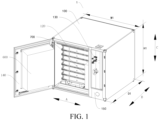
FIG. 1 is a schematic structural diagram of an energy storage battery cabinet according to an embodiment of the disclosure; -
FIG. 2 is a schematic structural diagram of a battery cell layer group having a restraint frame according to an embodiment of the present disclosure. -
FIG. 3 is a partially enlarged view of a region D inFIG. 2 ; -
FIG. 4 is a schematic structural diagram of a battery cell layer group having a restraint band according to an embodiment of the present disclosure. -
FIG. 5 is a partially enlarged view of a region E inFIG. 4 ; -
FIG. 6 is a schematic structural diagram of a restraint frame according to an embodiment of the present disclosure; -
FIG. 7 is a schematic structural diagram of an energy storage system according to an embodiment of the present disclosure; -
FIG. 8 is a schematic structural diagram of an energy storage system with a cabinet door being in a closed state according to an embodiment of the present disclosure; -
FIG. 9 is a schematic structural diagram of an energy storage system with a cabinet door being in an open state according to an embodiment of the present disclosure; -
FIG. 10 is a schematic structural diagram of a cabinet door of an energy storage system according to an embodiment of the present disclosure; and -
FIG. 11 is a schematic structural diagram of a battery cell according to an embodiment of the present disclosure. - In the drawings:
- energy
storage battery cabinet 1,energy storage system 2, -
cabinet body 100,air duct gap 110, heatdissipation air duct 120,wiring compartment 130,first cabinet door 140,second cabinet door 150,third cabinet door 160, - battery
cell layer group 200,battery cell 210, -
restraint frame 220,first side plate 221,second side plate 222, firstbottom plate 223,second bottom plate 224, stopstep 225, -
limit bar 310,limit hole 320,first fastener 330,second fastener 340, -
restraint band 500, pullrod 510, thirdbottom plate 520, fourthbottom plate 530, -
refrigeration unit 600,control unit 700. - The embodiments of the present disclosure are described below in detail. Examples of the embodiments are shown in the accompanying drawings, and same or similar reference signs in all the accompanying drawings indicate same or similar components or components having same or similar functions. The embodiments described below with reference to the accompanying drawings are exemplary, and are merely intended to explain the present disclosure and cannot be construed as a limitation to the present disclosure.
- In the description of the present disclosure, it should be understood that orientation or position relationships indicated by the terms such as "center", "longitudinal", "transverse", "length", "width", "thickness", "on", "below", "front", "back", "left", "right", "vertical", "horizontal", "top", "bottom", "inside", "outside", "clockwise", "anticlockwise", "axial", "radial", and "circumferential" are based on orientation or position relationships shown in the accompanying drawings, and are used only for ease and brevity of illustration and description, rather than indicating or implying that the mentioned apparatus or component needs to have a particular orientation or needs to be constructed and operated in a particular orientation. Therefore, such terms should not be construed as limiting of the present disclosure.
- In the description of the present disclosure, "a number of" means two or more than two, and "several" means one or more.
- An energy
storage battery cabinet 1 according to an embodiment of the present application is described with reference to accompanying drawings. - As shown in
FIG. 1 to FIG. 10 , the energystorage battery cabinet 1 according to this embodiment of the present disclosure includes acabinet body 100 and at least two batterycell layer groups 200. - The
cabinet body 100 has a first direction (a direction indicated by an arrow A), a second direction (a direction indicated by an arrow B), and a third direction (a direction indicated by an arrow C) which are orthogonal to each other. The at least two batterycell layer groups 200 are disposed in thecabinet body 100 and arranged along the third direction. In other words, in the third direction, at least two batterycell layer groups 200 are arranged sequentially. Or, more batterycell layer groups 200 are arranged sequentially along the third direction. In this way, an overall size of the at least two batterycell layer groups 200 in the third direction is closer to the size of thecabinet body 100 in the third direction. The batterycell layer groups 200 can fill up thecabinet body 100 in the third direction. Thecabinet body 100 can accommodate more batterycell layer groups 200. In addition, thecabinet body 100 has the first direction, the second direction, and the third direction which are orthogonal to each other, thecabinet body 100 can be a rectangular paralleloid. In this way, the batterycell layer groups 200 are conveniently accommodated, to cause that the batterycell layer groups 200 can fit or keep a relatively close distance with side walls of thecabinet body 100. A gap between the batterycell layer groups 200 and thecabinet body 100 is prevented from being excessively large, thereby improving the arrangement density of the batterycell layer groups 200 in thecabinet body 100 and improving the volume utilization rate of thebattery cells 210. - Each battery
cell layer group 200 includes at least onebattery cell 210 in each of the first direction and the second direction. For example, each batterycell layer group 200 may be provided withmultiple battery cells 210, and the size of the batterycell layer group 200 in the first direction and the size in the second direction may be adjusted according to a number of thebattery cells 210, to cause that the size of the batterycell layer group 200 in the first direction can be closer to the size of thecabinet body 100 in the first direction, the size of the batterycell layer groups 200 in the second direction can be closer to the size of thecabinet body 100 in the second direction, and thecabinet body 100 can accommodatemore battery cells 210. Moreover, the number ofbattery cells 210 arranged in the batterycell layer group 200 does not affect the size of the batterycell layer group 200 in the third direction, which facilitates arrangement of batterycell layer groups 200, and further improves the volume utilization rate of thebattery cells 210. - Two adjacent battery
cell layer groups 200 in the third direction abut against each other so as to limit each other in the third direction. - The energy
storage battery cabinet 1 can satisfy the use requirements of industrial and commercial energy storage and household energy storage. - According to the energy
storage battery cabinet 1 of this embodiment of the present disclosure, thecabinet body 100 has a first direction, a second direction, and a third direction which are orthogonal to each other. At least two batterycell layer groups 200 are provided in thecabinet body 100 and arranged along the third direction. Each batterycell layer group 200 includes at least onebattery cell 210 in each of the first direction and the second direction. - In other words, the frame in the
cabinet body 100 of the energystorage battery cabinet 1 of the present disclosure is composed of multiple batterycell layer groups 200, and the multiple batterycell layer groups 200 are stacked along the third direction. The number ofbattery cells 210 in each batterycell layer group 200 in the first direction and the second direction is at least 1, to cause that thebattery cells 210 fill up thecabinet body 100 as much as possible, thereby improving the space utilization rate of thecabinet body 100 and achieving a high energy density. - In addition, two adjacent battery
cell layer groups 200 in the third direction are abutted against each other so as to limit each other in the third direction. - In an actual application of the energy
storage battery cabinet 1, the third direction of thecabinet body 100 may be a vertical direction. A bottom surface of each batterycell layer group 200 abuts against a top surface of the batterycell layer group 200 below same. Moreover, under the action of gravity, except for a lowermost batterycell layer group 200, each remaining batterycell layer group 200 is pressed to a lower batterycell layer group 200 adjacent thereto. In this way, the multiple batterycell layer groups 200 are reliably stopped, so that the multiple batterycell layer groups 200 are mutually limited, so as to realize the stable positioning of the multiple batterycell layer groups 200 in thecabinet body 100 and ensure the safety of an electrical connection. - Compared with an energy storage battery cabinet in the related art in which positions of the battery cell layer groups are fixed by arranging a structure such as a bracket or a housing, the energy
storage battery cabinet 1 performs position limit by the multiple batterycell layer groups 200, a limit fastening structure does not need to be additionally provided and the number of parts is reduced, to cause that more space in the energystorage battery cabinet 1 can be left for arranging thebattery cells 210, and to improve the energy density of the energystorage battery cabinet 1 and the volumetric cell to system rate. - In this way, the battery
cell layer groups 200 of the energystorage battery cabinet 1 according to this embodiment of the present disclosure are stacked, to cause that the batterycell layer groups 200 are mutually limited, thereby having advantages of a high energy density, a large volumetric cell to system rate, and the like. - According to some specific embodiments of the present disclosure, as shown in
FIG. 1 andFIG. 3 , the first direction is a width direction of thecabinet body 100, the second direction is a depth direction of thecabinet body 100, and the third direction is a height direction of thecabinet body 100. That is, the multiple batterycell layer groups 200 are arranged along the height direction of thecabinet body 100. In an application of the energystorage battery cabinet 1, the height direction of thecabinet body 100 is generally a vertical direction. Therefore, each batterycell layer group 200 can be installed on thecabinet body 100 or removed from thecabinet body 100 along a horizontal direction, which conforms to the force exertion habit of a human being and is convenient for a user to operate. In addition, each batterycell layer group 200 may abut against a batterycell layer group 200 below same under the action of gravity, so that the abutting between the multiple batterycell layer groups 200 is reliable and the limiting is stable. The lowermost batterycell layer group 200 may abut against thecabinet body 100. In other words, the at least two batterycell layer groups 200 may be in contact with thecabinet body 100 through one side in the third direction. That is, thecabinet body 100 may be directly in contact with one side of the at least two batterycell layer groups 200 located at the lowermost battery cell layer group in thethird direction 200. Further, other batterycell layer groups 200 except for the lowermost batterycell layer groups 200 can be indirectly supported by thecabinet body 100. Therefore, the at least two batterycell layer groups 200 are integrally supported (that is, thecabinet body 100 supports and fastens all of the battery cell layer groups 200), to cause that the arrangement structure of the multiple batterycell layer groups 200 is stable. In short, the batterycell layer groups 200 are stacked and are integrally supported by thecabinet body 100, to cause that the overall position of the multiple batterycell layer groups 200 is kept stable and the multiple batterycell layer groups 200 support each other. Separate configuration of a support structure piece can be omitted, thereby having advantages of a high energy density, a high volumetric cell to system rate, and the like. - According to some specific embodiments of the present disclosure, as shown in
FIG. 1 andFIG. 3 , length directions of thebattery cells 210 are arranged along the first direction, thickness directions of thebattery cells 210 are arranged along the second direction, and width directions of thebattery cells 210 are arranged along the third direction. - The length of each
battery cell 210 is generally greater than the thickness of thebattery cell 210 and the width of thebattery cell 210. By arranging the lengths of thebattery cells 210 along the first direction, the lengths of thebattery cells 210 can be approximately the same as the size of thecabinet body 100 in the first direction, to cause that thebattery cells 210 can fill up thecabinet body 100 in the first direction as much as possible. In addition, the number of thebattery cells 210 in each batterycell layer group 200 arranged in the second direction is determined according to a relationship between the thicknesses of thebattery cells 210 and the size of thecabinet body 100 in the second direction, to further cause that thebattery cells 210 can fill up thecabinet body 100 in the second direction as much as possible. In this way, the volumetric cell to system rate and the energy density of the energystorage battery cabinet 1 can be improved. In addition, the batterycell layer groups 200 are stacked, to cause that the batterycell layer groups 200 are mutually limited, thereby having advantages of a high energy density, a large volumetric cell to system rate, and the like. - According to some specific embodiments of the present disclosure, a number X of the
battery cells 210 in the first direction satisfies: 1 ≤ X ≤ 2. A number Y of thebattery cells 210 in the second direction satisfies: 1 < Y ≤ 26. A number Z of thebattery cells 210 in the third direction satisfies: 1 ≤ Z ≤ 16. - The number of the
battery cells 210 arranged along the first direction may be one or two, to cause that an overall size of thebattery cells 210 in the first direction may be substantially the same as the size of thecabinet body 100 in the first direction and that thebattery cells 210 fill up thecabinet body 100 in the first direction as much as possible. In addition, the number of thebattery cells 210 arranged along the second direction may be 1 to 26, and the overall size of thebattery cells 210 in the second direction may be substantially the same as the size of thecabinet body 100 in the second direction, so that thebattery cells 210 fill up thecabinet body 100 in the first direction as much as possible. In this way, the volumetric cell to system rate and the energy density of the energystorage battery cabinet 1 can be improved. - In addition, the number of the
battery cells 210 arranged in the third direction is not greater than 16, to avoid the situation that the number of thebattery cells 210 arranged in the third direction is excessively large and is not easy to fix. Therefore, the installation stability of thebattery cells 210 is ensured, the electrical connection is also more reliable, and the safety of the energystorage battery cabinet 1 is improved. - According to some specific embodiments of the present disclosure, as shown in
FIG. 1 andFIG. 3 , the length of thebattery cell 210 is L, the thickness of thebattery cell 210 is D, and the width of thebattery cell 210 is H, where (D+H)/L ≤ 0.2. In this way, thebattery cells 210 are of an elongated structure, the structural strength of thebattery cells 210 are high, the amount of electricity stored in thebattery cells 210 are large, the limit by eachbattery cell 210 to another adjacent batterycell layer group 200 is reliable, and the adjacent batterycell layer group 200 can be better supported. - According to some specific embodiments of the present disclosure, as shown in
FIG. 11 , the length of thebattery cell 210 is L, the thickness of thebattery cell 210 is D, and the width of thebattery cell 210 is H, where 400 mm ≤ L ≤ 1200 mm, 10 mm ≤ D ≤ 40 mm, and 60 mm ≤ H ≤ 150 mm. - A household energy
storage battery cabinet 1 generally uses a wall-mounted structure, abattery cell 210 needs to be in a flat form as much as possible, andbattery cells 210 on each batterycell layer group 200 also needs to be in a flat form as much as possible after being arranged. In this way, after the energystorage battery cabinet 1 using theabove battery cells 210 is hung on a wall, the size of a portion protruding from a wall surface is not prone to exceeding 500 mm, so as to hardly interfere with normal activities of a user in the home, and better satisfy the use requirements of home users. - According to some specific embodiments of the present disclosure, as shown in
FIG. 1 andFIG. 3 , the length of thebattery cell 210 is L, the thickness of thebattery cell 210 is D, and the width of thebattery cell 210 is H, where 400 mm ≤ L ≤ 970 mm, 10 mm ≤ D ≤ 30 mm, and 80 mm ≤ H ≤ 130 mm. For example, 800 mm ≤ L ≤ 970 mm, 10 mm ≤ D ≤ 30 mm, and 80 mm ≤ H ≤ 130 mm. - The energy
storage battery cabinet 1 used in industry and commerce generally requires onebattery cell 210 to be arranged in a first direction, andmultiple battery cells 210 can be stacked in a second direction and a third direction. In this way, the energystorage battery cabinet 1 using theabove battery cells 210 has more stored electricity and stronger power supply capacity, which satisfy the use requirements of industry and commerce. - According to some specific embodiments of the present disclosure, as shown in
FIG. 1 andFIG. 11 , the length of thebattery cell 210 is L, the thickness of thebattery cell 210 is D, the width of thebattery cell 210 is H, the width of thecabinet body 100 is W1, the depth of thecabinet body 100 is D1, and the height of thecabinet body 100 is H1, where 0.5 ≤ L/W1 < 1. - For example, the width of the
cabinet body 100 is a distance between outer surfaces of two sides of thecabinet body 100 in the first direction, the depth of thecabinet body 100 is a distance between outer surfaces of two sides of thecabinet body 100 in the second direction, and the height of thecabinet body 100 is a distance between outer surfaces of two sides of thecabinet body 100 in the third direction. - If the length of the
battery cell 210 is half of the width of thecabinet body 100, twobattery cells 210 can be arranged in the width direction of thecabinet body 100. If the length of thebattery cell 210 is greater than half of the width of thecabinet body 100, the length of thebattery cell 210 is closer to the width of the energystorage battery cabinet 1. Therefore thebattery cell 210 can occupy at least half of the space of thecabinet body 100 in the width direction of thecabinet body 100, to cause that the volumetric cell to system rate of the energystorage battery cabinet 1 is large and the energy density is high. - In addition, 0.5 ≤ L/D1 < 1. If the length of the
battery cell 210 is half of the depth of thecabinet body 100, twobattery cells 210 can be arranged in the depth direction of thecabinet body 100. If the length of thebattery cell 210 is greater than half of the depth of thecabinet body 100, the length of thebattery cell 210 is closer to the depth of the energystorage battery cabinet 1. Therefore, thebattery cell 210 can occupy at least more than half of the space of thecabinet body 100 in the depth direction of thecabinet body 100, to cause that the battery cell volume utilization rate of the energystorage battery cabinet 1 is high. - According to some specific embodiments of the present disclosure, as shown in
FIG. 1 andFIG. 3 , the width of thecabinet body 100 is W1, the depth of thecabinet body 100 is D1, and the height of thecabinet body 100 is H1, where 600 mm ≤ W1 ≤ 1200 mm, 700 mm ≤ D1 ≤ 1250 mm, and 600 ≤ H1 ≤ 2600 mm. - In this way, the size of the energy
storage battery cabinet 1 is not excessively large, to cause that the structural strength of the energystorage battery cabinet 1 is ensured, and hoisting is convenient. In addition, the size of the energystorage battery cabinet 1 is not excessively small, to cause that the energystorage battery cabinet 1 has sufficient space for arranging thebattery cells 210, and the power supply duration of the energystorage battery cabinet 1 is prolonged. - According to some specific embodiments of the present disclosure, the
battery cells 210 of two adjacent batterycell layer groups 200 in the third direction abut against each other. In this way, no protection structure needs to be additionally provided between thebattery cells 210, to cause that the number of parts in the energystorage battery cabinet 1, and more space in the energystorage battery cabinet 1 can be left for arranging thebattery cells 210, and to achieve the purpose of improving the volumetric cell to system rate and the energy density of the energystorage battery cabinet 1. - According to some specific embodiments of the present disclosure, as shown in
FIG. 2 to FIG. 4 , anair duct gap 110 is provided between thebattery cells 210 of two adjacent batterycell layer groups 200 in the third direction. In this way, thebattery cells 210 of the two adjacent batterycell layer groups 200 do not directly transfer heat to each other, to cause that heat accumulation between thebattery cells 210 can be avoided, thebattery cells 210 of each batterycell layer group 200 and the energystorage battery cabinet 1 have a larger air heat exchange area, and the heat dissipation capability of thebattery cells 210 is improved. - According to some specific embodiments of the present disclosure, as shown in
FIG. 2 to FIG. 4 , a size of theair duct gap 110 in the third direction ranges from 5 mm to 20 mm. In this way, the distance between thebattery cells 210 the two batterycell layer groups 200 is not less than 5 mm, which can facilitate sufficient heat dissipation of thebattery cells 210 in each batterycell layer group 200 and avoid thermal runaway caused by heat accumulation. In addition, the distance between thebattery cells 210 of the two batterycell layer groups 200 is not greater than 16 mm, to cause that the volumetric cell to system rate and the energy density of the energystorage battery cabinet 1 are ensured. - According to some specific embodiments of the present disclosure, as shown in
FIG. 2 to FIG. 4 , the number of the batterycell layer groups 200 ranges from 2 to 18. The batterycell layer groups 200 need to support each other, and therefore during use of the energystorage battery cabinet 1, one of two outermost batterycell layer groups 200 needs to bear the pressure of the other batterycell layer group 200. Therefore, by setting the number of the batterycell layer groups 200 to be not greater than 18, the outermost batterycell layer groups 200 can be prevented from being broken by pressure, to cause that the service life of each batterycell layer group 200 is ensured. In addition, the number of batterycell layer groups 200 is not less than two, to cause that the volumetric cell to system rate of the energystorage battery cabinet 1 is increased and the power supply duration of energystorage battery cabinet 1 is prolonged. - According to some embodiments of the present disclosure, as shown in
FIG. 2 andFIG. 4 , the at least two batterycell layer groups 200 arranged in the third direction define an overall width of W2, an overall depth of D2, and an overall height of H2, where 500 mm ≤ W2 ≤ 1100 mm, 450 mm ≤ D2 ≤ 1000 mm, and 450 mm ≤ H2 ≤ 2450 mm. - In this way, on one hand, the overall size of the multiple battery
cell layer groups 200 is not excessively large, to cause that the batterycell layer groups 200 are suitable for different usage scenarios, and the energystorage battery cabinet 1 using the multiple batterycell layer groups 200 of the present disclosure is also easy to move and disassemble. On the other hand, the overall size of the multiple batterycell layer groups 200 is not excessively small, to cause that the power stored in the multiple batterycell layer groups 200 can satisfy the use in most situations and the endurance is strong. - According to some specific embodiments of the present disclosure, as shown in
FIG. 4 to FIG. 6 , each batterycell layer group 200 further includes arestraint frame 220, thebattery cells 210 in each batterycell layer group 200 are arranged on therestraint frame 220, and the restraint frames 220 of two adjacent batterycell layer groups 200 in the third direction abut against each other. - By configuring the
restraint frame 220,multiple battery cells 210 can be fastened using therestraint frame 220, to cause that the structural strength of therestraint frame 220 can be used to assist in improving the structural strength of thebattery cells 210. Therefore, the number of batterycell layer groups 200 that can be arranged in the energystorage battery cabinet 1 can be more. For example, the number of batterycell layer groups 200 may be 15, 16, 17, 18, 19, or 20. With such the design, the volumetric cell to system rate of the energystorage battery cabinet 1 is large and the energy density is high. - According to some embodiments of the present disclosure, as shown in
FIG. 4 to FIG. 6 , therestraint frame 220 includes afirst bottom plate 223 and asecond bottom plate 224. Thefirst bottom plate 223 and thesecond bottom plate 224 are arranged spaced away along one of the first direction and the second direction. Two ends of thebattery cells 210 in the length direction are respectively supported on thefirst bottom plate 223 and thesecond bottom plate 224. An air duct gap is formed between thefirst bottom plate 223 and thesecond bottom plate 224. - Through the arrangement of the
first bottom plate 223 and thesecond bottom plate 224, thebattery cells 210 can be supported. Thefirst bottom plate 223 and thesecond bottom plate 224 can guide a gas that enters theair duct gap 110, to improve the heat dissipation efficiency of the gas for thebattery cells 210, to cause that thebattery cells 210 are less likely to be damaged by heat and the service life of the energystorage battery cabinet 1 is prolonged. In addition, stopsteps 225 may be formed on an upper surface of thefirst bottom plate 223 and an upper surface of thesecond bottom plate 224, for limiting thebattery cells 210 between thefirst bottom plate 223 and thesecond bottom plate 224. - According to some specific embodiments of the present disclosure, as shown in
FIG. 4 to FIG. 6 , therestraint frame 220 further includes afirst side plate 221 and asecond side plate 222. Thefirst side plate 221 and thesecond side plate 222 are respectively located at two sides of the batterycell layer group 200. Thefirst side plate 221 and thesecond side plate 222 are oppositely arranged in the other direction of the first direction and the second direction. Two ends of thefirst bottom plate 223 are respectively connected to one end of thefirst side plate 221 and one end of thesecond side plate 222. Two ends of thesecond bottom plate 224 are respectively connected to the other end of thefirst side plate 221 and the other end of thesecond side plate 222. For the two adjacent batterycell layer groups 200 in the third direction, thefirst bottom plate 223 of one batterycell layer group 200 abuts against thefirst side plate 221 and thesecond side plate 222 of the other batterycell layer group 200, and thesecond bottom plate 224 of the one batterycell layer group 200 abuts against thefirst side plate 221 and thesecond side plate 222 of the other batterycell layer group 200. - In this way, two adjacent battery
cell layer groups 200 do not need to directly abut against thebattery cells 210, to cause that the probability that thebattery cell 210 is broken by force is reduced. In addition, thefirst side plate 221 and thesecond side plate 222 are located at two opposite sides of the batterycell layer group 200, to cause that the two adjacent batterycell layer groups 200 can be prevented from being deflected by force and the arrangement of the batterycell layer groups 200 is more stable. - According to some specific embodiments of the present disclosure, as shown in
FIG. 4 to FIG. 6 , each of thefirst bottom plate 223 and thesecond bottom plate 224 is provided with one of alimit bar 310 and alimit hole 320 and each of thefirst side plate 221 and thesecond side plate 222 is provided with the other one of thelimit bar 310 and thelimit hole 320. For two adjacent batterycell layer groups 200 in the third direction, thelimit bar 310 of one batterycell layer group 200 is matched with thelimit hole 320 of the other batterycell layer group 200. - Through the coordination between the
limit hole 320 and thelimit bar 310, the position between the adjacent batterycell layer groups 200 can be fixed, and relative rotation between the adjacent batterycell layer groups 200 can be prevented. The positioning accuracy is high, the assembly and electrical connection are more reliable, and the safety is high. - According to some specific embodiments of the present disclosure, as shown in
FIG. 4 to FIG. 6 , either the limit bars 310 or the limit holes 320 are distributed at two ends of thefirst bottom plate 223 and two ends of thesecond bottom plate 224, and the other one of the limit bars 310 and the limit holes 320 are distributed at two ends of thefirst side plate 221 and two ends of thesecond side plate 222. - In this way, more fixing points are provided between the adjacent battery
cell layer groups 200, to further improve the positioning accuracy between the adjacent batterycell layer groups 200. The assembly and electrical connection is more reliable and a high safety is achieved. - According to some specific embodiments of the present disclosure, as shown in
FIG. 4 to FIG. 6 , for the two adjacent batterycell layer groups 200 in the third direction, thefirst side plate 221 of the other batterycell layer group 200 is fastened to thefirst bottom plate 223 and thesecond bottom plate 224 of one batterycell layer group 200 by thefirst fastener 330, thesecond side plate 222 of the other batterycell layer group 200 is fastened to thefirst bottom plate 223 and thesecond bottom plate 224 of the one batterycell layer group 200 by asecond fastener 340. Thefirst fastener 330 and thesecond fastener 340 may be threaded fasteners. - In this way, the relative position between the adjacent battery
cell layer groups 200 can be locked, and separation between the adjacent batterycell layer groups 200 can be prevented in a transportation or assembly process. Therefore, the adjacent batterycell layer groups 200 can be integrally disassembled and assembled. Not only a high assembly efficiency is achieved, but also the positioning accuracy between the adjacent batterycell layer groups 200 in the entire transportation and assembly process can be ensured. Therefore, the overall assembly accuracy of the energystorage battery cabinet 1 is high, the assembly and electrical connection are more reliable, and the safety is high. - According to some specific embodiments of the present disclosure, as shown in
FIG. 4 to FIG. 6 , thefirst fasteners 330 are distributed at two ends of thefirst side plate 221, and thesecond fasteners 340 are distributed at two ends of thesecond side plate 222. - In this way, multiple fixing points are provided between the relative positions of the adjacent battery
cell layer groups 200, the adjacent batterycell layer groups 200 are less likely to be separated, and the positioning accuracy between the adjacent batterycell layer groups 200 can be more reliably ensured. Therefore, the overall assembly accuracy of the energystorage battery cabinet 1 is high, the assembly and electrical connection are more reliable, and the safety is high. - According to some specific embodiments of the present disclosure, as shown in
FIG. 4 to FIG. 6 , the volume of eachbattery cell 210 is V1, the number of thebattery cells 210 is N, and the volume of thecabinet body 100 is V3, where 35% < (N*V1)/V3 ≤ 50%. A space in thecabinet body 100 other than the space occupied by thebattery cells 210 can be configured for arranging units such as acontrol unit 700, arestraint frame 220, arefrigeration unit 600, and a fire fighting unit. - In this way, a sufficient space is left for arranging other units while the volumetric cell to system rate of the energy
storage battery cabinet 1 is increased. The space of the energystorage battery cabinet 1 is more fully utilized, and the volume of the energystorage battery cabinet 1 does not need to be set excessively large, to cause that the energystorage battery cabinet 1 can be conveniently applied to different scenes. - According to some specific embodiments of the present disclosure, as shown in
FIG. 2 andFIG. 3 , each batterycell layer group 200 further includes a thirdbottom plate 520 and afourth bottom plate 530. The thirdbottom plate 520 and thefourth bottom plate 530 are arranged spaced away along one of the first direction and the second direction. For two adjacent batterycell layer groups 200 in the third direction, the thirdbottom plate 520 and thefourth bottom plate 530 of one batterycell layer group 200 abut against thebattery cells 210 of the other batterycell layer group 200. Anair duct gap 110 is formed between the thirdbottom plate 520 and thefourth bottom plate 530. - In this way, two adjacent battery
cell layer groups 200 do not need to directly abut against thebattery cells 210, to cause that the probability that abattery cell 210 is broken by force is reduced. In addition, the thirdbottom plate 520 and thefourth bottom plate 530 are located at two opposite sides of the batterycell layer group 200, to cause that the two adjacent batterycell layer groups 200 can be prevented from being deflected by force and the arrangement of the batterycell layer groups 200 is more stable. - According to some specific embodiments of the present disclosure, as shown in
FIG. 2 andFIG. 3 , at least onerestraint band 500 is provided on one side of the at least two batterycell layer groups 200 in the third direction, two ends of eachrestraint band 500 are respectively connected to pullrods 510, and each pullrod 510 and thecabinet body 100 are connected to the other side of the at least two batterycell layer groups 200 in the third direction. - The
pull rods 510 may extend in the third direction and thepull rods 510 are located at two sides of the batterycell layer group 200 in the first direction or the second direction. In other words, if thepull rods 510 are located at two sides of the batterycell layer group 200 in the first direction, therestraint band 500 may extend in the first direction, and thepull rods 510 can fasten and limit the batterycell layer group 200 in the first direction. If thepull rods 510 are located at two sides of the batterycell layer group 200 in the second direction, therestraint band 500 may extend in the second direction, and thepull rods 510 can fasten and limit the batterycell layer group 200 in the second direction. - Certainly, the number of the
restraint bands 500 may be more than one. Onerestraint band 500 may extend along the first direction, and thepull rods 510 connected to the restraint band are located at two sides of the batterycell layer group 200 in the first direction. Theother restraint band 500 may extend along the second direction, and thepull rods 510 connected to the restraint band are located at two sides of the batterycell layer group 200 in the second direction. In this way, thepull rods 510 can simultaneously fasten and limit the batterycell layer group 200 in the first direction and the second direction. - In addition, through the coordination between the
restraint band 500 and thepull rod 510, the batterycell layer group 200 can be fixed and limited in the third direction, the position of the batterycell layer group 200 is not susceptible to change, the electrical connection reliability of thebattery cells 210 is ensured, and the safety and structural stability of the energystorage battery cabinet 1 are improved. In addition, no fastening structures need to be additionally provided between the at least two batterycell layer groups 200. Therefore, a large space in the energystorage battery cabinet 1 is left for arranging the batterycell layer groups 200. The volumetric cell to system rate can be greatly increased. - According to some specific embodiments of the present disclosure, as shown in
FIG. 2 andFIG. 3 , the volume of eachbattery cell 210 is V1, the number of thebattery cells 210 is N, and the volume of thecabinet body 100 is V3, where 35% < (N*V1)/V3 ≤ 50%. A space in thecabinet body 100 other than the space occupied by thebattery cells 210 can be configured for arranging units such as acontrol unit 700, arefrigeration unit 600, and a fire fighting unit. - In this way, a sufficient space is left for arranging other units while the volumetric cell to system rate and the energy density of the energy
storage battery cabinet 1 is increased. The space of the energystorage battery cabinet 1 is more fully utilized, and the volume of the energystorage battery cabinet 1 does not need to be set excessively large, to cause that the energystorage battery cabinet 1 can be conveniently applied to different scenes. - According to some specific embodiments of the present disclosure, as shown in
FIG. 1 , the energystorage battery cabinet 1 further includes arefrigeration unit 600. Therefrigeration unit 600 is installed in thecabinet body 100 and located at a side of thecabinet body 100 in the second direction. Therefrigeration unit 600 is provided with an air outlet and a return air inlet. A heatdissipation air duct 120 communicated with the air outlet is provided on one side of thecabinet body 100 in the third direction. Anair duct gap 110 is provided between thebattery cells 210 of the two adjacent batterycell layer groups 200 in the third direction. An airflow flows into the heatdissipation air duct 120 from the air outlet, then flows through the at least two batterycell layer groups 200 from the other side in the second direction and the two sides in the first direction, and flows to the return air inlet through theair duct gap 110. - By providing the
refrigeration unit 600, a gas in the energystorage battery cabinet 1 is driven to circulate, to cause exchange heat with the gas in the energystorage battery cabinet 1 and reduce the temperature of the gas in the energystorage battery cabinet 1. Therefore, a gas in the low-temperature energystorage battery cabinet 1 can cool and dissipate thebattery cells 210 in the energystorage battery cabinet 1. Thermal runaway caused by heat accumulation of thebattery cells 210 in the energystorage battery cabinet 1 can be avoided and the safety of the energystorage battery cabinet 1 is improved. - The
air duct gap 110 is provided between thebattery cells 210 of the two adjacent batterycell layer groups 200, the heat exchange area between the gas in the energystorage battery cabinet 1 and eachbattery cell 210 is large, and the heat exchange efficiency is improved. In addition, therefrigeration unit 600 is located at one side of thecabinet body 100 in the second direction. Therefore, therefrigeration unit 600 does not affect the arrangement of the batterycell layer groups 200 along the third direction. The number of the batterycell layer groups 200 can be more, to cause that the number of thebattery cells 210 can also be more, so as to improve the volumetric cell to system rate of the energystorage battery cabinet 1. - According to some specific embodiments of the present disclosure, as shown in
FIG. 1 andFIG. 9 , thecabinet body 100 in the second direction is provided with awiring compartment 130, afirst cabinet door 140, and asecond cabinet door 150 on one side of the cabinet body along the second direction, and thecabinet body 100 is provided with athird cabinet door 160 on one side of the cabinet body in the second direction. The energystorage battery cabinet 1 further includes arefrigeration unit 600 and acontrol unit 700. Both therefrigeration unit 600 and thecontrol unit 700 are installed in thecabinet body 100. Therefrigeration unit 600 is installed on thefirst cabinet door 140. Thecontrol unit 700 is exposed by opening thefirst cabinet door 140, thesecond cabinet door 150 is configured to open and close thewiring compartment 130. At least two batterycell layer groups 200 are put in or taken out from thecabinet body 100 by opening thethird cabinet door 160. - In this way, a headroom size in the energy
storage battery cabinet 1 can be used to an extreme extent, the volumetric cell to system rate in the energystorage battery cabinet 1 can be improved, and the disassembly and assembly between therefrigeration unit 600, thecontrol unit 700, and the batterycell layer group 200 are not easy to interfere, to cause that the production, maintenance, and replacement are more convenient. - According to some specific embodiments of the present disclosure, as shown in
FIG. 1 , thefirst cabinet door 140 and thesecond cabinet door 150 are arranged along the first direction, and therefrigeration unit 600 and thecontrol unit 700 are arranged along the first direction. In this way, the batterycell layer groups 200 are arranged along the third direction. Therefore, in an actual application, the third direction of the energystorage battery cabinet 1 is generally a vertical direction. By arranging thefirst cabinet door 140 and thesecond cabinet door 150 along the first direction, that is, both thefirst cabinet door 140 and thesecond cabinet door 150 extending along the third direction, to cause that opening and closing by a user are convenient and subsequent maintenance and overhaul are facilitated. - An
energy storage system 2 according to an embodiment of the present disclosure is described below with reference to the accompanying drawings. As shown inFIG. 8 to FIG. 10 , theenergy storage system 2 includes at least one energystorage battery cabinet 1 according to an embodiment of the present disclosure. - According to the
energy storage system 2 of the embodiment of the present disclosure, by using the energystorage battery cabinet 1 according to the embodiment of the present disclosure, the batterycell layer groups 200 are stacked, to cause that the batterycell layer groups 200 are mutually limited, thereby having advantages of a high energy density, a large volumetric cell to system rate, and the like. - Other compositions and operations of the energy
storage battery cabinet 1 and theenergy storage system 2 having same according to the embodiments of the present disclosure are known to those of ordinary skill in the art, and are not described herein again in detail. - In the description of this specification, description of reference terms such as "a specific embodiment" or "a specific example", means including specific features, structures, materials, or features described in the embodiment or example in at least one embodiment or example of the present disclosure. In this specification, exemplary descriptions of the foregoing terms do not necessarily refer to the same embodiment or example.
- Although the embodiments of the present disclosure have been shown and described, a person of ordinary skill in the art should understand that various changes, modifications, replacements and variations may be made to the embodiments without departing from the principles and spirit of the present disclosure, and the scope of the present disclosure is as defined by the appended claims and their equivalents.
Claims (27)
- An energy storage battery cabinet (1), comprising:a cabinet body (100), the cabinet body (100) having a first direction, a second direction, and a third direction which are orthogonal to each other; andat least two battery cell layer groups (200), the at least two battery cell layer groups (200) being provided in the cabinet body (100) and arranged along the third direction, each battery cell layer group (200) comprising at least one battery cell (210) in each direction of the first direction and the second direction, and two adjacent battery cell layer groups (200) in the third direction abutting against each other so as to limit each other in the third direction.
- The energy storage battery cabinet (1) according to claim 1, wherein the at least two battery cell layer groups (200) are integrally supported by being in contact with the cabinet body (100) at one side in the third direction.
- The energy storage battery cabinet (1) according to claim 1 or 2, wherein the first direction is a width direction of the cabinet body (100), the second direction is a depth direction of the cabinet body (100), and the third direction is a height direction of the cabinet body (100).
- The energy storage battery cabinet (1) according to any one of claims 1 to 3, wherein length directions of the battery cells (210) are arranged along the first direction, thickness directions of the battery cells (210) are arranged along the second direction, and width directions of the battery cells (210) are arranged along the third direction.
- The energy storage battery cabinet (1) according to any one of claims 1 to 4, wherein a number Z of the battery cells (210) arranged in the first direction satisfies: 1 ≤ X ≤ 2;a number Y of the battery cells (210) arranged in the second direction satisfies: 1 < Y ≤ 26; anda number Z of the battery cells (210) arranged in the third direction satisfies: 1 ≤ Z ≤ 16.
- The energy storage battery cabinet (1) according to any one of claims 1 to 5, wherein a length of each battery cell (210) is L, a thickness of the battery cell (210) is D, and a width of the battery cell (210) is H, wherein (D+H)/L ≤ 0.2.
- The energy storage battery cabinet (1) according to any one of claims 1 to 6, wherein the length of each battery cell (210) is L, the thickness of the battery cell (210) is D, and the width of the battery cell (210) is H, wherein 400 mm ≤ L ≤ 1200 mm, 10 mm ≤ D ≤ 40 mm, and 60 mm ≤ H ≤ 150 mm.
- The energy storage battery cabinet (1) according to any one of claims 1 to 7, wherein the length of each battery cell (210) is L, the thickness of the battery cell (210) is D, and the width of the battery cell (210) is H; andthe width of the cabinet body (100) is W1, the depth of the cabinet body (100) is D1, and the height of the cabinet body (100) is H1,wherein 0.5 ≤ L/W1 < 1; and/or 0.5 ≤ L/D1 < 1.
- The energy storage battery cabinet (1) according to any one of claims 1 to 8, wherein the width of the cabinet body (100) is W1, the depth of the cabinet body (100) is D1, and the height of the cabinet body (100) is H1, wherein 600 mm ≤ W1 ≤ 1200 mm, 700 mm ≤ D1 ≤ 1250 mm, and 600 ≤ H1 ≤ 2600 mm.
- The energy storage battery cabinet (1) according to any one of claims 1 to 9, wherein an air duct gap (110) is provided between the battery cells (210) of the two adjacent battery cell layer groups (200) in the third direction.
- The energy storage battery cabinet (1) according to claim 10, wherein a size of the air duct gap (110) in the third direction ranges from 5 mm to 20 mm.
- The energy storage battery cabinet (1) according to any one of claims 1 to 11, wherein a number of the battery cell layer groups (200) ranges from 2 to 18.
- The energy storage battery cabinet (1) according to any one of claims 1 to 12, wherein the at least two battery cell layer groups (200) arranged in the third direction define an overall width of W2, an overall depth of D2, and an overall height of H2, wherein 500 mm ≤ W2 ≤ 1100 mm, 450 mm ≤ D2 ≤ 1000 mm, and 450 mm ≤ H2 ≤ 2450 mm.
- The energy storage battery cabinet (1) according to any one of claims 1 to 9, wherein battery cells (210) of the two adjacent battery cell layer groups (200) in the third direction abut against each other.
- The energy storage battery cabinet (1) according to any one of claims 1 to 13, wherein each battery cell layer group (200) further comprises:
a restraint frame (220), battery cells (210) in each battery cell layer groups (200) are arranged in the restraint frame (220), restraint frames (220) of the two adjacent battery cell layer groups (200) in the third direction abut against each other. - The energy storage battery cabinet (1) according to claim 15, wherein the restraint frame (220) comprises:a first bottom plate (223); anda second bottom plate (224), the second bottom plate (224) and the first bottom plate (223) being arranged spaced away along one of the first direction and the second direction, two ends of the battery cells in the length direction being respectively supported on the first bottom plate (223) and the second bottom plate (224), and an air duct gap (110) being formed between the first bottom plate (223) and the second bottom plate (224).
- The energy storage battery cabinet (1) according to claim 16, wherein the restraint frame (220) further comprises:a first side plate (221); anda second side plate (222), the second side plate (222) and the first side plate (221) being respectively located at two sides of the battery cell layer group (200), the first side plate (221) and the second side plate (222) being arranged opposite to each other in the first direction and the second direction, two ends of the first bottom plate (223) being respectively connected to one end of the first side plate (221) and one end of the second side plate (222), and two ends of the second bottom plate (224) being respectively connected to the other end of the first side plate (221) and the other end of the second side plate (222),wherein for two adjacent battery cell layer groups (200) in the third direction, the first bottom plate (223) of one battery cell layer group (200) abuts against the first side plate (221) and the second side plate (222) of the other battery cell layer group (200), and the second bottom plate (224) of the one battery cell layer group (200) abuts against the first side plate (221) and the second side plate (222) of the other battery cell layer group (200).
- The energy storage battery cabinet (1) according to claim 17, wherein each of the first bottom plate (223) and the second bottom plate (224) is provided with one of a limit bar (310) and a limit hole (320) and each of the first side plate (221) and the second side plate (222) is provided with the other one of the limit bar (310) and the limit hole (320), wherein for the two adjacent battery cell layer groups (200) in the third direction, the limit bar (310) of one battery cell layer group (200) is matched with the limit hole (320) of the other battery cell layer group (200).
- The energy storage battery cabinet (1) according to claim 18, wherein either the limit bars (310) or the limit holes (320) are distributed at two ends of the first bottom plate (223) and two ends of the second bottom plate (224); and
the other one of the limit bars (310) and the limit holes (320) are distributed at two ends of the first side plate (221) and two ends of the second side plate (222). - The energy storage battery cabinet (1) according to any one of claims 17 to 19, wherein for two adjacent battery cell layer groups (200) in the third direction, the first side plate (221) of the other battery cell layer group (200) is fastened to the first bottom plate (223) and the second bottom plate (224) of the one battery cell layer group (200) by first fasteners (330), and the second side plate (222) of the other battery cell layer group (200) is fastened to the first bottom plate (223) and the second bottom plate (224) of the one battery cell layer group (200) by second fasteners (340).
- The energy storage battery cabinet (1) according to claim 20, wherein the first fasteners (330) are distributed at two ends of the first side plate (221), and the second fasteners (340) are distributed at two ends of the second side plate (222).
- The energy storage battery cabinet (1) according to any one of claims 1 to 21, wherein a volume of each battery cell (210) is V1, a number of the battery cells (210) is N, and a volume of the cabinet body (100) is V3, wherein 35% < (N*V1)/V3 ≤ 50%.
- The energy storage battery cabinet (1) according to any one of claims 1 to 22, wherein each battery cell layer group (200) further comprises:a third bottom plate (520); anda fourth bottom plate (530), the fourth bottom plate (530) and the third bottom plate (520) being arranged spaced away along one of the first direction and the second direction, for the two adjacent battery cell layer groups (200) in the third direction, the third bottom plate (520) and the fourth bottom plate (530) of one of the battery cell layer groups (200) abutting against battery cells of the other battery cell layer group (200), and an air duct gap (110) being formed between the third bottom plate (520) and the fourth bottom plate (530).
- The energy storage battery cabinet (1) according to claim 23, wherein at least one restraint band (500) is provided on one side of the at least two battery cell layer groups (200) in the third direction, two ends of each restraint band (500) are respectively connected to pull rods (510), and each pull rod (510) and the cabinet body (100) are connected to the other side of the at least two battery cell layer groups (200) in the third direction.
- The energy storage battery cabinet (1) according to any one of claims 1 to 24, further comprising:a refrigeration unit (600), the refrigeration unit (600) being installed in the cabinet body (100) and located at one side of the cabinet body (100) in the second direction, the refrigeration unit (600) being provided with an air outlet and a return air inlet, a side of the cabinet body (100) in the third direction being configured with a heat dissipation air duct (120) communicated with the air outlet, and an air duct gap (110) being provided between the battery cells (210) of two adjacent battery cell layer groups (200) in the third direction,wherein an airflow flows into the heat dissipation air duct (120) from the air outlet, then flows through the at least two battery cell layer groups (200) from the other side in the second direction and two sides in the first direction, and flows to the return air inlet through the air duct gap (110).
- The energy storage battery cabinet (1) according to any one of claims 1 to 25, wherein the cabinet body (100) is provided with a wiring compartment (130), a first cabinet door (140), and a second cabinet door (150) on one side in the second direction, and the cabinet body (100) is provided with a third cabinet door (160) on the other side in the second direction; andthe energy storage battery cabinet (1) further comprises a refrigeration unit (600) and a control unit (700), and both the refrigeration unit (600) and the control unit (700) are installed in the cabinet body (100),wherein the refrigeration unit (600) is installed on the first cabinet door (140), the control unit (700) is exposed by opening the first cabinet door (140), the second cabinet door (150) is configured to open and close the wiring compartment (130), and the at least two battery cell layer groups (200) are put in or taken out from the cabinet body (100) by opening the third cabinet door (160); andthe first cabinet door (140) and the second cabinet door (150) are arranged along the first direction, and the refrigeration unit (600) and the control unit (700) are arranged along the first direction.
- An energy storage system (2), comprising at least one energy storage battery cabinet (1) according to any one of claims 1 to 26.
Applications Claiming Priority (3)
| Application Number | Priority Date | Filing Date | Title |
|---|---|---|---|
| CN202210833929.7A CN117438730B (en) | 2022-07-15 | 2022-07-15 | Energy storage battery cabinet and energy storage system having the same |
| CN202221841014.2U CN218242075U (en) | 2022-07-15 | 2022-07-15 | Energy storage battery cabinet and energy storage system with same |
| PCT/CN2023/098232 WO2024012090A1 (en) | 2022-07-15 | 2023-06-05 | Energe storage battery cabinet and energy storage system having same |
Publications (2)
| Publication Number | Publication Date |
|---|---|
| EP4550545A1 true EP4550545A1 (en) | 2025-05-07 |
| EP4550545A4 EP4550545A4 (en) | 2026-04-01 |
Family
ID=89535411
Family Applications (1)
| Application Number | Title | Priority Date | Filing Date |
|---|---|---|---|
| EP23838584.3A Pending EP4550545A4 (en) | 2022-07-15 | 2023-06-05 | ENERGY STORAGE BATTERY CABINET AND ENERGY STORAGE SYSTEM WITH THIS |
Country Status (6)
| Country | Link |
|---|---|
| US (1) | US20260121196A1 (en) |
| EP (1) | EP4550545A4 (en) |
| AU (1) | AU2023308107A1 (en) |
| CL (1) | CL2025000117A1 (en) |
| WO (1) | WO2024012090A1 (en) |
| ZA (1) | ZA202500655B (en) |
Families Citing this family (1)
| Publication number | Priority date | Publication date | Assignee | Title |
|---|---|---|---|---|
| CN121100439A (en) * | 2024-06-25 | 2025-12-09 | 微宏动力系统(湖州)有限公司 | Support assembly, battery cell assembly and battery cell module |
Family Cites Families (12)
| Publication number | Priority date | Publication date | Assignee | Title |
|---|---|---|---|---|
| JPH0785847A (en) * | 1993-09-17 | 1995-03-31 | Matsushita Electric Ind Co Ltd | Sealed alkaline storage battery unit cell and battery system |
| CN202189849U (en) * | 2011-09-06 | 2012-04-11 | 宁波格澜特电器有限公司 | Floor type battery pack group |
| KR102580847B1 (en) * | 2018-04-26 | 2023-09-19 | 에스케이온 주식회사 | Battery Rack |
| KR102743901B1 (en) * | 2019-06-05 | 2024-12-16 | 주식회사 엘지에너지솔루션 | Battery rack and energy storage system comprising the same |
| CN111162220A (en) * | 2020-01-20 | 2020-05-15 | 威睿电动汽车技术(宁波)有限公司 | A stacked battery system |
| KR102803017B1 (en) * | 2020-03-05 | 2025-05-02 | 주식회사 엘지에너지솔루션 | A battery pack having a structure in which cooling water can be introduced into the battery module when a thermal runaway occurs and Energy storage system comprising the same |
| CN211320187U (en) * | 2020-03-18 | 2020-08-21 | 江苏大秦新能源科技有限公司 | Stacked battery energy storage system |
| CN111883712B (en) * | 2020-08-14 | 2024-10-25 | 傲普(上海)新能源有限公司 | Energy storage battery cabinet |
| CN214706075U (en) * | 2021-03-24 | 2021-11-12 | 远景动力技术(江苏)有限公司 | Energy storage device |
| CN113410565A (en) * | 2021-06-15 | 2021-09-17 | 傲普(上海)新能源有限公司 | Simplified installation method of energy storage battery |
| CN114678644B (en) * | 2021-11-25 | 2024-07-19 | 东莞新能安科技有限公司 | Battery pack and energy storage system |
| CN218242075U (en) * | 2022-07-15 | 2023-01-06 | 比亚迪股份有限公司 | Energy storage battery cabinet and energy storage system with same |
-
2023
- 2023-06-05 WO PCT/CN2023/098232 patent/WO2024012090A1/en not_active Ceased
- 2023-06-05 EP EP23838584.3A patent/EP4550545A4/en active Pending
- 2023-06-05 AU AU2023308107A patent/AU2023308107A1/en active Pending
-
2025
- 2025-01-02 US US19/008,304 patent/US20260121196A1/en active Pending
- 2025-01-15 CL CL2025000117A patent/CL2025000117A1/en unknown
- 2025-01-20 ZA ZA2025/00655A patent/ZA202500655B/en unknown
Also Published As
| Publication number | Publication date |
|---|---|
| ZA202500655B (en) | 2025-08-27 |
| US20260121196A1 (en) | 2026-04-30 |
| WO2024012090A1 (en) | 2024-01-18 |
| CL2025000117A1 (en) | 2025-03-28 |
| EP4550545A4 (en) | 2026-04-01 |
| AU2023308107A1 (en) | 2025-01-30 |
Similar Documents
| Publication | Publication Date | Title |
|---|---|---|
| US12573673B2 (en) | Battery charge and discharge test apparatus | |
| US20130052491A1 (en) | Thermal management system for a multi-cell array | |
| CN218242075U (en) | Energy storage battery cabinet and energy storage system with same | |
| CN211789153U (en) | An energy storage container | |
| CN215451598U (en) | Battery pack shell and battery pack | |
| CN117438707A (en) | Energy storage battery cabinet and energy storage system with same | |
| US20260121196A1 (en) | Energy storage battery cabinet and energy storage system having same | |
| CN111883712A (en) | Energy storage battery cabinet | |
| US20250158192A1 (en) | Energy storage battery cabinet and energy storage system having same | |
| CN218182320U (en) | Air-cooled energy storage battery | |
| CN210379343U (en) | Battery PACK cooling module and energy storage container | |
| WO2024164444A1 (en) | Battery formation and capacity grading device | |
| CN216213690U (en) | Battery heat radiation structure, battery box and battery structure | |
| CN110323387B (en) | Battery box | |
| CN220155642U (en) | Energy storage battery cabinet | |
| CN219843031U (en) | Battery pack shell, battery pack and electric equipment | |
| CN114464918B (en) | Battery pack | |
| CN117277102A (en) | Outdoor all-in-one air-cooled energy storage cabinet | |
| CN117438730B (en) | Energy storage battery cabinet and energy storage system having the same | |
| CN223612478U (en) | A battery and an electrical device | |
| US20150037630A1 (en) | Storage battery cabinet and storage battery system | |
| CN221783300U (en) | A heat dissipation mechanism for a battery cabinet for electric ships | |
| CN117996274B (en) | Energy storage system with air-cooled air duct structure | |
| CN223956632U (en) | Battery module with heat dissipation channel | |
| CN219226387U (en) | Energy storage battery cabinet convenient to heat dissipation |
Legal Events
| Date | Code | Title | Description |
|---|---|---|---|
| STAA | Information on the status of an ep patent application or granted ep patent |
Free format text: STATUS: THE INTERNATIONAL PUBLICATION HAS BEEN MADE |
|
| PUAI | Public reference made under article 153(3) epc to a published international application that has entered the european phase |
Free format text: ORIGINAL CODE: 0009012 |
|
| STAA | Information on the status of an ep patent application or granted ep patent |
Free format text: STATUS: REQUEST FOR EXAMINATION WAS MADE |
|
| 17P | Request for examination filed |
Effective date: 20250203 |
|
| AK | Designated contracting states |
Kind code of ref document: A1 Designated state(s): AL AT BE BG CH CY CZ DE DK EE ES FI FR GB GR HR HU IE IS IT LI LT LU LV MC ME MK MT NL NO PL PT RO RS SE SI SK SM TR |
|
| DAV | Request for validation of the european patent (deleted) | ||
| DAX | Request for extension of the european patent (deleted) | ||
| RIC1 | Information provided on ipc code assigned before grant |
Ipc: H01M 50/244 20210101AFI20251202BHEP Ipc: H01M 50/209 20210101ALI20251202BHEP Ipc: H01M 50/233 20210101ALI20251202BHEP Ipc: H01M 50/103 20210101ALI20251202BHEP Ipc: H01M 50/289 20210101ALI20251202BHEP Ipc: H01M 10/613 20140101ALI20251202BHEP Ipc: H01M 10/627 20140101ALI20251202BHEP Ipc: H01M 10/6561 20140101ALI20251202BHEP Ipc: H01M 10/663 20140101ALI20251202BHEP Ipc: H01M 50/211 20210101ALI20251202BHEP Ipc: H01M 50/251 20210101ALI20251202BHEP Ipc: H01M 50/258 20210101ALI20251202BHEP Ipc: H01M 50/262 20210101ALI20251202BHEP |
|
| A4 | Supplementary search report drawn up and despatched |
Effective date: 20260302 |
|
| RIC1 | Information provided on ipc code assigned before grant |
Ipc: H01M 50/244 20210101AFI20260224BHEP Ipc: H01M 50/209 20210101ALI20260224BHEP Ipc: H01M 50/233 20210101ALI20260224BHEP Ipc: H01M 50/103 20210101ALI20260224BHEP Ipc: H01M 50/289 20210101ALI20260224BHEP Ipc: H01M 10/613 20140101ALI20260224BHEP Ipc: H01M 10/627 20140101ALI20260224BHEP Ipc: H01M 10/6561 20140101ALI20260224BHEP Ipc: H01M 10/663 20140101ALI20260224BHEP Ipc: H01M 50/211 20210101ALI20260224BHEP Ipc: H01M 50/251 20210101ALI20260224BHEP Ipc: H01M 50/258 20210101ALI20260224BHEP Ipc: H01M 50/262 20210101ALI20260224BHEP |