EP4550544A1 - Battery pack - Google Patents
Battery pack Download PDFInfo
- Publication number
- EP4550544A1 EP4550544A1 EP23850468.2A EP23850468A EP4550544A1 EP 4550544 A1 EP4550544 A1 EP 4550544A1 EP 23850468 A EP23850468 A EP 23850468A EP 4550544 A1 EP4550544 A1 EP 4550544A1
- Authority
- EP
- European Patent Office
- Prior art keywords
- cover
- battery pack
- flame retardant
- retardant sheet
- partition walls
- Prior art date
- Legal status (The legal status is an assumption and is not a legal conclusion. Google has not performed a legal analysis and makes no representation as to the accuracy of the status listed.)
- Pending
Links
Images



Classifications
-
- H—ELECTRICITY
- H01—ELECTRIC ELEMENTS
- H01M—PROCESSES OR MEANS, e.g. BATTERIES, FOR THE DIRECT CONVERSION OF CHEMICAL ENERGY INTO ELECTRICAL ENERGY
- H01M50/00—Constructional details or processes of manufacture of the non-active parts of electrochemical cells other than fuel cells, e.g. hybrid cells
- H01M50/20—Mountings; Secondary casings or frames; Racks, modules or packs; Suspension devices; Shock absorbers; Transport or carrying devices; Holders
- H01M50/204—Racks, modules or packs for multiple batteries or multiple cells
- H01M50/207—Racks, modules or packs for multiple batteries or multiple cells characterised by their shape
-
- H—ELECTRICITY
- H01—ELECTRIC ELEMENTS
- H01M—PROCESSES OR MEANS, e.g. BATTERIES, FOR THE DIRECT CONVERSION OF CHEMICAL ENERGY INTO ELECTRICAL ENERGY
- H01M50/00—Constructional details or processes of manufacture of the non-active parts of electrochemical cells other than fuel cells, e.g. hybrid cells
- H01M50/20—Mountings; Secondary casings or frames; Racks, modules or packs; Suspension devices; Shock absorbers; Transport or carrying devices; Holders
- H01M50/233—Mountings; Secondary casings or frames; Racks, modules or packs; Suspension devices; Shock absorbers; Transport or carrying devices; Holders characterised by physical properties of casings or racks, e.g. dimensions
- H01M50/24—Mountings; Secondary casings or frames; Racks, modules or packs; Suspension devices; Shock absorbers; Transport or carrying devices; Holders characterised by physical properties of casings or racks, e.g. dimensions adapted for protecting batteries from their environment, e.g. from corrosion
-
- H—ELECTRICITY
- H01—ELECTRIC ELEMENTS
- H01M—PROCESSES OR MEANS, e.g. BATTERIES, FOR THE DIRECT CONVERSION OF CHEMICAL ENERGY INTO ELECTRICAL ENERGY
- H01M50/00—Constructional details or processes of manufacture of the non-active parts of electrochemical cells other than fuel cells, e.g. hybrid cells
- H01M50/20—Mountings; Secondary casings or frames; Racks, modules or packs; Suspension devices; Shock absorbers; Transport or carrying devices; Holders
- H01M50/204—Racks, modules or packs for multiple batteries or multiple cells
- H01M50/207—Racks, modules or packs for multiple batteries or multiple cells characterised by their shape
- H01M50/211—Racks, modules or packs for multiple batteries or multiple cells characterised by their shape adapted for pouch cells
-
- H—ELECTRICITY
- H01—ELECTRIC ELEMENTS
- H01M—PROCESSES OR MEANS, e.g. BATTERIES, FOR THE DIRECT CONVERSION OF CHEMICAL ENERGY INTO ELECTRICAL ENERGY
- H01M50/00—Constructional details or processes of manufacture of the non-active parts of electrochemical cells other than fuel cells, e.g. hybrid cells
- H01M50/20—Mountings; Secondary casings or frames; Racks, modules or packs; Suspension devices; Shock absorbers; Transport or carrying devices; Holders
- H01M50/218—Mountings; Secondary casings or frames; Racks, modules or packs; Suspension devices; Shock absorbers; Transport or carrying devices; Holders characterised by the material
-
- H—ELECTRICITY
- H01—ELECTRIC ELEMENTS
- H01M—PROCESSES OR MEANS, e.g. BATTERIES, FOR THE DIRECT CONVERSION OF CHEMICAL ENERGY INTO ELECTRICAL ENERGY
- H01M50/00—Constructional details or processes of manufacture of the non-active parts of electrochemical cells other than fuel cells, e.g. hybrid cells
- H01M50/20—Mountings; Secondary casings or frames; Racks, modules or packs; Suspension devices; Shock absorbers; Transport or carrying devices; Holders
- H01M50/233—Mountings; Secondary casings or frames; Racks, modules or packs; Suspension devices; Shock absorbers; Transport or carrying devices; Holders characterised by physical properties of casings or racks, e.g. dimensions
- H01M50/242—Mountings; Secondary casings or frames; Racks, modules or packs; Suspension devices; Shock absorbers; Transport or carrying devices; Holders characterised by physical properties of casings or racks, e.g. dimensions adapted for protecting batteries against vibrations, collision impact or swelling
-
- H—ELECTRICITY
- H01—ELECTRIC ELEMENTS
- H01M—PROCESSES OR MEANS, e.g. BATTERIES, FOR THE DIRECT CONVERSION OF CHEMICAL ENERGY INTO ELECTRICAL ENERGY
- H01M50/00—Constructional details or processes of manufacture of the non-active parts of electrochemical cells other than fuel cells, e.g. hybrid cells
- H01M50/20—Mountings; Secondary casings or frames; Racks, modules or packs; Suspension devices; Shock absorbers; Transport or carrying devices; Holders
- H01M50/289—Mountings; Secondary casings or frames; Racks, modules or packs; Suspension devices; Shock absorbers; Transport or carrying devices; Holders characterised by spacing elements or positioning means within frames, racks or packs
-
- H—ELECTRICITY
- H01—ELECTRIC ELEMENTS
- H01M—PROCESSES OR MEANS, e.g. BATTERIES, FOR THE DIRECT CONVERSION OF CHEMICAL ENERGY INTO ELECTRICAL ENERGY
- H01M50/00—Constructional details or processes of manufacture of the non-active parts of electrochemical cells other than fuel cells, e.g. hybrid cells
- H01M50/30—Arrangements for facilitating escape of gases
- H01M50/383—Flame arresting or ignition-preventing means
-
- H—ELECTRICITY
- H01—ELECTRIC ELEMENTS
- H01M—PROCESSES OR MEANS, e.g. BATTERIES, FOR THE DIRECT CONVERSION OF CHEMICAL ENERGY INTO ELECTRICAL ENERGY
- H01M2200/00—Safety devices for primary or secondary batteries
-
- Y—GENERAL TAGGING OF NEW TECHNOLOGICAL DEVELOPMENTS; GENERAL TAGGING OF CROSS-SECTIONAL TECHNOLOGIES SPANNING OVER SEVERAL SECTIONS OF THE IPC; TECHNICAL SUBJECTS COVERED BY FORMER USPC CROSS-REFERENCE ART COLLECTIONS [XRACs] AND DIGESTS
- Y02—TECHNOLOGIES OR APPLICATIONS FOR MITIGATION OR ADAPTATION AGAINST CLIMATE CHANGE
- Y02E—REDUCTION OF GREENHOUSE GAS [GHG] EMISSIONS, RELATED TO ENERGY GENERATION, TRANSMISSION OR DISTRIBUTION
- Y02E60/00—Enabling technologies; Technologies with a potential or indirect contribution to GHG emissions mitigation
- Y02E60/10—Energy storage using batteries
Definitions
- the present invention relates to a battery pack including a flame retardant sheet.
- secondary batteries may be managed in units of modules and packs.
- secondary battery cells are gathered to form a battery module, and battery modules are gathered to form a battery pack.
- charging/discharging processes a large amount of gas is generated by the secondary battery cells, or ignition may occur, and thus, safety management related thereto may be necessary.
- a compartment structure of the modules may be released to generate a passage through which flame or gas are propagated, thereby increasing in risk.
- An object of the present invention for solving the above problem is to provide a battery pack in which a compartment structure is maintained even if a cover moves as an internal pressure of the battery pack increases.
- a battery pack comprising a plurality of battery modules may include a case, partition walls configured to partition the inside of the case into a plurality of compartments, a plurality of battery modules disposed in the plurality of compartments, respectively, a cover configured to cover the plurality of compartments from an upper side of the partition walls, and a flame retardant sheet deformed between the partition walls and the cover as the cover moves.
- the compartment structure may be maintained even if the structure is deformed due to the increase in internal pressure.
- the flame and gas may be prevented from being diffused through the passage provided by the structural deformation.
- FIG. 1 is a perspective view of a battery pack according to an embodiment of the present invention
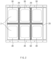
- FIG. 2 is a plan view of the battery pack from which a cover is removed according to an embodiment of the present invention.
- a battery pack 1 may include a plurality of battery modules 2.
- the battery modules 2 may be provided to enable electrical connection between the inside of the battery pack 1 and the outside of the battery pack 1.
- the battery pack 1 may include a case 10.
- the case 10 may define a portion of an outer appearance of battery pack 10.
- the case 10 may define lower and side portions of the battery pack 1.
- the battery pack 1 may include a cover 40.
- the cover 40 may cover an opened upper portion of the case 10.
- the cover 40 may be disposed to cover the upper portion of the case 10.
- the cover 40 may cover a plurality of compartments 30, which will be described later, at upper sides of partition walls 20, which will be described later.
- the case 10 and the cover 40 may define an inner space in which the battery modules 2 are accommodated.
- the case 10 may define side and lower portions of the battery pack 1, and the cover 40 may covers the opened upper portion of the case 10 and define an upper portion of the battery pack 1.
- a space surrounded by the case 10 and the cover 40 may form the inner space in which the battery modules 2 are accommodated.
- the battery pack 1 may include a plurality of compartments 30.
- the plurality of compartments 30 may be provided to accommodate the battery modules 2 in the inner space of the battery pack 1, but each of the battery modules 2 may be accommodated in an independent space.
- the battery pack 1 may include partition walls 20.
- the partition walls 20 may divide the inside of the case 10 into the plurality of compartments 30.
- the partition walls 20 may be disposed to pass through the inner space of the battery pack 1 so that the inside of the battery pack 1 (or the case 10) is partitioned (or divided) into the plurality of compartments 30.
- the battery modules 2 may be disposed (or accommodated) in the plurality of compartments 30.
- each of the battery modules 2 may be disposed in each of the plurality of compartments 30, but is not limited thereto.
- the battery pack 1 may include a flame retardant sheet 50.
- the flame retardant sheet 50 may be disposed between the partition walls 30 and the cover 40.
- the flame retardant sheet 50 may be disposed along an upper portion of each of the partition walls 30 between the partition walls 30 and the cover 40.
- the flame retardant sheet 50 may be coupled to each of the partition walls 30 and the cover 40 between the partition walls 30 and the cover 40.
- the flame retardant sheet 50 may be disposed along the upper portions of the partition walls 20 to suppress the propagation of the flame or gas between the plurality of compartments 30.
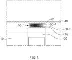
- FIG. 3 is a side view illustrating an arrangement of the frame retardant sheet 50 according to an embodiment of the present invention
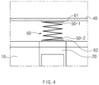
- FIG. 4 is a side view illustrating a deformation in shape of the frame retardant sheet 50 according to an embodiment of the present invention.
- the flame retardant sheet 50 may be attached to the partition walls 20 and the cover 40.
- a sheet upper portion 50-1 of the flame retardant sheet 50 may be attached to the cover 40.
- a sheet lower portion 50-2 of the flame retardant sheet 50 may be attached to the partition walls 20.
- the flame retardant sheet 50 may be installed in a folded state.
- the flame retardant sheet 50 may be installed in the folded state by being pressed by the partition walls 20 and the cover 40 between the partition walls 20 and the cover 40.
- the battery pack 1 may include an upper adhesive member 61 and a lower adhesive member 62.
- each of the upper adhesive member 61 and the lower adhesive member 62 may be a double-sided tape.
- the upper adhesive member 61 may attach the flame retardant sheet 50 (or the sheet upper portion 50-1) to the cover 40.
- the lower adhesive member 62 may attach the flame retardant sheet 50 (or the sheet lower portion 50-1) to the partition walls 20.
- the flame retardant sheet 50 may be deformed in shape.
- the flame retardant sheet 50 may be deformed in shape between the partition walls 20 and the cover 40 as the cover 40 moves.
- the flame retardant sheet 50 may be provided in a wrinkled or folded state between the partition walls 20 and the cover 40.
- the flame retardant sheet may be unfolded upward when the cover 40 moves upward due to an increase in the internal pressure of the plurality of compartments 30 by the plurality of battery modules 2.
- the flame retardant sheet 50 may prevent the flame or gas from being diffused through a passage provided by the structural deformation between the compartments 30.
- FIG. 5 is a side view of a battery pack according to another embodiment of the present invention
- FIG. 6 is a side view illustrating an arrangement of a frame retardant sheet according to another embodiment of the present invention
- FIG. 7 is a side view illustrating a deformation in shape of the frame retardant sheet according to another embodiment of the present invention.
- a battery pack 1a may include an extension part 21a.
- the extension part 21a may be a portion extending from each of partition walls 20a.
- the extension part 21a may extend upward from each of the partition walls 20a to pass through a cover 40a.
- the battery pack 1a may include a support member 22a.
- the support member 22a may be mounted on the extension part 21a.
- the support member 22a may be mounted to surround the extension part 21a.
- the support member 22a may be mounted on the extension part 21a and may be provided to support the cover 40a from an upper side.
- the cover 40a may be disposed between the support member 22a and a flame retardant sheet 50a.
- the support member 22a may be mounted on the extension part 21a to support the cover 40a from above so that movement of the cover 40a is suppressed to a predetermined degree. In this case, when the cover 40a moves upward, the support member 22a may suppress the movement of the cover 40a to the predetermined degree.
- the flame retardant sheet 50a may be inserted into the extension part 21a.
- the flame retardant sheet 50a may have holes penetrating in a vertical direction so as to be inserted into the extension part 21a.
- the flame retardant sheet 50a may be folded or unfolded as the cover 40a moves in the state of being inserted into the extension part 21a.
- the flame retardant sheet 50a may be unfolded or folded along an extension direction of the extension part 21a.
- a sheet upper portion 50-1a of the flame retardant sheet 50a may be attached to the cover 40a, and a sheet lower portion 50-2a may be attached to the partitions 20a.
- the flame retardant sheet 50a may be unfolded in a direction in which the extension part 21a extends (e.g., upward from the partitions 20a).
- a section in which the flame retardant sheet 50a is folded along the extension direction of the extension part 21a in a section in which the flame retardant sheet 50a is folded may be provided.
- the flame retardant sheet 50a may be unfolded or folded along the extension direction of the extension part 21a by the movement of the cover 40a in the state of being inserted into the extension part 21a. Even when the cover 40a is lifted due to the increase in internal pressure, the movement of the flame or gas between the plurality of compartments (e.g., reference numeral 30) may be suppressed due to blocking of the flame retardant sheet 50a.
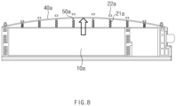
- FIG. 8 is a side view illustrating the battery pack 1a in which an increase in internal pressure occurs according to another embodiment of the present invention.
- the support member 22a may support (or press) the cover 40a from an upper side to suppress the movement of the cover 40a. If the increase in internal pressure due to the battery modules 2 becomes larger, the support member 22a may be detached from the extension part 21a. In this case as well, the flame retardant sheet 50a may be unfolded along the moving cover 40a. Since the flame retardant sheet 50a is unfolded or folded as the cover 40a moves, the flame retardant sheet 50a may block a moving path of the flame or gas between the compartments 30.
- the compartment structure When a lid (or cover) is expanded due to the internal pressure between the plurality of compartments (e.g., reference numeral 30) inside the battery packs 1 and 1a, the compartment structure may be released to generate a passage through which the flame or gas are propagated, thereby increasing in risk.
- the flame retardant sheets 50 and 50a may maintain the compartment structure even when the structure is deformed due to the increase in internal pressure. Therefore, the flame or gas may be prevented from being diffused through the passage provided by the structural deformation to improve stability of the battery packs 1 and 1a.
Landscapes
- Chemical & Material Sciences (AREA)
- Chemical Kinetics & Catalysis (AREA)
- Electrochemistry (AREA)
- General Chemical & Material Sciences (AREA)
- Battery Mounting, Suspending (AREA)
- Gas Exhaust Devices For Batteries (AREA)
Abstract
Description
- The present application claims the benefit of the priority of
Korean Patent Application No. 10-2022-0097612, filed on August 4, 2022 - The present invention relates to a battery pack including a flame retardant sheet.
- In response to environmental pollution and depletion of petroleum resources, research and development on power generation based on Eco-friendly energy sources are being conducted. Particularly, research on secondary batteries is being actively conducted, and research is being conducted on various aspects such as materials, structures, processes, and systems of the secondary batteries.
- In structural aspects, secondary batteries may be managed in units of modules and packs. Here, secondary battery cells are gathered to form a battery module, and battery modules are gathered to form a battery pack. In charging/discharging processes, a large amount of gas is generated by the secondary battery cells, or ignition may occur, and thus, safety management related thereto may be necessary.
- According to the related art, when a lid (or cover) is expanded due to an internal pressure by the gas in the battery pack, a compartment structure of the modules may be released to generate a passage through which flame or gas are propagated, thereby increasing in risk.
- An object of the present invention for solving the above problem is to provide a battery pack in which a compartment structure is maintained even if a cover moves as an internal pressure of the battery pack increases.
- A battery pack comprising a plurality of battery modules according to an embodiment of the present invention may include a case, partition walls configured to partition the inside of the case into a plurality of compartments, a plurality of battery modules disposed in the plurality of compartments, respectively, a cover configured to cover the plurality of compartments from an upper side of the partition walls, and a flame retardant sheet deformed between the partition walls and the cover as the cover moves.
- According to the preferred embodiment of the present invention, even if the structure is deformed due to the increase in internal pressure, the compartment structure may be maintained.
- According to the preferred embodiment of the present invention, the flame and gas may be prevented from being diffused through the passage provided by the structural deformation.
-
-
FIG. 1 is a perspective view of a battery pack according to an embodiment of the present invention. -
FIG. 2 is a plan view of the battery pack from which a cover is removed according to an embodiment of the present invention. -
FIG. 3 is a side view illustrating an arrangement of a frame retardant sheet according to an embodiment of the present invention. -
FIG. 4 is a side view illustrating a deformation in shape of the frame retardant sheet according to an embodiment of the present invention. -
FIG. 5 is a side view of a battery pack according to another embodiment of the present invention. -
FIG. 6 is a side view illustrating an arrangement of a frame retardant sheet according to another embodiment of the present invention. -
FIG. 7 is a side view illustrating a deformation in shape of the frame retardant sheet according to another embodiment of the present invention. -
FIG. 8 is a side view illustrating the battery pack in which an increase in internal pressure occurs according to another embodiment of the present invention. - Hereinafter, preferred embodiments of the present invention will be described in detail with reference to the accompanying drawings so that those of ordinary skill in the art may easily carry out the present invention. However, the present invention may be implemented in several different forms and is not limited or restricted by the following examples.
- In order to clearly explain the present invention, detailed descriptions of portions that are irrelevant to the description or related known technologies that may unnecessarily obscure the gist of the present invention have been omitted, and in the present specification, reference symbols are added to components in each drawing. In this case, the same or similar reference numerals are assigned to the same or similar elements throughout the specification.
- Also, terms or words used in this specification and claims should not be restrictively interpreted as ordinary meanings or dictionary-based meanings, but should be interpreted as meanings and concepts conforming to the scope of the present invention on the basis of the principle that an inventor may properly define the concept of a term to describe and explain his or her invention in the best ways.
-
FIG. 1 is a perspective view of a battery pack according to an embodiment of the present invention, andFIG. 2 is a plan view of the battery pack from which a cover is removed according to an embodiment of the present invention. - A
battery pack 1 may include a plurality ofbattery modules 2. Thebattery modules 2 may be provided to enable electrical connection between the inside of thebattery pack 1 and the outside of thebattery pack 1. - Referring to
FIG. 1 , thebattery pack 1 may include acase 10. Thecase 10 may define a portion of an outer appearance ofbattery pack 10. For example, thecase 10 may define lower and side portions of thebattery pack 1. - The
battery pack 1 may include acover 40. Thecover 40 may cover an opened upper portion of thecase 10. For example, thecover 40 may be disposed to cover the upper portion of thecase 10. In other words, thecover 40 may cover a plurality ofcompartments 30, which will be described later, at upper sides ofpartition walls 20, which will be described later. - The
case 10 and thecover 40 may define an inner space in which thebattery modules 2 are accommodated. For example, thecase 10 may define side and lower portions of thebattery pack 1, and thecover 40 may covers the opened upper portion of thecase 10 and define an upper portion of thebattery pack 1. A space surrounded by thecase 10 and thecover 40 may form the inner space in which thebattery modules 2 are accommodated. - The
battery pack 1 may include a plurality ofcompartments 30. For example, the plurality ofcompartments 30 may be provided to accommodate thebattery modules 2 in the inner space of thebattery pack 1, but each of thebattery modules 2 may be accommodated in an independent space. - The
battery pack 1 may includepartition walls 20. For example, thepartition walls 20 may divide the inside of thecase 10 into the plurality ofcompartments 30. In other words, thepartition walls 20 may be disposed to pass through the inner space of thebattery pack 1 so that the inside of the battery pack 1 (or the case 10) is partitioned (or divided) into the plurality ofcompartments 30. - The
battery modules 2 may be disposed (or accommodated) in the plurality ofcompartments 30. For example, each of thebattery modules 2 may be disposed in each of the plurality ofcompartments 30, but is not limited thereto. - The
battery pack 1 may include a flameretardant sheet 50. The flameretardant sheet 50 may be disposed between thepartition walls 30 and thecover 40. For example, the flameretardant sheet 50 may be disposed along an upper portion of each of thepartition walls 30 between thepartition walls 30 and thecover 40. In other words, the flameretardant sheet 50 may be coupled to each of thepartition walls 30 and thecover 40 between thepartition walls 30 and thecover 40. The flameretardant sheet 50 may be disposed along the upper portions of thepartition walls 20 to suppress the propagation of the flame or gas between the plurality ofcompartments 30. -
FIG. 3 is a side view illustrating an arrangement of the frameretardant sheet 50 according to an embodiment of the present invention, andFIG. 4 is a side view illustrating a deformation in shape of the frameretardant sheet 50 according to an embodiment of the present invention. - The flame
retardant sheet 50 may be attached to thepartition walls 20 and thecover 40. For example, a sheet upper portion 50-1 of the flameretardant sheet 50 may be attached to thecover 40. In addition, a sheet lower portion 50-2 of the flameretardant sheet 50 may be attached to thepartition walls 20. The flameretardant sheet 50 may be installed in a folded state. For example, the flameretardant sheet 50 may be installed in the folded state by being pressed by thepartition walls 20 and thecover 40 between thepartition walls 20 and thecover 40. - The
battery pack 1 may include an upperadhesive member 61 and a loweradhesive member 62. For example, each of theupper adhesive member 61 and the loweradhesive member 62 may be a double-sided tape. Theupper adhesive member 61 may attach the flame retardant sheet 50 (or the sheet upper portion 50-1) to thecover 40. The loweradhesive member 62 may attach the flame retardant sheet 50 (or the sheet lower portion 50-1) to thepartition walls 20. - The
flame retardant sheet 50 may be deformed in shape. For example, theflame retardant sheet 50 may be deformed in shape between thepartition walls 20 and thecover 40 as thecover 40 moves. Theflame retardant sheet 50 may be provided in a wrinkled or folded state between thepartition walls 20 and thecover 40. For a specific example, the flame retardant sheet may be unfolded upward when thecover 40 moves upward due to an increase in the internal pressure of the plurality ofcompartments 30 by the plurality ofbattery modules 2. As theflame retardant sheet 50 is unfolded, even when thecover 40 moves upward, the movement of the flame or gas between the plurality ofcompartments 30 may be suppressed. In other words, theflame retardant sheet 50 may prevent the flame or gas from being diffused through a passage provided by the structural deformation between thecompartments 30. -
FIG. 5 is a side view of a battery pack according to another embodiment of the present invention,FIG. 6 is a side view illustrating an arrangement of a frame retardant sheet according to another embodiment of the present invention, andFIG. 7 is a side view illustrating a deformation in shape of the frame retardant sheet according to another embodiment of the present invention. - A battery pack 1a may include an
extension part 21a. For example, theextension part 21a may be a portion extending from each ofpartition walls 20a. Specifically, theextension part 21a may extend upward from each of thepartition walls 20a to pass through acover 40a. - The battery pack 1a may include a
support member 22a. For example, thesupport member 22a may be mounted on theextension part 21a. Thesupport member 22a may be mounted to surround theextension part 21a. - The
support member 22a may be mounted on theextension part 21a and may be provided to support thecover 40a from an upper side. For example, thecover 40a may be disposed between thesupport member 22a and aflame retardant sheet 50a. Thesupport member 22a may be mounted on theextension part 21a to support thecover 40a from above so that movement of thecover 40a is suppressed to a predetermined degree. In this case, when thecover 40a moves upward, thesupport member 22a may suppress the movement of thecover 40a to the predetermined degree. - The
flame retardant sheet 50a may be inserted into theextension part 21a. For example, theflame retardant sheet 50a may have holes penetrating in a vertical direction so as to be inserted into theextension part 21a. In other words, theflame retardant sheet 50a may be folded or unfolded as thecover 40a moves in the state of being inserted into theextension part 21a. - The
flame retardant sheet 50a may be unfolded or folded along an extension direction of theextension part 21a. For example, a sheet upper portion 50-1a of theflame retardant sheet 50a may be attached to thecover 40a, and a sheet lower portion 50-2a may be attached to thepartitions 20a. When thecover 40a moves upward due to an increase in internal pressure caused by the plurality ofbattery modules 2, theflame retardant sheet 50a may be unfolded in a direction in which theextension part 21a extends (e.g., upward from thepartitions 20a). Alternatively, a section in which theflame retardant sheet 50a is folded along the extension direction of theextension part 21a in a section in which theflame retardant sheet 50a is folded may be provided. Theflame retardant sheet 50a may be unfolded or folded along the extension direction of theextension part 21a by the movement of thecover 40a in the state of being inserted into theextension part 21a. Even when thecover 40a is lifted due to the increase in internal pressure, the movement of the flame or gas between the plurality of compartments (e.g., reference numeral 30) may be suppressed due to blocking of theflame retardant sheet 50a. -
FIG. 8 is a side view illustrating the battery pack 1a in which an increase in internal pressure occurs according to another embodiment of the present invention. - When the
cover 40a is lifted due to an increase in internal pressure caused by thebattery modules 2, thesupport member 22a may support (or press) thecover 40a from an upper side to suppress the movement of thecover 40a. If the increase in internal pressure due to thebattery modules 2 becomes larger, thesupport member 22a may be detached from theextension part 21a. In this case as well, theflame retardant sheet 50a may be unfolded along the movingcover 40a. Since theflame retardant sheet 50a is unfolded or folded as thecover 40a moves, theflame retardant sheet 50a may block a moving path of the flame or gas between thecompartments 30. - When a lid (or cover) is expanded due to the internal pressure between the plurality of compartments (e.g., reference numeral 30) inside the battery packs 1 and 1a, the compartment structure may be released to generate a passage through which the flame or gas are propagated, thereby increasing in risk. As described above, the
flame retardant sheets - While the embodiments of the present invention have been described with reference to the specific embodiments, it will be apparent to those skilled in the art that various changes and modifications may be made without departing from the spirit and scope of the invention as defined in the following claims.
-
- 1, 1a: Battery pack
- 2: Battery modules
- 10, 10a: Case
- 20, 20a: Partition walls
- 21, 21a: Extension part
- 22, 22a: Support member
- 30, 30a: Plurality of compartments
- 40,40a: Cover
- 50,50a: Flame retardant sheet
- 50-1, 50-1a: Sheet upper portion
- 50-2, 50-2a: Sheet lower portion
- 61: Upper adhesive member
- 62: Lower adhesive member
Claims (10)
- A battery pack comprising a plurality of battery modules, the battery pack comprising:a case;partition walls configured to partition the inside of the case into a plurality of compartments;a plurality of battery modules disposed in the plurality of compartments, respectively;a cover configured to cover the plurality of compartments from an upper side of the partition walls; anda flame retardant sheet deformed between the partition walls and the cover as the cover moves.
- The battery pack of claim 1, wherein the flame retardant sheet is installed in a folded state between the partition walls and the cover.
- The battery pack of claim 1, wherein the flame retardant sheet is unfolded upward when the cover moves upward due to an increase in internal pressure by the plurality of battery modules.
- The battery pack of claim 1, wherein the flame retardant sheet comprises:a sheet upper portion attached to the cover; anda sheet lower portion attached to the partition walls.
- The battery pack of claim 1, wherein the flame retardant sheet is disposed along upper portions of the partition walls to suppress propagation of flame or a gas between the plurality of compartments.
- The battery pack of claim 1, further comprising:an upper adhesive member configured to attach the flame retardant sheet to the cover; anda lower adhesive member configured to attach the flame retardant sheet to the partition walls.
- The battery pack of claim 1, wherein the flame retardant sheet is configured to suppress movement of flame or a gas between the plurality of compartments.
- The battery pack of claim 1, further comprising:extension parts extending upward to pass from the partition walls to the cover; andsupport members extending from the extension parts to support the cover at an upper side.
- The battery pack of claim 8, wherein the flame retardant sheet has a hole penetrated in a vertical direction so as to be inserted into the extension parts.
- The battery pack of claim 9, wherein the flame retardant sheet comprises:an upper portion attached to the cover; anda lower portion attached to the partition walls,wherein the flame retardant sheet is unfolded along the extension direction of the extension parts when the cover moves upward due to an increase in internal pressure by the plurality of battery modules.
Applications Claiming Priority (2)
| Application Number | Priority Date | Filing Date | Title |
|---|---|---|---|
| KR1020220097612A KR20240019649A (en) | 2022-08-04 | 2022-08-04 | Battery pack |
| PCT/KR2023/011435 WO2024029968A1 (en) | 2022-08-04 | 2023-08-03 | Battery pack |
Publications (2)
| Publication Number | Publication Date |
|---|---|
| EP4550544A1 true EP4550544A1 (en) | 2025-05-07 |
| EP4550544A4 EP4550544A4 (en) | 2025-06-25 |
Family
ID=89849621
Family Applications (1)
| Application Number | Title | Priority Date | Filing Date |
|---|---|---|---|
| EP23850468.2A Pending EP4550544A4 (en) | 2022-08-04 | 2023-08-03 | Battery pack |
Country Status (5)
| Country | Link |
|---|---|
| EP (1) | EP4550544A4 (en) |
| JP (1) | JP2025524710A (en) |
| KR (1) | KR20240019649A (en) |
| CN (1) | CN119585929A (en) |
| WO (1) | WO2024029968A1 (en) |
Families Citing this family (2)
| Publication number | Priority date | Publication date | Assignee | Title |
|---|---|---|---|---|
| KR20250139705A (en) * | 2024-03-15 | 2025-09-23 | 주식회사 엘지에너지솔루션 | Battery system and vehicle comprising the same |
| KR20250161220A (en) * | 2024-05-08 | 2025-11-17 | 주식회사 엘지에너지솔루션 | Battery pack |
Family Cites Families (11)
| Publication number | Priority date | Publication date | Assignee | Title |
|---|---|---|---|---|
| DE4232961A1 (en) * | 1992-10-01 | 1994-04-07 | Vb Autobatterie Gmbh | Multi-cell lead accumulator |
| US20050170238A1 (en) * | 2004-02-04 | 2005-08-04 | Abu-Isa Ismat A. | Fire shielding battery case |
| KR102061745B1 (en) * | 2016-04-25 | 2020-01-02 | 주식회사 엘지화학 | Battery pack and vehicle comprising the battery pack |
| KR102075101B1 (en) * | 2016-08-10 | 2020-03-02 | 주식회사 엘지화학 | Battery pack improved in cooling structure |
| JP7010671B2 (en) * | 2017-11-15 | 2022-01-26 | スカッドエレクトロニクスジャパン株式会社 | Lithium ion battery module |
| JP7351854B2 (en) * | 2018-12-21 | 2023-09-27 | 阿波製紙株式会社 | Power supply equipment and insulation sheets for power supply equipment |
| KR102748983B1 (en) * | 2019-07-03 | 2024-12-30 | 주식회사 엘지에너지솔루션 | Battery Module Including Flame Retardant Plate, Battery Rack and Power Storage Device Including the Same |
| KR102924941B1 (en) * | 2020-08-13 | 2026-02-09 | 에스케이온 주식회사 | Battery module |
| KR102953580B1 (en) * | 2020-08-26 | 2026-04-15 | 주식회사 엘지에너지솔루션 | Large battery module and a bettery pack including the same |
| JP7636439B2 (en) * | 2020-08-31 | 2025-02-26 | エルジー エナジー ソリューション リミテッド | Battery module and battery pack including same |
| KR102572856B1 (en) | 2020-12-30 | 2023-09-01 | 세메스 주식회사 | Method and apparatus for treating substrate |
-
2022
- 2022-08-04 KR KR1020220097612A patent/KR20240019649A/en active Pending
-
2023
- 2023-08-03 EP EP23850468.2A patent/EP4550544A4/en active Pending
- 2023-08-03 JP JP2025503153A patent/JP2025524710A/en active Pending
- 2023-08-03 CN CN202380055412.2A patent/CN119585929A/en active Pending
- 2023-08-03 WO PCT/KR2023/011435 patent/WO2024029968A1/en not_active Ceased
Also Published As
| Publication number | Publication date |
|---|---|
| EP4550544A4 (en) | 2025-06-25 |
| KR20240019649A (en) | 2024-02-14 |
| WO2024029968A1 (en) | 2024-02-08 |
| CN119585929A (en) | 2025-03-07 |
| JP2025524710A (en) | 2025-07-30 |
Similar Documents
| Publication | Publication Date | Title |
|---|---|---|
| JP6801107B2 (en) | Drawer type battery pack | |
| CN103493241B (en) | Battery container, sub-battery container used in battery container, and battery pack using them | |
| CN119585929A (en) | Battery pack | |
| US12218332B2 (en) | Battery pack comprising heat diffusion preventing member | |
| JP2014179298A (en) | Power supply module | |
| KR101833567B1 (en) | Tray for charge and discharge regulator having a fixed function of battery cell | |
| KR20230167969A (en) | Battery pack | |
| EP4468466A1 (en) | Battery module with reinforced safety | |
| KR102834823B1 (en) | Battery Pack | |
| EP4708518A1 (en) | Fastening mechanism, and battery pack including fastening mechanism | |
| US20260128459A1 (en) | Battery pack and vehicle including the same | |
| EP4398390A1 (en) | Frame including guideline, and battery module including frame | |
| EP4708519A1 (en) | Fastening device and battery pack comprising fastening device | |
| US20260135250A1 (en) | Battery pack and vehicle including the same | |
| US20250141036A1 (en) | Battery housing | |
| EP4068485A1 (en) | Battery module | |
| EP4546526A1 (en) | Battery pack | |
| EP4498493A1 (en) | Battery module | |
| EP4415151B1 (en) | End plate assembly and battery module including the same | |
| KR20260069211A (en) | Battery pack and vehicle including the same | |
| KR20230157648A (en) | Lighrweight and Rigid Battery Module Housing and Battery Pack Comprising the Same | |
| EP4401219A1 (en) | Battery module for preventing battery rupture | |
| KR20260066371A (en) | Battery pack and vehicle including the same | |
| KR20240159412A (en) | Battery pack and vehicle comprising the battery pack | |
| KR20260073146A (en) | Battery pack and vehicle including the same |
Legal Events
| Date | Code | Title | Description |
|---|---|---|---|
| STAA | Information on the status of an ep patent application or granted ep patent |
Free format text: STATUS: THE INTERNATIONAL PUBLICATION HAS BEEN MADE |
|
| PUAI | Public reference made under article 153(3) epc to a published international application that has entered the european phase |
Free format text: ORIGINAL CODE: 0009012 |
|
| STAA | Information on the status of an ep patent application or granted ep patent |
Free format text: STATUS: REQUEST FOR EXAMINATION WAS MADE |
|
| 17P | Request for examination filed |
Effective date: 20250131 |
|
| AK | Designated contracting states |
Kind code of ref document: A1 Designated state(s): AL AT BE BG CH CY CZ DE DK EE ES FI FR GB GR HR HU IE IS IT LI LT LU LV MC ME MK MT NL NO PL PT RO RS SE SI SK SM TR |
|
| A4 | Supplementary search report drawn up and despatched |
Effective date: 20250528 |
|
| RIC1 | Information provided on ipc code assigned before grant |
Ipc: H01M 50/383 20210101ALI20250522BHEP Ipc: H01M 50/242 20210101ALI20250522BHEP Ipc: H01M 50/238 20210101ALI20250522BHEP Ipc: H01M 50/218 20210101ALI20250522BHEP Ipc: H01M 50/207 20210101ALI20250522BHEP Ipc: H01M 50/211 20210101ALI20250522BHEP Ipc: H01M 50/24 20210101AFI20250522BHEP |
|
| DAV | Request for validation of the european patent (deleted) | ||
| DAX | Request for extension of the european patent (deleted) |