EP4550543A1 - Battery module - Google Patents
Battery module Download PDFInfo
- Publication number
- EP4550543A1 EP4550543A1 EP23850262.9A EP23850262A EP4550543A1 EP 4550543 A1 EP4550543 A1 EP 4550543A1 EP 23850262 A EP23850262 A EP 23850262A EP 4550543 A1 EP4550543 A1 EP 4550543A1
- Authority
- EP
- European Patent Office
- Prior art keywords
- battery module
- connector
- disposed
- circuit board
- protective plate
- Prior art date
- Legal status (The legal status is an assumption and is not a legal conclusion. Google has not performed a legal analysis and makes no representation as to the accuracy of the status listed.)
- Pending
Links
Images




Classifications
-
- H—ELECTRICITY
- H01—ELECTRIC ELEMENTS
- H01M—PROCESSES OR MEANS, e.g. BATTERIES, FOR THE DIRECT CONVERSION OF CHEMICAL ENERGY INTO ELECTRICAL ENERGY
- H01M50/00—Constructional details or processes of manufacture of the non-active parts of electrochemical cells other than fuel cells, e.g. hybrid cells
- H01M50/20—Mountings; Secondary casings or frames; Racks, modules or packs; Suspension devices; Shock absorbers; Transport or carrying devices; Holders
- H01M50/204—Racks, modules or packs for multiple batteries or multiple cells
- H01M50/207—Racks, modules or packs for multiple batteries or multiple cells characterised by their shape
- H01M50/211—Racks, modules or packs for multiple batteries or multiple cells characterised by their shape adapted for pouch cells
-
- H—ELECTRICITY
- H01—ELECTRIC ELEMENTS
- H01M—PROCESSES OR MEANS, e.g. BATTERIES, FOR THE DIRECT CONVERSION OF CHEMICAL ENERGY INTO ELECTRICAL ENERGY
- H01M10/00—Secondary cells; Manufacture thereof
- H01M10/42—Methods or arrangements for servicing or maintenance of secondary cells or secondary half-cells
- H01M10/425—Structural combination with electronic components, e.g. electronic circuits integrated to the outside of the casing
-
- H—ELECTRICITY
- H01—ELECTRIC ELEMENTS
- H01M—PROCESSES OR MEANS, e.g. BATTERIES, FOR THE DIRECT CONVERSION OF CHEMICAL ENERGY INTO ELECTRICAL ENERGY
- H01M50/00—Constructional details or processes of manufacture of the non-active parts of electrochemical cells other than fuel cells, e.g. hybrid cells
- H01M50/20—Mountings; Secondary casings or frames; Racks, modules or packs; Suspension devices; Shock absorbers; Transport or carrying devices; Holders
- H01M50/284—Mountings; Secondary casings or frames; Racks, modules or packs; Suspension devices; Shock absorbers; Transport or carrying devices; Holders with incorporated circuit boards, e.g. printed circuit boards [PCB]
-
- H—ELECTRICITY
- H01—ELECTRIC ELEMENTS
- H01M—PROCESSES OR MEANS, e.g. BATTERIES, FOR THE DIRECT CONVERSION OF CHEMICAL ENERGY INTO ELECTRICAL ENERGY
- H01M50/00—Constructional details or processes of manufacture of the non-active parts of electrochemical cells other than fuel cells, e.g. hybrid cells
- H01M50/50—Current conducting connections for cells or batteries
- H01M50/502—Interconnectors for connecting terminals of adjacent batteries; Interconnectors for connecting cells outside a battery casing
- H01M50/503—Interconnectors for connecting terminals of adjacent batteries; Interconnectors for connecting cells outside a battery casing characterised by the shape of the interconnectors
-
- H—ELECTRICITY
- H01—ELECTRIC ELEMENTS
- H01M—PROCESSES OR MEANS, e.g. BATTERIES, FOR THE DIRECT CONVERSION OF CHEMICAL ENERGY INTO ELECTRICAL ENERGY
- H01M50/00—Constructional details or processes of manufacture of the non-active parts of electrochemical cells other than fuel cells, e.g. hybrid cells
- H01M50/50—Current conducting connections for cells or batteries
- H01M50/502—Interconnectors for connecting terminals of adjacent batteries; Interconnectors for connecting cells outside a battery casing
- H01M50/505—Interconnectors for connecting terminals of adjacent batteries; Interconnectors for connecting cells outside a battery casing comprising a single busbar
-
- H—ELECTRICITY
- H01—ELECTRIC ELEMENTS
- H01M—PROCESSES OR MEANS, e.g. BATTERIES, FOR THE DIRECT CONVERSION OF CHEMICAL ENERGY INTO ELECTRICAL ENERGY
- H01M50/00—Constructional details or processes of manufacture of the non-active parts of electrochemical cells other than fuel cells, e.g. hybrid cells
- H01M50/50—Current conducting connections for cells or batteries
- H01M50/502—Interconnectors for connecting terminals of adjacent batteries; Interconnectors for connecting cells outside a battery casing
- H01M50/519—Interconnectors for connecting terminals of adjacent batteries; Interconnectors for connecting cells outside a battery casing comprising printed circuit boards [PCB]
-
- Y—GENERAL TAGGING OF NEW TECHNOLOGICAL DEVELOPMENTS; GENERAL TAGGING OF CROSS-SECTIONAL TECHNOLOGIES SPANNING OVER SEVERAL SECTIONS OF THE IPC; TECHNICAL SUBJECTS COVERED BY FORMER USPC CROSS-REFERENCE ART COLLECTIONS [XRACs] AND DIGESTS
- Y02—TECHNOLOGIES OR APPLICATIONS FOR MITIGATION OR ADAPTATION AGAINST CLIMATE CHANGE
- Y02E—REDUCTION OF GREENHOUSE GAS [GHG] EMISSIONS, RELATED TO ENERGY GENERATION, TRANSMISSION OR DISTRIBUTION
- Y02E60/00—Enabling technologies; Technologies with a potential or indirect contribution to GHG emissions mitigation
- Y02E60/10—Energy storage using batteries
Definitions
- the present invention relates to a battery module, and more particularly, to a secondary battery module including a plurality of cells.
- Batteries storing electrical energy may be generally classified into primary batteries and a secondary batteries.
- a primary battery is a disposable consumable battery.
- a secondary battery is a chargeable battery that is manufactured by using a material in which oxidation and reduction processes between current and the material are capable of being repeated. That is, when the reduction reaction to the material is performed by the current, power is charged. When the oxidation reaction to the material is performed by the current, power is discharged. Such charging-discharging are repeatedly performed to generate electricity.
- the battery module according to the related art has a problem in that a connector of the battery module is destroyed due to the flame generated in the battery module. In addition, there is a problem that thermal propagation is accelerated to other adjacent battery modules through a space generated due to the loss of the connector.
- the present invention has been invented to solve the above problem, and an object of the present invention is to provide a battery module capable of preventing or delaying a loss of a connector due to flame generated therein to delay thermal propagation to the outside.
- a battery module may include cell assemblies, each of which includes a plurality of cells, a busbar frame on which a busbar configured to electrically connect the cell assemblies to each other is disposed, an endplate disposed on each of both ends of the cell assembly to cover the busbar frame, a circuit board that is in contact with the busbar so as to be electrically connected to the cell assembly, a connector configured to electrically connect the circuit board to the outside, and a protective plate disposed between the circuit board and the connector to protect the connector from being deformed due to heat.
- the connector may include a terminal part including a plurality of terminals that are in contact with the circuit board so as to perform electrical connection, and a housing configured to cover a side surface of the terminal part.
- the battery module may further include an insulating case comprising an insulating material and disposed between the endplate and the busbar frame to cover a portion of the housing.
- the protective plate may include a potting part disposed at a position corresponding to a portion at which the terminal part is disposed, and the terminal may extend to pass through the potting part.
- the potting part may be formed through silicon potting.
- the protective plate may further include a metal part configured to cover one surface of the connector, which faces the potting part, together with the potting part.
- the protective plate may further include a bent part disposed on each of both ends of the metal part and having a bent shape.
- the end plate may include a corresponding part disposed at a position corresponding to the bent part and bent in a shape corresponding to the bent part.
- the circuit board may include a reinforcement plate that is in contact with the terminal and disposed on one surface facing the protective plate.
- the connector may further include a fixing part connected to both ends of the housing and fixed to the busbar frame.
- the fixing part may have a coupling hole that passes from one surface facing the busbar frame to the other surface, wherein the fixing part may be fixed to the busbar frame while a connection member is inserted into the coupling hole.
- the circuit board may include a printed circuit board (PCB).
- PCB printed circuit board
- the circuit board may include a flexible printed circuit board (FPCB).
- FPCB flexible printed circuit board
- the bent part may be disposed to be caught on the corresponding part so as to be prevented from moving toward the connector.
- the battery module according to the present invention may include the cell assemblies, each of which includes the plurality of cells, the busbar frame on which the busbar electrically connecting the cell assemblies to each other is disposed, the endplate disposed on each of both the ends of the cell assembly to cover the busbar frame, the circuit board that is in contact with the busbar so as to be electrically connected to the cell assembly, the connector electrically connecting the circuit board to the outside, and the protective plate disposed between the circuit board and the connector to protect the connector from being deformed due to the heat.
- the connector may be prevented and delayed from being destroyed due to the flame generated in the battery module.
- the connector of the battery module may be prevented from protruding out of the battery module.
- the thermal propagation from the battery module to the adjacent battery module may be delayed.
- the present invention provides a battery module as Embodiment 1.
- FIG. 1 is a schematic exploded perspective view of a battery module 10 according to Embodiment 1 of the present invention
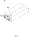
- FIG. 2 is a schematic perspective view illustrating the battery module 10 according to Embodiment 1 of the present invention.
- the battery module 10 may include cell assemblies 100, a busbar frame 200, an endplate 300, a circuit board 400, and a connector 500, and a protective plate 600.
- the predetermined number of cells may be stacked to generate electrical energy.
- the cells constituting the cell assembly 100 may mean one secondary battery.
- the cell may be a pouch cell.
- the plurality of cells may be stacked side by side in parallel to each other.
- the busbar frame 200 may be disposed on one end or both ends of the cell assembly 100 according to Embodiment 1 of the present invention.
- the busbar may be connected to an electrode lead of the cell assembly 100 to electrically connect the cell assemblies 100 to each other, and the busbar may be disposed on the busbar frame 200.
- the endplate 300 of the battery module 10 according to Embodiment 1 of the present invention may be disposed at each of both the ends of the cell assembly 100. Specifically, the endplates 300 may be placed at opposite sides of the cell assembly 100 with the busbar frame 200 therebetween.
- the battery module 10 according to Embodiment 1 of the present invention may further include a frame 800.
- the frame 800 may be disposed to surround the cell assembly 100.
- the frame 800 may be coupled to the endplate to protect the cell assembly 100.
- the endplate 300 may be coupled to the frame 800 to protect the busbar disposed therein.
- a shape of the frame 800 described in the present invention is only an example, and the frame 800 may have various shapes capable of protecting the cell assembly 100.
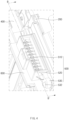
- FIG. 3 is an schematic enlarged view illustrating a portion A of FIG. 2
- FIG. 4 is a schematic perspective view illustrating a state before the endplate 300 is assembled in FIG. 3
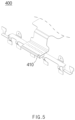
- FIG. 5 is a schematic perspective view illustrating the circuit board 400 of the battery module 10 according to Embodiment 1 of the present invention
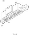
- FIG. 6 is a schematic perspective view illustrating the connector 500 of the battery module 10 according to Embodiment 1 of the present invention.
- the circuit board 400 of the battery module 10 according to Embodiment 1 of the present invention may be in contact with the busbar.
- the circuit board 400 may be in contact with the busbar connected to the electrode lead of the cell assembly 100 so as to be electrically connected to the cell assembly 100.
- the circuit board 400 may have a shape extending in a longitudinal direction of the cell assembly 100 and may include a central portion disposed at an upper portion of the cell assembly 100 and ends disposed on both distal ends of the central portion.
- the present invention deals in detail with an arrangement relationship between the ends of the circuit board 400 and other components.
- the circuit board 400 according to Embodiment 1 of the present invention may be a printed circuit board (PCB).
- the circuit board 400 may be a flexible printed circuit board (FPCB).
- FPCB flexible printed circuit board
- the circuit board 400 according to Embodiment 1 of the present invention may have excellent ductility, be easy to be molded into a desired shape, and have a thin plate shape, which is advantageous in terms of space utilization.
- the circuit board 400 of the battery module 10 according to Embodiment 1 of the present invention may include a reinforcement plate 410.
- the reinforcement plate 410 may be disposed on one surface facing the protective plate 600, which will be described later, at the end of the circuit board 400.
- the reinforcement plate 410 may be disposed to be in contact with the protective plate 600 and may be in contact with terminals 511 provided in the terminal part 510 of the connector 500, which will be described later.
- the portion of the reinforcement plate 410, which is in contact with the terminals 511, may have to be electrically connected to the terminals 511 and thus may be made of a conductor.
- the reinforcement plate 410 may have a thin plate shape and specifically may have a plate shape with a substantially rectangular cross-section.
- the structural stability may be supplemented by disposing the reinforcement plate 410 so as to be in contact with the protective plate 600.
- the connector 500 of the battery module 10 according to Embodiment 1 of the present invention may electrically connect the circuit board 400 to the outside.
- the connector 500 may be disposed to be exposed to the outside through an opened space defined in the endplate 300.
- the connector 500 may be disposed to be in contact with the circuit board 400. The electrical energy generated by the battery module 10 may be transmitted to the outside through the connector 500.
- the terminal part 510 of the connector 500 may include a plurality of terminals 511 that is in direct contact with the circuit board 400 for the electrical connection.
- Each of the terminals 511 may have a shape extending in a width direction of the connector 500.
- each terminal 511 may have a substantially bar shape.
- the housing 520 may be provided to cover a side surface of the terminal part 510.
- the housing 520 may have a shape of which both surfaces facing each other in an extension direction of the terminal part 510 are opened, and other side surfaces are covered.
- the terminal 511 of the terminal part 510 may be connected to the outside and the circuit board 400 through both the opened surfaces.
- the connector 500 of the battery module 10 according to Embodiment 1 of the present invention may further include a fixing part 530.
- the fixing part 530 may be connected to both ends of the housing 520 of the connector 500.
- the fixing part 530 may be provided in a shape extending in a direction away from the housing 520. More specifically, the fixing part 530 may be disposed adjacent to the busbar frame 200 at both the ends of the housing 520 for the connection to the busbar frame 200.
- the connector 500 may be fixed, and the structural stability may be improved.
- a coupling hole 531 may be defined in the fixing part 530 of the connector 500 according to Embodiment 1 of the present invention.
- the coupling hole 531 may be provided in a shape that passes from one side of the fixing part 530 facing the busbar frame 200 to the other side.
- the coupling hole 531 may be defined to have a substantially circular cross-section to facilitate insertion of the connection member 532.
- connection member 532 may be inserted into the coupling hole 531 defined in the fixing part 530, and the connection member 532 passing through the coupling hole 531 may be coupled to the busbar frame 200. As a result, the connector 500 may be fixed to the busbar frame 200.
- connection member 532 may be a bolt.
- a screw thread may be disposed on an inner surface of the coupling hole 531 so that the connection member 532 that is the bolt is inserted to be coupled.
- the coupling hole 531 may be defined in the fixing part 530 of the connector 500, and thus, the connector 500 may be efficiently fixed to the busbar frame 200.
- FIG. 7 is a schematic perspective view illustrating a state when a cross-section taken along line B-B' of FIG. 4 is viewed from the front.
- the battery module 10 according to Embodiment 1 of the present invention may include the protective plate 600.
- the protective plate 600 may be disposed between the circuit board 400 and the connector 500 and may prevent the connector 500 from being deformed due to heat. Specifically, the protective plate 600 may prevent the terminal part 510 of the connector 500 from being deformed or destroyed due to the heat or flame generated from the cell assembly 100 disposed inside the battery module 10.
- the protective plate 600 according to Embodiment 1 of the present invention may include a potting part 610.
- the potting part 610 may be disposed at a position corresponding to the portion at which the terminal part 510 of the connector 500 is disposed. Specifically, the terminal 511 of the terminal part 510 may be disposed to extend through the potting part 610. Here, the terminal 511 extending through the potting part 610 may be in contact with the reinforcement plate 410 of the circuit board 400.
- the potting part 610 may have a plate shape with a substantially rectangular cross-section and may be provided to have a cross-sectional area greater than or equal to the cross-sectional area of the terminal part 510. Thus, when the potting part 610 is viewed from an opposite side of the terminal part 510, the terminal part 510 may be covered by the potting part 610.
- the potting part 610 according to Embodiment 1 of the present invention may be formed through silicon potting.
- the silicon potting may refer to a process of applying silicon in liquid form to cover electrical components or fill a gap.
- the terminal 511 may be fixed, and an empty space may be efficiently filled at the same time, and thus, efficiency in manufacturing process may be improved.
- Silicon used to form the potting part 610 of the protective plate 600 according to Embodiment 1 of the present invention may be highly heat-resistant silicon.
- the potting part 610 may be advantageous in withstanding a high temperature, and thus, the terminal part 510 may be prevented or delayed from being deformed or destroyed.
- the protective plate 600 of the battery module 10 according to Embodiment 1 of the present invention may further include a metal part 620.
- the metal part 620 may cover one surface of the connector 500 together with the potting part 610. Specifically, the metal part 620 may cover one surface of the connector 500 facing the potting part 610 together with the potting part 610. Thus, when the metal part 620 is viewed from an opposite side of the connector 500, the connector 500 may be covered by the metal part 620.
- the metal part 620 may be made of a metal. Specifically, the metal part 620 may be made of a metal with excellent heat resistance. Thus, the metal part 620 may withstand the high temperatures, and thus, the connector 500 may be prevented from being deformed or delayed due to the high temperature.
- the metal part 620 may be provided to have a substantially rectangular cross-section and may be provided to have a cross-sectional area greater than or equal to the cross-sectional area of the connector 500 so as to cover the connector 500.
- the protective plate 600 includes the metal part 620, the connector 500 may be protected from flame generated inside the battery module 10.
- the battery module 10 according to Embodiment 1 of the present invention may further include an insulating case 700.
- the insulating case 700 may be disposed to cover a portion of the connector 500. Specifically, the insulating case 700 may be disposed between the endplate 300 and the busbar frame 200 to cover a portion of the housing 520.
- the connector 500 and the busbar may be insulated from other components. Thus, it is possible to prevent unnecessary short circuits, etc. from occurring, and thus, the stability of the battery module 10 may be improved.
- the heat and flame may be generated in the cell assembly 100 provided in the battery module 10, and the heat and flame may be spread from the inside of the battery module 10 to the outside. Since the battery module 10 according to Embodiment 1 of the present invention includes the protective plate 600, even if the insulating case 700, etc. is melted by the heat, the protective plate 600 may block the flame, etc. that is directed to the connector 500. Thus, it is possible to prevent the connector 500 from protruding to the outside. In addition, the terminal part 510 of the connector 500 may be protected by the potting part 610 of the protective plate 600. Thus, the battery module 10 according to Embodiment 1 of the present invention may efficiently withstand the high temperatures to increase in time taken to respond to the flam, etc.
- the present invention provides a battery module including a different type of protective plate 600' as Embodiment 2.
- FIG. 8 is a schematic perspective view illustrating a state before an endplate 300 is assembled in a battery module according to Embodiment 2 of the present invention
- FIG. 9 is a schematic perspective view illustrating the protective plate 600' of the battery module according to Embodiment 2 of the present invention
- FIG. 10 is a schematic perspective view illustrating a state in which a connector 500 and the protective plate 600' of the battery module are coupled to each other according to Embodiment 2 of the present invention.
- the protective plate 600' of the battery module according to Embodiment 2 of the present invention may further include a bent part 630.
- the bent part 630 may be disposed at each of both ends of a metal part 620. Specifically, the bent part 630 may be disposed to extend from both ends of the metal part 620 in a direction away from a potting part 610.
- the bent part 630 may have a bent shape. Referring to FIG. 9 , the bent part 630 may include a portion extending in a direction perpendicular to an extension direction of the metal part 620 and a portion provided by being bent in a direction parallel to the extending direction of the metal part 620.
- the protective plate 600' according to Embodiment 2 of the present invention may have the same configuration as the protective plate 600 according to Embodiment 1 of the present invention except for the bent part 630.
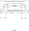
- FIG. 11 is a schematic perspective view illustrating a state when a cross-section taken along line C-C' of FIG. 8 is viewed from the front.
- the protective plate 600' according to Embodiment 2 of the present invention includes the bent part 630 and thus may cover an area greater than that of the protective plate 600 according to Embodiment 1 of the present invention.
- an endplate 300 of the battery module according to Embodiment 2 of the present invention may be bent into a shape corresponding to the bent part 630.
- a portion of the endplate 300 disposed at a position corresponding to the bent part 630 may be bent into a shape corresponding to the bent part 630.
- the portion of the endplate 300, which is bent into the shape corresponding to the bent part 630 is referred to as a corresponding part 310 (see FIG. 3 ).
- the corresponding part 310 of the endplate 300 and the bent part 630 of the protective plate 600' may be bent into corresponding shapes with the insulating case 700 therebetween. Therefore, even if the insulating case 700 is melted by flame generated inside the battery module, the bent part 630 of the protective plate 600' may be caught on the corresponding part 310 of the endplate 300 to efficiently cover the connector 500 from the flame.
- the corresponding part 310 of the endplate 300 may be a coupling member for connection to a frame 800 or a busbar frame 200.
- the frame 800 may refer to a case surrounding a cell assembly 100 (see FIG. 1 ).
- the endplate 300 may be coupled to the frame 800 surrounding an outer surface of the cell assembly 100 to protect the cell assembly 100. That is, the endplate 300 may protect the cell assembly 100 from the outside together with the frame 800.
- the busbar frame 200 since the busbar frame 200 is disposed between the endplate 300 and the cell assembly 100, the endplate 300 may protect the busbar frame 200 from the outside.
- the coupling member of the endplate 300 may be assembled with additional components such as a bolt and a nut to couple the endplate 300 to the frame 800 or the busbar frame 200.
- the corresponding part 310 of the endplate 300, which serves as the coupling member, may be disposed on each of both sides of the connector 500 (see FIG. 3 ).
- the corresponding part 310 of the endplate 300 may be a connection member through which a terminal (not shown) of the cell assembly 100 passes.
- the terminal of the cell assembly 100 may mean a configuration different from the terminal 511 provided in the terminal part 510 of the connector 500 described above.
- the terminal of the cell assembly 100 may be referred to as a configuration for electrically connecting the cell assembly 100 to the outside.
- the terminal of the cell assembly 100 may pass through the endplate 300.
- the corresponding part 310 of the endplate 300 may be a passage through which the terminal of the cell assembly 100 passes.
- the corresponding part 310 of the endplate 300, which serves as the connection member may be disposed at each of both sides of the connector 500 (see FIG. 3 ).
- the endplate 300 may essentially include the corresponding part 310.
- the protective plate 600' including the bent part 630 may be disposed to be caught on the endplate 300. Specifically, even if force directed toward the connector 500 is applied to the protective plate 600', physical movement of the protective plate 600' including the bent part 630 may be restricted. That is, since the protective plate 600' is physically caught by the endplate 300, movement of the protective plate 600' in the direction toward the connector 500 may be restricted.
- the corresponding part 310 of the endplate 300 disposed on each of both the sides of the connector 500 may have a shape corresponding to the bent part 630 of the protective plate 600', as described above. That is, the bent part 630 of the protective plate 600' has a bent shape so that the bent part 630 is caught by the corresponding part 310 of the endplate 300. Thus, even if the insulating case 700 is melted by the flame, the bent part 630 of the protective plate 600' may be caught on the corresponding part 310 of the endplate 300 and be maintained in the shape that is disposed between the flame and the connector 500. Specifically, the protective plate 600' may withstand a pressure acting toward the connector 500 from an opposite side of the connector 500. That is, the protective plate 600' may be fixed even when the pressure toward the connector 500 is generated by a gas generated by fire, etc.
- the protective plate 600' of the battery module according to Embodiment 2 of the present invention may include a bent part 630, and the endplate 300 may be bent into a shape corresponding to the bent part 630, and thus, structural stability of the protective plate 600' may be improved. Therefore, it is possible to effectively prevent the flame from spreading to the outside, thereby delaying the spread of the flame to other battery modules. In addition, the protective plate 600' may effectively prevent or delay the connector 500 from being destroyed by the flame.
Landscapes
- Chemical & Material Sciences (AREA)
- Chemical Kinetics & Catalysis (AREA)
- Electrochemistry (AREA)
- General Chemical & Material Sciences (AREA)
- Engineering & Computer Science (AREA)
- Microelectronics & Electronic Packaging (AREA)
- Manufacturing & Machinery (AREA)
- Battery Mounting, Suspending (AREA)
- Connection Of Batteries Or Terminals (AREA)
Abstract
Description
- The present application claims the benefit of the priority of
Korean Patent Application Nos. 10-2022-0095709, filed on August 1, 2022 10-2023-0060104, filed on May 9, 2023 - The present invention relates to a battery module, and more particularly, to a secondary battery module including a plurality of cells.
- In recent years, the price of energy sources increases due to the depletion of fossil fuels, the interest in environmental pollution is amplified, and the demand for eco-friendly alternative energy sources is becoming an indispensable factor for future life. Accordingly, studies on various power generation technologies such as solar power, wind power, and tidal power are continuing, and power storage devices such as batteries for more efficiently using the generated electrical energy are also of great interest.
- Furthermore, as technology development and demand for electronic mobile devices and electric vehicles using batteries increase, the demands for batteries as energy sources are rapidly increasing. Thus, many studies on batteries which are capable of meeting various demands have been conducted.
- Batteries storing electrical energy may be generally classified into primary batteries and a secondary batteries. Such a primary battery is a disposable consumable battery. On the other hand, such a secondary battery is a chargeable battery that is manufactured by using a material in which oxidation and reduction processes between current and the material are capable of being repeated. That is, when the reduction reaction to the material is performed by the current, power is charged. When the oxidation reaction to the material is performed by the current, power is discharged. Such charging-discharging are repeatedly performed to generate electricity.
- Recently, as the need for large-capacity structures in addition to the use as an energy storage source are increasing, demands for battery packs in which a plurality of secondary batteries or battery modules are aggregated is increasing, and thus, demands for battery modules are also increasing.
- There may be a case in which heat is generated in a cell due to use of a battery module, as a result, flame is spread. The battery module according to the related art has a problem in that a connector of the battery module is destroyed due to the flame generated in the battery module. In addition, there is a problem that thermal propagation is accelerated to other adjacent battery modules through a space generated due to the loss of the connector.
- Thus, in order to solve this problem, there is a need for the battery module capable of preventing the connector from being damaged due to the internal flame.
- The present invention has been invented to solve the above problem, and an object of the present invention is to provide a battery module capable of preventing or delaying a loss of a connector due to flame generated therein to delay thermal propagation to the outside.
- A battery module according to the present invention may include cell assemblies, each of which includes a plurality of cells, a busbar frame on which a busbar configured to electrically connect the cell assemblies to each other is disposed, an endplate disposed on each of both ends of the cell assembly to cover the busbar frame, a circuit board that is in contact with the busbar so as to be electrically connected to the cell assembly, a connector configured to electrically connect the circuit board to the outside, and a protective plate disposed between the circuit board and the connector to protect the connector from being deformed due to heat.
- The connector may include a terminal part including a plurality of terminals that are in contact with the circuit board so as to perform electrical connection, and a housing configured to cover a side surface of the terminal part.
- The battery module may further include an insulating case comprising an insulating material and disposed between the endplate and the busbar frame to cover a portion of the housing.
- The protective plate may include a potting part disposed at a position corresponding to a portion at which the terminal part is disposed, and the terminal may extend to pass through the potting part.
- The potting part may be formed through silicon potting.
- The protective plate may further include a metal part configured to cover one surface of the connector, which faces the potting part, together with the potting part.
- The protective plate may further include a bent part disposed on each of both ends of the metal part and having a bent shape.
- The end plate may include a corresponding part disposed at a position corresponding to the bent part and bent in a shape corresponding to the bent part.
- The circuit board may include a reinforcement plate that is in contact with the terminal and disposed on one surface facing the protective plate.
- The connector may further include a fixing part connected to both ends of the housing and fixed to the busbar frame.
- The fixing part may have a coupling hole that passes from one surface facing the busbar frame to the other surface, wherein the fixing part may be fixed to the busbar frame while a connection member is inserted into the coupling hole.
- The circuit board may include a printed circuit board (PCB).
- The circuit board may include a flexible printed circuit board (FPCB).
- The bent part may be disposed to be caught on the corresponding part so as to be prevented from moving toward the connector.
- The battery module according to the present invention may include the cell assemblies, each of which includes the plurality of cells, the busbar frame on which the busbar electrically connecting the cell assemblies to each other is disposed, the endplate disposed on each of both the ends of the cell assembly to cover the busbar frame, the circuit board that is in contact with the busbar so as to be electrically connected to the cell assembly, the connector electrically connecting the circuit board to the outside, and the protective plate disposed between the circuit board and the connector to protect the connector from being deformed due to the heat.
- Therefore, the connector may be prevented and delayed from being destroyed due to the flame generated in the battery module.
- In addition, the connector of the battery module may be prevented from protruding out of the battery module.
- In addition, the thermal propagation from the battery module to the adjacent battery module may be delayed.
- The effects of the prevent invention are not limited by the aforementioned description, and thus, more varied effects are involved in this specification.
-
-
FIG. 1 is a schematic exploded perspective view of a battery module according to Embodiment 1 of the present invention. -
FIG. 2 is a schematic perspective view illustrating the battery module according to Embodiment 1 of the present invention. -
FIG. 3 is an schematic enlarged view illustrating a portion A ofFIG. 2 . -
FIG. 4 is a schematic perspective view illustrating a state before an endplate is assembled inFIG. 3 . -
FIG. 5 is a schematic perspective view illustrating a circuit board of the battery module according to Embodiment 1 of the present invention. -
FIG. 6 is a schematic perspective view illustrating a connector of the battery module according to Embodiment 1 of the present invention. -
FIG. 7 is a schematic perspective view illustrating a state when a cross-section taken along line B-B' ofFIG. 4 is viewed from the front. -
FIG. 8 is a schematic perspective view illustrating a state before an endplate is assembled in a battery module according to Embodiment 2 of the present invention. -
FIG. 9 is a schematic perspective view illustrating a protective plate of the battery module according to Embodiment 2 of the present invention. -
FIG. 10 is a schematic perspective view illustrating a state in which a connector and the protective plate of the battery module are coupled to each other according to Embodiment 2 of the present invention. -
FIG. 11 is a schematic perspective view illustrating a state when a cross-section taken along line C-C' ofFIG. 8 is viewed from the front. - Hereinafter, preferred embodiments of the present invention will be described in detail with reference to the accompanying drawings so that those of ordinary skill in the art can easily carry out the present invention. However, the present invention may be implemented in several different forms and is not limited or restricted by the following examples.
- In order to clearly explain the present invention, detailed descriptions of portions that are irrelevant to the description or related known technologies that may unnecessarily obscure the gist of the present invention have been omitted, and in the present specification, reference symbols are added to components in each drawing. In this case, the same or similar reference numerals are assigned to the same or similar elements throughout the specification.
- Also, terms or words used in this specification and claims should not be restrictively interpreted as ordinary meanings or dictionary-based meanings, but should be interpreted as meanings and concepts conforming to the scope of the present invention on the basis of the principle that an inventor can properly define the concept of a term to describe and explain his or her invention in the best ways.
- The present invention provides a battery module as Embodiment 1.
-
FIG. 1 is a schematic exploded perspective view of abattery module 10 according to Embodiment 1 of the present invention, andFIG. 2 is a schematic perspective view illustrating thebattery module 10 according to Embodiment 1 of the present invention. - Referring to
FIGS. 1 and2 , thebattery module 10 according to Embodiment 1 of the present invention may includecell assemblies 100, abusbar frame 200, anendplate 300, acircuit board 400, and aconnector 500, and aprotective plate 600. - In each of the
cell assemblies 100 of thebattery module 10, the predetermined number of cells may be stacked to generate electrical energy. Here, the cells constituting thecell assembly 100 may mean one secondary battery. Here, the cell may be a pouch cell. Specifically, in thecell assembly 100, the plurality of cells may be stacked side by side in parallel to each other. - The
busbar frame 200 may be disposed on one end or both ends of thecell assembly 100 according to Embodiment 1 of the present invention. - The busbar may be connected to an electrode lead of the
cell assembly 100 to electrically connect thecell assemblies 100 to each other, and the busbar may be disposed on thebusbar frame 200. - The
endplate 300 of thebattery module 10 according to Embodiment 1 of the present invention may be disposed at each of both the ends of thecell assembly 100. Specifically, theendplates 300 may be placed at opposite sides of thecell assembly 100 with thebusbar frame 200 therebetween. - The
battery module 10 according to Embodiment 1 of the present invention may further include aframe 800. Theframe 800 may be disposed to surround thecell assembly 100. Theframe 800 may be coupled to the endplate to protect thecell assembly 100. Here, theendplate 300 may be coupled to theframe 800 to protect the busbar disposed therein. A shape of theframe 800 described in the present invention is only an example, and theframe 800 may have various shapes capable of protecting thecell assembly 100. -
FIG. 3 is an schematic enlarged view illustrating a portion A ofFIG. 2 , andFIG. 4 is a schematic perspective view illustrating a state before theendplate 300 is assembled inFIG. 3 .FIG. 5 is a schematic perspective view illustrating thecircuit board 400 of thebattery module 10 according to Embodiment 1 of the present invention, andFIG. 6 is a schematic perspective view illustrating theconnector 500 of thebattery module 10 according to Embodiment 1 of the present invention. - The
circuit board 400 of thebattery module 10 according to Embodiment 1 of the present invention may be in contact with the busbar. Thecircuit board 400 may be in contact with the busbar connected to the electrode lead of thecell assembly 100 so as to be electrically connected to thecell assembly 100. - The
circuit board 400 may have a shape extending in a longitudinal direction of thecell assembly 100 and may include a central portion disposed at an upper portion of thecell assembly 100 and ends disposed on both distal ends of the central portion. The present invention deals in detail with an arrangement relationship between the ends of thecircuit board 400 and other components. - The
circuit board 400 according to Embodiment 1 of the present invention may be a printed circuit board (PCB). Specifically, thecircuit board 400 may be a flexible printed circuit board (FPCB). Thus, thecircuit board 400 according to Embodiment 1 of the present invention may have excellent ductility, be easy to be molded into a desired shape, and have a thin plate shape, which is advantageous in terms of space utilization. - As an example of a configuration for enhancing structural stability, the
circuit board 400 of thebattery module 10 according to Embodiment 1 of the present invention may include areinforcement plate 410. - Referring to
FIG. 5 , thereinforcement plate 410 may be disposed on one surface facing theprotective plate 600, which will be described later, at the end of thecircuit board 400. In addition, thereinforcement plate 410 may be disposed to be in contact with theprotective plate 600 and may be in contact withterminals 511 provided in theterminal part 510 of theconnector 500, which will be described later. - The portion of the
reinforcement plate 410, which is in contact with theterminals 511, may have to be electrically connected to theterminals 511 and thus may be made of a conductor. In addition, thereinforcement plate 410 may have a thin plate shape and specifically may have a plate shape with a substantially rectangular cross-section. - If the
protective plate 600 is disposed on a surface of thecircuit board 400, which has weak rigidity, there is a risk that structural stability is weakened. Thus, the structural stability may be supplemented by disposing thereinforcement plate 410 so as to be in contact with theprotective plate 600. - The
connector 500 of thebattery module 10 according to Embodiment 1 of the present invention may electrically connect thecircuit board 400 to the outside. - Referring to
FIG. 3 , theconnector 500 may be disposed to be exposed to the outside through an opened space defined in theendplate 300. In addition, theconnector 500 may be disposed to be in contact with thecircuit board 400. The electrical energy generated by thebattery module 10 may be transmitted to the outside through theconnector 500. - As an example of a configuration for efficient electrical connection with the
circuit board 400, theconnector 500 of thebattery module 10 according to Embodiment 1 of the present invention may include aterminal part 510 and ahousing 520. - The
terminal part 510 of theconnector 500 may include a plurality ofterminals 511 that is in direct contact with thecircuit board 400 for the electrical connection. Each of theterminals 511 may have a shape extending in a width direction of theconnector 500. In addition, each terminal 511 may have a substantially bar shape. - Referring to
FIG. 6 , thehousing 520 may be provided to cover a side surface of theterminal part 510. Specifically, thehousing 520 may have a shape of which both surfaces facing each other in an extension direction of theterminal part 510 are opened, and other side surfaces are covered. Theterminal 511 of theterminal part 510 may be connected to the outside and thecircuit board 400 through both the opened surfaces. - As an example of a configuration for the connection to the
busbar frame 200, theconnector 500 of thebattery module 10 according to Embodiment 1 of the present invention may further include a fixingpart 530. - Referring to
FIG. 6 , the fixingpart 530 may be connected to both ends of thehousing 520 of theconnector 500. Specifically, the fixingpart 530 may be provided in a shape extending in a direction away from thehousing 520. More specifically, the fixingpart 530 may be disposed adjacent to thebusbar frame 200 at both the ends of thehousing 520 for the connection to thebusbar frame 200. - Since the fixing
part 530 is fixed to thebusbar frame 200, theconnector 500 may be fixed, and the structural stability may be improved. - As an example of a configuration for efficiently fixing the fixing
part 530 to thebusbar frame 200, acoupling hole 531 may be defined in the fixingpart 530 of theconnector 500 according to Embodiment 1 of the present invention. - The
coupling hole 531 may be provided in a shape that passes from one side of the fixingpart 530 facing thebusbar frame 200 to the other side. Here, thecoupling hole 531 may be defined to have a substantially circular cross-section to facilitate insertion of theconnection member 532. - The
connection member 532 may be inserted into thecoupling hole 531 defined in the fixingpart 530, and theconnection member 532 passing through thecoupling hole 531 may be coupled to thebusbar frame 200. As a result, theconnector 500 may be fixed to thebusbar frame 200. - The
connection member 532 according to Embodiment 1 of the present invention may be a bolt. Thus, a screw thread may be disposed on an inner surface of thecoupling hole 531 so that theconnection member 532 that is the bolt is inserted to be coupled. - The
coupling hole 531 may be defined in the fixingpart 530 of theconnector 500, and thus, theconnector 500 may be efficiently fixed to thebusbar frame 200. -
FIG. 7 is a schematic perspective view illustrating a state when a cross-section taken along line B-B' ofFIG. 4 is viewed from the front. - As an example of a configuration for protecting the
connector 500, thebattery module 10 according to Embodiment 1 of the present invention may include theprotective plate 600. - The
protective plate 600 may be disposed between thecircuit board 400 and theconnector 500 and may prevent theconnector 500 from being deformed due to heat. Specifically, theprotective plate 600 may prevent theterminal part 510 of theconnector 500 from being deformed or destroyed due to the heat or flame generated from thecell assembly 100 disposed inside thebattery module 10. - As an example of a configuration for efficiently protecting the
terminal part 510 of theconnector 500, theprotective plate 600 according to Embodiment 1 of the present invention may include apotting part 610. - The
potting part 610 may be disposed at a position corresponding to the portion at which theterminal part 510 of theconnector 500 is disposed. Specifically, theterminal 511 of theterminal part 510 may be disposed to extend through thepotting part 610. Here, the terminal 511 extending through thepotting part 610 may be in contact with thereinforcement plate 410 of thecircuit board 400. - The
potting part 610 may have a plate shape with a substantially rectangular cross-section and may be provided to have a cross-sectional area greater than or equal to the cross-sectional area of theterminal part 510. Thus, when thepotting part 610 is viewed from an opposite side of theterminal part 510, theterminal part 510 may be covered by thepotting part 610. - As an example of an efficient method for manufacturing a shape through which the terminal 511 passes, the
potting part 610 according to Embodiment 1 of the present invention may be formed through silicon potting. Here, the silicon potting may refer to a process of applying silicon in liquid form to cover electrical components or fill a gap. - If the
potting part 610 is formed through the silicon potting, the terminal 511 may be fixed, and an empty space may be efficiently filled at the same time, and thus, efficiency in manufacturing process may be improved. - Silicon used to form the
potting part 610 of theprotective plate 600 according to Embodiment 1 of the present invention may be highly heat-resistant silicon. Thus, thepotting part 610 may be advantageous in withstanding a high temperature, and thus, theterminal part 510 may be prevented or delayed from being deformed or destroyed. - As an example of a configuration for protecting the
connector 500, theprotective plate 600 of thebattery module 10 according to Embodiment 1 of the present invention may further include ametal part 620. - Referring to
FIG. 7 , themetal part 620 may cover one surface of theconnector 500 together with thepotting part 610. Specifically, themetal part 620 may cover one surface of theconnector 500 facing thepotting part 610 together with thepotting part 610. Thus, when themetal part 620 is viewed from an opposite side of theconnector 500, theconnector 500 may be covered by themetal part 620. - The
metal part 620 may be made of a metal. Specifically, themetal part 620 may be made of a metal with excellent heat resistance. Thus, themetal part 620 may withstand the high temperatures, and thus, theconnector 500 may be prevented from being deformed or delayed due to the high temperature. - The
metal part 620 may be provided to have a substantially rectangular cross-section and may be provided to have a cross-sectional area greater than or equal to the cross-sectional area of theconnector 500 so as to cover theconnector 500. - Since the
protective plate 600 includes themetal part 620, theconnector 500 may be protected from flame generated inside thebattery module 10. - As an example of a configuration for insulation between the components, the
battery module 10 according to Embodiment 1 of the present invention may further include an insulatingcase 700. - The insulating
case 700 may be disposed to cover a portion of theconnector 500. Specifically, the insulatingcase 700 may be disposed between theendplate 300 and thebusbar frame 200 to cover a portion of thehousing 520. - Since the insulating
case 700 includes an insulating material, theconnector 500 and the busbar may be insulated from other components. Thus, it is possible to prevent unnecessary short circuits, etc. from occurring, and thus, the stability of thebattery module 10 may be improved. - The heat and flame may be generated in the
cell assembly 100 provided in thebattery module 10, and the heat and flame may be spread from the inside of thebattery module 10 to the outside. Since thebattery module 10 according to Embodiment 1 of the present invention includes theprotective plate 600, even if the insulatingcase 700, etc. is melted by the heat, theprotective plate 600 may block the flame, etc. that is directed to theconnector 500. Thus, it is possible to prevent theconnector 500 from protruding to the outside. In addition, theterminal part 510 of theconnector 500 may be protected by thepotting part 610 of theprotective plate 600. Thus, thebattery module 10 according to Embodiment 1 of the present invention may efficiently withstand the high temperatures to increase in time taken to respond to the flam, etc. - The present invention provides a battery module including a different type of protective plate 600' as Embodiment 2.
- Hereinafter, a detailed description of the same configuration as that of the
battery module 10 according to Embodiment 1 of the present invention will be omitted. -
FIG. 8 is a schematic perspective view illustrating a state before anendplate 300 is assembled in a battery module according to Embodiment 2 of the present invention, andFIG. 9 is a schematic perspective view illustrating the protective plate 600' of the battery module according to Embodiment 2 of the present invention.FIG. 10 is a schematic perspective view illustrating a state in which aconnector 500 and the protective plate 600' of the battery module are coupled to each other according to Embodiment 2 of the present invention. - As an example of a configuration for efficient protection of the
connector 500 from flame, the protective plate 600' of the battery module according to Embodiment 2 of the present invention may further include abent part 630. - Referring to
FIGS. 8 to 10 , thebent part 630 may be disposed at each of both ends of ametal part 620. Specifically, thebent part 630 may be disposed to extend from both ends of themetal part 620 in a direction away from apotting part 610. - The
bent part 630 may have a bent shape. Referring toFIG. 9 , thebent part 630 may include a portion extending in a direction perpendicular to an extension direction of themetal part 620 and a portion provided by being bent in a direction parallel to the extending direction of themetal part 620. - The protective plate 600' according to Embodiment 2 of the present invention may have the same configuration as the
protective plate 600 according to Embodiment 1 of the present invention except for thebent part 630. -
FIG. 11 is a schematic perspective view illustrating a state when a cross-section taken along line C-C' ofFIG. 8 is viewed from the front. - Referring to
FIG. 11 , the protective plate 600' according to Embodiment 2 of the present invention includes thebent part 630 and thus may cover an area greater than that of theprotective plate 600 according to Embodiment 1 of the present invention. - As an example of a configuration for efficient protection of the
connector 500 from flame, anendplate 300 of the battery module according to Embodiment 2 of the present invention may be bent into a shape corresponding to thebent part 630. Specifically, a portion of theendplate 300 disposed at a position corresponding to thebent part 630 may be bent into a shape corresponding to thebent part 630. Hereinafter, the portion of theendplate 300, which is bent into the shape corresponding to thebent part 630 is referred to as a corresponding part 310 (seeFIG. 3 ). - Referring to
FIG. 11 , thecorresponding part 310 of theendplate 300 and thebent part 630 of the protective plate 600' may be bent into corresponding shapes with the insulatingcase 700 therebetween. Therefore, even if the insulatingcase 700 is melted by flame generated inside the battery module, thebent part 630 of the protective plate 600' may be caught on thecorresponding part 310 of theendplate 300 to efficiently cover theconnector 500 from the flame. - Hereinafter, the
corresponding part 310 of theendplate 300, which is bent into the shape corresponding to thebent part 630 of the protective plate 600', will be described in more detail. - As an example of the
corresponding part 310 of theendplate 300, thecorresponding part 310 of theendplate 300 may be a coupling member for connection to aframe 800 or abusbar frame 200. - As described above, the
frame 800 may refer to a case surrounding a cell assembly 100 (seeFIG. 1 ). Here, theendplate 300 may be coupled to theframe 800 surrounding an outer surface of thecell assembly 100 to protect thecell assembly 100. That is, theendplate 300 may protect thecell assembly 100 from the outside together with theframe 800. In addition, since thebusbar frame 200 is disposed between theendplate 300 and thecell assembly 100, theendplate 300 may protect thebusbar frame 200 from the outside. - The coupling member of the
endplate 300 may be assembled with additional components such as a bolt and a nut to couple theendplate 300 to theframe 800 or thebusbar frame 200. Here, thecorresponding part 310 of theendplate 300, which serves as the coupling member, may be disposed on each of both sides of the connector 500 (seeFIG. 3 ). - As another example of the
corresponding part 310 of theendplate 300, thecorresponding part 310 of theendplate 300 may be a connection member through which a terminal (not shown) of thecell assembly 100 passes. Here, the terminal of thecell assembly 100 may mean a configuration different from the terminal 511 provided in theterminal part 510 of theconnector 500 described above. Specifically, the terminal of thecell assembly 100 may be referred to as a configuration for electrically connecting thecell assembly 100 to the outside. - In order to electrically connect the
cell assembly 100 to the outside, the terminal of thecell assembly 100 may pass through theendplate 300. Here, thecorresponding part 310 of theendplate 300 may be a passage through which the terminal of thecell assembly 100 passes. Here, thecorresponding part 310 of theendplate 300, which serves as the connection member, may be disposed at each of both sides of the connector 500 (seeFIG. 3 ). - As explained in the previous examples, the
endplate 300 may essentially include thecorresponding part 310. Thus, the protective plate 600' including thebent part 630 may be disposed to be caught on theendplate 300. Specifically, even if force directed toward theconnector 500 is applied to the protective plate 600', physical movement of the protective plate 600' including thebent part 630 may be restricted. That is, since the protective plate 600' is physically caught by theendplate 300, movement of the protective plate 600' in the direction toward theconnector 500 may be restricted. - The
corresponding part 310 of theendplate 300 disposed on each of both the sides of theconnector 500 may have a shape corresponding to thebent part 630 of the protective plate 600', as described above. That is, thebent part 630 of the protective plate 600' has a bent shape so that thebent part 630 is caught by thecorresponding part 310 of theendplate 300. Thus, even if the insulatingcase 700 is melted by the flame, thebent part 630 of the protective plate 600' may be caught on thecorresponding part 310 of theendplate 300 and be maintained in the shape that is disposed between the flame and theconnector 500. Specifically, the protective plate 600' may withstand a pressure acting toward theconnector 500 from an opposite side of theconnector 500. That is, the protective plate 600' may be fixed even when the pressure toward theconnector 500 is generated by a gas generated by fire, etc. - The protective plate 600' of the battery module according to Embodiment 2 of the present invention may include a
bent part 630, and theendplate 300 may be bent into a shape corresponding to thebent part 630, and thus, structural stability of the protective plate 600' may be improved. Therefore, it is possible to effectively prevent the flame from spreading to the outside, thereby delaying the spread of the flame to other battery modules. In addition, the protective plate 600' may effectively prevent or delay theconnector 500 from being destroyed by the flame. - While Embodiments of the present invention have been described with reference to the specific embodiments, it will be apparent to those skilled in the art that various changes and modifications may be made without departing from the spirit and scope of the invention as defined in the following claims.
-
- 10:
- Battery module
- 100:
- Cell assembly
- 200:
- Busbar frame
- 300:
- Endplate
- 310:
- Corresponding part
- 400:
- Circuit board
- 410:
- Reinforcement plate
- 500:
- Connector
- 510:
- Terminal part
- 511:
- Terminal
- 520:
- Housing
- 530:
- Fixing part
- 531:
- Coupling hole
- 532:
- Connection member
- 600, 600':
- Protective plate
- 610:
- Potting part
- 620:
- Metal part
- 630:
- Bent part
- 700:
- Insulating case
- 800:
- Frame
Claims (14)
- A battery module comprising:cell assemblies, each of which comprises a plurality of cells;a busbar frame on which a busbar configured to electrically connect the cell assemblies to each other is disposed;an endplate disposed on each of both ends of the cell assembly to cover the busbar frame;a circuit board that is in contact with the busbar so as to be electrically connected to the cell assembly;a connector configured to electrically connect the circuit board to the outside; anda protective plate disposed between the circuit board and the connector to protect the connector from being deformed due to heat.
- The battery module of claim 1, wherein the connector comprises:a terminal part comprising a plurality of terminals that are in contact with the circuit board so as to perform electrical connection; anda housing configured to cover a side surface of the terminal part.
- The battery module of claim 2, further comprising an insulating case comprising an insulating material and disposed between the endplate and the busbar frame to cover a portion of the housing.
- The battery module of claim 2, wherein the protective plate comprises a potting part disposed at a position corresponding to a portion at which the terminal part is disposed, and
the terminal extends to pass through the potting part. - The battery module of claim 4, wherein the potting part is formed through silicon potting.
- The battery module of claim 4, wherein the protective plate further comprises a metal part configured to cover one surface of the connector, which faces the potting part, together with the potting part.
- The battery module of claim 6, wherein the protective plate further comprises a bent part disposed on each of both ends of the metal part and having a bent shape.
- The battery module of claim 7, wherein the end plate comprises a corresponding part disposed at a position corresponding to the bent part and bent in a shape corresponding to the bent part.
- The battery module of claim 2, wherein the circuit board comprises a reinforcement plate that is in contact with the terminal and disposed on one surface facing the protective plate.
- The battery module of claim 2, wherein the connector further comprises a fixing part connected to both ends of the housing and fixed to the busbar frame.
- The battery module of claim 10, wherein the fixing part has a coupling hole that passes from one surface facing the busbar frame to the other surface,
wherein the fixing part is fixed to the busbar frame while a connection member is inserted into the coupling hole. - The battery module of claim 1, wherein the circuit board comprises a printed circuit board.
- The battery module of claim 12, wherein the circuit board comprises a flexible printed circuit board.
- The battery module of claim 8, wherein the bent part is disposed to be caught on the corresponding part so as to be prevented from moving toward the connector.
Applications Claiming Priority (3)
| Application Number | Priority Date | Filing Date | Title |
|---|---|---|---|
| KR20220095709 | 2022-08-01 | ||
| KR1020230060104A KR102711125B1 (en) | 2022-08-01 | 2023-05-09 | Battery moudle |
| PCT/KR2023/009257 WO2024029752A1 (en) | 2022-08-01 | 2023-06-30 | Battery module |
Publications (2)
| Publication Number | Publication Date |
|---|---|
| EP4550543A1 true EP4550543A1 (en) | 2025-05-07 |
| EP4550543A4 EP4550543A4 (en) | 2026-01-21 |
Family
ID=89849088
Family Applications (1)
| Application Number | Title | Priority Date | Filing Date |
|---|---|---|---|
| EP23850262.9A Pending EP4550543A4 (en) | 2022-08-01 | 2023-06-30 | BATTERY MODULE |
Country Status (5)
| Country | Link |
|---|---|
| EP (1) | EP4550543A4 (en) |
| JP (1) | JP2025524688A (en) |
| CN (1) | CN119585928A (en) |
| CA (1) | CA3262530A1 (en) |
| WO (1) | WO2024029752A1 (en) |
Family Cites Families (16)
| Publication number | Priority date | Publication date | Assignee | Title |
|---|---|---|---|---|
| JPS58118681U (en) * | 1982-02-08 | 1983-08-12 | 株式会社東芝 | Wire connections in closed switchboards |
| JP5465619B2 (en) * | 2010-06-24 | 2014-04-09 | 三洋電機株式会社 | Battery pack |
| JP5512505B2 (en) * | 2010-12-24 | 2014-06-04 | 三洋電機株式会社 | Power supply device and vehicle equipped with the same |
| EP2894695A3 (en) * | 2013-11-05 | 2015-12-02 | Tyco Electronics Amp Korea Ltd. | A battery cell connecting board |
| KR20200074669A (en) * | 2018-12-17 | 2020-06-25 | 한국단자공업 주식회사 | Series connection apparatus of battery |
| KR102753461B1 (en) * | 2018-12-26 | 2025-01-09 | 주식회사 엘지에너지솔루션 | A battery module with efficient assembly structure, a battery pack and a vehicle comprising the same |
| KR102395683B1 (en) * | 2018-12-26 | 2022-05-06 | 주식회사 엘지에너지솔루션 | A battery module having a connector mounted on an FPCB, a battery pack and a vehicle comprising the same |
| CN113889713B (en) * | 2020-07-03 | 2024-10-25 | 莫仕连接器(成都)有限公司 | Battery connection module |
| JP7567448B2 (en) * | 2020-07-14 | 2024-10-16 | 株式会社オートネットワーク技術研究所 | Wiring Module |
| CN213043008U (en) * | 2020-08-10 | 2021-04-23 | 恒大新能源技术(深圳)有限公司 | Battery packs and vehicles |
| KR102552035B1 (en) | 2020-12-30 | 2023-07-07 | 주식회사 선익시스템 | OLED display device and method for manufacturing the same |
| KR102842469B1 (en) * | 2021-05-11 | 2025-08-04 | 주식회사 엘지에너지솔루션 | Battery module and battery pack including the same |
| KR102953670B1 (en) * | 2021-08-30 | 2026-04-15 | 주식회사 엘지에너지솔루션 | Battery module that can suppress the emission of gas or flame through the connector in case of internal ignition |
| KR20230060104A (en) | 2021-10-27 | 2023-05-04 | 농업회사법인 주식회사 우성 | Pet feed additive composition for improving liver function or immunity effect comprising Mealworm oil as effective component and uses thereof |
| KR102638291B1 (en) * | 2021-12-03 | 2024-02-19 | 에스케이온 주식회사 | Connector assembly and Battery module |
| CN114284609B (en) * | 2021-12-23 | 2023-06-23 | 孚能科技(赣州)股份有限公司 | A battery module insulation end cover, end cover assembly and battery module |
-
2023
- 2023-06-30 WO PCT/KR2023/009257 patent/WO2024029752A1/en not_active Ceased
- 2023-06-30 CN CN202380054640.8A patent/CN119585928A/en active Pending
- 2023-06-30 EP EP23850262.9A patent/EP4550543A4/en active Pending
- 2023-06-30 CA CA3262530A patent/CA3262530A1/en active Pending
- 2023-06-30 JP JP2025502672A patent/JP2025524688A/en active Pending
Also Published As
| Publication number | Publication date |
|---|---|
| JP2025524688A (en) | 2025-07-30 |
| CN119585928A (en) | 2025-03-07 |
| EP4550543A4 (en) | 2026-01-21 |
| WO2024029752A1 (en) | 2024-02-08 |
| CA3262530A1 (en) | 2025-04-25 |
Similar Documents
| Publication | Publication Date | Title |
|---|---|---|
| CN101529619B (en) | Secondary battery pack | |
| JP5254246B2 (en) | Battery pack with excellent productivity and structural stability | |
| KR101042750B1 (en) | Battery Pack | |
| EP2175508B1 (en) | Battery pack | |
| US8237409B2 (en) | Protection circuit module of secondary battery and secondary battery using the same | |
| US20210257704A1 (en) | Cell module | |
| TWI482332B (en) | Secondary battery pack method of manufacturing the same | |
| KR101684349B1 (en) | Battery Pack Having PCM Case | |
| CN105556709A (en) | Secondary battery pack with protection circuit module | |
| WO2006068384A1 (en) | Separable connecting member for secondary battery module and method of improving the performance of battery module by leveling voltage | |
| KR102917123B1 (en) | Battery module and battery pack including the same | |
| CN221530218U (en) | Battery monomer, battery and electric equipment | |
| JP2022537828A (en) | Battery modules and battery packs containing the same | |
| CN102195010B (en) | Battery pack with guide plate | |
| US9269942B2 (en) | Secondary battery | |
| KR102711125B1 (en) | Battery moudle | |
| EP2922116B1 (en) | Secondary battery | |
| CN105765765B (en) | Battery pack with protection circuit module shell | |
| CA3262530A1 (en) | Battery module | |
| EP4510370A1 (en) | Battery module | |
| US20250062498A1 (en) | Inter-Module Busbar Capable of Delaying Thermal Runaway Propagation and Battery Pack Including the Same | |
| EP4625676A1 (en) | Bus bar assembly and battery module comprising same | |
| KR101062020B1 (en) | PCB with soldering in the lateral direction | |
| KR20160024892A (en) | Battery Pack Having Fixing Part for PCM | |
| KR100601505B1 (en) | Battery pack |
Legal Events
| Date | Code | Title | Description |
|---|---|---|---|
| STAA | Information on the status of an ep patent application or granted ep patent |
Free format text: STATUS: THE INTERNATIONAL PUBLICATION HAS BEEN MADE |
|
| PUAI | Public reference made under article 153(3) epc to a published international application that has entered the european phase |
Free format text: ORIGINAL CODE: 0009012 |
|
| STAA | Information on the status of an ep patent application or granted ep patent |
Free format text: STATUS: REQUEST FOR EXAMINATION WAS MADE |
|
| 17P | Request for examination filed |
Effective date: 20250128 |
|
| AK | Designated contracting states |
Kind code of ref document: A1 Designated state(s): AL AT BE BG CH CY CZ DE DK EE ES FI FR GB GR HR HU IE IS IT LI LT LU LV MC ME MK MT NL NO PL PT RO RS SE SI SK SM TR |
|
| DAV | Request for validation of the european patent (deleted) | ||
| DAX | Request for extension of the european patent (deleted) | ||
| A4 | Supplementary search report drawn up and despatched |
Effective date: 20251222 |
|
| RIC1 | Information provided on ipc code assigned before grant |
Ipc: H01M 50/24 20210101AFI20251216BHEP Ipc: H01M 50/503 20210101ALI20251216BHEP Ipc: H01M 50/519 20210101ALI20251216BHEP Ipc: H01R 13/533 20060101ALI20251216BHEP |