EP4550520A1 - Battery pack and vehicle comprising same - Google Patents
Battery pack and vehicle comprising same Download PDFInfo
- Publication number
- EP4550520A1 EP4550520A1 EP24819445.8A EP24819445A EP4550520A1 EP 4550520 A1 EP4550520 A1 EP 4550520A1 EP 24819445 A EP24819445 A EP 24819445A EP 4550520 A1 EP4550520 A1 EP 4550520A1
- Authority
- EP
- European Patent Office
- Prior art keywords
- battery
- cartridge
- battery pack
- carbon dioxide
- pack case
- Prior art date
- Legal status (The legal status is an assumption and is not a legal conclusion. Google has not performed a legal analysis and makes no representation as to the accuracy of the status listed.)
- Pending
Links
Images




Classifications
-
- H—ELECTRICITY
- H01—ELECTRIC ELEMENTS
- H01M—PROCESSES OR MEANS, e.g. BATTERIES, FOR THE DIRECT CONVERSION OF CHEMICAL ENERGY INTO ELECTRICAL ENERGY
- H01M10/00—Secondary cells; Manufacture thereof
- H01M10/42—Methods or arrangements for servicing or maintenance of secondary cells or secondary half-cells
- H01M10/48—Accumulators combined with arrangements for measuring, testing or indicating the condition of cells, e.g. the level or density of the electrolyte
-
- H—ELECTRICITY
- H01—ELECTRIC ELEMENTS
- H01M—PROCESSES OR MEANS, e.g. BATTERIES, FOR THE DIRECT CONVERSION OF CHEMICAL ENERGY INTO ELECTRICAL ENERGY
- H01M10/00—Secondary cells; Manufacture thereof
- H01M10/42—Methods or arrangements for servicing or maintenance of secondary cells or secondary half-cells
- H01M10/48—Accumulators combined with arrangements for measuring, testing or indicating the condition of cells, e.g. the level or density of the electrolyte
- H01M10/486—Accumulators combined with arrangements for measuring, testing or indicating the condition of cells, e.g. the level or density of the electrolyte for measuring temperature
-
- H—ELECTRICITY
- H01—ELECTRIC ELEMENTS
- H01M—PROCESSES OR MEANS, e.g. BATTERIES, FOR THE DIRECT CONVERSION OF CHEMICAL ENERGY INTO ELECTRICAL ENERGY
- H01M50/00—Constructional details or processes of manufacture of the non-active parts of electrochemical cells other than fuel cells, e.g. hybrid cells
- H01M50/20—Mountings; Secondary casings or frames; Racks, modules or packs; Suspension devices; Shock absorbers; Transport or carrying devices; Holders
- H01M50/204—Racks, modules or packs for multiple batteries or multiple cells
-
- H—ELECTRICITY
- H01—ELECTRIC ELEMENTS
- H01M—PROCESSES OR MEANS, e.g. BATTERIES, FOR THE DIRECT CONVERSION OF CHEMICAL ENERGY INTO ELECTRICAL ENERGY
- H01M50/00—Constructional details or processes of manufacture of the non-active parts of electrochemical cells other than fuel cells, e.g. hybrid cells
- H01M50/30—Arrangements for facilitating escape of gases
- H01M50/35—Gas exhaust passages comprising elongated, tortuous or labyrinth-shaped exhaust passages
- H01M50/367—Internal gas exhaust passages forming part of the battery cover or case; Double cover vent systems
-
- H—ELECTRICITY
- H01—ELECTRIC ELEMENTS
- H01M—PROCESSES OR MEANS, e.g. BATTERIES, FOR THE DIRECT CONVERSION OF CHEMICAL ENERGY INTO ELECTRICAL ENERGY
- H01M50/00—Constructional details or processes of manufacture of the non-active parts of electrochemical cells other than fuel cells, e.g. hybrid cells
- H01M50/30—Arrangements for facilitating escape of gases
- H01M50/383—Flame arresting or ignition-preventing means
-
- H—ELECTRICITY
- H01—ELECTRIC ELEMENTS
- H01M—PROCESSES OR MEANS, e.g. BATTERIES, FOR THE DIRECT CONVERSION OF CHEMICAL ENERGY INTO ELECTRICAL ENERGY
- H01M50/00—Constructional details or processes of manufacture of the non-active parts of electrochemical cells other than fuel cells, e.g. hybrid cells
- H01M50/30—Arrangements for facilitating escape of gases
- H01M50/394—Gas-pervious parts or elements
-
- H—ELECTRICITY
- H01—ELECTRIC ELEMENTS
- H01M—PROCESSES OR MEANS, e.g. BATTERIES, FOR THE DIRECT CONVERSION OF CHEMICAL ENERGY INTO ELECTRICAL ENERGY
- H01M50/00—Constructional details or processes of manufacture of the non-active parts of electrochemical cells other than fuel cells, e.g. hybrid cells
- H01M50/20—Mountings; Secondary casings or frames; Racks, modules or packs; Suspension devices; Shock absorbers; Transport or carrying devices; Holders
- H01M50/204—Racks, modules or packs for multiple batteries or multiple cells
- H01M50/207—Racks, modules or packs for multiple batteries or multiple cells characterised by their shape
- H01M50/209—Racks, modules or packs for multiple batteries or multiple cells characterised by their shape adapted for prismatic or rectangular cells
-
- H—ELECTRICITY
- H01—ELECTRIC ELEMENTS
- H01M—PROCESSES OR MEANS, e.g. BATTERIES, FOR THE DIRECT CONVERSION OF CHEMICAL ENERGY INTO ELECTRICAL ENERGY
- H01M50/00—Constructional details or processes of manufacture of the non-active parts of electrochemical cells other than fuel cells, e.g. hybrid cells
- H01M50/20—Mountings; Secondary casings or frames; Racks, modules or packs; Suspension devices; Shock absorbers; Transport or carrying devices; Holders
- H01M50/249—Mountings; Secondary casings or frames; Racks, modules or packs; Suspension devices; Shock absorbers; Transport or carrying devices; Holders specially adapted for aircraft or vehicles, e.g. cars or trains
-
- Y—GENERAL TAGGING OF NEW TECHNOLOGICAL DEVELOPMENTS; GENERAL TAGGING OF CROSS-SECTIONAL TECHNOLOGIES SPANNING OVER SEVERAL SECTIONS OF THE IPC; TECHNICAL SUBJECTS COVERED BY FORMER USPC CROSS-REFERENCE ART COLLECTIONS [XRACs] AND DIGESTS
- Y02—TECHNOLOGIES OR APPLICATIONS FOR MITIGATION OR ADAPTATION AGAINST CLIMATE CHANGE
- Y02E—REDUCTION OF GREENHOUSE GAS [GHG] EMISSIONS, RELATED TO ENERGY GENERATION, TRANSMISSION OR DISTRIBUTION
- Y02E60/00—Enabling technologies; Technologies with a potential or indirect contribution to GHG emissions mitigation
- Y02E60/10—Energy storage using batteries
Definitions
- the present disclosure relates to a battery pack and a vehicle including the same. More specifically, it relates to a battery pack capable of suppressing or extinguishing flames occurring outside a pack case by detecting temperature, and a vehicle including the same.
- Secondary batteries which are easy to apply depending on the product group and have electrical features such as high energy density and the like, are generally used in electric vehicles (EVs) or hybrid electric vehicles (HEVs) that are driven by an electrical drive source, as well as in portable devices. These secondary batteries are attracting attention as a new energy source for improving eco-friendliness and energy efficiency because of the primary advantage of dramatically reducing the use of fossil fuels and another advantage of not generating by-products resulting from energy use.
- EVs electric vehicles
- HEVs hybrid electric vehicles
- a battery module or battery pack may be configured by connecting a plurality of battery cells in series.
- a battery module or battery pack may be configured by connecting multiple battery cells in parallel in order to increase the charge/discharge capacity. Accordingly, the number of battery cells included in the battery module or battery pack may be set in various ways depending on the required output voltage or charge/discharge capacity.
- a common method for configuring a battery pack by connecting a plurality of battery cells in series/parallel is to preferentially configure a battery module including at least one battery cell and then add other elements using the at least one battery module, thereby configuring a battery pack or battery rack.
- the internal temperature may rise due to abnormalities or misuse of the battery cell, which may result in an increase in the internal pressure of the battery cell. Due to this internal pressure, high-temperature gas may vent from the battery cell, which is very dangerous because the high-temperature venting gas may spread to adjacent battery modules and cause thermal runaway.
- pieces of electrode plates or active materials inside the battery cell may be heated to a high temperature and discharged to the outside, and these high-temperature particles may appear in the form of sparks.
- the battery pack is required to remove fuel, oxygen, and heat, which are the elements that cause flame, thereby preventing the high-temperature gas or sparks from reacting with oxygen outside the battery pack and making a flame.
- the battery pack is required to remove fuel, oxygen, and heat, which are the elements that cause flame, thereby preventing the high-temperature gas or sparks from reacting with oxygen outside the battery pack and making a flame.
- it is necessary to extinguish the flame early to prevent or delay propagation of the flame to other battery modules.
- the present disclosure has been designed to solve the problems of the related art, and therefore the present disclosure is directed to providing a battery pack capable of ensuring safety and reliability by suppressing flame from occurring outside the pack case in the event of an abnormality in the battery cell or battery module, and a vehicle including the same.
- a battery pack that includes a plurality of battery modules including a plurality of battery cells, a pack case configured to accommodate the plurality of battery modules, and a cartridge provided in the pack case and configured to release carbon dioxide stored therein to the outside of the pack case.
- the pack case may include a base frame configured to constitute the lower surface of the pack case and on which the plurality of battery modules is seated, and a side frame extending upward from the base frame to constitute an outer surface of the pack case, and at least a portion of the cartridge may be coupled to the side frame.
- Each of the plurality of battery modules may include a thermistor configured to measure the temperature of gas generated in the battery module, and if the temperature of gas measured by the thermistor is equal to or greater than a first value and if a temperature rise rate is equal to or greater than a second value, carbon dioxide stored inside the cartridge may be released to the outside of the pack case.
- carbon dioxide may be released from the cartridge if the first value is 200°C and the second value is 1°C/sec.
- the cartridge may include a cylinder unit including a storage portion having a space for storing carbon dioxide therein and a release portion extending from the storage portion and configured to release carbon dioxide.
- the diameter of the release portion may be smaller than the diameter of the storage portion.
- the cartridge may further include an operating unit connected to the cylinder unit and configured to enable the cylinder unit to release carbon dioxide if the temperature measured by the thermistor is equal to or greater than the first value and if the temperature rise rate is equal to or greater than the second value.
- the operating unit may be provided in a space between the side frame and the plurality of battery modules.
- the pack case may have a space in which the operating unit is provided.
- the battery pack of the present disclosure may further include a temperature sensor configured to measure the temperature of flame occurring outside the pack case, and if the temperature of flame measured by the temperature sensor is a third value, carbon dioxide stored inside the cartridge may be released to the outside of the pack case.
- the temperature sensor may be provided on the side frame and configured to measure the temperature of flame.
- Carbon dioxide may be released from the cartridge if the third value is 800°C to 1000°C.
- the pack case may include a venting device provided on the side frame and configured to discharge gas generated in the battery module to the outside of the pack case, and the cartridge may be configured to release carbon dioxide stored therein to purge oxygen around the venting device.
- the cartridge may be disposed side by side with the venting device in the horizontal direction.
- a plurality of cartridges and a plurality of venting devices may be provided, and a plurality of units comprised of one or more cartridges and one venting device may be provided, and the plurality of units may be provided symmetrically with respect to the center of the side frame.
- the pack case may further include a cross-beam configured to connect at least portions of the side frame to each other and partition the plurality of battery modules, and the plurality of units may be symmetrically provided on both sides of the cross-beam.
- the pack case may further include a partition extending from the cross-beam and configured to partition the plurality of battery modules.
- the present disclosure also provides a vehicle including the battery pack according to the present disclosure.
- the X-axis direction shown in the drawing may indicate the forward/backward direction
- the Y-axis direction may indicate the left/right direction perpendicular to the X-axis direction on the flat plane (X-Y plane)
- the Z-axis direction may indicate the upward/downward direction (vertical direction) perpendicular to both the X-axis direction and the Y-axis direction.
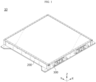
- FIG. 1 is a perspective view of a battery pack according to an embodiment of the present disclosure
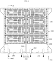
- FIG. 2 is an exploded perspective view of a battery pack according to an embodiment of the present disclosure
- FIG. 3 is a perspective view of a battery module according to an embodiment of the present disclosure.
- a battery pack 10 may include a battery module 100, a pack case 200, and a cartridge 300.
- the battery module 100 may include a plurality of battery cells 110.
- the battery cell 110 may be any type of secondary battery, such as a prismatic, cylindrical, or pouch-type battery cell.
- the present embodiment as shown in FIG. 3 , will be described based on the battery cell 110 that is a pouch-type battery cell.
- the present disclosure is not limited to a specific type or form of battery cell 110, and various battery cells 110 known at the time of filing the present disclosure may be used to constitute the battery module 100 of the present disclosure.
- the present embodiment shows a pouch-type secondary battery, which has high energy density and is easy to stack, by way of example as shown in the drawing, a cylindrical or prismatic secondary battery may be applied to the battery cell 110.
- the plurality of battery cells 110 may be arranged in columns and rows inside the battery module 100.
- the plurality of battery cells 110 may be arranged side by side in the left/right direction (the Y-axis direction) while standing in the vertical direction (the Z-axis direction).
- the battery pack 10 may have a plurality of battery modules 100 including a plurality of battery cells 110 described above.
- the plurality of battery modules 100 may be arranged in a row side by side in the horizontal direction (the X-axis direction and Y-axis direction).
- the battery pack 10 may include a pack case 200.
- the pack case 200 may be configured to accommodate the plurality of battery modules 100. The detailed structure of the pack case 200 will be described later.
- the battery pack 10 may include a cartridge 300.
- the cartridge 300 may be configured to store carbon dioxide therein.
- the carbon dioxide may be stored in a liquid state inside the cartridge 300 under high pressure.
- the cartridge 300 may be a commercially available product that is used to inflate tires of bicycles by injecting carbon dioxide.
- the cartridge 300 may be used along with an inflator or adapter.
- the cartridge 300 may be provided in the pack case 200.
- the cartridge 300 may be configured to release carbon dioxide stored therein to the outside of the pack case 200.
- carbon dioxide is heavier than oxygen, so when it is released into a combustible material, it forms an incombustible layer on the surface of the combustible material, thereby blocking the supply of oxygen, which is one of the elements that cause flame.
- carbon dioxide absorb a large amount of heat when evaporating because it has very high latent heat of evaporation. Therefore, in the event of a flame, carbon dioxide stored in a liquid state inside the cartridge 300 may be vaporized when released to the outside of the cartridge 300, thereby absorbing heat from the surrounding air to cool the same below the ignition point and extinguish the flame according thereto.
- the present embodiment shows carbon dioxide stored inside the cartridge 300, other fire extinguishing agents may be applied as well.
- the flame may be extinguished by carbon dioxide released from the cartridge 300 by removing heat, which is an element causing flame, thereby ensuring safety and reliability.
- the pack case 200 may include a base frame 210 and a side frame 220.
- the base frame 210 may be provided to constitute the lower surface of the pack case 200. Accordingly, the plurality of battery modules 100 may be seated on the base frame 210. In this implemented configuration, the base frame 210 may be configured in the form of a square plate.
- the side frame 220 may be provided to extend upward from the respective edges of the base frame 210.
- the side frame 220 may be provided to surround the plurality of battery modules 100.
- the side frame 220 may include walls extending in the X-axis direction and the Y-axis direction.
- At least a portion of the cartridge 300 may be coupled to the side frame 220 of the pack case 200.
- the cartridge 300 may be coupled to the side frame 220 in the -Y-axis direction.
- the cartridge 300 may be coupled to face the outside of the pack case 200.
- the pack case 200 may include a pack lid 230 configured to cover the top of the battery module 100.
- the battery module 100 may include a case body 120 and an end plate 130 disposed on the front and rear faces of the case body 120.
- the case body 120 may be configured in the shape of a square tube in a hollow structure having open ends O at both ends in the longitudinal direction and having an empty space therein.
- the case body 120 may be configured in the form of a tube that has an upper face, a lower face, a left face, and a right face, and has openings formed at the front and rear ends, respectively.
- the case body 120 may be formed in various other shapes.
- the case body 120 may be configured in a form in which a left plate, a right plate, and a bottom plate are integrated with each other.
- the integrated case part may be referred to as a U-frame.
- a top plate may be welded to the top of the U-frame, thereby configuring a tubular shape.
- the case body 120 may include a box-shaped lower case in which a left plate, a right plate, a front plate, and a rear plate are integrated with each other, and an upper cover that closes the top opening of the lower case.
- the case body 120 may be configured such that the battery cells 110 are able to be inserted thereinto in one direction.
- the battery cells 110 may be inserted into the case body 120 in the forward/backward direction (the X-axis direction). That is, the case body 120 may be configured to insert the battery cells 110 therein using a sliding or press-fitting manner.
- press-fitting there may be almost no gap between the upper and lower faces of the case body 120 and the upper and lower ends of the battery cells 110, and there may also be almost no gap between both side faces of the case body 120 and both side portions of the battery cells 110.
- This case body 120 may be made of a metal material with rigidity and heat resistance in order to physically or chemically protect the accommodated battery cells 110.
- the end plate 130 may be provided to be coupled to the open end O of the case body 120.
- the end plate 130 may have an inner side (facing the open end O) made of an insulating material and an outer side (constituting the exterior of the battery module 100) made of a metal material.
- the end plate 130 may have, at least in part, holes or slits through which positive and negative electrode terminals or connectors of the battery module 100 are exposed to the outside.
- FIG. 4 is a diagram illustrating the direction in which a cartridge operates in a battery pack according to an embodiment of the present disclosure
- FIG. 5 is a cross-sectional view taken along line A-A' in FIG. 4 .
- each of the plurality of battery modules 100 may include a thermistor 140.
- the thermistor 140 may be provided inside the battery module 100 and configured to measure the temperature of the battery module 100 and/or the temperature of venting gas generated from the battery module 100. It is possible to identify whether or not a flame has occurred through the temperature of gas measured by the thermistor 140.
- the thermistor 140 may be attached to the upper surface of the battery module 100 provided with the venting holes H and may measure the temperature of venting gas.
- the thermistor 140 may be provided at any position as long as it is able to measure the temperature of venting gas.
- carbon dioxide stored inside the cartridge 300 may be released to the outside of the pack case 200.
- a temperature rise rate of gas measured by the thermistor 140 reaches a second value, carbon dioxide stored inside the cartridge 300 may be released to the outside of the pack case 200.
- the temperature of the battery module 100 may be between 200°C and 300°C, and at the same time, the temperature of the battery module 100 may rise significantly. If the temperature of gas measured by the thermistor 140 is 200°C, that is, the first value and if the temperature rise rate of gas measured by the thermistor 140 is 1°C/second, that is, the second value, carbon dioxide may be released from the cartridge 300.
- the above-implemented configuration of the present disclosure it is possible to detect a risk of flame occurring before the venting gas generated from the battery cell 110 in the event of an abnormality in the battery cell 110 is discharged to the outside of the pack case 200, meets oxygen, and leads to a flame.
- FIG. 6 is a diagram illustrating the detailed structure of a cartridge according to an embodiment of the present disclosure.
- the cartridge 300 may include a cylinder unit 310.
- the cylinder unit 310 may include a storage portion 311 having a space for storing carbon dioxide therein, and a release portion 312 extending from the storage portion 311 to release carbon dioxide.
- the storage portion 311 may be coupled to the pack case 200, and in this case, the release portion 312 may be provided to protrude to the outside of the pack case 200.
- the diameter of the release portion 312 may be configured to be smaller than the diameter of the storage portion 311. Accordingly, if a flame occurs outside the pack case 200, carbon dioxide may be quickly released from the release portion 312.
- the release portion 312 may be made of a material with a lower melting point than the storage portion 311. The melting point of the release portion 312 may be similar to the temperature of flame, so that it melts and carbon dioxide is released when flame occurs. According to the above-implemented configuration of the present disclosure, it is possible to suppress the occurrence of flame by instantly purging and removing venting gas and oxygen, which are elements causing flame, using carbon dioxide rapidly released from the cartridge 300.
- FIG. 7 is a diagram illustrating the location of an operating unit of a cartridge according to an embodiment of the present disclosure.
- the cartridge 300 may further include an operating unit 320.
- the operating unit 320 may be connected to the cylinder unit 310 and may enable the cylinder unit 310 to release carbon dioxide if the temperature of gas measured by the thermistor 140 is equal to or greater than a first value and if a temperature rise rate is equal to or greater than a second value.
- the operating unit 320 may be provided in any configuration that allows carbon dioxide to be released from the cylinder unit 310.
- the operating unit 320 may be provided in a space between the side frame 220 and the plurality of battery modules 100.
- a plurality of cylinder units 310 may be provided, and a plurality of operating units 320 may be provided to be connected to the plurality of cylinder units 310, respectively.
- carbon dioxide may be released from a specific cylinder unit 310 depending on the location where flame occurs, thereby effectively suppressing or extinguishing the flame.
- FIG. 8 is a diagram illustrating the location of an operating unit of a cartridge according to another embodiment of the present disclosure.
- the pack case 200 may have a space in which the operating unit 320 is provided.
- a space in which the operating unit 320 is provided may be provided inside the side frame 220 or a cross-beam 250.
- the operating unit 320 may be configured to be connected to the cylinder units 310 provided on both sides of the cross-beam 250 and, if the temperature of gas measured by the thermistor 140 is equal to or greater than the first value and if a temperature rise rate is equal to or greater than the second value, enable several cylinder units 310 provided on both sides of the cross-beam 250 to release carbon dioxide.
- the operating unit 320 may be connected to at least one or more cylinder units 310, so that when a flame occurs at a specific location, several cylinder units 310 may simultaneously release carbon dioxide, thereby suppressing or extinguishing the flame more quickly.
- FIG. 9 is a diagram illustrating the location of a temperature sensor in a battery pack according to another embodiment of the present disclosure.
- a battery pack 10 may further include a temperature sensor 400.
- the temperature sensor 400 may be configured to measure the temperature of flame occurring outside the pack case 200. If the temperature of flame measured by the temperature sensor 400 reaches a third value, carbon dioxide stored inside the cartridge 300 may be released to the outside of the pack case 200.
- the temperature of the flame may reach 800°C to 1000°C, and if the temperature of flame measured by the temperature sensor 400 falls between 800°C to 1000°C, i.e., the third value, the cartridge 300 may release carbon dioxide.
- the temperature sensor 400 may be provided on the side frame 220 of the pack case 200.
- the temperature sensor 400 and the cartridge 300 may be provided side by side with each other. That is, the temperature sensor 400 may quickly identify whether or not a flame has occurred by directly measuring the temperature of the flame occurring outside the pack case 200.
- the temperature sensor 400 may quickly identify the occurrence of a flame, so that the cartridge 300 may operate to release carbon dioxide, thereby extinguishing the flame.
- the pack case 200 may include a venting device 240.
- the venting device 240 may be configured to discharge gas generated from the battery module 100 to the outside of the pack case 200 when an abnormal situation happens in the battery module 100. Specifically, venting gas emitted from the battery module 100 may be discharged to the outside of the pack case 200 through the venting device 240.
- sparks When gas is ejected from the battery cell 110, pieces of electrode plates or active materials inside the battery cell 110 may be heated to a high temperature and discharged to the outside, and these high-temperature particles may appear in the form of sparks. These sparks may be discharged to the outside of the pack case 200 through the venting device 240, and the sparks may react with oxygen outside the pack case 200 to generate a flame.
- the venting device 240 may be provided on the side frame 220 of the pack case 200. Although the venting device 240 is provided on the right wall (in the -Y-axis direction) in FIGS. 2 and 4 , it may also be provided on the wall in the +Y-axis direction. The venting device 240 may be provided on the side frame 220 in the respective rows in which the plurality of battery modules 100 is arranged. According to the above-implemented configuration of the present disclosure, in the event of an abnormality of the battery cell 110, high-temperature gas or sparks may be discharged in various directions of the pack case 200, so that the gas or the like may be easily discharged to the outside of the pack case 200.
- the pack case 200 may further include a cross-beam 250.
- the cross-beam 250 may be provided to connect at least portions of the side frame 220 to each other.
- the cross-beam 250 may be provided to extend in the Y-axis direction.
- the cross-beam 250 may partition the plurality of battery modules 100.
- a plurality of battery modules 100 may be arranged side by side on both sides of the cross-beam 250 inside the pack case 200.
- the plurality of units U may be symmetrically provided on both sides of the cross-beam 250 with respect to the side frame 220.
- the temperature sensor 400 may be provided between the venting device 240 and the cartridge 300. According to the implemented configuration of the present disclosure, even if high-temperature gas or sparks are emitted from any venting device 240 and lead to a flame, the temperature sensor 400 provided side by side with the venting device 240 may detect the temperature of the flame, and the cartridge 300 provided along with the venting device 240 may operate to quickly extinguish the flame.
- the pack case 200 may further include a partition 260.
- the partition 260 may be provided to separate the plurality of battery modules 100.
- the partition 260 may be configured to extend from the cross-beam 250.
- the partition 260 may be configured to extend from the cross-beam 250 in the X-axis direction.
- a plurality of partitions 260 may be provided to be spaced apart at regular intervals. According to the above-implemented configuration of the present disclosure, since the plurality of battery modules 100 are separated by the partition 260, even if an abnormal situation occurs in any one battery module 100, it is possible to prevent heat propagation to other battery modules 100.
- the vehicle 1 including the same may also have those effects.
- the battery pack 10 may suppress the occurrence of flame outside the pack case 200 by removing elements that may cause flame in the event of an abnormality in the battery cell 110 or battery module 100.
- the vehicle 1 including the battery pack 10 also has advantages in safety and reliability.
Landscapes
- Chemical & Material Sciences (AREA)
- Chemical Kinetics & Catalysis (AREA)
- Electrochemistry (AREA)
- General Chemical & Material Sciences (AREA)
- Engineering & Computer Science (AREA)
- Manufacturing & Machinery (AREA)
- Battery Mounting, Suspending (AREA)
- Aviation & Aerospace Engineering (AREA)
- Gas Exhaust Devices For Batteries (AREA)
- Secondary Cells (AREA)
Abstract
Description
- The present disclosure relates to a battery pack and a vehicle including the same. More specifically, it relates to a battery pack capable of suppressing or extinguishing flames occurring outside a pack case by detecting temperature, and a vehicle including the same.
- The present application claims priority to
Korean Patent Application No. 10-2023-0073813 filed on June 08, 2023 - Secondary batteries, which are easy to apply depending on the product group and have electrical features such as high energy density and the like, are generally used in electric vehicles (EVs) or hybrid electric vehicles (HEVs) that are driven by an electrical drive source, as well as in portable devices. These secondary batteries are attracting attention as a new energy source for improving eco-friendliness and energy efficiency because of the primary advantage of dramatically reducing the use of fossil fuels and another advantage of not generating by-products resulting from energy use.
- Current secondary batteries widely used include lithium-ion batteries, lithium-polymer batteries, nickel-cadmium batteries, nickel-hydrogen batteries, nickel-zinc batteries, and the like. If a higher output voltage is required, a battery module or battery pack may be configured by connecting a plurality of battery cells in series. In addition, a battery module or battery pack may be configured by connecting multiple battery cells in parallel in order to increase the charge/discharge capacity. Accordingly, the number of battery cells included in the battery module or battery pack may be set in various ways depending on the required output voltage or charge/discharge capacity.
- Meanwhile, a common method for configuring a battery pack by connecting a plurality of battery cells in series/parallel is to preferentially configure a battery module including at least one battery cell and then add other elements using the at least one battery module, thereby configuring a battery pack or battery rack.
- In the case of a conventional battery pack, the internal temperature may rise due to abnormalities or misuse of the battery cell, which may result in an increase in the internal pressure of the battery cell. Due to this internal pressure, high-temperature gas may vent from the battery cell, which is very dangerous because the high-temperature venting gas may spread to adjacent battery modules and cause thermal runaway.
- In addition, generally, when gas is ejected from the battery cell, pieces of electrode plates or active materials inside the battery cell may be heated to a high temperature and discharged to the outside, and these high-temperature particles may appear in the form of sparks.
- In this conventional battery pack, when an abnormal situation happens in a specific battery cell or battery module, high-temperature gas is discharged through a venting device, which is provided in the pack case to discharge the high-temperature gas to the outside of the pack case. At this time, if the sparks are discharged along with the gas to the outside, they may react with oxygen outside the battery pack, making a flame or developing into a fire. Furthermore, if a flame or fire occurs outside a specific battery pack, the fire or the like may spread to other adjacent battery packs or a device equipped with the battery pack, causing bigger problems such as explosion. In this case, if the flame occurring outside the battery pack is not extinguished early, it may spread to other adjacent battery modules inside the battery pack.
- Accordingly, if a thermal event occurs in a specific battery cell or battery module, the battery pack is required to remove fuel, oxygen, and heat, which are the elements that cause flame, thereby preventing the high-temperature gas or sparks from reacting with oxygen outside the battery pack and making a flame. In addition, even if a flame occurs, it is necessary to extinguish the flame early to prevent or delay propagation of the flame to other battery modules.
- The present disclosure has been designed to solve the problems of the related art, and therefore the present disclosure is directed to providing a battery pack capable of ensuring safety and reliability by suppressing flame from occurring outside the pack case in the event of an abnormality in the battery cell or battery module, and a vehicle including the same.
- However, the technical problems that the present disclosure seeks to solve are not limited to the above-mentioned problems, and other problems not mentioned above will be clearly understood by those skilled in the art from the description of the invention described below.
- According to one aspect of the present disclosure, there is provided a battery pack that includes a plurality of battery modules including a plurality of battery cells, a pack case configured to accommodate the plurality of battery modules, and a cartridge provided in the pack case and configured to release carbon dioxide stored therein to the outside of the pack case.
- The pack case may include a base frame configured to constitute the lower surface of the pack case and on which the plurality of battery modules is seated, and a side frame extending upward from the base frame to constitute an outer surface of the pack case, and at least a portion of the cartridge may be coupled to the side frame.
- Each of the plurality of battery modules may include a thermistor configured to measure the temperature of gas generated in the battery module, and if the temperature of gas measured by the thermistor is equal to or greater than a first value and if a temperature rise rate is equal to or greater than a second value, carbon dioxide stored inside the cartridge may be released to the outside of the pack case.
- For example, carbon dioxide may be released from the cartridge if the first value is 200°C and the second value is 1°C/sec.
- The cartridge may include a cylinder unit including a storage portion having a space for storing carbon dioxide therein and a release portion extending from the storage portion and configured to release carbon dioxide.
- The diameter of the release portion may be smaller than the diameter of the storage portion.
- The cartridge may further include an operating unit connected to the cylinder unit and configured to enable the cylinder unit to release carbon dioxide if the temperature measured by the thermistor is equal to or greater than the first value and if the temperature rise rate is equal to or greater than the second value.
- The operating unit may be provided in a space between the side frame and the plurality of battery modules.
- The pack case may have a space in which the operating unit is provided.
- The battery pack of the present disclosure may further include a temperature sensor configured to measure the temperature of flame occurring outside the pack case, and if the temperature of flame measured by the temperature sensor is a third value, carbon dioxide stored inside the cartridge may be released to the outside of the pack case.
- The temperature sensor may be provided on the side frame and configured to measure the temperature of flame.
- Carbon dioxide may be released from the cartridge if the third value is 800°C to 1000°C.
- The pack case may include a venting device provided on the side frame and configured to discharge gas generated in the battery module to the outside of the pack case, and the cartridge may be configured to release carbon dioxide stored therein to purge oxygen around the venting device.
- The cartridge may be disposed side by side with the venting device in the horizontal direction.
- A plurality of cartridges and a plurality of venting devices may be provided, and a plurality of units comprised of one or more cartridges and one venting device may be provided, and the plurality of units may be provided symmetrically with respect to the center of the side frame.
- The pack case may further include a cross-beam configured to connect at least portions of the side frame to each other and partition the plurality of battery modules, and the plurality of units may be symmetrically provided on both sides of the cross-beam.
- The pack case may further include a partition extending from the cross-beam and configured to partition the plurality of battery modules.
- In addition, the present disclosure also provides a vehicle including the battery pack according to the present disclosure.
- According to one aspect of the present disclosure, it is possible to ensure safety and reliability by suppressing the occurrence of flame outside the pack case by removing elements that may cause flame in the event of an abnormality in the battery cell or battery module.
- In addition, according to one aspect of the present disclosure, even if a flame occurs outside the pack case in the event of an abnormality in the battery cell or battery module, it is possible to extinguish the flame early, thereby preventing subsequent chain ignition.
- In addition, according to one aspect of the present disclosure, it is possible to maximally prevent thermal damage to other battery modules even if a flame occurs outside the pack case in the event of an abnormality in the battery cell or battery module, thereby effectively securing thermal propagation prevention performance in the pack.
- In addition, the present disclosure may have various other effects, and these will be described in the respective embodiments, or description of effects that may be easily inferred by those skilled in the art will be omitted.
- The accompanying drawings illustrate a preferred embodiment of the present disclosure and, together with the detailed description of the invention, serve to provide further understanding of the technical idea of the present disclosure, and thus, the present disclosure is not construed as being limited to the drawings.
-
FIG. 1 is a perspective view of a battery pack according to an embodiment of the present disclosure. -
FIG. 2 is an exploded perspective view of a battery pack according to an embodiment of the present disclosure. -
FIG. 3 is a perspective view of a battery module according to an embodiment of the present disclosure. -
FIG. 4 is a diagram illustrating the direction in which a cartridge operates in a battery pack according to an embodiment of the present disclosure. -
FIG. 5 is a cross-sectional view taken along line A-A' inFIG. 4 . -
FIG. 6 is a diagram illustrating the detailed structure of a cartridge according to an embodiment of the present disclosure. -
FIG. 7 is a diagram illustrating the location of an operating unit of a cartridge according to an embodiment of the present disclosure. -
FIG. 8 is a diagram illustrating the location of an operating unit of a cartridge according to another embodiment of the present disclosure. -
FIG. 9 is a diagram illustrating the location of a temperature sensor in a battery pack according to another embodiment of the present disclosure. -
FIG. 10 is a perspective view of a vehicle including a battery pack according to an embodiment of the present disclosure. - Hereinafter, preferred embodiments of the present disclosure will be described in detail with reference to the accompanying drawings. Prior to the description, it should be understood that the terms used in the specification and the appended claims should not be construed as limited to general and dictionary meanings, but interpreted based on the meanings and concepts corresponding to technical aspects of the present disclosure on the basis of the principle that the inventor is allowed to define terms appropriately for the best explanation.
- Therefore, the configurations proposed in the embodiments and drawings of this specification indicate only the most preferable embodiment of the present disclosure and do not represent all technical ideas of the present disclosure, so it should be understood that various equivalents and modifications could be made thereto at the time of filing the application.
- The sizes of respective elements or specific parts of each element shown in the attached drawings are exaggerated, omitted, or simplified for convenience of explanation and clarification thereof. Accordingly, the sizes of respective elements do not entirely reflect their actual sizes. Descriptions of related known functions or configurations, which may obscure the subject matter of the present disclosure, will be omitted. For reference, in this specification, terms indicating directions are based on the elements shown in the attached drawings, and are relative terms that may vary depending on the postures or positions of the actual elements.
- Meanwhile, although terms indicating directions such as upward, downward, left, right, forward, and backward directions are used in this specification, it is obvious to those skilled in the art that these terms are only for convenience of explanation and may vary depending on the position of the target object or the position of the observer.
- For example, in the embodiment of the present disclosure, the X-axis direction shown in the drawing may indicate the forward/backward direction, the Y-axis direction may indicate the left/right direction perpendicular to the X-axis direction on the flat plane (X-Y plane), and the Z-axis direction may indicate the upward/downward direction (vertical direction) perpendicular to both the X-axis direction and the Y-axis direction.
-
FIG. 1 is a perspective view of a battery pack according to an embodiment of the present disclosure,FIG. 2 is an exploded perspective view of a battery pack according to an embodiment of the present disclosure, andFIG. 3 is a perspective view of a battery module according to an embodiment of the present disclosure. - Referring to
FIGS. 1 and2 , abattery pack 10 according to an embodiment of the present disclosure may include abattery module 100, apack case 200, and acartridge 300. - The
battery module 100 may include a plurality ofbattery cells 110. Thebattery cell 110 may be any type of secondary battery, such as a prismatic, cylindrical, or pouch-type battery cell. The present embodiment, as shown inFIG. 3 , will be described based on thebattery cell 110 that is a pouch-type battery cell. - The present disclosure is not limited to a specific type or form of
battery cell 110, andvarious battery cells 110 known at the time of filing the present disclosure may be used to constitute thebattery module 100 of the present disclosure. Although the present embodiment shows a pouch-type secondary battery, which has high energy density and is easy to stack, by way of example as shown in the drawing, a cylindrical or prismatic secondary battery may be applied to thebattery cell 110. - The plurality of
battery cells 110 may be arranged in columns and rows inside thebattery module 100. For example, as shown inFIG. 3 , the plurality ofbattery cells 110 may be arranged side by side in the left/right direction (the Y-axis direction) while standing in the vertical direction (the Z-axis direction). - The
battery pack 10 may have a plurality ofbattery modules 100 including a plurality ofbattery cells 110 described above. For example, as shown inFIG. 2 , the plurality ofbattery modules 100 may be arranged in a row side by side in the horizontal direction (the X-axis direction and Y-axis direction). - The
battery pack 10 according to an embodiment of the present disclosure may include apack case 200. Thepack case 200 may be configured to accommodate the plurality ofbattery modules 100. The detailed structure of thepack case 200 will be described later. - The
battery pack 10 according to an embodiment of the present disclosure may include acartridge 300. Thecartridge 300 may be configured to store carbon dioxide therein. The carbon dioxide may be stored in a liquid state inside thecartridge 300 under high pressure. For example, thecartridge 300 may be a commercially available product that is used to inflate tires of bicycles by injecting carbon dioxide. Thecartridge 300 may be used along with an inflator or adapter. - The
cartridge 300 may be provided in thepack case 200. Thecartridge 300 may be configured to release carbon dioxide stored therein to the outside of thepack case 200. - Specifically, carbon dioxide is heavier than oxygen, so when it is released into a combustible material, it forms an incombustible layer on the surface of the combustible material, thereby blocking the supply of oxygen, which is one of the elements that cause flame. In addition, carbon dioxide absorb a large amount of heat when evaporating because it has very high latent heat of evaporation. Therefore, in the event of a flame, carbon dioxide stored in a liquid state inside the
cartridge 300 may be vaporized when released to the outside of thecartridge 300, thereby absorbing heat from the surrounding air to cool the same below the ignition point and extinguish the flame according thereto. Although the present embodiment shows carbon dioxide stored inside thecartridge 300, other fire extinguishing agents may be applied as well. - According to the above-implemented configuration of the present disclosure, it is possible to ensure safety and reliability by blocking the supply of oxygen, which is an element causing flame, and suppressing the occurrence of flames outside the
pack case 200 according thereto. - In addition, according to the above-implemented configuration of the present disclosure, even if a flame occurs outside the
pack case 200, the flame may be extinguished by carbon dioxide released from thecartridge 300 by removing heat, which is an element causing flame, thereby ensuring safety and reliability. - Meanwhile, referring to
FIG. 2 , thepack case 200 may include abase frame 210 and aside frame 220. - The
base frame 210 may be provided to constitute the lower surface of thepack case 200. Accordingly, the plurality ofbattery modules 100 may be seated on thebase frame 210. In this implemented configuration, thebase frame 210 may be configured in the form of a square plate. - The
side frame 220 may be provided to extend upward from the respective edges of thebase frame 210. Theside frame 220 may be provided to surround the plurality ofbattery modules 100. For example, in this implemented configuration, theside frame 220 may include walls extending in the X-axis direction and the Y-axis direction. - At least a portion of the
cartridge 300 may be coupled to theside frame 220 of thepack case 200. For example, as shown inFIG. 2 , at least a portion of thecartridge 300 may be coupled to theside frame 220 in the -Y-axis direction. In this case, thecartridge 300 may be coupled to face the outside of thepack case 200. - In addition, referring to
FIG. 2 , thepack case 200 may include apack lid 230 configured to cover the top of thebattery module 100. - Meanwhile, the detailed structure of the
battery module 100 according to an embodiment of the present disclosure will be described with reference toFIG. 3 . Thebattery module 100 according to the present embodiment may include acase body 120 and anend plate 130 disposed on the front and rear faces of thecase body 120. - The
case body 120 may be configured in the shape of a square tube in a hollow structure having open ends O at both ends in the longitudinal direction and having an empty space therein. For example, thecase body 120 may be configured in the form of a tube that has an upper face, a lower face, a left face, and a right face, and has openings formed at the front and rear ends, respectively. - In addition, the
case body 120 may be formed in various other shapes. For example, thecase body 120 may be configured in a form in which a left plate, a right plate, and a bottom plate are integrated with each other. In this case, the integrated case part may be referred to as a U-frame. A top plate may be welded to the top of the U-frame, thereby configuring a tubular shape. Alternatively, thecase body 120 may include a box-shaped lower case in which a left plate, a right plate, a front plate, and a rear plate are integrated with each other, and an upper cover that closes the top opening of the lower case. - In addition, the
case body 120 may be configured such that thebattery cells 110 are able to be inserted thereinto in one direction. For example, thebattery cells 110 may be inserted into thecase body 120 in the forward/backward direction (the X-axis direction). That is, thecase body 120 may be configured to insert thebattery cells 110 therein using a sliding or press-fitting manner. For press-fitting, there may be almost no gap between the upper and lower faces of thecase body 120 and the upper and lower ends of thebattery cells 110, and there may also be almost no gap between both side faces of thecase body 120 and both side portions of thebattery cells 110. - This
case body 120 may be made of a metal material with rigidity and heat resistance in order to physically or chemically protect the accommodatedbattery cells 110. - Meanwhile, a venting hole H may be provided on the
case body 120, enabling directional venting in one direction. For example, as shown inFIG. 3 , a plurality of venting holes H may be formed on the upper face of thecase body 120, so that directional venting in the upward direction of thebattery module 100 may be performed through the venting holes H. Specifically, high-temperature gas discharged from thebattery cell 110 through the venting holes H may be discharged to the outside of thepack case 200 through theventing device 300. - The
end plate 130 may be provided to be coupled to the open end O of thecase body 120. For example, theend plate 130 may have an inner side (facing the open end O) made of an insulating material and an outer side (constituting the exterior of the battery module 100) made of a metal material. In addition, theend plate 130 may have, at least in part, holes or slits through which positive and negative electrode terminals or connectors of thebattery module 100 are exposed to the outside. -
FIG. 4 is a diagram illustrating the direction in which a cartridge operates in a battery pack according to an embodiment of the present disclosure, andFIG. 5 is a cross-sectional view taken along line A-A' inFIG. 4 . - Referring to
FIGS. 3 to 5 , each of the plurality ofbattery modules 100 according to an embodiment of the present disclosure may include athermistor 140. - The
thermistor 140 may be provided inside thebattery module 100 and configured to measure the temperature of thebattery module 100 and/or the temperature of venting gas generated from thebattery module 100. It is possible to identify whether or not a flame has occurred through the temperature of gas measured by thethermistor 140. For example, as shown inFIG. 3 , thethermistor 140 according to an embodiment may be attached to the upper surface of thebattery module 100 provided with the venting holes H and may measure the temperature of venting gas. However, thethermistor 140 may be provided at any position as long as it is able to measure the temperature of venting gas. - Specifically, in an embodiment of the present disclosure, if the temperature of gas measured by the
thermistor 140 reaches a first value, carbon dioxide stored inside thecartridge 300 may be released to the outside of thepack case 200. In addition, if a temperature rise rate of gas measured by thethermistor 140 reaches a second value, carbon dioxide stored inside thecartridge 300 may be released to the outside of thepack case 200. - For example, in the event of an abnormality in the
battery cell 110 orbattery module 100, the temperature of thebattery module 100 may be between 200°C and 300°C, and at the same time, the temperature of thebattery module 100 may rise significantly. If the temperature of gas measured by thethermistor 140 is 200°C, that is, the first value and if the temperature rise rate of gas measured by thethermistor 140 is 1°C/second, that is, the second value, carbon dioxide may be released from thecartridge 300. - According to the above-implemented configuration of the present disclosure, it is possible to detect a risk of flame occurring before the venting gas generated from the
battery cell 110 in the event of an abnormality in thebattery cell 110 is discharged to the outside of thepack case 200, meets oxygen, and leads to a flame. In addition, according to the above-implemented configuration of the present disclosure, it is possible to prevent flame from occurring by blocking the supply of oxygen, which is the element causing flame, in advance. -
FIG. 6 is a diagram illustrating the detailed structure of a cartridge according to an embodiment of the present disclosure. - The
cartridge 300 may include acylinder unit 310. Thecylinder unit 310 may include astorage portion 311 having a space for storing carbon dioxide therein, and arelease portion 312 extending from thestorage portion 311 to release carbon dioxide. As shown inFIG. 5 , thestorage portion 311 may be coupled to thepack case 200, and in this case, therelease portion 312 may be provided to protrude to the outside of thepack case 200. - The diameter of the
release portion 312 may be configured to be smaller than the diameter of thestorage portion 311. Accordingly, if a flame occurs outside thepack case 200, carbon dioxide may be quickly released from therelease portion 312. Therelease portion 312 may be made of a material with a lower melting point than thestorage portion 311. The melting point of therelease portion 312 may be similar to the temperature of flame, so that it melts and carbon dioxide is released when flame occurs. According to the above-implemented configuration of the present disclosure, it is possible to suppress the occurrence of flame by instantly purging and removing venting gas and oxygen, which are elements causing flame, using carbon dioxide rapidly released from thecartridge 300. -
FIG. 7 is a diagram illustrating the location of an operating unit of a cartridge according to an embodiment of the present disclosure. - Meanwhile, the
cartridge 300 may further include anoperating unit 320. Theoperating unit 320 may be connected to thecylinder unit 310 and may enable thecylinder unit 310 to release carbon dioxide if the temperature of gas measured by thethermistor 140 is equal to or greater than a first value and if a temperature rise rate is equal to or greater than a second value. Theoperating unit 320 may be provided in any configuration that allows carbon dioxide to be released from thecylinder unit 310. - According to the implemented configuration of
FIG. 7 , theoperating unit 320 may be provided in a space between theside frame 220 and the plurality ofbattery modules 100. For example, a plurality ofcylinder units 310 may be provided, and a plurality of operatingunits 320 may be provided to be connected to the plurality ofcylinder units 310, respectively. According to the above-implemented configuration of the present disclosure, since the plurality of operatingunits 320 is respectively connected to the plurality ofcylinder units 310, carbon dioxide may be released from aspecific cylinder unit 310 depending on the location where flame occurs, thereby effectively suppressing or extinguishing the flame. -
FIG. 8 is a diagram illustrating the location of an operating unit of a cartridge according to another embodiment of the present disclosure. - The
pack case 200 may have a space in which theoperating unit 320 is provided. A space in which theoperating unit 320 is provided may be provided inside theside frame 220 or across-beam 250. For example, in the case where a space for installing theoperating unit 320 is provided inside thecross-beam 250 as shown inFIG. 8 , theoperating unit 320 may be configured to be connected to thecylinder units 310 provided on both sides of thecross-beam 250 and, if the temperature of gas measured by thethermistor 140 is equal to or greater than the first value and if a temperature rise rate is equal to or greater than the second value, enableseveral cylinder units 310 provided on both sides of the cross-beam 250 to release carbon dioxide. - According to the above-implemented configuration of the present disclosure, the
operating unit 320 may be connected to at least one ormore cylinder units 310, so that when a flame occurs at a specific location,several cylinder units 310 may simultaneously release carbon dioxide, thereby suppressing or extinguishing the flame more quickly. -
FIG. 9 is a diagram illustrating the location of a temperature sensor in a battery pack according to another embodiment of the present disclosure. - Referring to
FIG. 9 , abattery pack 10 according to another embodiment of the present disclosure may further include atemperature sensor 400. Thetemperature sensor 400 may be configured to measure the temperature of flame occurring outside thepack case 200. If the temperature of flame measured by thetemperature sensor 400 reaches a third value, carbon dioxide stored inside thecartridge 300 may be released to the outside of thepack case 200. - For example, when a flame occurs, the temperature of the flame may reach 800°C to 1000°C, and if the temperature of flame measured by the
temperature sensor 400 falls between 800°C to 1000°C, i.e., the third value, thecartridge 300 may release carbon dioxide. - The
temperature sensor 400 may be provided on theside frame 220 of thepack case 200. For example, thetemperature sensor 400 and thecartridge 300 may be provided side by side with each other. That is, thetemperature sensor 400 may quickly identify whether or not a flame has occurred by directly measuring the temperature of the flame occurring outside thepack case 200. - Even if the temperature of gas measured by the
thermistor 140 is equal to or less than the first value or even if the temperature rise rate is equal to or greater than the second value, a flame may occur outside thepack case 200. According to the above-implemented configuration of the present disclosure, even in such a case, thetemperature sensor 400 may quickly identify the occurrence of a flame, so that thecartridge 300 may operate to release carbon dioxide, thereby extinguishing the flame. - Meanwhile, referring to
FIGS. 1 to 9 , thepack case 200 may include aventing device 240. Theventing device 240 may be configured to discharge gas generated from thebattery module 100 to the outside of thepack case 200 when an abnormal situation happens in thebattery module 100. Specifically, venting gas emitted from thebattery module 100 may be discharged to the outside of thepack case 200 through theventing device 240. - When gas is ejected from the
battery cell 110, pieces of electrode plates or active materials inside thebattery cell 110 may be heated to a high temperature and discharged to the outside, and these high-temperature particles may appear in the form of sparks. These sparks may be discharged to the outside of thepack case 200 through theventing device 240, and the sparks may react with oxygen outside thepack case 200 to generate a flame. - At this time, the
cartridge 300 may be configured to release carbon dioxide stored therein to purge oxygen around theventing device 240. According to the above-implemented configuration of the present disclosure, it is possible to prevent high-temperature gas or sparks from reacting with oxygen and making flame outside the battery pack by removing oxygen, which is one of the elements that cause flame, when a thermal event occurs in aspecific battery cell 110 orbattery module 100. In addition, according to the above-implemented configuration of the present disclosure, even if a flame occurs, the flame may be suppressed early to prevent the flame from spreading to the plurality of battery modules inside the pack case. - The
venting device 240 may be provided on theside frame 220 of thepack case 200. Although theventing device 240 is provided on the right wall (in the -Y-axis direction) inFIGS. 2 and4 , it may also be provided on the wall in the +Y-axis direction. Theventing device 240 may be provided on theside frame 220 in the respective rows in which the plurality ofbattery modules 100 is arranged. According to the above-implemented configuration of the present disclosure, in the event of an abnormality of thebattery cell 110, high-temperature gas or sparks may be discharged in various directions of thepack case 200, so that the gas or the like may be easily discharged to the outside of thepack case 200. - The
cartridge 300 may be disposed side by side with theventing device 240 in a horizontal or vertical direction. For example, as shown inFIGS. 3 and5 , thecartridge 300 may be disposed side by side with theventing device 240 in the horizontal direction (X-axis direction). According to the above-implemented configuration of the present disclosure, if oxygen reacts with high-temperature gas or sparks discharged through theventing device 240 in the event of an abnormality in thebattery cell 110, leading to a flame, carbon dioxide may be released from thecartridge 300 provided side by side with theventing device 240, thereby quickly extinguishing the flame. - Referring to
FIG. 2 , a plurality ofcartridges 300 and a plurality of ventingdevices 240 may be provided. In addition, a plurality of units U comprised of one ormore cartridges 300 and oneventing device 240 may be provided. AlthoughFIG. 2 shows an embodiment in which each unit U includes oneventing device 240 and onecartridge 300, oneventing device 240 and a plurality ofcartridges 300 may also be provided. - Each of the plurality of units U may be provided on the
side frame 220 of thepack case 200. In this case, the plurality of units U may be provided symmetrically with respect to the center of theside frame 220. According to the above-implemented configuration of the present disclosure, it is easy to suppress or extinguish flame by carbon dioxide released from thecartridge 300 included in the unit U corresponding to the location of the gas or spark discharged to the outside of thepack case 200. - Meanwhile, as shown in
FIGS. 2 and4 , thepack case 200 may further include across-beam 250. Thecross-beam 250 may be provided to connect at least portions of theside frame 220 to each other. For example, as shown inFIG. 2 , thecross-beam 250 may be provided to extend in the Y-axis direction. In this case, thecross-beam 250 may partition the plurality ofbattery modules 100. A plurality ofbattery modules 100 may be arranged side by side on both sides of thecross-beam 250 inside thepack case 200. In this case, the plurality of units U may be symmetrically provided on both sides of the cross-beam 250 with respect to theside frame 220. - Meanwhile, in the case where the
battery pack 10 of the present disclosure further includes thetemperature sensor 400, as shown inFIG. 9 , thetemperature sensor 400 may be provided between the ventingdevice 240 and thecartridge 300. According to the implemented configuration of the present disclosure, even if high-temperature gas or sparks are emitted from anyventing device 240 and lead to a flame, thetemperature sensor 400 provided side by side with theventing device 240 may detect the temperature of the flame, and thecartridge 300 provided along with theventing device 240 may operate to quickly extinguish the flame. - In addition, the
pack case 200 may further include apartition 260. Thepartition 260 may be provided to separate the plurality ofbattery modules 100. Thepartition 260 may be configured to extend from thecross-beam 250. For example, as shown inFIG. 2 , thepartition 260 may be configured to extend from thecross-beam 250 in the X-axis direction. A plurality ofpartitions 260 may be provided to be spaced apart at regular intervals. According to the above-implemented configuration of the present disclosure, since the plurality ofbattery modules 100 are separated by thepartition 260, even if an abnormal situation occurs in any onebattery module 100, it is possible to prevent heat propagation toother battery modules 100. -
FIG. 10 is a perspective view of a vehicle including a battery pack according to an embodiment of the present disclosure. - Referring to
FIG. 10 , avehicle 1 according to an embodiment of the present disclosure may include one or more battery packs 10 according to an embodiment of the present disclosure. Thevehicle 1 according to the present disclosure may be, for example, an electric vehicle, a hybrid vehicle, or a plug-in hybrid vehicle. Thevehicle 1 includes a four-wheeled vehicle and a two-wheeled vehicle. Thevehicle 1 operates by receiving power from thebattery pack 10 according to an embodiment of the present disclosure. - Since the
battery pack 10 has the various effects mentioned above, thevehicle 1 including the same may also have those effects. Specifically, thebattery pack 10 may suppress the occurrence of flame outside thepack case 200 by removing elements that may cause flame in the event of an abnormality in thebattery cell 110 orbattery module 100. In addition, it is possible to prevent subsequent chain ignition by early extinguishing flame occurring outside of thepack case 200 in the event of an abnormality in thebattery cell 110 orbattery module 100, and effectively secure thermal propagation prevention performance in a pack by maximally preventing thermal damage toother battery modules 100. Accordingly, thevehicle 1 including thebattery pack 10 also has advantages in safety and reliability. - As described above, although the present disclosure has been described with reference to limited embodiments and drawings, the present disclosure is not limited thereto, and various modifications and variations are possible within the technical idea of the present disclosure and the scope of equivalence of the claims to be described below by those skilled in the art to which the present disclosure pertains.
Claims (18)
- A battery pack comprising:a plurality of battery modules comprising a plurality of battery cells;a pack case configured to accommodate the plurality of battery modules; anda cartridge provided in the pack case and configured to release carbon dioxide stored therein to the outside of the pack case.
- The battery pack according to claim 1,wherein the pack case comprisesa base frame configured to constitute the lower surface of the pack case and on which the plurality of battery modules is seated, anda side frame extending upward from the base frame to constitute an outer surface of the pack case, andwherein at least a portion of the cartridge is coupled to the side frame.
- The battery pack according to claim 2,wherein each of the plurality of battery modules comprises a thermistor configured to measure the temperature of gas generated in the battery module, andwherein if the temperature of gas measured by the thermistor is equal to or greater than a first value and if a temperature rise rate is equal to or greater than a second value, carbon dioxide stored inside the cartridge is released to the outside of the pack case.
- The battery pack according to claim 3,
wherein carbon dioxide is released from the cartridge if the first value is 200°C and the second value is 1°C/sec. - The battery pack according to claim 3,wherein the cartridge comprisesa cylinder unit comprising a storage portion having a space for storing carbon dioxide therein and a release portion extending from the storage portion and configured to release carbon dioxide.
- The battery pack according to claim 5,
wherein the diameter of the release portion is smaller than the diameter of the storage portion. - The battery pack according to claim 5,wherein the cartridge further comprisesan operating unit connected to the cylinder unit and configured to enable the cylinder unit to release carbon dioxide if the temperature measured by the thermistor is equal to or greater than the first value and if the temperature rise rate is equal to or greater than the second value.
- The battery pack according to claim 7,
wherein the operating unit is provided in a space between the side frame and the plurality of battery modules. - The battery pack according to claim 8,
wherein the pack case has a space in which the operating unit is provided. - The battery pack according to claim 3,further comprising a temperature sensor configured to measure the temperature of flame occurring outside the pack case, andwherein if the temperature of flame measured by the temperature sensor is a third value, carbon dioxide stored inside the cartridge is released to the outside of the pack case.
- The battery pack according to claim 10,
wherein the temperature sensor is provided on the side frame and configured to measure the temperature of flame. - The battery pack according to claim 11,
wherein the carbon dioxide is released from the cartridge if the third value is 800°C to 1000°C. - The battery pack according to claim 10,wherein the pack case comprisesa venting device provided on the side frame and configured to discharge gas generated in the battery module to the outside of the pack case, andwherein the cartridge is configured to release carbon dioxide stored therein to purge oxygen around the venting device.
- The battery pack according to claim 13,
wherein the cartridge is disposed side by side with the venting device in the horizontal direction. - The battery pack according to claim 14,wherein a plurality of cartridges and a plurality of venting devices are provided,wherein a plurality of units comprised of one or more cartridges and one venting device is provided, andwherein the plurality of units is provided symmetrically with respect to the center of the side frame.
- The battery pack according to claim 15,wherein the pack case further comprisesa cross-beam configured to connect at least portions of the side frame to each other and separate the plurality of battery modules, andwherein the plurality of units is symmetrically provided on both sides of the cross-beam.
- The battery pack according to claim 16,wherein the pack casefurther comprise a partition extending from the cross-beam and configured to separate the plurality of battery modules.
- A vehicle comprising the battery pack according to any one of claims 1 to 17.
Applications Claiming Priority (2)
| Application Number | Priority Date | Filing Date | Title |
|---|---|---|---|
| KR1020230073813A KR20240174410A (en) | 2023-06-08 | 2023-06-08 | Battery pack and vehicle including the same |
| PCT/KR2024/001763 WO2024253291A1 (en) | 2023-06-08 | 2024-02-06 | Battery pack and vehicle comprising same |
Publications (2)
| Publication Number | Publication Date |
|---|---|
| EP4550520A1 true EP4550520A1 (en) | 2025-05-07 |
| EP4550520A4 EP4550520A4 (en) | 2025-11-05 |
Family
ID=93795624
Family Applications (1)
| Application Number | Title | Priority Date | Filing Date |
|---|---|---|---|
| EP24819445.8A Pending EP4550520A4 (en) | 2023-06-08 | 2024-02-06 | BATTERY PACK AND VEHICLE WITH IT |
Country Status (5)
| Country | Link |
|---|---|
| EP (1) | EP4550520A4 (en) |
| JP (1) | JP2026511359A (en) |
| KR (1) | KR20240174410A (en) |
| CN (1) | CN119731838A (en) |
| WO (1) | WO2024253291A1 (en) |
Family Cites Families (9)
| Publication number | Priority date | Publication date | Assignee | Title |
|---|---|---|---|---|
| US7270910B2 (en) * | 2003-10-03 | 2007-09-18 | Black & Decker Inc. | Thermal management systems for battery packs |
| DE102013006758A1 (en) * | 2013-04-19 | 2014-10-23 | Daimler Ag | Battery assembly and method of operating a battery assembly |
| JP6586524B2 (en) * | 2016-06-10 | 2019-10-02 | ヤマトプロテック株式会社 | Electrochemical equipment using aerosol fire extinguishing device |
| KR102942238B1 (en) * | 2020-07-02 | 2026-03-23 | 주식회사 엘지에너지솔루션 | Battery pack comprising fire extinguishing apparatus |
| KR102952450B1 (en) * | 2020-09-28 | 2026-04-14 | 주식회사 엘지에너지솔루션 | Battery pack for fire safety |
| KR102857913B1 (en) * | 2021-06-17 | 2025-09-09 | 주식회사 엘지에너지솔루션 | Battery module with improved venting performance |
| KR20230073813A (en) | 2021-11-19 | 2023-05-26 | 최승진 | Ferrule and golf club |
| CN218391936U (en) * | 2021-11-29 | 2023-01-31 | 长城汽车股份有限公司 | Fire extinguishing box, battery package and vehicle |
| KR102531125B1 (en) * | 2022-06-23 | 2023-05-10 | 주식회사 티팩토리 | Battery energy storage system with extinguishing function |
-
2023
- 2023-06-08 KR KR1020230073813A patent/KR20240174410A/en active Pending
-
2024
- 2024-02-06 WO PCT/KR2024/001763 patent/WO2024253291A1/en not_active Ceased
- 2024-02-06 JP JP2025548337A patent/JP2026511359A/en active Pending
- 2024-02-06 EP EP24819445.8A patent/EP4550520A4/en active Pending
- 2024-02-06 CN CN202480003721.XA patent/CN119731838A/en active Pending
Also Published As
| Publication number | Publication date |
|---|---|
| JP2026511359A (en) | 2026-04-14 |
| WO2024253291A1 (en) | 2024-12-12 |
| CN119731838A (en) | 2025-03-28 |
| KR20240174410A (en) | 2024-12-17 |
| EP4550520A4 (en) | 2025-11-05 |
Similar Documents
| Publication | Publication Date | Title |
|---|---|---|
| CN110574189B (en) | Battery module and battery pack including the same | |
| KR20120108677A (en) | Pouch type secondary battery with gas exhaust device and control method of gas exhaust | |
| KR102944472B1 (en) | Battery pack, energy storage system and vehicle comprising the battery pack | |
| JP2025514782A (en) | Battery module and battery pack including same | |
| JP2024546809A (en) | Battery pack, battery module and automobile including same | |
| JP7741324B2 (en) | Battery cell unit, battery pack including same, and automobile | |
| KR102949021B1 (en) | Battery pack and vehicle including the same | |
| KR102956627B1 (en) | Battery module and Battery Pack including the same | |
| JP7775447B2 (en) | Battery module, battery pack including the battery module, energy storage device including the battery pack, and automobile | |
| US20250174806A1 (en) | Battery module with enhanced flame path and battery pack including same | |
| EP4475301A1 (en) | Battery module having compartment plate part and battery pack including same | |
| EP4672419A1 (en) | BATTERY BLOCK AND VEHICLE CONTAINING IT | |
| EP4664599A1 (en) | Battery module, battery pack, and vehicle comprising same | |
| KR20240174410A (en) | Battery pack and vehicle including the same | |
| EP4738569A1 (en) | Battery pack and vehicle including same | |
| EP4730487A1 (en) | Battery module, and battery pack and vehicle including same | |
| EP4579919A1 (en) | Battery module and battery pack including same | |
| EP4632922A1 (en) | Battery module and battery pack with reinforced safety | |
| EP4734262A1 (en) | Battery module | |
| EP4579920A1 (en) | Battery module having flame emission blocking unit and battery pack including same | |
| EP4708535A1 (en) | Battery module, battery pack, and vehicle | |
| EP4700951A1 (en) | Battery module | |
| JP2025541850A (en) | Battery module, battery pack including same, and automobile | |
| KR20250120886A (en) | Battery module and battery pack including the same and vehicle including the same | |
| KR20250120887A (en) | Battery module and battery pack including the same and vehicle including the same |
Legal Events
| Date | Code | Title | Description |
|---|---|---|---|
| STAA | Information on the status of an ep patent application or granted ep patent |
Free format text: STATUS: THE INTERNATIONAL PUBLICATION HAS BEEN MADE |
|
| PUAI | Public reference made under article 153(3) epc to a published international application that has entered the european phase |
Free format text: ORIGINAL CODE: 0009012 |
|
| STAA | Information on the status of an ep patent application or granted ep patent |
Free format text: STATUS: REQUEST FOR EXAMINATION WAS MADE |
|
| 17P | Request for examination filed |
Effective date: 20250129 |
|
| AK | Designated contracting states |
Kind code of ref document: A1 Designated state(s): AL AT BE BG CH CY CZ DE DK EE ES FI FR GB GR HR HU IE IS IT LI LT LU LV MC ME MK MT NL NO PL PT RO RS SE SI SK SM TR |
|
| A4 | Supplementary search report drawn up and despatched |
Effective date: 20251009 |
|
| RIC1 | Information provided on ipc code assigned before grant |
Ipc: H01M 10/42 20060101AFI20251002BHEP Ipc: H01M 10/48 20060101ALI20251002BHEP Ipc: H01M 50/383 20210101ALI20251002BHEP Ipc: H01M 50/289 20210101ALI20251002BHEP Ipc: H01M 50/249 20210101ALI20251002BHEP Ipc: H01M 50/204 20210101ALI20251002BHEP Ipc: H01M 50/367 20210101ALI20251002BHEP Ipc: H01M 50/30 20210101ALI20251002BHEP |
|
| STAA | Information on the status of an ep patent application or granted ep patent |
Free format text: STATUS: EXAMINATION IS IN PROGRESS |
|
| 17Q | First examination report despatched |
Effective date: 20260330 |