EP4550503A1 - Lithium battery - Google Patents
Lithium battery Download PDFInfo
- Publication number
- EP4550503A1 EP4550503A1 EP24201668.1A EP24201668A EP4550503A1 EP 4550503 A1 EP4550503 A1 EP 4550503A1 EP 24201668 A EP24201668 A EP 24201668A EP 4550503 A1 EP4550503 A1 EP 4550503A1
- Authority
- EP
- European Patent Office
- Prior art keywords
- lithium battery
- disposed
- mounting groove
- sheet
- battery according
- Prior art date
- Legal status (The legal status is an assumption and is not a legal conclusion. Google has not performed a legal analysis and makes no representation as to the accuracy of the status listed.)
- Pending
Links
Images

Classifications
-
- H—ELECTRICITY
- H01—ELECTRIC ELEMENTS
- H01M—PROCESSES OR MEANS, e.g. BATTERIES, FOR THE DIRECT CONVERSION OF CHEMICAL ENERGY INTO ELECTRICAL ENERGY
- H01M50/00—Constructional details or processes of manufacture of the non-active parts of electrochemical cells other than fuel cells, e.g. hybrid cells
- H01M50/60—Arrangements or processes for filling or topping-up with liquids; Arrangements or processes for draining liquids from casings
- H01M50/609—Arrangements or processes for filling with liquid, e.g. electrolytes
- H01M50/627—Filling ports
- H01M50/636—Closing or sealing filling ports, e.g. using lids
-
- H—ELECTRICITY
- H01—ELECTRIC ELEMENTS
- H01M—PROCESSES OR MEANS, e.g. BATTERIES, FOR THE DIRECT CONVERSION OF CHEMICAL ENERGY INTO ELECTRICAL ENERGY
- H01M10/00—Secondary cells; Manufacture thereof
- H01M10/04—Construction or manufacture in general
- H01M10/0431—Cells with wound or folded electrodes
-
- H—ELECTRICITY
- H01—ELECTRIC ELEMENTS
- H01M—PROCESSES OR MEANS, e.g. BATTERIES, FOR THE DIRECT CONVERSION OF CHEMICAL ENERGY INTO ELECTRICAL ENERGY
- H01M10/00—Secondary cells; Manufacture thereof
- H01M10/04—Construction or manufacture in general
- H01M10/049—Processes for forming or storing electrodes in the battery container
-
- H—ELECTRICITY
- H01—ELECTRIC ELEMENTS
- H01M—PROCESSES OR MEANS, e.g. BATTERIES, FOR THE DIRECT CONVERSION OF CHEMICAL ENERGY INTO ELECTRICAL ENERGY
- H01M10/00—Secondary cells; Manufacture thereof
- H01M10/05—Accumulators with non-aqueous electrolyte
- H01M10/052—Li-accumulators
-
- H—ELECTRICITY
- H01—ELECTRIC ELEMENTS
- H01M—PROCESSES OR MEANS, e.g. BATTERIES, FOR THE DIRECT CONVERSION OF CHEMICAL ENERGY INTO ELECTRICAL ENERGY
- H01M10/00—Secondary cells; Manufacture thereof
- H01M10/05—Accumulators with non-aqueous electrolyte
- H01M10/052—Li-accumulators
- H01M10/0525—Rocking-chair batteries, i.e. batteries with lithium insertion or intercalation in both electrodes; Lithium-ion batteries
-
- H—ELECTRICITY
- H01—ELECTRIC ELEMENTS
- H01M—PROCESSES OR MEANS, e.g. BATTERIES, FOR THE DIRECT CONVERSION OF CHEMICAL ENERGY INTO ELECTRICAL ENERGY
- H01M50/00—Constructional details or processes of manufacture of the non-active parts of electrochemical cells other than fuel cells, e.g. hybrid cells
- H01M50/10—Primary casings; Jackets or wrappings
- H01M50/102—Primary casings; Jackets or wrappings characterised by their shape or physical structure
- H01M50/107—Primary casings; Jackets or wrappings characterised by their shape or physical structure having curved cross-section, e.g. round or elliptic
-
- H—ELECTRICITY
- H01—ELECTRIC ELEMENTS
- H01M—PROCESSES OR MEANS, e.g. BATTERIES, FOR THE DIRECT CONVERSION OF CHEMICAL ENERGY INTO ELECTRICAL ENERGY
- H01M50/00—Constructional details or processes of manufacture of the non-active parts of electrochemical cells other than fuel cells, e.g. hybrid cells
- H01M50/10—Primary casings; Jackets or wrappings
- H01M50/147—Lids or covers
- H01M50/148—Lids or covers characterised by their shape
- H01M50/152—Lids or covers characterised by their shape for cells having curved cross-section, e.g. round or elliptic
-
- H—ELECTRICITY
- H01—ELECTRIC ELEMENTS
- H01M—PROCESSES OR MEANS, e.g. BATTERIES, FOR THE DIRECT CONVERSION OF CHEMICAL ENERGY INTO ELECTRICAL ENERGY
- H01M50/00—Constructional details or processes of manufacture of the non-active parts of electrochemical cells other than fuel cells, e.g. hybrid cells
- H01M50/10—Primary casings; Jackets or wrappings
- H01M50/183—Sealing members
- H01M50/184—Sealing members characterised by their shape or structure
-
- H—ELECTRICITY
- H01—ELECTRIC ELEMENTS
- H01M—PROCESSES OR MEANS, e.g. BATTERIES, FOR THE DIRECT CONVERSION OF CHEMICAL ENERGY INTO ELECTRICAL ENERGY
- H01M50/00—Constructional details or processes of manufacture of the non-active parts of electrochemical cells other than fuel cells, e.g. hybrid cells
- H01M50/10—Primary casings; Jackets or wrappings
- H01M50/183—Sealing members
- H01M50/186—Sealing members characterised by the disposition of the sealing members
-
- H—ELECTRICITY
- H01—ELECTRIC ELEMENTS
- H01M—PROCESSES OR MEANS, e.g. BATTERIES, FOR THE DIRECT CONVERSION OF CHEMICAL ENERGY INTO ELECTRICAL ENERGY
- H01M50/00—Constructional details or processes of manufacture of the non-active parts of electrochemical cells other than fuel cells, e.g. hybrid cells
- H01M50/10—Primary casings; Jackets or wrappings
- H01M50/183—Sealing members
- H01M50/19—Sealing members characterised by the material
- H01M50/198—Sealing members characterised by the material characterised by physical properties, e.g. adhesiveness or hardness
-
- H—ELECTRICITY
- H01—ELECTRIC ELEMENTS
- H01M—PROCESSES OR MEANS, e.g. BATTERIES, FOR THE DIRECT CONVERSION OF CHEMICAL ENERGY INTO ELECTRICAL ENERGY
- H01M50/00—Constructional details or processes of manufacture of the non-active parts of electrochemical cells other than fuel cells, e.g. hybrid cells
- H01M50/30—Arrangements for facilitating escape of gases
- H01M50/317—Re-sealable arrangements
- H01M50/325—Re-sealable arrangements comprising deformable valve members, e.g. elastic or flexible valve members
-
- H—ELECTRICITY
- H01—ELECTRIC ELEMENTS
- H01M—PROCESSES OR MEANS, e.g. BATTERIES, FOR THE DIRECT CONVERSION OF CHEMICAL ENERGY INTO ELECTRICAL ENERGY
- H01M50/00—Constructional details or processes of manufacture of the non-active parts of electrochemical cells other than fuel cells, e.g. hybrid cells
- H01M50/30—Arrangements for facilitating escape of gases
- H01M50/342—Non-re-sealable arrangements
- H01M50/3425—Non-re-sealable arrangements in the form of rupturable membranes or weakened parts, e.g. pierced with the aid of a sharp member
-
- H—ELECTRICITY
- H01—ELECTRIC ELEMENTS
- H01M—PROCESSES OR MEANS, e.g. BATTERIES, FOR THE DIRECT CONVERSION OF CHEMICAL ENERGY INTO ELECTRICAL ENERGY
- H01M50/00—Constructional details or processes of manufacture of the non-active parts of electrochemical cells other than fuel cells, e.g. hybrid cells
- H01M50/50—Current conducting connections for cells or batteries
- H01M50/528—Fixed electrical connections, i.e. not intended for disconnection
-
- H—ELECTRICITY
- H01—ELECTRIC ELEMENTS
- H01M—PROCESSES OR MEANS, e.g. BATTERIES, FOR THE DIRECT CONVERSION OF CHEMICAL ENERGY INTO ELECTRICAL ENERGY
- H01M50/00—Constructional details or processes of manufacture of the non-active parts of electrochemical cells other than fuel cells, e.g. hybrid cells
- H01M50/50—Current conducting connections for cells or batteries
- H01M50/543—Terminals
- H01M50/547—Terminals characterised by the disposition of the terminals on the cells
- H01M50/548—Terminals characterised by the disposition of the terminals on the cells on opposite sides of the cell
-
- H—ELECTRICITY
- H01—ELECTRIC ELEMENTS
- H01M—PROCESSES OR MEANS, e.g. BATTERIES, FOR THE DIRECT CONVERSION OF CHEMICAL ENERGY INTO ELECTRICAL ENERGY
- H01M50/00—Constructional details or processes of manufacture of the non-active parts of electrochemical cells other than fuel cells, e.g. hybrid cells
- H01M50/50—Current conducting connections for cells or batteries
- H01M50/543—Terminals
- H01M50/552—Terminals characterised by their shape
- H01M50/559—Terminals adapted for cells having curved cross-section, e.g. round, elliptic or button cells
-
- H—ELECTRICITY
- H01—ELECTRIC ELEMENTS
- H01M—PROCESSES OR MEANS, e.g. BATTERIES, FOR THE DIRECT CONVERSION OF CHEMICAL ENERGY INTO ELECTRICAL ENERGY
- H01M50/00—Constructional details or processes of manufacture of the non-active parts of electrochemical cells other than fuel cells, e.g. hybrid cells
- H01M50/50—Current conducting connections for cells or batteries
- H01M50/543—Terminals
- H01M50/564—Terminals characterised by their manufacturing process
- H01M50/567—Terminals characterised by their manufacturing process by fixing means, e.g. screws, rivets or bolts
-
- H—ELECTRICITY
- H01—ELECTRIC ELEMENTS
- H01M—PROCESSES OR MEANS, e.g. BATTERIES, FOR THE DIRECT CONVERSION OF CHEMICAL ENERGY INTO ELECTRICAL ENERGY
- H01M50/00—Constructional details or processes of manufacture of the non-active parts of electrochemical cells other than fuel cells, e.g. hybrid cells
- H01M50/60—Arrangements or processes for filling or topping-up with liquids; Arrangements or processes for draining liquids from casings
- H01M50/609—Arrangements or processes for filling with liquid, e.g. electrolytes
- H01M50/627—Filling ports
-
- Y—GENERAL TAGGING OF NEW TECHNOLOGICAL DEVELOPMENTS; GENERAL TAGGING OF CROSS-SECTIONAL TECHNOLOGIES SPANNING OVER SEVERAL SECTIONS OF THE IPC; TECHNICAL SUBJECTS COVERED BY FORMER USPC CROSS-REFERENCE ART COLLECTIONS [XRACs] AND DIGESTS
- Y02—TECHNOLOGIES OR APPLICATIONS FOR MITIGATION OR ADAPTATION AGAINST CLIMATE CHANGE
- Y02E—REDUCTION OF GREENHOUSE GAS [GHG] EMISSIONS, RELATED TO ENERGY GENERATION, TRANSMISSION OR DISTRIBUTION
- Y02E60/00—Enabling technologies; Technologies with a potential or indirect contribution to GHG emissions mitigation
- Y02E60/10—Energy storage using batteries
-
- Y—GENERAL TAGGING OF NEW TECHNOLOGICAL DEVELOPMENTS; GENERAL TAGGING OF CROSS-SECTIONAL TECHNOLOGIES SPANNING OVER SEVERAL SECTIONS OF THE IPC; TECHNICAL SUBJECTS COVERED BY FORMER USPC CROSS-REFERENCE ART COLLECTIONS [XRACs] AND DIGESTS
- Y02—TECHNOLOGIES OR APPLICATIONS FOR MITIGATION OR ADAPTATION AGAINST CLIMATE CHANGE
- Y02P—CLIMATE CHANGE MITIGATION TECHNOLOGIES IN THE PRODUCTION OR PROCESSING OF GOODS
- Y02P70/00—Climate change mitigation technologies in the production process for final industrial or consumer products
- Y02P70/50—Manufacturing or production processes characterised by the final manufactured product
Definitions
- the disclosure relates to the field of lithium battery, and in particular, to a lithium battery.
- Lithium batteries (lithium ion batteries) are widely used in electric vehicles, backup power systems, and microgrid energy storage systems due to their advantages of high energy density, long lifetime, and the like.
- a lithium battery includes a coil core, electrolyte, a housing, a cap plate, and other components.
- a liquid injection hole is generally disposed in a top cap sheet of the lithium battery. Because the liquid injection hole in the top cap sheet of the lithium battery in related art is mostly located at the eccentric position of the top cap sheet, the operator or the equipment needs to position and align the liquid injection hole before injecting liquid into the lithium battery, which increases the difficulty of producing the lithium battery. Moreover, after the lithium battery is filled with liquid, the operator or the equipment needs to weld sealing nails at the liquid injection hole, which increases the production processes of the lithium battery and reduces its production efficiency.
- a liquid injection hole is generally provided in a top cap sheet of the lithium battery. Because the liquid injection hole in the top cap sheet of the lithium battery in related art is mostly located at the eccentric position of the top cap sheet, the operator or the equipment needs to position and align the liquid injection hole before injecting liquid into the lithium battery, which increases the difficulty of producing the lithium battery. Moreover, after the lithium battery is filled with liquid, the operator or the equipment needs to weld sealing nails at the liquid injection hole, which increases the production processes of the lithium battery and reduces its production efficiency.
- the lithium battery includes a housing 800, a winding core, a negative cap plate assembly, and a positive cap plate assembly.
- the first mounting groove 210 and the third mounting groove 420 are both circular.
- the riveting component includes an annular protrusion 212 extending from a bottom of the first mounting groove 210 to a direction away from the confluence sheet 100.
- the annular protrusion 212 is bent towards the center of the liquid injection hole 211, and a limiting groove 240 is formed between the annular protrusion 212 and the first mounting groove 210, as illustrated in FIG. 4 .
- the positive terminal 400 includes a protruding portion 410 extending along a direction from a peripheral wall of the positive terminal 400 to the limiting groove 240, and the protruding portion 410 is inserted into the limiting groove 240.
- the limiting groove 240 can be formed between the annular protrusion 212 and the first mounting groove 210. Moreover, because the protruding portion 410 is disposed extending along the direction from the peripheral wall of the positive terminal 400 to the limiting groove 240, the protruding portion 410 can be inserted into the limiting groove 240, ensuring that the positive terminal 400 can be riveted and fixed on the first mounting groove 210.
- the entirety of the annular protrusion 212 extends from the bottom of the first mounting groove 210 to the direction away from the confluence sheet 100, and the entirety of the protruding portion 410 extends along the direction from the peripheral wall of the positive terminal 400 to the limiting groove 240.
- the annular protrusion 212 includes multiple first protrusion portions arranged at intervals, and a first notch is formed between every adjacent two first protrusion portions.
- the protruding portion 410 includes multiple second protrusion portions arranged at intervals, and a second notch is formed between every adjacent two second protrusion portions.
- the limiting groove 240 is formed between the first protrusion portions and the first mounting groove 210, and the first protrusion portions are disposed in the limiting groove 240.
- the annular protrusion 212 includes multiple first protrusion portions arranged at intervals, and a first notch is formed between every adjacent two first protrusion portions.
- the entirety of the protruding portion 410 extends along the direction from the peripheral wall of the positive terminal 400 to the limiting groove 240.
- the limiting groove 240 is formed between the first protrusion portions and the first mounting groove 210, and the protruding portion 410 is disposed in the limiting groove 240.
- the entirety of the annular protrusion 212 extends from the bottom of the first mounting groove 210 to the direction away from the confluence sheet 100.
- the protruding portion 410 includes multiple second protrusion portions arranged at intervals, and the second notch is formed between every adjacent two second protrusion portions.
- the limiting groove 240 is formed between the annular protrusion 212 and the first mounting groove 210, and the second protrusion portions is disposed in the limiting groove 240.
- the annular protrusion 212 includes a vertical portion 2121 and a horizontal portion 2122 connected to the vertical portion 2121.
- the vertical portion 2121 is connected to the first mounting groove 210.
- a bottom surface of the horizontal portion 2122 is in close contact with a top surface of the protruding portion 410, so that the connection between the annular protrusion 212 and the protruding portion 410 can be sealed, thereby achieving the sealing to the liquid injection hole 211.
- the bottom surface of the horizontal portion 2122 and the top surface of the protruding portion 410 are both flat surfaces, so that the bottom surface of the horizontal portion 2122 can be in better contact with the top surface of the protruding portion 410.
- the insulating component 500 is installed on the confluence sheet 100, the connection portion 120 of the confluence sheet 100 passes through an opening 520 of the insulating component 500, and the connection portion 120 of the confluence sheet 100 is installed on a top surface of the insulating component 500. Then, an explosion-proof valve 600 is installed in a second mounting groove 510, the top cap sheet 200 is fixed on the confluence sheet 100, and the top cap sheet 200 is connected to the confluence sheet 100.
- the elastic gasket 300 and the positive terminal 400 are placed in the first mounting groove 210 in sequence, so as to ensure that the protruding portion 410 of the positive terminal 400 is disposed in the area where the annular protrusion 212 is located; and at the same time, a force is applied to the positive terminal 400.
- the elastic gasket 300 is pressed by the action of the force applying on the positive terminal 400, ensuring that a horizontal plane where the protruding portion 410 is located is lower than a horizontal plane where the annular protrusion 212 is located.
- the annular protrusion 212 is bent towards the center of the liquid injection hole 211 to limit the protruding portion 410, so as to complete the assembly of the lithium battery.
- the annular protrusion 212 has a thickness T1 of 0.5 mm to 1 mm.
- T1 thickness of 0.5 mm to 1 mm.
- the annular protrusion 212 has the thickness T1 of 0.5 mm, 0.8 mm, or 1 mm.
- the protruding portion 410 has the thickness T2 of 0.5 mm, 0.75 mm, or 0.8 mm, and has the length L1 of 5 mm, 6 mm, or 8 mm.
- a distance D1 between a sidewall of the first mounting groove 210 and the annular protrusion 212 ranges from 5 mm to 20 mm. In some embodiments, the distance D1 between the sidewall of the first mounting groove 210 and the annular protrusion 212 is 6 mm, 10 mm, or 18 mm.
- the positive terminal 400 has a height of 2 mm to 3 mm. In some embodiments, the positive terminal 400 has the height of 2 mm, 2.5 mm, or 2.8 mm.
- a distance between a top surface of the positive terminal 400 and a top surface of the third mounting groove 420 is greater than or equal to 1 mm. In some embodiments, the distance between the top surface of the positive terminal 400 and the top surface of the third mounting groove 420 is 2 mm, 3 mm, or 4 mm.
Landscapes
- Chemical & Material Sciences (AREA)
- Chemical Kinetics & Catalysis (AREA)
- Electrochemistry (AREA)
- General Chemical & Material Sciences (AREA)
- Engineering & Computer Science (AREA)
- Manufacturing & Machinery (AREA)
- Materials Engineering (AREA)
- Sealing Battery Cases Or Jackets (AREA)
Abstract
The disclosure provides a lithium battery including a confluence sheet (100), a top cap sheet (200), an elastic gasket (300), and a positive terminal (400). The top cap sheet (200) is disposed on the confluence sheet (100), a first mounting groove (210) is provided in a center of a side of the top cap sheet (200) away from the confluence sheet (100), and a liquid injection hole (211) is provided in a center of the first mounting groove (210); the elastic gasket (300) is disposed in the first mounting groove (210); and the positive terminal (400) is disposed in the first mounting groove (210) and abuts against the elastic gasket (300).
Description
- The disclosure relates to the field of lithium battery, and in particular, to a lithium battery.
- Lithium batteries (lithium ion batteries) are widely used in electric vehicles, backup power systems, and microgrid energy storage systems due to their advantages of high energy density, long lifetime, and the like. Generally, a lithium battery includes a coil core, electrolyte, a housing, a cap plate, and other components.
- In related art, in order to inject liquid into the lithium battery during the manufacturing process for the lithium battery, a liquid injection hole is generally disposed in a top cap sheet of the lithium battery. Because the liquid injection hole in the top cap sheet of the lithium battery in related art is mostly located at the eccentric position of the top cap sheet, the operator or the equipment needs to position and align the liquid injection hole before injecting liquid into the lithium battery, which increases the difficulty of producing the lithium battery. Moreover, after the lithium battery is filled with liquid, the operator or the equipment needs to weld sealing nails at the liquid injection hole, which increases the production processes of the lithium battery and reduces its production efficiency.
- Embodiments of the disclosure provide a lithium battery to solve the problem of low production efficiency of the lithium battery.
- In a first aspect, embodiments of the disclosure provide a lithium battery, which includes:
- a housing provided with an accommodating space;
- a winding core disposed in the accommodating space;
- a negative cap plate assembly disposed on a first side of the winding core;
- a positive cap plate assembly disposed on a second side of the winding core, in which the first side is opposite to the second side, and the positive cap plate assembly includes:
- a confluence sheet disposed on the winding core;
- an insulating component disposed on the confluence sheet;
- a top cap sheet disposed on the insulating component and connected to the confluence sheet, in which a first mounting groove is provided in a center of a side of the top cap sheet away from the confluence sheet, and a liquid injection hole is provided in a center of the first mounting groove;
- an elastic gasket disposed in the first mounting groove and surrounding the liquid injection hole; and
- a positive terminal disposed on the first mounting groove through a riveting component of the top cap sheet, in which the positive terminal abuts against the elastic gasket.
- In a second aspect, embodiments of the disclosure further provide a battery module including the lithium battery mentioned-above.
- Embodiments of the disclosure provide a lithium battery, which includes a housing, a winding core, a negative cap plate assembly, and a positive cap plate assembly. The housing is provided with an accommodating space. The winding core is disposed in the accommodating space. The negative cap plate assembly is disposed on a first side of the winding core. The positive cap plate assembly is disposed on a second side of the winding core. The first side is opposite to the second side. The positive cap plate assembly includes a confluence sheet, an insulating component, a top cap sheet, an elastic gasket, and a positive terminal. The confluence sheet is disposed on the winding core. The insulating component is disposed on the confluence sheet. The top cap sheet is disposed on the insulating component and connected to the confluence sheet. A first mounting groove is provided in the center of a side of the top cap sheet away from the confluence sheet, and a liquid injection hole is provided in the center of the first mounting groove. The elastic gasket is disposed in the first mounting groove and surrounding the liquid injection hole. The positive terminal is disposed on the first mounting groove through a riveting component of the top cap sheet. The positive terminal abuts against the elastic gasket. In the lithium battery according to the embodiments of the disclosure, the first mounting groove is disposed in the center of the top cap sheet, and the liquid injection hole is disposed in the center of the first mounting groove, so that the liquid injection hole is located at the center of the top cap sheet, and there is no need to position and align the liquid injection hole when injecting liquid into the lithium battery, which can reduce the difficulty of producing the lithium battery. Moreover, because the elastic gasket is disposed surrounding the liquid injection hole, and the positive terminal is disposed in the first mounting groove and abuts against the elastic gasket, the positive terminal and the elastic gasket can form a sealing structure to seal the liquid injection hole, and there is no need to weld sealing nails at the liquid injection hole, thereby reducing the production processes of the lithium battery and improving the production efficiency of the lithium battery.
-
-
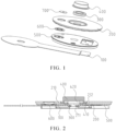
FIG. 1 is an exploded view of a positive cap plate assembly according to some embodiments of the disclosure. -
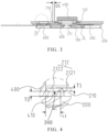
FIG. 2 is a cross-sectional view of the positive cap plate assembly when a positive terminal is not fixed according to some embodiments of the disclosure. -
FIG. 3 is a cross-sectional view of the positive cap plate assembly when the positive terminal is fixed according to some embodiments of the disclosure. -
FIG. 4 is an enlarged view of position A inFIG. 3 . -
FIG. 5 is an enlarged view of position B inFIG. 3 . -
FIG. 6 is a schematic structural diagram of an insulating component according to some embodiments of the disclosure. -
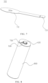
FIG. 7 is a schematic structural diagram of a confluence sheet according to some embodiments of the disclosure. -
FIG. 8 is a schematic structural diagram of a lithium battery according to some embodiments of the disclosure. - 100, confluence sheet; 110, confluence portion; 120, connection portion; 200, top cap sheet; 210, first mounting groove; 211, liquid injection hole; 212, annular protrusion; 2121, vertical portion; 2122, horizontal portion; 220, through hole; 230, groove; 240, limiting groove; 300, elastic gasket; 400, positive terminal; 410, protruding portion; 420, third mounting groove; 500, insulating component; 510, second mounting groove; 520, opening; 600, explosion-proof valve; 700, explosion-proof valve protective film; and 800, housing.
- In related art, in order to inject liquid into the lithium battery during the manufacturing process for the lithium battery, a liquid injection hole is generally provided in a top cap sheet of the lithium battery. Because the liquid injection hole in the top cap sheet of the lithium battery in related art is mostly located at the eccentric position of the top cap sheet, the operator or the equipment needs to position and align the liquid injection hole before injecting liquid into the lithium battery, which increases the difficulty of producing the lithium battery. Moreover, after the lithium battery is filled with liquid, the operator or the equipment needs to weld sealing nails at the liquid injection hole, which increases the production processes of the lithium battery and reduces its production efficiency. Based on the above, embodiments of the disclosure provide a battery module including a lithium battery, as illustrated in
FIG. 1, FIG. 2 ,FIG. 3 , andFIG. 8 , the lithium battery includes ahousing 800, a winding core, a negative cap plate assembly, and a positive cap plate assembly. - Specifically, the
housing 800 is provided with an accommodating space, and the winding core is disposed in the accommodating space. The negative cap plate assembly is disposed on a first side of the winding core, the positive cap plate assembly is disposed on a second side of the winding core, and the first side of the winding core is opposite to the second side. - Furthermore, the positive cap plate assembly includes a
confluence sheet 100, aninsulating component 500, atop cap sheet 200, anelastic gasket 300, and apositive terminal 400. Theconfluence sheet 100 is disposed on the winding core. Theinsulating component 500 is disposed on theconfluence sheet 100. Thetop cap sheet 200 is disposed on theinsulating component 500 and connected to theconfluence sheet 100. Afirst mounting groove 210 is provided in the center of a side of thetop cap sheet 200 away from theconfluence sheet 100. Aliquid injection hole 211 is provided in the center of thefirst mounting groove 210. Theelastic gasket 300 is disposed in thefirst mounting groove 210 and surrounding theliquid injection hole 211. Thepositive terminal 400 is disposed on thefirst mounting groove 210 through a riveting component of thetop cap sheet 200, and thepositive terminal 400 abuts against theelastic gasket 300. - In the lithium battery provided by the embodiments of the disclosure, the first mounting
groove 210 is disposed in the center of thetop cap sheet 200, and theliquid injection hole 211 is disposed in the center of the first mountinggroove 210, so that theliquid injection hole 211 is located at the center of thetop cap sheet 200, and there is no need to position and align theliquid injection hole 211 when injecting liquid into the lithium battery, which can reduce the difficulty of producing the lithium battery. Moreover, because theelastic gasket 300 is disposed surrounding theliquid injection hole 211, and thepositive terminal 400 is disposed in the first mountinggroove 210 and abuts against theelastic gasket 300, thepositive terminal 400 and theelastic gasket 300 can form a sealing structure to seal theliquid injection hole 211, and there is no need to weld sealing nails at theliquid injection hole 211, thereby reducing the production processes of the lithium battery and improving the production efficiency of the lithium battery. In addition, when the lithium battery does not use the sealing nails, the number of components in the positive cap plate assembly can be reduced, which reduces the production cost of the positive cap plate assembly. - Referring to
FIG. 7 , in some embodiments, theconfluence sheet 100 includes aconfluence portion 110 and aconnection portion 120 connected to one side of theconfluence sheet 110, and theconnection portion 120 is connected to thetop cap sheet 200 passing through the insulatingcomponent 500. - In some embodiments, the insulating
component 500 is a silica gel plate. - In some embodiments, the
elastic gasket 300 is a rubber ring or a silica gel ring. - In some embodiments, a bottom of the
positive terminal 400 is provided with athird mounting groove 420 communicated with the first mountinggroove 210. One part of theelastic gasket 300 is disposed in the first mountinggroove 210, and another part of theelastic gasket 300 is disposed in the third mountinggroove 420. - In some embodiments, the first mounting
groove 210 and the third mountinggroove 420 are both circular. - Referring to
FIG. 2 ,FIG. 3, and FIG. 4 , in some embodiments, the riveting component includes anannular protrusion 212 extending from a bottom of the first mountinggroove 210 to a direction away from theconfluence sheet 100. Theannular protrusion 212 is bent towards the center of theliquid injection hole 211, and a limitinggroove 240 is formed between theannular protrusion 212 and the first mountinggroove 210, as illustrated inFIG. 4 . Thepositive terminal 400 includes a protrudingportion 410 extending along a direction from a peripheral wall of thepositive terminal 400 to the limitinggroove 240, and the protrudingportion 410 is inserted into the limitinggroove 240. By setting theannular protrusion 212 being bent towards the center of theliquid injection hole 211, the limitinggroove 240 can be formed between theannular protrusion 212 and the first mountinggroove 210. Moreover, because the protrudingportion 410 is disposed extending along the direction from the peripheral wall of thepositive terminal 400 to the limitinggroove 240, the protrudingportion 410 can be inserted into the limitinggroove 240, ensuring that thepositive terminal 400 can be riveted and fixed on the first mountinggroove 210. - In some embodiments, the entirety of the
annular protrusion 212 extends from the bottom of the first mountinggroove 210 to the direction away from theconfluence sheet 100, and the entirety of the protrudingportion 410 extends along the direction from the peripheral wall of thepositive terminal 400 to the limitinggroove 240. - In some embodiments, the
annular protrusion 212 includes multiple first protrusion portions arranged at intervals, and a first notch is formed between every adjacent two first protrusion portions. Correspondingly, the protrudingportion 410 includes multiple second protrusion portions arranged at intervals, and a second notch is formed between every adjacent two second protrusion portions. The limitinggroove 240 is formed between the first protrusion portions and the first mountinggroove 210, and the first protrusion portions are disposed in the limitinggroove 240. - In some embodiments, the
annular protrusion 212 includes multiple first protrusion portions arranged at intervals, and a first notch is formed between every adjacent two first protrusion portions. The entirety of the protrudingportion 410 extends along the direction from the peripheral wall of thepositive terminal 400 to the limitinggroove 240. The limitinggroove 240 is formed between the first protrusion portions and the first mountinggroove 210, and the protrudingportion 410 is disposed in the limitinggroove 240. - In some embodiments, the entirety of the
annular protrusion 212 extends from the bottom of the first mountinggroove 210 to the direction away from theconfluence sheet 100. The protrudingportion 410 includes multiple second protrusion portions arranged at intervals, and the second notch is formed between every adjacent two second protrusion portions. The limitinggroove 240 is formed between theannular protrusion 212 and the first mountinggroove 210, and the second protrusion portions is disposed in the limitinggroove 240. - Referring to
FIG. 4 , in some embodiments, theannular protrusion 212 includes avertical portion 2121 and ahorizontal portion 2122 connected to thevertical portion 2121. Thevertical portion 2121 is connected to the first mountinggroove 210. A bottom surface of thehorizontal portion 2122 is in close contact with a top surface of the protrudingportion 410, so that the connection between theannular protrusion 212 and the protrudingportion 410 can be sealed, thereby achieving the sealing to theliquid injection hole 211. - In some embodiments, the bottom surface of the
horizontal portion 2122 and the top surface of the protrudingportion 410 are both flat surfaces, so that the bottom surface of thehorizontal portion 2122 can be in better contact with the top surface of the protrudingportion 410. - When the positive cap plate assembly is assembled, the insulating
component 500 is installed on theconfluence sheet 100, theconnection portion 120 of theconfluence sheet 100 passes through anopening 520 of the insulatingcomponent 500, and theconnection portion 120 of theconfluence sheet 100 is installed on a top surface of the insulatingcomponent 500. Then, an explosion-proof valve 600 is installed in asecond mounting groove 510, thetop cap sheet 200 is fixed on theconfluence sheet 100, and thetop cap sheet 200 is connected to theconfluence sheet 100. Then, theelastic gasket 300 and thepositive terminal 400 are placed in the first mountinggroove 210 in sequence, so as to ensure that the protrudingportion 410 of thepositive terminal 400 is disposed in the area where theannular protrusion 212 is located; and at the same time, a force is applied to thepositive terminal 400. Theelastic gasket 300 is pressed by the action of the force applying on thepositive terminal 400, ensuring that a horizontal plane where the protrudingportion 410 is located is lower than a horizontal plane where theannular protrusion 212 is located. Finally, theannular protrusion 212 is bent towards the center of theliquid injection hole 211 to limit the protrudingportion 410, so as to complete the assembly of the lithium battery. - In some embodiments, as illustrated in
FIG. 4 , theannular protrusion 212 has a thickness T1 of 0.5 mm to 1 mm. By selecting theannular protrusion 212 having the thickness T1 of 0.5 mm to 1 mm, ensuring the strength of theannular protrusion 212, and avoiding the deformation of theannular protrusion 212 caused by an excessive low thickness of theannular protrusion 212 when theannular protrusion 212 undergoes greater extrusion force. In some embodiments, theannular protrusion 212 has the thickness T1 of 0.5 mm, 0.8 mm, or 1 mm. - In some embodiments, as illustrated in
FIG. 4 , the protrudingportion 410 has a thickness T2 greater than or equal to 0.5 mm, and has a length L1 greater than or equal to 5 mm. By selecting the protrudingportion 410 having the thickness T2 greater than or equal to 0.5 mm, ensuring the strength of the protrudingportion 410, avoiding the deformation of the protrudingportion 410 caused by an excessive low thickness of the protrudingportion 410 when the protrudingportion 410 undergoes greater extrusion force. Moreover, by selecting the protrudingportion 410 having the length L1 greater than or equal to 5 mm, avoiding reducing the sealing performance of the sealing structure of theliquid injection hole 211 caused by a smaller bonding area between the protrudingportion 410 and thehorizontal portion 2122 due to an excessive short length of the protrudingportion 410. In some embodiments, the protrudingportion 410 has the thickness T2 of 0.5 mm, 0.75 mm, or 0.8 mm, and has the length L1 of 5 mm, 6 mm, or 8 mm. - In some embodiments, as illustrated in
FIG. 3 , a distance D1 between a sidewall of the first mountinggroove 210 and theannular protrusion 212 ranges from 5 mm to 20 mm. In some embodiments, the distance D1 between the sidewall of the first mountinggroove 210 and theannular protrusion 212 is 6 mm, 10 mm, or 18 mm. - In some embodiments, the
positive terminal 400 has a height of 2 mm to 3 mm. In some embodiments, thepositive terminal 400 has the height of 2 mm, 2.5 mm, or 2.8 mm. - In some embodiments, a distance between a top surface of the
positive terminal 400 and a top surface of the third mountinggroove 420 is greater than or equal to 1 mm. In some embodiments, the distance between the top surface of thepositive terminal 400 and the top surface of the third mountinggroove 420 is 2 mm, 3 mm, or 4 mm. - In some embodiments, the third mounting
groove 420 has a depth of 1 mm to 3 mm. - In some embodiments, the
elastic gasket 300 has a compression range of 15% to 45%, ensuing that theelastic gasket 300 can produce sufficient elastic force to press thepositive terminal 400, so that the bottom surface of thehorizontal portion 2122 is in close contact with the top surface of the protrudingportion 410. - Referring to
FIG. 3 ,FIG. 5, and FIG. 6 , in some embodiments, the lithium battery further includes the explosion-proof valve 600, in which the insulatingcomponent 500 is provided with asecond mounting groove 510 at a side of the insulatingcomponent 500 close to thetop cap sheet 200, and the explosion-proof valve 600 is disposed in the second mountinggroove 510. By setting the explosion-proof valve 600, when the internal pressure of the lithium battery is too high, the explosion-proof valve 600 is open and releases the gas inside the lithium battery to reduce the pressure inside the lithium battery, thereby reducing the risk of explosion or leakage of the lithium battery. - In some embodiments, the insulating
component 500 is provided with theopening 520, and theconnection portion 120 of theconfluence sheet 100 is connected to the bottom of thetop cap sheet 200 passing through theopening 520. - Referring to
FIG. 3 ,FIG. 5, and FIG. 6 , in some embodiments, the lithium battery further includes an explosion-proofvalve protection film 700, in which thetop cap sheet 200 is further provided with a through hole 220 disposed corresponding to the second mountinggroove 510, and the explosion-proofvalve protection film 700 is disposed in the through hole 220 away from the explosion-proof valve 600. By setting the explosion-proof valveprotective film 700, it is possible to prevent dust, moisture, or other impurities from entering the explosion-proof valve 600 through the through hole 220, thereby ensuring the smoothness of the explosion-proof valve 600, and avoiding the explosion-proof valve 600 from being affected by external environment and not working normally. - In some embodiments, the
top cap sheet 200 is provided with agroove 230 at a side of thetop cap sheet 200 away from the explosion-proof valve 600. Thegroove 230 is disposed surrounding the through hole 220 and communicated with the through hole 220. The explosion-proof valveprotective film 700 is disposed in thegroove 230. - Because the
positive terminal 400 is disposed in the first mountinggroove 210 by the method of rotary riveting connection, thepositive terminal 400 is in a rotatable state at this case. During the assembly processes of theelastic gasket 300 and thepositive terminal 400, theelastic sealing ring 300 is compressed by thepositive terminal 400, allowing the bottom surface of theelastic gasket 300 to be in close contact with the bottom surface of the first mountinggroove 210, thereby forming a first sealing area to achieve a primary sealing to theliquid injection hole 211. Moreover, when theelastic gasket 300 is compressed by thepositive terminal 400, theelastic gasket 300 has elastic potential energy. Because of the elastic potential energy of theelastic gasket 300, thepositive terminal 400 has a tendency to move away from theelastic gasket 300, so that the top surface of the protrudingportion 410 can be in close contact with the bottom surface of thehorizontal portion 2122 of theannular protrusion 212, forming a second sealing area to carry out a secondary sealing to theliquid injection hole 211.
Claims (15)
- A lithium battery, characterized in that the lithium battery comprises:a housing (800) provided with an accommodating space;a winding core disposed in the accommodating space;a negative cap plate assembly disposed on a first side of the winding core;a positive cap plate assembly disposed on a second side of the winding core, wherein the first side is opposite to the second side; and wherein the positive cap plate assembly comprises:a confluence sheet (100) disposed on the winding core;an insulating component (500) disposed on the confluence sheet (100);a top cap sheet (200) disposed on the insulating component (500) and connected to the confluence sheet (100), wherein a first mounting groove (210) is provided in a center of a side of the top cap sheet (200) away from the confluence sheet (100), and a liquid injection hole (211) is provided in a center of the first mounting groove (210);an elastic gasket (300) disposed in the first mounting groove (210) and surrounding the liquid injection hole (211); anda positive terminal (400) disposed on the first mounting groove (210) through a riveting component of the top cap sheet (200), wherein the positive terminal (400) abuts against the elastic gasket (300).
- The lithium battery according to claim 1, characterized in that the riveting component comprises an annular protrusion (212) extending from a bottom of the first mounting groove (210) to a direction away from the confluence sheet (100), the annular protrusion (212) is bent towards a center of the liquid injection hole (211), and a limiting groove (240) is formed between the annular protrusion (212) and the first mounting groove (210); and the positive terminal (400) comprises a protruding portion (410) extending along a direction from a peripheral wall of the positive terminal (400) to the limiting groove (240), and the protruding portion (410) is inserted into the limiting groove (240).
- The lithium battery according to claim 2, characterized in that the annular protrusion (212) comprises:a vertical portion (2121) connected to the first mounting groove (210); anda horizontal portion (2122) connected to the vertical portion (2121), wherein a bottom surface of the horizontal portion (2122) is in close contact with a top surface of the protruding portion (410).
- The lithium battery according to claim 3, characterized in that the bottom surface of the horizontal portion (2122) and the top surface of the protruding portion (410) are both flat surfaces.
- The lithium battery according to claim 2, characterized in that the annular protrusion (212) has a thickness of 0.5 mm to 1 mm; or
the protruding portion (410) has a thickness greater than or equal to 0.5 mm and has a length greater than or equal to 5 mm. - The lithium battery according to claim 2, characterized in that a distance between a sidewall of the first mounting groove (210) and the annular protrusion (212) ranges from 5 mm to 20 mm.
- The lithium battery according to claim 1, characterized in that the positive terminal (400) has a height of 2 mm to 3 mm.
- The lithium battery according to claim 1, characterized in that the elastic gasket (300) has a compression range of 15% to 45%.
- The lithium battery according to any one of claims 1 to 8, characterized in that the lithium battery further comprises an explosion-proof valve (600), the insulating component (500) is provided with a second mounting groove (510) at a side of the insulating component (500) close to the top cap sheet (200), and the explosion-proof valve (600) is disposed in the second mounting groove (510).
- The lithium battery according to claim 9, characterized in that the lithium battery further comprises an explosion-proof valve protective film (700), the top cap sheet (200) is provided with a through hole (220) disposed corresponding to the second mounting groove (510), and the explosion-proof valve protective film (700) is disposed in the through hole (220) away from the explosion-proof valve (600).
- The lithium battery according to claim 10, characterized in that the top cap sheet (200) is provided with a groove (230) at a side of the top cap sheet (200) away from the explosion-proof valve (600), the groove (230) is disposed surrounding and communicated with the through hole (220), and the explosion-proof valve protective film (700) is disposed in the groove (230).
- The lithium battery according to claim 1, characterized in that the confluence sheet (100) comprises a confluence portion (110) and a connection portion (120) disposed at a side of the confluence portion (110), wherein the connection portion (120) is connected to the top cap sheet (200) passing through the insulating component (500).
- The lithium battery according to claim 12, characterized in that the insulating component (500) is provided with an opening (520), and the connection portion (120) is connected to a bottom of the top cap sheet (200) passing through the opening (520).
- The lithium battery according to claim 1, characterized in that a bottom of the positive terminal (400) is provided with a third mounting groove (420) communicated with the first mounting groove (210), a part of the elastic gasket (300) is disposed in the first mounting groove (210), and another part of the elastic gasket (300) is disposed in the third mounting groove (420).
- A battery module comprising the lithium battery as claimed in any one of claims 1 to 14.
Priority Applications (1)
| Application Number | Priority Date | Filing Date | Title |
|---|---|---|---|
| MA71336A MA71336A (en) | 2023-10-31 | 2024-09-20 | LITHIUM BATTERY |
Applications Claiming Priority (2)
| Application Number | Priority Date | Filing Date | Title |
|---|---|---|---|
| CN202322944694.1U CN221080304U (en) | 2023-10-31 | 2023-10-31 | A lithium battery |
| PCT/CN2023/140212 WO2025091663A1 (en) | 2023-10-31 | 2023-12-20 | Lithium battery |
Publications (1)
| Publication Number | Publication Date |
|---|---|
| EP4550503A1 true EP4550503A1 (en) | 2025-05-07 |
Family
ID=92894883
Family Applications (1)
| Application Number | Title | Priority Date | Filing Date |
|---|---|---|---|
| EP24201668.1A Pending EP4550503A1 (en) | 2023-10-31 | 2024-09-20 | Lithium battery |
Country Status (5)
| Country | Link |
|---|---|
| US (1) | US20250141066A1 (en) |
| EP (1) | EP4550503A1 (en) |
| KR (1) | KR20250063156A (en) |
| DE (1) | DE202024106180U1 (en) |
| MA (1) | MA71336A (en) |
Citations (2)
| Publication number | Priority date | Publication date | Assignee | Title |
|---|---|---|---|---|
| US20230055727A1 (en) * | 2021-08-17 | 2023-02-23 | Xiamen Hithium New Energy Technology Co., Ltd. | Top cover assembly of cell, cell, and power battery |
| US20230344097A1 (en) * | 2021-08-23 | 2023-10-26 | Contemporary Amperex Technology Co., Limited | Battery cell, battery, and electric apparatus |
-
2024
- 2024-08-05 KR KR1020240104152A patent/KR20250063156A/en active Pending
- 2024-09-20 MA MA71336A patent/MA71336A/en unknown
- 2024-09-20 EP EP24201668.1A patent/EP4550503A1/en active Pending
- 2024-10-23 US US18/923,757 patent/US20250141066A1/en active Pending
- 2024-10-28 DE DE202024106180.2U patent/DE202024106180U1/en active Active
Patent Citations (2)
| Publication number | Priority date | Publication date | Assignee | Title |
|---|---|---|---|---|
| US20230055727A1 (en) * | 2021-08-17 | 2023-02-23 | Xiamen Hithium New Energy Technology Co., Ltd. | Top cover assembly of cell, cell, and power battery |
| US20230344097A1 (en) * | 2021-08-23 | 2023-10-26 | Contemporary Amperex Technology Co., Limited | Battery cell, battery, and electric apparatus |
Also Published As
| Publication number | Publication date |
|---|---|
| MA71336A (en) | 2025-04-30 |
| DE202024106180U1 (en) | 2024-11-12 |
| KR20250063156A (en) | 2025-05-08 |
| US20250141066A1 (en) | 2025-05-01 |
Similar Documents
| Publication | Publication Date | Title |
|---|---|---|
| EP1705732B1 (en) | Lithium secondary battery | |
| KR100599754B1 (en) | Cap assembly of secondary battery and secondary battery and terminal assembly method of cap assembly | |
| US8822050B2 (en) | Electric storage apparatus | |
| US20220021067A1 (en) | Battery module, battery pack and vehicle | |
| KR20000019349A (en) | Cap assembly of secondary cell | |
| US20250158178A1 (en) | Battery, battery module, and electric device | |
| KR101073313B1 (en) | Secondary battery | |
| KR101117622B1 (en) | Rechargeable battery | |
| CN113131054A (en) | Power battery utmost point post packaging structure, top cap, power battery | |
| US12057590B1 (en) | End cover assembly, energy storage apparatus, and electricity-consumption device | |
| EP4550503A1 (en) | Lithium battery | |
| KR20160015778A (en) | A sylnder type battery having enhanced vibration resistant property | |
| CN117317476B (en) | Secondary battery and cover assembly thereof | |
| CN221080181U (en) | Secondary batteries, battery packs and electronic devices | |
| CN219066985U (en) | Cylindrical lithium ion battery | |
| CN217405562U (en) | Battery upper cover and battery | |
| KR20040022715A (en) | Lithium secondary battery | |
| CN117497975A (en) | End cover components, energy storage devices, electrical equipment and liquid injection methods | |
| KR100274939B1 (en) | A device for sealing the electrode terminals of lithium batterys | |
| WO2025091663A1 (en) | Lithium battery | |
| CN223502014U (en) | Cell cover and cell | |
| CN223462310U (en) | Battery sealing device and secondary battery comprising same | |
| CN221530022U (en) | Secondary batteries and battery packs | |
| CN223843014U (en) | Secondary batteries, battery packs and electronic devices | |
| CN222995594U (en) | Sealing assembly of cylindrical battery and cylindrical battery |
Legal Events
| Date | Code | Title | Description |
|---|---|---|---|
| PUAI | Public reference made under article 153(3) epc to a published international application that has entered the european phase |
Free format text: ORIGINAL CODE: 0009012 |
|
| STAA | Information on the status of an ep patent application or granted ep patent |
Free format text: STATUS: REQUEST FOR EXAMINATION WAS MADE |
|
| 17P | Request for examination filed |
Effective date: 20240920 |
|
| AK | Designated contracting states |
Kind code of ref document: A1 Designated state(s): AL AT BE BG CH CY CZ DE DK EE ES FI FR GB GR HR HU IE IS IT LI LT LU LV MC ME MK MT NL NO PL PT RO RS SE SI SK SM TR |