EP4550501A2 - Lug alignment apparatus and method - Google Patents
Lug alignment apparatus and method Download PDFInfo
- Publication number
- EP4550501A2 EP4550501A2 EP24209722.8A EP24209722A EP4550501A2 EP 4550501 A2 EP4550501 A2 EP 4550501A2 EP 24209722 A EP24209722 A EP 24209722A EP 4550501 A2 EP4550501 A2 EP 4550501A2
- Authority
- EP
- European Patent Office
- Prior art keywords
- jig box
- frame
- moveable
- lugs
- feet
- Prior art date
- Legal status (The legal status is an assumption and is not a legal conclusion. Google has not performed a legal analysis and makes no representation as to the accuracy of the status listed.)
- Pending
Links
Images


Classifications
-
- H—ELECTRICITY
- H01—ELECTRIC ELEMENTS
- H01M—PROCESSES OR MEANS, e.g. BATTERIES, FOR THE DIRECT CONVERSION OF CHEMICAL ENERGY INTO ELECTRICAL ENERGY
- H01M50/00—Constructional details or processes of manufacture of the non-active parts of electrochemical cells other than fuel cells, e.g. hybrid cells
- H01M50/50—Current conducting connections for cells or batteries
- H01M50/531—Electrode connections inside a battery casing
- H01M50/54—Connection of several leads or tabs of plate-like electrode stacks, e.g. electrode pole straps or bridges
-
- H—ELECTRICITY
- H01—ELECTRIC ELEMENTS
- H01M—PROCESSES OR MEANS, e.g. BATTERIES, FOR THE DIRECT CONVERSION OF CHEMICAL ENERGY INTO ELECTRICAL ENERGY
- H01M10/00—Secondary cells; Manufacture thereof
- H01M10/04—Construction or manufacture in general
- H01M10/0404—Machines for assembling batteries
-
- B—PERFORMING OPERATIONS; TRANSPORTING
- B22—CASTING; POWDER METALLURGY
- B22D—CASTING OF METALS; CASTING OF OTHER SUBSTANCES BY THE SAME PROCESSES OR DEVICES
- B22D19/00—Casting in, on, or around objects which form part of the product
- B22D19/04—Casting in, on, or around objects which form part of the product for joining parts
-
- H—ELECTRICITY
- H01—ELECTRIC ELEMENTS
- H01M—PROCESSES OR MEANS, e.g. BATTERIES, FOR THE DIRECT CONVERSION OF CHEMICAL ENERGY INTO ELECTRICAL ENERGY
- H01M10/00—Secondary cells; Manufacture thereof
- H01M10/05—Accumulators with non-aqueous electrolyte
- H01M10/058—Construction or manufacture
- H01M10/0585—Construction or manufacture of accumulators having only flat construction elements, i.e. flat positive electrodes, flat negative electrodes and flat separators
-
- H—ELECTRICITY
- H01—ELECTRIC ELEMENTS
- H01M—PROCESSES OR MEANS, e.g. BATTERIES, FOR THE DIRECT CONVERSION OF CHEMICAL ENERGY INTO ELECTRICAL ENERGY
- H01M10/00—Secondary cells; Manufacture thereof
- H01M10/06—Lead-acid accumulators
- H01M10/12—Construction or manufacture
- H01M10/14—Assembling a group of electrodes or separators
-
- H—ELECTRICITY
- H01—ELECTRIC ELEMENTS
- H01M—PROCESSES OR MEANS, e.g. BATTERIES, FOR THE DIRECT CONVERSION OF CHEMICAL ENERGY INTO ELECTRICAL ENERGY
- H01M50/00—Constructional details or processes of manufacture of the non-active parts of electrochemical cells other than fuel cells, e.g. hybrid cells
- H01M50/50—Current conducting connections for cells or batteries
- H01M50/502—Interconnectors for connecting terminals of adjacent batteries; Interconnectors for connecting cells outside a battery casing
- H01M50/514—Methods for interconnecting adjacent batteries or cells
-
- H—ELECTRICITY
- H01—ELECTRIC ELEMENTS
- H01M—PROCESSES OR MEANS, e.g. BATTERIES, FOR THE DIRECT CONVERSION OF CHEMICAL ENERGY INTO ELECTRICAL ENERGY
- H01M50/00—Constructional details or processes of manufacture of the non-active parts of electrochemical cells other than fuel cells, e.g. hybrid cells
- H01M50/50—Current conducting connections for cells or batteries
- H01M50/531—Electrode connections inside a battery casing
- H01M50/54—Connection of several leads or tabs of plate-like electrode stacks, e.g. electrode pole straps or bridges
- H01M50/541—Connection of several leads or tabs of plate-like electrode stacks, e.g. electrode pole straps or bridges for lead-acid accumulators
Definitions
- This invention relates to an apparatus for aligning the lugs on battery plates for use in a process for manufacturing electrical batteries.
- alternating positive and negative plates are connected to each other by lugs projecting from edges of the plates.
- the connection is produced by clamping a series of plates in a jig box with the lugs aligned, and inverting the jig box over a mould which is filled with molten lead and the lugs are dipped into the filled mould and the lead allowed to solidify and provide the electrical connection between the plates.
- the lugs are not fully aligned. If this occurs, they may not fit into the mould properly. This can cause damage to the lugs or require that the manufacturing process be halted to remove the badly aligned plates.
- This invention aims to provide an apparatus that can improve accuracy of alignment of the lugs.
- a first aspect of this invention comprises apparatus for aligning the lugs on a stack of battery plates in a jig box, comprising a frame carrying a lug alignment mechanism for positioning over the jig box, wherein the frame comprises: a set of feet that engage on opposite first and second sides of the jig box to locate the lug alignment mechanism in a predetermined position relative to the jig box; wherein the frame feet on one side comprise fixed surfaces configured to engage contact surfaces on a corresponding first side of the jig box; the frame feet on the opposite side comprise actuators with moveable surfaces for engaging contact surfaces on the corresponding second side of the jig box; and the actuators are operable such that when the frame is positioned over the jig box with the frame feet adjacent to the contact surfaces, the moveable surfaces are moveable between a first position in which the moveable surfaces are spaced from the contact surfaces on the second side of the jig box, and a second position in which the moveable surfaces are engaged with the contact surfaces on the second side
- Positioning the actuator to the first position increases the space between the fixed and moveable surfaces, reducing the likelihood of contact between these surfaces and the jig box when the frame is being lowered onto the jig box, thus reducing wear. Positioning the actuator to the second position avoids any residual clearance between the surfaces, leading to more accurate positioning.
- the actuators can be configured to urge the moveable surface against the contact surface on the second side of the jig box and draw the fixed feet into engagement with the contact surface on the first side of the jig box. This is less likely to cause wear than sliding feet with a fixed spacing over the jig box.
- the alignment mechanism can comprise actuators mounted on the frame and configured to act on opposite edges of the lugs to urge the lugs into alignment.
- the frame feet can also comprise stop surfaces which are engageable with upper edges of the sides of the jig box to determine the position of the alignment mechanism above the jig box.
- a second aspect of this invention comprises a method of aligning the lugs on a stack of battery plates in a jig box using the apparatus, comprising positioning the apparatus above the jig box; operating the frame feet actuators such that the moveable surfaces are in the first position; lowering the apparatus until the frame feet are adjacent to the contact surfaces on the jig box; operating the frame feet actuators such that the moveable surfaces are in the second position and the moveable surfaces are engaged with the contact surfaces on the second side of the jig box and the fixed surfaces are engaged with the contact surfaces on the first side of the jig box; and operating the alignment mechanism to align the lugs on the battery plates in the jig box.
- FIG. 1 shows a stack of battery plates used in the production of lead-acid batteries.
- the stack 10 comprises alternating positive plates 12 1 ... 12 10 and negative plates 13 1 ... 13 10 separated by a porous separating material (not shown) for holding electrolyte. While ten square plates are shown here, the stack can comprise plates of any appropriate shape and number
- Each plate 12 1 ... 12 10 ,13 1 ... 13 10 has a respective lug 14 1 ... 14 10 ,15 1 ... 15 10 to allow the plates of the same type to be connected to each other.
- Each stack of plates corresponds to a cell in the battery.
- stacks of plates are clamped in a jog box which holds the stacks in the configuration of the final battery and conducting straps are cast onto the lugs 14, 15.
- Figure 2 shows a system for casing the straps onto the lugs 14, 15.
- the stacks of plates are clamped in a jig box 20.
- the jig box 20 can be rotated about a horizontal axis 22 so that the stacks of plated can be inverted, as shown in Figure 2 , with the lugs 14, 15 pointing downwards.
- the jog box 20 is supported by a support frame 24 which allows the lugs 14, 15 to be inserted into a mould 26 for casting the straps onto the lugs.
- the cavities (not shown) in the mould 26 have to be wide enough to accommodate the lugs 14, 15, including any misalignment or variation in alignment relative to the axis 22.
- the mould cavitied have to be oversized. This in turn means that the amount of lead cast onto the lugs is more than is strictly necessary to provide an appropriate electrical connection.
- Prior moulds are typically large enough to accommodate a 0.5 mm misalignment in the lugs 14, 15 due to the errors in the previous alignment systems. Over the life of a mould, this can lead to a significant waste of lead.
- Figure 3 shows an end view of an alignment apparatus according to one embodiment of the invention positioned on a jig box 20.
- the jig box is rotated 180 degrees about the axis 22 compared to the position shown in Figure 1 .
- stacks of plates are loaded into the jig box 20 from above.
- the jig box 20 holds the stacks in the configuration to be used in the completed battery. Initially, the plates can be moved laterally with respect to each other.
- the lugs 14, 15 project from the top of the jig box 20.
- the alignment apparatus comprises a frame 30 that has a lug alignment mechanism in the form of actuators 32, 34 that are operable to act on the edges of the lugs 14, 15 to push them into alignment with each other, and into position relative to the jig box.
- the frame 30 is positioned on the jig box 20 by means of sets of feet 36, 38 (only one of each set is shown) which sit on opposite sides of the jig box 20.
- a first foot 36 comprises a fixed vertical surface 40 and a horizontal stop surface 42 that are configured to engage a contact surface 44 on the facing side of the jig box 20.
- the contact surface 44 is formed of a hardened insert that extends to the upper edge of the jig box 20.
- a second foot comprises an actuator 46 having a moveable vertical surface 48 and a horizontal stop surface 50 configured to engage a contact surface 52 on the facing side of the jig box 20.
- the contact surface 52 is formed of a hardened insert that extends to the upper edge of the jig box 20.
- the frame 30 is lowered over the jig box 20 until the stop surfaces 42, 50 engage the upper edges of the jig box 20.
- the fixed surface 40 and moveable surface 48 are in a first configuration shown in Figure 4 , with the actuator 46 in a retracted position. With the actuator in the retracted position, there is a relatively large space between the fixed surface 40 and the moveable surface 48 so the feet 36, 38 cab be seated onto the edges of the jig box without the likelihood of contact between the fixed and movable surfaces 40, 48 and the respective contact surfaces 44, 52.
- the actuator 46 can be operated to move the second configuration in which the moveable surface is urged against the contact surface 52 which has the effect of drawing the fixed surface 40 into contact with the contact surface 44. This provides lateral location of the frame 30 on the jig box 20.
- the alignment mechanism can then be operated to align the lugs 14, 15.
- the use of the actuator means that horizontal clearance is taken up before the lugs are aligned, providing a relatively accurate lateral position of the frame 30 relative to the jig box. This in turn reduced the lateral uncertainly of the position of the lugs after alignment.
- the plates are securely clamped in position in the jig box 20.
- the actuator 46 is then returned to the first configuration ( Figure 4 ) and the frame 30 can be lifted off the jig box 20 so that the jig box can be inverted for positioning over the mould ( Figure 2 ).
- FIG 6 shows a comparative embodiment in which both feet 56, 58 comprise fixed surfaces 60, 62.
- both feet 56, 58 comprise fixed surfaces 60, 62.
- This clearance needs to be big enough to avoid jamming by interference yet small enough to allow alignment of the lugs once the frame is in pace. Because this clearance is relatively small, the feet will often contact the contact surfaces when the frame is being positioned on the jig box. This leads to wear of the fixed surfaces and increased uncertainty in lateral position.
- the width of the mould cavities can be smaller without risking the lugs contacting the sides of the mould cavities as they are inserted.
- actuator can be selected according to requirements, as can the particular configuration of fixed, moveable, and contact surfaces.
Landscapes
- Chemical & Material Sciences (AREA)
- Chemical Kinetics & Catalysis (AREA)
- Electrochemistry (AREA)
- General Chemical & Material Sciences (AREA)
- Engineering & Computer Science (AREA)
- Manufacturing & Machinery (AREA)
- Mechanical Engineering (AREA)
- Secondary Cells (AREA)
- Battery Mounting, Suspending (AREA)
Abstract
Description
- This invention relates to an apparatus for aligning the lugs on battery plates for use in a process for manufacturing electrical batteries.
- In the production of batteries, alternating positive and negative plates are connected to each other by lugs projecting from edges of the plates. The connection is produced by clamping a series of plates in a jig box with the lugs aligned, and inverting the jig box over a mould which is filled with molten lead and the lugs are dipped into the filled mould and the lead allowed to solidify and provide the electrical connection between the plates.
- When the plates are loaded into the jig box, it is possible that the lugs are not fully aligned. If this occurs, they may not fit into the mould properly. This can cause damage to the lugs or require that the manufacturing process be halted to remove the badly aligned plates.
- In an attempt to reduce this problem, it has been proposed to use an alignment mechanism to force the lugs into alignment. The plates are loaded into the jig box with the lugs pointing upwards and nominally aligned. A frame is lowered onto the jig box and located by means of feet which engage against hardened plates on the sides of the jig box. Once the frame is in place, actuators mounted on the fame act on the lugs to move the plates so that the lugs are more accurately aligned.
- There must be sufficient clearance to allow the feet to be place onto and removed from the jig box without jamming. Also, repeated contact between the feet and the sides of the jig box can lead to wear of the feet. These factors mean that there is always a degree of play in the system which in turn leads to less accurate alignment of the lugs. The potential for inaccurate alignment of the lugs has to be accommodated in the design of the mould.
- This invention aims to provide an apparatus that can improve accuracy of alignment of the lugs.
- A first aspect of this invention comprises apparatus for aligning the lugs on a stack of battery plates in a jig box, comprising a frame carrying a lug alignment mechanism for positioning over the jig box, wherein the frame comprises: a set of feet that engage on opposite first and second sides of the jig box to locate the lug alignment mechanism in a predetermined position relative to the jig box; wherein the frame feet on one side comprise fixed surfaces configured to engage contact surfaces on a corresponding first side of the jig box; the frame feet on the opposite side comprise actuators with moveable surfaces for engaging contact surfaces on the corresponding second side of the jig box; and the actuators are operable such that when the frame is positioned over the jig box with the frame feet adjacent to the contact surfaces, the moveable surfaces are moveable between a first position in which the moveable surfaces are spaced from the contact surfaces on the second side of the jig box, and a second position in which the moveable surfaces are engaged with the contact surfaces on the second side of the jig box and the fixed surfaces are engaged with the contact surfaces on the first side of the jig box; and the alignment mechanism is operable to align the lugs when the fixed and moveable surfaces on the frame feet are engaged with the contact surfaces on the jig box.
- Positioning the actuator to the first position increases the space between the fixed and moveable surfaces, reducing the likelihood of contact between these surfaces and the jig box when the frame is being lowered onto the jig box, thus reducing wear. Positioning the actuator to the second position avoids any residual clearance between the surfaces, leading to more accurate positioning.
- The actuators can be configured to urge the moveable surface against the contact surface on the second side of the jig box and draw the fixed feet into engagement with the contact surface on the first side of the jig box. This is less likely to cause wear than sliding feet with a fixed spacing over the jig box.
- The alignment mechanism can comprise actuators mounted on the frame and configured to act on opposite edges of the lugs to urge the lugs into alignment.
- The frame feet can also comprise stop surfaces which are engageable with upper edges of the sides of the jig box to determine the position of the alignment mechanism above the jig box.
- A second aspect of this invention comprises a method of aligning the lugs on a stack of battery plates in a jig box using the apparatus, comprising positioning the apparatus above the jig box; operating the frame feet actuators such that the moveable surfaces are in the first position; lowering the apparatus until the frame feet are adjacent to the contact surfaces on the jig box; operating the frame feet actuators such that the moveable surfaces are in the second position and the moveable surfaces are engaged with the contact surfaces on the second side of the jig box and the fixed surfaces are engaged with the contact surfaces on the first side of the jig box; and operating the alignment mechanism to align the lugs on the battery plates in the jig box.
- Various aspects and embodiments of the invention are disclosed below.
-
-
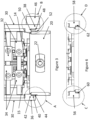
Figure 1 shows a stack of battery plates. -
Figure 2 shows an end view of jig box and a strap mould. -
Figure 3 shows an end view of an alignment apparatus mounted on a jig box. -
Figure 4 shows detail of areas A and B ofFigure 3 in a first configuration. -
Figure 5 shows detail of areas A and B ofFigure 3 in a second configuration. -
Figure 6 shows a partial end view of a known alignment apparatus. -
Figure 7 detail of areas C and D ofFigure 6 . -
Figure 1 shows a stack of battery plates used in the production of lead-acid batteries. Thestack 10 comprises alternating positive plates 121 ... 1210 and negative plates 131 ... 1310 separated by a porous separating material (not shown) for holding electrolyte. While ten square plates are shown here, the stack can comprise plates of any appropriate shape and number Each plate 121 ... 1210,131... 1310 has arespective lug 141 ... 1410,151... 1510 to allow the plates of the same type to be connected to each other. - Each stack of plates corresponds to a cell in the battery. To form the battery, stacks of plates are clamped in a jog box which holds the stacks in the configuration of the final battery and conducting straps are cast onto the
lugs Figure 2 shows a system for casing the straps onto thelugs jig box 20. Thejig box 20 can be rotated about ahorizontal axis 22 so that the stacks of plated can be inverted, as shown inFigure 2 , with thelugs jog box 20 is supported by asupport frame 24 which allows thelugs mould 26 for casting the straps onto the lugs. The cavities (not shown) in themould 26 have to be wide enough to accommodate thelugs axis 22. In essence, the mould cavitied have to be oversized. This in turn means that the amount of lead cast onto the lugs is more than is strictly necessary to provide an appropriate electrical connection. Prior moulds are typically large enough to accommodate a 0.5 mm misalignment in thelugs -
Figure 3 shows an end view of an alignment apparatus according to one embodiment of the invention positioned on ajig box 20. In this case, the jig box is rotated 180 degrees about theaxis 22 compared to the position shown inFigure 1 . In use, stacks of plates are loaded into thejig box 20 from above. Thejig box 20 holds the stacks in the configuration to be used in the completed battery. Initially, the plates can be moved laterally with respect to each other. Thelugs jig box 20. The alignment apparatus comprises aframe 30 that has a lug alignment mechanism in the form ofactuators lugs - The
frame 30 is positioned on thejig box 20 by means of sets offeet 36, 38 (only one of each set is shown) which sit on opposite sides of thejig box 20. - A
first foot 36 comprises a fixedvertical surface 40 and ahorizontal stop surface 42 that are configured to engage acontact surface 44 on the facing side of thejig box 20. Thecontact surface 44 is formed of a hardened insert that extends to the upper edge of thejig box 20. - A second foot comprises an
actuator 46 having a moveablevertical surface 48 and ahorizontal stop surface 50 configured to engage acontact surface 52 on the facing side of thejig box 20. As with thecontact surface 44, thecontact surface 52 is formed of a hardened insert that extends to the upper edge of thejig box 20. - In use, the
frame 30 is lowered over thejig box 20 until thestop surfaces jig box 20. This defines the vertical position of the alignment mechanism with respect to thejig box 20. Thefixed surface 40 andmoveable surface 48 are in a first configuration shown inFigure 4 , with theactuator 46 in a retracted position. With the actuator in the retracted position, there is a relatively large space between the fixedsurface 40 and themoveable surface 48 so thefeet movable surfaces jig box 20, there is a relativelysmall clearance 49 between the fixedsurface 40 and thecontact surface 44, and a relatively larger space between themoveable surface 48 and thecontact surface 52. - Once the
frame 30 is seated on thejig box 20, theactuator 46 can be operated to move the second configuration in which the moveable surface is urged against thecontact surface 52 which has the effect of drawing the fixedsurface 40 into contact with thecontact surface 44. This provides lateral location of theframe 30 on thejig box 20. The alignment mechanism can then be operated to align thelugs - The use of the actuator means that horizontal clearance is taken up before the lugs are aligned, providing a relatively accurate lateral position of the
frame 30 relative to the jig box. This in turn reduced the lateral uncertainly of the position of the lugs after alignment. - Once the
lugs jig box 20. Theactuator 46 is then returned to the first configuration (Figure 4 ) and theframe 30 can be lifted off thejig box 20 so that the jig box can be inverted for positioning over the mould (Figure 2 ). -
Figure 6 shows a comparative embodiment in which bothfeet surfaces residual clearance Figure 7 ). This clearance needs to be big enough to avoid jamming by interference yet small enough to allow alignment of the lugs once the frame is in pace. Because this clearance is relatively small, the feet will often contact the contact surfaces when the frame is being positioned on the jig box. This leads to wear of the fixed surfaces and increased uncertainty in lateral position. - Because the lateral alignment of the lugs with respect to the jig box can be more accurately controlled by use of the actuator, the width of the mould cavities can be smaller without risking the lugs contacting the sides of the mould cavities as they are inserted.
- Further changes can be made within the scope of the invention. For example, the exact form of actuator can be selected according to requirements, as can the particular configuration of fixed, moveable, and contact surfaces.
Claims (5)
- Apparatus for aligning the lugs on a stack of battery plates in a jig box, comprising:a frame carrying a lug alignment mechanism for positioning over the jig box,wherein the frame comprises:a set of feet that engage on opposite first and second sides of the jig box to locate the lug alignment mechanism in a predetermined position relative to the jig box,wherein:the frame feet on one side comprise fixed surfaces configured to engage contact surfaces on a corresponding first side of the jig box,the frame feet on the opposite side comprise actuators with moveable surfaces for engaging contact surfaces on the corresponding second side of the jig box, andthe actuators are operable such that when the frame is positioned over the jig box with the frame feet adjacent to the contact surfaces, the moveable surfaces are moveable between a first position in which the moveable surfaces are spaced from the contact surfaces on the second side of the jig box, and a second position in which the moveable surfaces are engaged with the contact surfaces on the second side of the jig box and the fixed surfaces are engaged with the contact surfaces on the first side of the jig box; andthe alignment mechanism is operable to align the lugs when the fixed andmoveable surfaces on the frame feet are engaged with the contact surfaces on the jig box.
- Apparatus as claimed in claim 1, wherein the actuators are configured to urge the moveable surface against the contact surface on the second side of the jig box and draw the fixed feet into engagement with the contact surface on the first side of the jig box.
- Apparatus as claimed in claim 1 or 2, wherein the alignment mechanism comprises actuators mounted on the frame and configured to act on opposite edges of the lugs to urge the lugs into alignment.
- Apparatus as claimed in any preceding claim, wherein the frame feet comprise stop surfaces which are engageable with upper edges of the sides of the jig box to determine the position of the alignment mechanism above the jig box.
- A method of aligning the lugs on a stack of battery plates in a jig box using the apparatus of any preceding claim, comprising:positioning the apparatus above the jig box;operating the frame feet actuators such that the moveable surfaces are in the first position;lowering the apparatus until the frame feet are adjacent to the contact surfaces on the jig box;operating the frame feet actuators such that the moveable surfaces are in the second position and the moveable surfaces are engaged with the contact surfaces on the second side of the jig box and the fixed surfaces are engaged with the contact surfaces on the first side of the jig box; andoperating the alignment mechanism to align the lugs on the battery plates in the jig box.
Applications Claiming Priority (1)
| Application Number | Priority Date | Filing Date | Title |
|---|---|---|---|
| GB2316573.1A GB2635141B (en) | 2023-10-30 | 2023-10-30 | Lug alignment apparatus and method |
Publications (2)
| Publication Number | Publication Date |
|---|---|
| EP4550501A2 true EP4550501A2 (en) | 2025-05-07 |
| EP4550501A3 EP4550501A3 (en) | 2025-07-09 |
Family
ID=89073729
Family Applications (1)
| Application Number | Title | Priority Date | Filing Date |
|---|---|---|---|
| EP24209722.8A Pending EP4550501A3 (en) | 2023-10-30 | 2024-10-30 | Lug alignment apparatus and method |
Country Status (3)
| Country | Link |
|---|---|
| US (1) | US20250140888A1 (en) |
| EP (1) | EP4550501A3 (en) |
| GB (1) | GB2635141B (en) |
Family Cites Families (4)
| Publication number | Priority date | Publication date | Assignee | Title |
|---|---|---|---|---|
| US4349959A (en) * | 1980-04-14 | 1982-09-21 | General Battery Corporation | Apparatus for aligning battery plates and separators |
| US4824307A (en) * | 1988-02-11 | 1989-04-25 | Tekmax Inc. | Apparatus for vertically stacking battery plates |
| CN101061598B (en) * | 2004-11-22 | 2010-06-09 | Bm-电池机械有限公司 | Method and apparatus for connecting battery panels into stacks and inserting the stacks into battery boxes |
| CN211088385U (en) * | 2019-12-16 | 2020-07-24 | 安徽省华森电源有限公司 | Pole plate lug aligning device for welding lead storage battery pole group |
-
2023
- 2023-10-30 GB GB2316573.1A patent/GB2635141B/en active Active
-
2024
- 2024-10-30 EP EP24209722.8A patent/EP4550501A3/en active Pending
- 2024-10-30 US US18/931,302 patent/US20250140888A1/en active Pending
Also Published As
| Publication number | Publication date |
|---|---|
| GB202316573D0 (en) | 2023-12-13 |
| EP4550501A3 (en) | 2025-07-09 |
| GB2635141B (en) | 2026-02-11 |
| US20250140888A1 (en) | 2025-05-01 |
| GB2635141A (en) | 2025-05-07 |
Similar Documents
| Publication | Publication Date | Title |
|---|---|---|
| US20210057775A1 (en) | Stack holding apparatus | |
| CN106129448A (en) | A kind of Full-automatic battery cell enters housing apparatus | |
| JP2010510681A (en) | Method of forming a stack of wafers to be doped on one side, particularly a solar wafer, and a handling system for loading a plurality of wafer batches on a process boat | |
| CN109396835B (en) | Automatic kludge of high accuracy padlock | |
| KR102358127B1 (en) | secondary battery cell transfer carrier fixing apparatus | |
| CN107931576B (en) | Full-automatic lead storage battery cast welding device | |
| EP4550501A2 (en) | Lug alignment apparatus and method | |
| US20060113808A1 (en) | Handling apparatus for passing electronic components, in particular ICs, to a testing apparatus | |
| KR102885201B1 (en) | Align apparatus and method for battery cell | |
| CN112756588A (en) | Efficient lead-acid storage battery cast-weld production process | |
| CN108448150A (en) | stacking device | |
| KR102358131B1 (en) | secondary battery cell transfer carrier alignment apparatus | |
| EP3336950A1 (en) | A method for connecting a group of electrode plates of a lead-acid battery, a method for manufacturing a lead-acid battery, a lead-acid battery manufactured by the method, and a device for connecting a group of electrode plates of a lead-acid battery | |
| EP0958631B1 (en) | Frame and loading apparatus for groups of battery plates | |
| EP4299205A1 (en) | Notching apparatus for electrode substrate of rechargeable battery | |
| CN116154233B (en) | Fuel cell automatic detection device and control method thereof | |
| CN217983455U (en) | Square cell into the shell tooling | |
| CN110220385B (en) | Bare cell contact type preheating furnace for lithium battery | |
| CN213645444U (en) | Bending equipment with multiple bending fillets | |
| KR20200069883A (en) | Apparatus for stacking of system for producing electrodes of battery and method for stacking producing electrodes of battery | |
| CN220106605U (en) | Stack assist device and stack apparatus for fuel cell | |
| CN222514923U (en) | Battery cell stacking pitch changing mechanism and battery cell stacking equipment | |
| EP1006626A2 (en) | A wire laying apparatus, a wire laying method, a wire laying mold, a wire straightening mechanism and a back-up assembly of a press insulation-displacing mechanism | |
| CN114446835B (en) | Semiconductor process equipment and its separation devices | |
| CN216648395U (en) | Soft-packaged electrical core tool |
Legal Events
| Date | Code | Title | Description |
|---|---|---|---|
| PUAI | Public reference made under article 153(3) epc to a published international application that has entered the european phase |
Free format text: ORIGINAL CODE: 0009012 |
|
| STAA | Information on the status of an ep patent application or granted ep patent |
Free format text: STATUS: THE APPLICATION HAS BEEN PUBLISHED |
|
| AK | Designated contracting states |
Kind code of ref document: A2 Designated state(s): AL AT BE BG CH CY CZ DE DK EE ES FI FR GB GR HR HU IE IS IT LI LT LU LV MC ME MK MT NL NO PL PT RO RS SE SI SK SM TR |
|
| PUAL | Search report despatched |
Free format text: ORIGINAL CODE: 0009013 |
|
| AK | Designated contracting states |
Kind code of ref document: A3 Designated state(s): AL AT BE BG CH CY CZ DE DK EE ES FI FR GB GR HR HU IE IS IT LI LT LU LV MC ME MK MT NL NO PL PT RO RS SE SI SK SM TR |
|
| RIC1 | Information provided on ipc code assigned before grant |
Ipc: H01M 10/14 20060101ALI20250604BHEP Ipc: H01M 50/541 20210101ALI20250604BHEP Ipc: H01M 50/514 20210101ALI20250604BHEP Ipc: H01M 10/0585 20100101ALI20250604BHEP Ipc: H01M 10/04 20060101AFI20250604BHEP |
|
| STAA | Information on the status of an ep patent application or granted ep patent |
Free format text: STATUS: REQUEST FOR EXAMINATION WAS MADE |
|
| 17P | Request for examination filed |
Effective date: 20251126 |