EP4550490A2 - Electrochemical cell columns including termination manifolds - Google Patents
Electrochemical cell columns including termination manifolds Download PDFInfo
- Publication number
- EP4550490A2 EP4550490A2 EP24210355.4A EP24210355A EP4550490A2 EP 4550490 A2 EP4550490 A2 EP 4550490A2 EP 24210355 A EP24210355 A EP 24210355A EP 4550490 A2 EP4550490 A2 EP 4550490A2
- Authority
- EP
- European Patent Office
- Prior art keywords
- fuel
- termination
- manifold
- plate
- cell column
- Prior art date
- Legal status (The legal status is an assumption and is not a legal conclusion. Google has not performed a legal analysis and makes no representation as to the accuracy of the status listed.)
- Pending
Links
Images


Classifications
-
- H—ELECTRICITY
- H01—ELECTRIC ELEMENTS
- H01M—PROCESSES OR MEANS, e.g. BATTERIES, FOR THE DIRECT CONVERSION OF CHEMICAL ENERGY INTO ELECTRICAL ENERGY
- H01M8/00—Fuel cells; Manufacture thereof
- H01M8/24—Grouping of fuel cells, e.g. stacking of fuel cells
- H01M8/2465—Details of groupings of fuel cells
- H01M8/2484—Details of groupings of fuel cells characterised by external manifolds
-
- C—CHEMISTRY; METALLURGY
- C25—ELECTROLYTIC OR ELECTROPHORETIC PROCESSES; APPARATUS THEREFOR
- C25B—ELECTROLYTIC OR ELECTROPHORETIC PROCESSES FOR THE PRODUCTION OF COMPOUNDS OR NON-METALS; APPARATUS THEREFOR
- C25B1/00—Electrolytic production of inorganic compounds or non-metals
- C25B1/01—Products
- C25B1/02—Hydrogen or oxygen
- C25B1/04—Hydrogen or oxygen by electrolysis of water
-
- C—CHEMISTRY; METALLURGY
- C25—ELECTROLYTIC OR ELECTROPHORETIC PROCESSES; APPARATUS THEREFOR
- C25B—ELECTROLYTIC OR ELECTROPHORETIC PROCESSES FOR THE PRODUCTION OF COMPOUNDS OR NON-METALS; APPARATUS THEREFOR
- C25B15/00—Operating or servicing cells
- C25B15/08—Supplying or removing reactants or electrolytes; Regeneration of electrolytes
-
- C—CHEMISTRY; METALLURGY
- C25—ELECTROLYTIC OR ELECTROPHORETIC PROCESSES; APPARATUS THEREFOR
- C25B—ELECTROLYTIC OR ELECTROPHORETIC PROCESSES FOR THE PRODUCTION OF COMPOUNDS OR NON-METALS; APPARATUS THEREFOR
- C25B9/00—Cells or assemblies of cells; Constructional parts of cells; Assemblies of constructional parts, e.g. electrode-diaphragm assemblies; Process-related cell features
- C25B9/70—Assemblies comprising two or more cells
-
- H—ELECTRICITY
- H01—ELECTRIC ELEMENTS
- H01M—PROCESSES OR MEANS, e.g. BATTERIES, FOR THE DIRECT CONVERSION OF CHEMICAL ENERGY INTO ELECTRICAL ENERGY
- H01M8/00—Fuel cells; Manufacture thereof
- H01M8/24—Grouping of fuel cells, e.g. stacking of fuel cells
- H01M8/2465—Details of groupings of fuel cells
- H01M8/247—Arrangements for tightening a stack, for accommodation of a stack in a tank or for assembling different tanks
- H01M8/248—Means for compression of the fuel cell stacks
-
- H—ELECTRICITY
- H01—ELECTRIC ELEMENTS
- H01M—PROCESSES OR MEANS, e.g. BATTERIES, FOR THE DIRECT CONVERSION OF CHEMICAL ENERGY INTO ELECTRICAL ENERGY
- H01M8/00—Fuel cells; Manufacture thereof
- H01M8/24—Grouping of fuel cells, e.g. stacking of fuel cells
- H01M8/2465—Details of groupings of fuel cells
- H01M8/2483—Details of groupings of fuel cells characterised by internal manifolds
-
- H—ELECTRICITY
- H01—ELECTRIC ELEMENTS
- H01M—PROCESSES OR MEANS, e.g. BATTERIES, FOR THE DIRECT CONVERSION OF CHEMICAL ENERGY INTO ELECTRICAL ENERGY
- H01M8/00—Fuel cells; Manufacture thereof
- H01M8/24—Grouping of fuel cells, e.g. stacking of fuel cells
- H01M8/2465—Details of groupings of fuel cells
- H01M8/2484—Details of groupings of fuel cells characterised by external manifolds
- H01M8/2485—Arrangements for sealing external manifolds; Arrangements for mounting external manifolds around a stack
-
- H—ELECTRICITY
- H01—ELECTRIC ELEMENTS
- H01M—PROCESSES OR MEANS, e.g. BATTERIES, FOR THE DIRECT CONVERSION OF CHEMICAL ENERGY INTO ELECTRICAL ENERGY
- H01M8/00—Fuel cells; Manufacture thereof
- H01M8/24—Grouping of fuel cells, e.g. stacking of fuel cells
- H01M8/249—Grouping of fuel cells, e.g. stacking of fuel cells comprising two or more groupings of fuel cells, e.g. modular assemblies
-
- H—ELECTRICITY
- H01—ELECTRIC ELEMENTS
- H01M—PROCESSES OR MEANS, e.g. BATTERIES, FOR THE DIRECT CONVERSION OF CHEMICAL ENERGY INTO ELECTRICAL ENERGY
- H01M8/00—Fuel cells; Manufacture thereof
- H01M8/10—Fuel cells with solid electrolytes
- H01M8/12—Fuel cells with solid electrolytes operating at high temperature, e.g. with stabilised ZrO2 electrolyte
- H01M2008/1293—Fuel cells with solid oxide electrolytes
-
- Y—GENERAL TAGGING OF NEW TECHNOLOGICAL DEVELOPMENTS; GENERAL TAGGING OF CROSS-SECTIONAL TECHNOLOGIES SPANNING OVER SEVERAL SECTIONS OF THE IPC; TECHNICAL SUBJECTS COVERED BY FORMER USPC CROSS-REFERENCE ART COLLECTIONS [XRACs] AND DIGESTS
- Y02—TECHNOLOGIES OR APPLICATIONS FOR MITIGATION OR ADAPTATION AGAINST CLIMATE CHANGE
- Y02E—REDUCTION OF GREENHOUSE GAS [GHG] EMISSIONS, RELATED TO ENERGY GENERATION, TRANSMISSION OR DISTRIBUTION
- Y02E60/00—Enabling technologies; Technologies with a potential or indirect contribution to GHG emissions mitigation
- Y02E60/30—Hydrogen technology
- Y02E60/36—Hydrogen production from non-carbon containing sources, e.g. by water electrolysis
-
- Y—GENERAL TAGGING OF NEW TECHNOLOGICAL DEVELOPMENTS; GENERAL TAGGING OF CROSS-SECTIONAL TECHNOLOGIES SPANNING OVER SEVERAL SECTIONS OF THE IPC; TECHNICAL SUBJECTS COVERED BY FORMER USPC CROSS-REFERENCE ART COLLECTIONS [XRACs] AND DIGESTS
- Y02—TECHNOLOGIES OR APPLICATIONS FOR MITIGATION OR ADAPTATION AGAINST CLIMATE CHANGE
- Y02E—REDUCTION OF GREENHOUSE GAS [GHG] EMISSIONS, RELATED TO ENERGY GENERATION, TRANSMISSION OR DISTRIBUTION
- Y02E60/00—Enabling technologies; Technologies with a potential or indirect contribution to GHG emissions mitigation
- Y02E60/30—Hydrogen technology
- Y02E60/50—Fuel cells
Definitions
- aspects of the present disclosure relate generally to electrochemical cell columns including cell stacks, such as fuel cell or electrolyzer cell stacks, and in particular, to cell columns including termination manifolds.
- a solid oxide fuel cell stack may include multiple fuel cells separated by metallic interconnects (IC) which provide both electrical connection between adjacent cells in the stack and channels for delivery and removal of fuel and oxidant.
- the metallic interconnects are commonly composed of Cr-based alloys, such as CrFe alloys, which have a composition of 95wt% Cr - 5wt% Fe or Cr-Fe-Y having a 94wt% Cr - 5wt% Fe - 1wt% Y composition.
- the CrFe and CrFeY alloys retain their strength and are dimensionally stable at typical solid oxide fuel cell operating conditions, e.g., 700-900 °C in both air and wet fuel atmospheres.
- a cell column includes vertically aligned stacks containing electrochemical cells separated by interconnects, fuel manifolds disposed between the stacks, a termination manifold disposed above an uppermost one of the stacks, and an inlet conduit and an outlet conduit fluidly connected to the fuel manifolds and the termination manifold.
- the termination manifold is an electrical terminal of the cell column, and includes a fuel channel configured provide fuel to the uppermost one of the stacks.
- Electrochemical cell systems include fuel cell and electrolyzer cell systems.
- a high temperature fuel cell system such as a solid oxide fuel cell (SOFC) system
- SOFC solid oxide fuel cell
- an oxidizing flow is passed through the cathode side of the fuel cell while a fuel flow is passed through the anode side of the fuel cell.
- the oxidizing flow is typically air, while the fuel flow can be a hydrogen (H 2 ), ammonia or a hydrocarbon fuel, such as methane, natural gas, ethanol, or methanol.
- the fuel cell operating at a temperature between 750°C and 950°C, enables the transport of negatively charged oxygen ions from the cathode flow stream to the anode flow stream, where the ion combines with either free hydrogen or hydrogen in a hydrocarbon molecule to form water vapor and/or with carbon monoxide to form carbon dioxide.
- the excess electrons from the negatively charged ions are routed back to the cathode side of the fuel cell through an electrical circuit completed between anode and cathode, resulting in an electrical current flow through the circuit.
- an electrolyzer system such as a solid oxide electrolyzer system (SOEC)
- water e.g., steam
- the anode is the air electrode
- the cathode is the fuel electrode.
- the electrode to which the fuel e.g., hydrogen or hydrocarbon fuel in a SOFC, and water in a SOEC
- the opposing electrode may be referred to as the air electrode in both SOFC and SOEC cells.
- FIG. 1A is a perspective view of an electrochemical cell stack 100 and FIG. 1B is a sectional view of a portion of the stack 100, according to various embodiments of the present disclosure.
- the stack 100 is described as being operated as a solid oxide fuel cell (SOFC) stack 100.
- the stack 100 may also be operated as an electrolyzer (e.g., a solid oxide electrolyzer cell (SOEC) stack).
- the stack 100 includes electrochemical cells 30 separated by interconnects 10.
- each electrochemical cell 30 comprises a cathode electrode 33, a solid oxide electrolyte 35, and an anode electrode 37.
- the cathode electrode 33 may comprise a cermet comprising a nickel containing phase and a ceramic phase.
- the nickel containing phase may consist entirely of nickel in a reduced state. This phase may form nickel oxide when it is in an oxidized state.
- the anode electrode 37 is preferably annealed in a reducing atmosphere prior to operation to reduce the nickel oxide to nickel.
- the nickel containing phase may include other metals in addition to nickel and/or nickel alloys.
- the ceramic phase may comprise a stabilized zirconia, such as yttria and/or scandia stabilized zirconia and/or a doped ceria, such as gadolinia, yttria and/or samaria doped ceria.
- a stabilized zirconia such as yttria and/or scandia stabilized zirconia and/or a doped ceria, such as gadolinia, yttria and/or samaria doped ceria.
- the electrolyte 35 may comprise a stabilized zirconia, such as scandia stabilized zirconia (SSZ) or yttria stabilized zirconia (YSZ).
- SSZ scandia stabilized zirconia
- YSZ yttria stabilized zirconia
- the electrolyte 35 may comprise another ionically conductive material, such as a doped ceria.
- the cathode electrode 33 may comprise an electrically conductive material, such as an electrically conductive perovskite material, such as lanthanum strontium manganite (LSM). Other conductive perovskites, such as LSCo, etc., or metals, such as Pt, may also be used.
- the cathode electrode 33 may also contain a ceramic phase similar to the anode electrode 37.
- the electrodes and the electrolyte may each comprise one or more sublayers of one or more of the above described materials.
- Electrochemical cell stacks 100 are frequently built from a multiplicity of SOFCs 30 in the form of planar elements, tubes, or other geometries. Although the electrochemical cell stack 100 in FIG. 1A is vertically oriented, electrochemical cell stacks may be oriented horizontally or in any other direction. Fuel and air may be provided to the electrochemically active surface, which can be large. For example, fuel may be provided through fuel holes 20 formed in each interconnect 10. The fuel holes 20 may be aligned to form fuel conduits (i.e., fuel riser openings) that extend through the stack 100.
- fuel conduits i.e., fuel riser openings
- Each interconnect 10 electrically connects adjacent electrochemical cells 30 in the stack 100.
- an interconnect 10 may electrically connect the anode electrode 37 of one electrochemical cell 30 to the cathode electrode 33 of an adjacent electrochemical cell 30.
- FIG. 1B shows that the lower electrochemical cell 30 is located between two interconnects 10.
- An optional Ni mesh may be used to electrically connect the interconnect 10 to the anode electrode 37 of an adjacent electrochemical cell 30.
- Each interconnect 10 includes fuel ribs 12A that at least partially define fuel channels 8A and air ribs 12B that at least partially define oxidant (e.g., air) channels 8B.
- the interconnect 10 may operate as a gas-fuel separator that separates a fuel, such as a hydrocarbon fuel, flowing to the fuel electrode (i.e., anode 37) of one cell in the stack from oxidant, such as air, flowing to the air electrode (i.e., cathode 33) of an adjacent cell in the stack.
- a fuel such as a hydrocarbon fuel
- Each interconnect 10 may be made of or may contain electrically conductive material, such as a metal alloy (e.g., chromium-iron alloy) which has a similar coefficient of thermal expansion to that of the solid oxide electrolyte in the cells (e.g., a difference of 0-10%).
- the interconnects 10 may comprise a metal (e.g., a chromium-iron alloy, such as 4-6 weight percent iron, optionally 1 or less weight percent yttrium and balance chromium alloy).
- any other suitable conductive interconnect material such as stainless steel (e.g., ferritic stainless steel, SS446, SS430, etc.) or iron-chromium alloy (e.g., Crofer tm 22 APU alloy which contains 20 to 24 wt.% Cr, less than 1 wt.% Mn, Ti and La, and balance Fe, or ZMG tm 232L alloy which contains 21 to 23 wt.% Cr, 1 wt.% Mn and less than 1 wt.% Si, C, Ni, Al, Zr and La, and balance Fe).
- a protective layer 11, which may be formed of an electrically conductive material, such as lanthanum strontium manganite (LSM) and/or a spinel manganese cobalt oxide (MCO), may be provided on an air side of each interconnect 10.
- LSM lanthanum strontium manganite
- MCO spinel manganese cobalt oxide
- FIG. 2A is a top view of the air side of the interconnect 10
- FIG. 2B is a top view of a fuel side of the interconnect 10, according to various embodiments of the present disclosure.
- the air side includes the air channels 8B. Air flows through the air channels 8B to a cathode electrode 33 of an adjacent electrochemical cell 30.
- the interconnect 10 may include ring seal regions 14 and strip seal regions 16. The seal regions 14, 16 may be flat surfaces that are coplanar with the tops of the air ribs 12B. Fuel holes 20 may be formed in the ring seal regions 14 and may extend through the interconnect 10.
- Ring seals 22 may be disposed on the ring seal regions 14 surrounding the fuel holes 20, to prevent fuel from contacting an adjacent cathode electrode 33.
- Strip seals 24 may be disposed on the strip seal regions 16.
- the seals 22, 24 may be formed of a glass or glass-ceramic material.
- the strip seal regions 16 may be an elevated plateaus which do not include ribs or channels.
- the fuel side of the interconnect 10 may include the fuel channels 8A and fuel manifolds 28, which are surrounded by a frame seal region 18.
- the frame seal region 18 may be a flat region that is coplanar with the tops of the fuel ribs 12A.
- Fuel flows from one of the fuel holes 20 (e.g., inlet hole that forms part of the fuel inlet riser), into the adjacent manifold 28, through the fuel channels 8A, and to an anode 37 of an adjacent electrochemical cell 30. Excess fuel may flow into the other fuel manifold 28 and then into the other (e.g., outlet) fuel hole 20.
- a frame seal 26 may be disposed on the frame seal region 18.
- the frame seal 26 may be formed of a glass or glass-ceramic material.
- Fuel is delivered through one of the fuel holes 20 to a corresponding manifold 28 that distributes the fuel to each fuel channel 8A. Fuel flows down each fuel channel 8A. Any unreacted fuel is collected in the other manifold 28 and exits the stack via the other fuel hole 20.
- This flow channel geometry may be optimized for operation on natural gas with partial external pre-reforming.
- FIG. 3A is a perspective view of an electrochemical cell column 300, according to various embodiments of the present disclosure
- FIG. 3B is an exploded cross-sectional view of a electrochemical cell stack and a fuel manifolds of the electrochemical cell column 300.
- the electrochemical cell column 300 may include multiple electrochemical cell stacks 100, an inlet conduit 302, an outlet conduit 304, a bottom termination plate 306, fuel manifolds 400 (e.g., anode splitter plates), and a termination manifold 402.
- the electrochemical cell column 300 may also include a compression assembly 340, and a ceramic frame comprising side baffles 350, a top plate 352, a bottom plate 354, bottom connectors 356, and top connectors 358.
- the bottom connectors 356 and the top connectors 358 connect the side baffles 350 to the bottom plate 354 and the top plate 352, respectively.
- Each stack 100 may include any suitable number of electrochemical cells 30, such as from 10 to 40 cells 30, such as from 20 to 35 cells 30, or about 30 cells, and a corresponding number of interconnects 10 disposed therebetween.
- the stacks 100 may also include conductive layers 25, such as a nickel mesh, disposed between the fuel side of each interconnect 10 and the anode (e.g., fuel electrode) 37 of an adjacent electrochemical cell 30, to electrically connect the electrochemical cells 30 and interconnects 10 of the stack 100.
- the stacks 100 may also include an air end plate 40 disposed at an air side (e.g., adjacent the cathode electrode 33) of an outermost cell of the stack 100, and/or a fuel end plate 42 disposed at a fuel side end (e.g., adjacent the anode electrode 37) of an outermost cell of the stack 100.
- the end plates 40, 42 may be used to electrically connect the stacks 100 to corresponding fuel manifolds 400 or termination manifold 402.
- the air end plates 40 may have a flat surface 40F opposing the air channels 8B, as shown in FIG. 3B .
- the flat surface 40F lacks fuel channels 8A.
- the flat surface 40F may be placed against a corresponding fuel manifold 400, or in the case of the lowermost stack 100, against the bottom termination plate 306, which may be electrically connected to the stacks 100.
- the bottom termination plate 306 may operate to seal the fuel holes 20 of the air and/or fuel end plates 40, 42 disposed thereon.
- the fuel end plates 42 may have a flat surface 42F opposing the fuel channels 8A.
- the flat surface 42F lacks air channels 8B.
- the flat surface 42F may be placed against a corresponding fuel manifold 400 or termination manifold 402 (as illustrated in FIG. 3A ).
- the inlet conduit 302 is fluidly connected to fuel manifolds 400 and the termination manifold 402 and is configured to provide a fuel stream (i.e., fuel inlet stream) to each fuel manifold 400 and the termination manifold 402.
- the outlet conduit 304 is fluidly connected to the fuel manifolds 400 and the termination manifold 402 and is configured to collect anode exhaust (i.e., the fuel outlet stream) received from the fuel manifolds 400 and termination manifold 402.
- the fuel manifolds 400 and the termination manifold 402 may be configured to provide a fuel to the stacks 100 and to receive anode fuel exhaust from the stacks 100.
- the fuel manifolds 400 and the termination manifold 402 may be fluidly connected to internal fuel riser channels formed by aligning the fuel holes 20 of the interconnects 10, as discussed above.
- the compression assembly 340 may be disposed between the top plate 352 and the termination manifold 402 and may be configured to apply pressure and compress the stacks 100, so as to seal the stacks 100 to adjacent components (e.g., fuel manifolds 400, the termination manifold 402 and the bottom termination plate 306).
- the bottom connectors 356 may be configured to connect the bottom plate 354 to the side baffles 350, such that portions of the side baffles 350 directly contact the bottom plate 354.
- the top connectors 358 may be configured to connect the top plate 352 to the side baffles 350.
- the top connectors 358 may be longer and/or wider than the bottom connectors 356.
- the top connectors 358 may separate the top plate 352 and the side baffles 350, such that top plate 352 does not directly contact the side baffles 350.
- the top connectors 358 may be configured to increase the height (e.g., length) of the column 300.
- the top connectors 358 may provide additional space inside of the ceramic frame, such that the uppermost stack 100 may be added to the column 300, without increasing the length of the side baffles 350.
- the top connectors 358 may allow for the use of side baffles 350 that are designed for use in smaller columns.
- each fuel manifold 400 may directly contact a corresponding pair P1, P2, P3, P4 of the stacks 100.
- the two respective stacks 100 of each pair P1, P2, P3, P4 of stacks 100 are disposed above and below the respective fuel manifold 400, respectively.
- the first pair P1 of the stacks 100 includes the lowermost stack 100 located directly below the lowermost fuel manifold 400 and a second from the bottom stack located directly above the lowermost fuel manifold 400.
- Each fuel manifold 400 may provide fuel to and receive anode exhaust from the corresponding pair P1, P2, P3, P4 of the stacks 100.
- the lowermost fuel manifold 400 may be fluidly connected to the first pair P1 of stacks 100
- the uppermost fuel manifold 400 may be fluidly connected to fourth pair P4 of stacks 100.
- the termination manifold 402 may be disposed on top of the uppermost stack 100 and may be fluidly connected thereto. As such, the termination manifold 402 may provide fuel to and optionally receive anode exhaust from the uppermost stack 100. Accordingly, two of the stacks 100 may be disposed between each pair of adjacent fuel manifolds 400. Two of the uppermost stacks 100 are located between the uppermost fuel manifold 400 and the termination manifold 402. One stack 100 may be disposed below the lowermost fuel manifold 400. As such, the column 300 may include nine stacks 100 instead of eight due to the addition of the termination manifold 402. The addition of the ninth stack 100 increases the power output of a fuel cell column 300. Furthermore, addition of the termination manifold 402 at the top of the fuel cell column 300 improves the fuel distribution and temperature uniformity along the height of the column.
- FIG. 4A is a perspective view of a bottom side of a termination manifold 402 that may be included in the column 300 of FIG. 3A , according to various embodiments of the present disclosure.
- FIG. 4B is a top view of the top side of the termination manifold 402 of FIG. 4A .
- FIG. 4C is a perspective view of a fuel channel 414 of FIG. 4A .
- the termination manifold 402 includes a body 404 and arms 405 that extend horizontally from the body 404.
- the body 404 may vertically overlap with the stacks 100 and may directly contact the top of the uppermost stack 100.
- Tubes 408 that extend in a vertical direction may be attached to the arms 405.
- the tubes 408 are connected to a respective one of the inlet conduit 302 or the outlet conduit 304.
- the arms 405 may be fluidly connected to the inlet and outlet conduits 302, 304 by the tubes 408.
- the tubes 408 may be welded or brazed to the arms 405.
- the termination manifold 402 may also include a fuel inlet hole 410, a fuel outlet hole 412, and a fuel channel 414 fluidly connecting the fuel inlet and outlet holes 410, 412.
- the termination manifold 402 may include anode exhaust inlet hole 420, an anode exhaust outlet hole 422, and an anode exhaust channel 424 fluidly connecting the anode exhaust inlet and outlet holes 420, 422.
- the fuel inlet hole 412 and anode exhaust outlet hole 420 may be vertically aligned with the fuel holes 20 of the stack 100, in order to form the fuel riser channels that circulate the fuel and anode exhaust within the column 300.
- the fuel channel 414 may have a first width W1 ranging from about 10 mm to about 20 mm.
- the fuel channel 414 may be tapered adjacent to the fuel outlet hole 412, such that the width of the fuel channel 414 may be reduced to match the diameter of the fuel outlet hole 412.
- the termination manifold 402 may be formed by bonding one or more metal and/or ceramic plates.
- the termination manifold 402 may include a lower plate 430, a channel plate 440, and an upper plate 450 (i.e., three plates total).
- the termination manifold 402 may include two channel plates 440 located between the lower plate 430 and the upper plate 450 (i.e., four plates total). The plates may be brazed or welded together.
- the channels 414, 424 may extend through the channel plate 440, between the lower plate 430 and the upper plate 450.
- the fuel holes 410, 412 and the anode exhaust holes 420, 422 may be formed by aligning though-holes that extend through the lower plate 430 and the channel plate 440.
- the upper plate 450 may seal upper ends of the fuel holes 410, 412 and/or the anode exhaust holes 420, 422. This upper plate 450 configuration may allow for the omission of an upper terminal plate conventionally used to seal the internally manifolded fuel and exhaust holes 20 of stack 100 and serve as an electrical terminal for the column 300. Thus, current may be directly extracted from the termination manifold 402.
- the fuel inlet hole 410 and the anode exhaust outlet hole 422 may be through-holes that extend through the plates 430, 440, 450.
- the column 300 may include optional conduit caps 409 that are attached to the termination manifold 402 and configured to seal upper ends of the fuel inlet hole 410 and the anode exhaust outlet hole 422.
- termination manifold 402 may include a relief cut 426, such as a groove or trench, which may be configured to relieve stress generated by thermal expansion and/or contraction of the termination manifold 402.
- the relief cut 426 may divide the termination manifold 402 into interlocking pieces 402A, 402B. In other embodiments, the relief cut 426 may not completely separate the termination manifold 402, such that electrical contact is maintained between the pieces 402A, 402B of the termination manifold 402.
- termination manifold 402 may include an electrical contact 452 configured to provide a contact surface for the connection of a stack jumper or wire to the termination manifold 402, as discussed below with respect to FIG. 6 .
- the electrical contact 452 may electrically and/or physically connect opposing sides or pieces of the termination manifold 402.
- the electrical contact 452 may be configured to reduce electrical resistance caused by the relief cut 426.
- the electrical contact 452 may allow current to be extracted from the entirety of the termination manifold 402 if the column 300 is a fuel cell column, and/or may allow current to be provided to the entirety of the termination manifold 402 if the column 300 is an electrolyzer column or a reversible fuel cell column.
- the electrical contact 452 may be welded or brazed to the upper plate 450 or may comprise an integral portion of the upper plate 450 that laterally extends past the perimeters of the lower and channel plates 430, 440.
- the fuel holes 410, 412 and the anode exhaust holes 420, 422 may be through holes that extend through the plates 430, 440, 450 of the fuel manifold 400.
- the fuel manifolds may include two channel plates 440 located between the lower plate 430 and the upper plate 450 (i.e., four plates total)
- Fuel tubes 408 may be attached to the fuel inlet hole 410 and the anode exhaust outlet hole 422.
- the tubes 408 may include upper tubes 408A and lower tubes 408B that may be brazed or welded to opposing sides the fuel inlet hole 410 and the anode exhaust outlet hole 422 to form the fuel tubes 408.
- the relief cut 426 may divide the fuel manifold 400 into interlocking pieces or sections 400A, 400B.
- the fuel manifold 400 may include a fuel channel 416 connecting the fuel inlet hole 410 and fuel outlet hole 412.
- the fuel channel 416 may be tapered adjacent to the fuel outlet hole 412, such that the width of the fuel channel 416 may be reduced to match the diameter of the fuel outlet hole 412.
- the fuel channel 416 may have a second width W2 ranging from about 15 mm to about 25 mm.
- the second width W2 of the fuel channel 416 of the fuel manifold 400 may be wider than the first width W1 of the fuel channel 414 of the termination manifold 402 by at least 10%, such as by 20 to 60%, for example by 40 to 50%.
- the fuel channels 416 of the two lower fuel manifolds 400 may have the first width W1
- the fuel channels of the two upper fuel manifolds 400 may have the second width W2, which is wider than the first width W1.
- the present inventors realized that including wider fuel channels in the two upper fuel manifolds 400 and narrower fuel channels in the two lower fuel manifolds 400 and in the uppermost termination manifold 402 improves the uniformity of fuel utilization among the stacks along the height of the column 300 compared to making all fuel channels 414, 416 with the same width. Furthermore, a column 300 which includes a three plate termination manifold 402 and four plate fuel manifolds 400 also improves the uniformity of fuel utilization among the stacks along the height of the column 300.
- FIG. 6 is a perspective view of a two column 300 segment of an electrochemical cell system 600, according to various embodiments of the present disclosure.
- the system 600 may include at least two fuel cell columns 300 disposed on a system base 602 and arranged around a central column 620.
- the columns 300 may be the same described above with respect to FIGS. 3A-5B . While a segment of two cell columns 300 is shown in FIG. 6 , the system 600 may include additional columns 300, such as from 6 to 12 columns 300 to provide three to six segments.
- the central column 620 may include various fuel processing components, such as an anode recuperator heat exchanger, an anode exhaust cooler heat exchanger, an anode tail gas oxidizer (ATO), optional fuel reformation catalyst, as described, for example, in U.S. Patent Number 9,287,572 B2 issued on March 15, 2016 , and incorporated by reference herein in its entirety.
- the stacks 100 may be oriented in each segment such that the terminal manifold 402 of one column 300 serves as a negative terminal and the terminal manifold 402 of the other column 300 serves as a positive terminal.
- the corresponding bottom termination plates 306 of the columns 300 may operate as corresponding negative and positive terminals of the columns 300 and may be connected to current collector rods 604. In other words, the stacks 100 of one column 300 may be inverted with respect to the stack of the other column 300.
- the termination manifolds 402 of the pair of columns 300 in each segment may be electrically connected to each other by a jumper 610 or wire attached to the electrical contacts 452 thereof.
- the current collecting rods 604 may be electrically connected to an external component, such as a power inverter 616, a resistive balance of plant load, or the like by jumpers or wires 612, to extract power from the columns 300 if the columns comprise fuel cell columns, or to provide power to the columns 300 if the columns comprise electrolyzer columns.
- multiple two column 300 segments may be connected to the same external component in parallel or in series.
- the termination manifolds provide various unexpected benefits, as compared to conventional stack configurations that utilize only internal fuel manifolds which are located between two stacks in each column.
- the termination manifolds allow for columns to include an additional cell stack 100, such that a column may include 9 cell stacks rather than 8.
- the additional cell stack 100 increases the voltage output of a fuel cell column, and thereby increases the power output of a fuel cell system, and/or may increase space utilization efficiency.
- the termination manifolds may operate as a column terminal, thereby allowing for the omission of a conventional termination plate, which may reduce stack manufacturing cost and/or complexity.
- Termination manifolds may be configured with a lower number of plates and/or narrower fuel channels than at least some of the fuel manifold to provide fuel flow rates that increase fuel utilization uniformity along the height of a fuel cell column 300.
- Fuel cell systems of the embodiments of the present disclosure are designed to reduce greenhouse gas emissions and have a positive impact on the climate.
Landscapes
- Chemical & Material Sciences (AREA)
- Electrochemistry (AREA)
- Engineering & Computer Science (AREA)
- Chemical Kinetics & Catalysis (AREA)
- Manufacturing & Machinery (AREA)
- Life Sciences & Earth Sciences (AREA)
- Sustainable Development (AREA)
- Sustainable Energy (AREA)
- General Chemical & Material Sciences (AREA)
- Materials Engineering (AREA)
- Metallurgy (AREA)
- Organic Chemistry (AREA)
- Inorganic Chemistry (AREA)
- Fuel Cell (AREA)
Abstract
Description
- Aspects of the present disclosure relate generally to electrochemical cell columns including cell stacks, such as fuel cell or electrolyzer cell stacks, and in particular, to cell columns including termination manifolds.
- A solid oxide fuel cell stack may include multiple fuel cells separated by metallic interconnects (IC) which provide both electrical connection between adjacent cells in the stack and channels for delivery and removal of fuel and oxidant. For solid oxide fuel cells (SOFC), the metallic interconnects are commonly composed of Cr-based alloys, such as CrFe alloys, which have a composition of 95wt% Cr - 5wt% Fe or Cr-Fe-Y having a 94wt% Cr - 5wt% Fe - 1wt% Y composition. The CrFe and CrFeY alloys retain their strength and are dimensionally stable at typical solid oxide fuel cell operating conditions, e.g., 700-900 °C in both air and wet fuel atmospheres.
- A cell column includes vertically aligned stacks containing electrochemical cells separated by interconnects, fuel manifolds disposed between the stacks, a termination manifold disposed above an uppermost one of the stacks, and an inlet conduit and an outlet conduit fluidly connected to the fuel manifolds and the termination manifold. The termination manifold is an electrical terminal of the cell column, and includes a fuel channel configured provide fuel to the uppermost one of the stacks.
- The accompanying drawings, which are included to provide a further understanding of the invention and are incorporated in and constitute a part of this specification, illustrate exemplary embodiments of the invention, and together with the description serve to explain the principles of the invention.
-
FIG. 1A is a perspective view of a SOFC stack, according to various embodiments of the present disclosure. -
FIG. 1B is a cross-sectional view of a portion of the stack ofFIG. 1A . -
FIG. 2A is a top view of an air side of an interconnect, according to various embodiments of the present disclosure. -
FIG. 2B is a top view of a fuel side of the interconnect ofFIG. 2A . -
FIG. 3A is a perspective view of an electrochemical cell column, according to various embodiments of the present disclosure. -
FIGS. 3B is an exploded cross-sectional view of a portion of the electrochemical cell column ofFIG. 3A . -
FIG. 4A is a perspective view of a bottom side of atermination manifold 402 that may be included in thecolumn 300 ofFIG. 3A , according to various embodiments of the present disclosure. -
FIG. 4B is a top view of the top side of the termination manifold ofFIG. 4A . -
FIG. 4C is a perspective view of a fuel channel ofFIG. 4A . -
FIG. 5A is a perspective view of a bottom side of a fuel manifold that may be included in the column ofFIG. 3A , according to various embodiments of the present disclosure. -
FIG. 5B is a top view of the top side of the fuel manifold ofFIG. 5A . -
FIG. 5C is a perspective view of a fuel channel ofFIG. 5A . -
FIG. 6 is a perspective view of a two column segment of an electrochemical cell system, according to various embodiments of the present disclosure. - The present disclosure is described more fully hereinafter with reference to the accompanying drawings, in which exemplary embodiments of the invention are shown. This invention may, however, be embodied in many different forms and should not be construed as limited to the exemplary embodiments set forth herein. Rather, these exemplary embodiments are provided so that this disclosure is thorough, and will fully convey the scope of the invention to those skilled in the art. In the drawings, the size and relative sizes of layers and regions may be exaggerated for clarity. Like reference numerals in the drawings denote like elements.
- It will be understood that when an element or layer is referred to as being "on" or "connected to" another element or layer, it can be directly on or directly connected to the other element or layer, or intervening elements or layers may be present. In contrast, when an element is referred to as being "directly on" or "directly connected to" another element or layer, there are no intervening elements or layers present. It will be understood that for the purposes of this disclosure, "at least one of X, Y, and Z" can be construed as X only, Y only, Z only, or any combination of two or more items X, Y, and Z (e.g., XYZ, XYY, YZ, ZZ).
- Electrochemical cell systems include fuel cell and electrolyzer cell systems. In a high temperature fuel cell system, such as a solid oxide fuel cell (SOFC) system, an oxidizing flow is passed through the cathode side of the fuel cell while a fuel flow is passed through the anode side of the fuel cell. The oxidizing flow is typically air, while the fuel flow can be a hydrogen (H2), ammonia or a hydrocarbon fuel, such as methane, natural gas, ethanol, or methanol. The fuel cell, operating at a temperature between 750°C and 950°C, enables the transport of negatively charged oxygen ions from the cathode flow stream to the anode flow stream, where the ion combines with either free hydrogen or hydrogen in a hydrocarbon molecule to form water vapor and/or with carbon monoxide to form carbon dioxide. The excess electrons from the negatively charged ions are routed back to the cathode side of the fuel cell through an electrical circuit completed between anode and cathode, resulting in an electrical current flow through the circuit.
- In an electrolyzer system, such as a solid oxide electrolyzer system (SOEC), water (e.g., steam) is separated into hydrogen and oxygen by applying a voltage across the electrolyzer cells. In the SOEC stack, the anode is the air electrode and the cathode is the fuel electrode. Thus, the electrode to which the fuel (e.g., hydrogen or hydrocarbon fuel in a SOFC, and water in a SOEC) is supplied may be referred to as the fuel electrode and the opposing electrode may be referred to as the air electrode in both SOFC and SOEC cells.
-
FIG. 1A is a perspective view of anelectrochemical cell stack 100 andFIG. 1B is a sectional view of a portion of thestack 100, according to various embodiments of the present disclosure. In the embodiments below, thestack 100 is described as being operated as a solid oxide fuel cell (SOFC)stack 100. However, it should be noted that thestack 100 may also be operated as an electrolyzer (e.g., a solid oxide electrolyzer cell (SOEC) stack). Referring toFIGS. 1A and 1B , thestack 100 includeselectrochemical cells 30 separated byinterconnects 10. Referring toFIG. 1B , eachelectrochemical cell 30 comprises acathode electrode 33, asolid oxide electrolyte 35, and ananode electrode 37. - Various materials may be used for the
cathode electrode 33,electrolyte 35, andanode electrode 37. For example, theanode electrode 37 may comprise a cermet comprising a nickel containing phase and a ceramic phase. The nickel containing phase may consist entirely of nickel in a reduced state. This phase may form nickel oxide when it is in an oxidized state. Thus, theanode electrode 37 is preferably annealed in a reducing atmosphere prior to operation to reduce the nickel oxide to nickel. The nickel containing phase may include other metals in addition to nickel and/or nickel alloys. The ceramic phase may comprise a stabilized zirconia, such as yttria and/or scandia stabilized zirconia and/or a doped ceria, such as gadolinia, yttria and/or samaria doped ceria. - The
electrolyte 35 may comprise a stabilized zirconia, such as scandia stabilized zirconia (SSZ) or yttria stabilized zirconia (YSZ). Alternatively, theelectrolyte 35 may comprise another ionically conductive material, such as a doped ceria. - The
cathode electrode 33 may comprise an electrically conductive material, such as an electrically conductive perovskite material, such as lanthanum strontium manganite (LSM). Other conductive perovskites, such as LSCo, etc., or metals, such as Pt, may also be used. Thecathode electrode 33 may also contain a ceramic phase similar to theanode electrode 37. The electrodes and the electrolyte may each comprise one or more sublayers of one or more of the above described materials. - Electrochemical cell stacks 100 are frequently built from a multiplicity of
SOFCs 30 in the form of planar elements, tubes, or other geometries. Although theelectrochemical cell stack 100 inFIG. 1A is vertically oriented, electrochemical cell stacks may be oriented horizontally or in any other direction. Fuel and air may be provided to the electrochemically active surface, which can be large. For example, fuel may be provided through fuel holes 20 formed in eachinterconnect 10. The fuel holes 20 may be aligned to form fuel conduits (i.e., fuel riser openings) that extend through thestack 100. - Each
interconnect 10 electrically connects adjacentelectrochemical cells 30 in thestack 100. In particular, aninterconnect 10 may electrically connect theanode electrode 37 of oneelectrochemical cell 30 to thecathode electrode 33 of an adjacentelectrochemical cell 30.FIG. 1B shows that the lowerelectrochemical cell 30 is located between twointerconnects 10. An optional Ni mesh may be used to electrically connect theinterconnect 10 to theanode electrode 37 of an adjacentelectrochemical cell 30. - Each
interconnect 10 includesfuel ribs 12A that at least partially definefuel channels 8A andair ribs 12B that at least partially define oxidant (e.g., air)channels 8B. Theinterconnect 10 may operate as a gas-fuel separator that separates a fuel, such as a hydrocarbon fuel, flowing to the fuel electrode (i.e., anode 37) of one cell in the stack from oxidant, such as air, flowing to the air electrode (i.e., cathode 33) of an adjacent cell in the stack. - Each
interconnect 10 may be made of or may contain electrically conductive material, such as a metal alloy (e.g., chromium-iron alloy) which has a similar coefficient of thermal expansion to that of the solid oxide electrolyte in the cells (e.g., a difference of 0-10%). For example, theinterconnects 10 may comprise a metal (e.g., a chromium-iron alloy, such as 4-6 weight percent iron, optionally 1 or less weight percent yttrium and balance chromium alloy). Alternatively, any other suitable conductive interconnect material, such as stainless steel (e.g., ferritic stainless steel, SS446, SS430, etc.) or iron-chromium alloy (e.g.,Crofer tm 22 APU alloy which contains 20 to 24 wt.% Cr, less than 1 wt.% Mn, Ti and La, and balance Fe, or ZMGtm 232L alloy which contains 21 to 23 wt.% Cr, 1 wt.% Mn and less than 1 wt.% Si, C, Ni, Al, Zr and La, and balance Fe). Aprotective layer 11, which may be formed of an electrically conductive material, such as lanthanum strontium manganite (LSM) and/or a spinel manganese cobalt oxide (MCO), may be provided on an air side of eachinterconnect 10. -
FIG. 2A is a top view of the air side of theinterconnect 10, andFIG. 2B is a top view of a fuel side of theinterconnect 10, according to various embodiments of the present disclosure. Referring toFIGS. 1B and2A , the air side includes theair channels 8B. Air flows through theair channels 8B to acathode electrode 33 of an adjacentelectrochemical cell 30. Theinterconnect 10 may includering seal regions 14 andstrip seal regions 16. Theseal regions air ribs 12B. Fuel holes 20 may be formed in thering seal regions 14 and may extend through theinterconnect 10. Ring seals 22 may be disposed on thering seal regions 14 surrounding the fuel holes 20, to prevent fuel from contacting anadjacent cathode electrode 33. Strip seals 24 may be disposed on thestrip seal regions 16. Theseals strip seal regions 16 may be an elevated plateaus which do not include ribs or channels. - Referring to
FIGS. 1B and2B , the fuel side of theinterconnect 10 may include thefuel channels 8A andfuel manifolds 28, which are surrounded by aframe seal region 18. Theframe seal region 18 may be a flat region that is coplanar with the tops of thefuel ribs 12A. Fuel flows from one of the fuel holes 20 (e.g., inlet hole that forms part of the fuel inlet riser), into theadjacent manifold 28, through thefuel channels 8A, and to ananode 37 of an adjacentelectrochemical cell 30. Excess fuel may flow into theother fuel manifold 28 and then into the other (e.g., outlet)fuel hole 20. Aframe seal 26 may be disposed on theframe seal region 18. Theframe seal 26 may be formed of a glass or glass-ceramic material. - Fuel is delivered through one of the fuel holes 20 to a
corresponding manifold 28 that distributes the fuel to eachfuel channel 8A. Fuel flows down eachfuel channel 8A. Any unreacted fuel is collected in theother manifold 28 and exits the stack via theother fuel hole 20. This flow channel geometry may be optimized for operation on natural gas with partial external pre-reforming. -
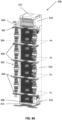
FIG. 3A is a perspective view of anelectrochemical cell column 300, according to various embodiments of the present disclosure, andFIG. 3B is an exploded cross-sectional view of a electrochemical cell stack and a fuel manifolds of theelectrochemical cell column 300. - Referring to
FIGS. 3A , and3B , theelectrochemical cell column 300 may include multiple electrochemical cell stacks 100, aninlet conduit 302, anoutlet conduit 304, abottom termination plate 306, fuel manifolds 400 (e.g., anode splitter plates), and atermination manifold 402. Theelectrochemical cell column 300 may also include acompression assembly 340, and a ceramic frame comprising side baffles 350, atop plate 352, abottom plate 354,bottom connectors 356, andtop connectors 358. Thebottom connectors 356 and thetop connectors 358 connect the side baffles 350 to thebottom plate 354 and thetop plate 352, respectively. - Each
stack 100 may include any suitable number ofelectrochemical cells 30, such as from 10 to 40cells 30, such as from 20 to 35cells 30, or about 30 cells, and a corresponding number ofinterconnects 10 disposed therebetween. Thestacks 100 may also include conductive layers 25, such as a nickel mesh, disposed between the fuel side of eachinterconnect 10 and the anode (e.g., fuel electrode) 37 of an adjacentelectrochemical cell 30, to electrically connect theelectrochemical cells 30 and interconnects 10 of thestack 100. - The
stacks 100 may also include anair end plate 40 disposed at an air side (e.g., adjacent the cathode electrode 33) of an outermost cell of thestack 100, and/or afuel end plate 42 disposed at a fuel side end (e.g., adjacent the anode electrode 37) of an outermost cell of thestack 100. In particular, theend plates stacks 100 to correspondingfuel manifolds 400 ortermination manifold 402. - In various embodiments, the
air end plates 40 may have aflat surface 40F opposing theair channels 8B, as shown inFIG. 3B . Theflat surface 40F lacksfuel channels 8A. Theflat surface 40F may be placed against a correspondingfuel manifold 400, or in the case of thelowermost stack 100, against thebottom termination plate 306, which may be electrically connected to thestacks 100. Thebottom termination plate 306 may operate to seal the fuel holes 20 of the air and/orfuel end plates fuel end plates 42 may have aflat surface 42F opposing thefuel channels 8A. Theflat surface 42F lacksair channels 8B. Theflat surface 42F may be placed against a correspondingfuel manifold 400 or termination manifold 402 (as illustrated inFIG. 3A ). - The
inlet conduit 302 is fluidly connected to fuelmanifolds 400 and thetermination manifold 402 and is configured to provide a fuel stream (i.e., fuel inlet stream) to eachfuel manifold 400 and thetermination manifold 402. Theoutlet conduit 304 is fluidly connected to thefuel manifolds 400 and thetermination manifold 402 and is configured to collect anode exhaust (i.e., the fuel outlet stream) received from thefuel manifolds 400 andtermination manifold 402. Thefuel manifolds 400 and thetermination manifold 402 may be configured to provide a fuel to thestacks 100 and to receive anode fuel exhaust from thestacks 100. For example, thefuel manifolds 400 and thetermination manifold 402 may be fluidly connected to internal fuel riser channels formed by aligning the fuel holes 20 of theinterconnects 10, as discussed above. - The
compression assembly 340 may be disposed between thetop plate 352 and thetermination manifold 402 and may be configured to apply pressure and compress thestacks 100, so as to seal thestacks 100 to adjacent components (e.g.,fuel manifolds 400, thetermination manifold 402 and the bottom termination plate 306). - With regard to the ceramic frame, the
bottom connectors 356 may be configured to connect thebottom plate 354 to the side baffles 350, such that portions of the side baffles 350 directly contact thebottom plate 354. Thetop connectors 358 may be configured to connect thetop plate 352 to the side baffles 350. In various embodiments, thetop connectors 358 may be longer and/or wider than thebottom connectors 356. In particular, thetop connectors 358 may separate thetop plate 352 and the side baffles 350, such thattop plate 352 does not directly contact the side baffles 350. As such, thetop connectors 358 may be configured to increase the height (e.g., length) of thecolumn 300. Therefore, thetop connectors 358 may provide additional space inside of the ceramic frame, such that theuppermost stack 100 may be added to thecolumn 300, without increasing the length of the side baffles 350. In other words, thetop connectors 358 may allow for the use of side baffles 350 that are designed for use in smaller columns. - In various embodiments, each
fuel manifold 400 may directly contact a corresponding pair P1, P2, P3, P4 of thestacks 100. The tworespective stacks 100 of each pair P1, P2, P3, P4 ofstacks 100 are disposed above and below therespective fuel manifold 400, respectively. For example, for thelowermost fuel manifold 400, the first pair P1 of thestacks 100 includes thelowermost stack 100 located directly below thelowermost fuel manifold 400 and a second from the bottom stack located directly above thelowermost fuel manifold 400. Eachfuel manifold 400 may provide fuel to and receive anode exhaust from the corresponding pair P1, P2, P3, P4 of thestacks 100. For example, thelowermost fuel manifold 400 may be fluidly connected to the first pair P1 ofstacks 100, and theuppermost fuel manifold 400 may be fluidly connected to fourth pair P4 ofstacks 100. - The
termination manifold 402 may be disposed on top of theuppermost stack 100 and may be fluidly connected thereto. As such, thetermination manifold 402 may provide fuel to and optionally receive anode exhaust from theuppermost stack 100. Accordingly, two of thestacks 100 may be disposed between each pair ofadjacent fuel manifolds 400. Two of theuppermost stacks 100 are located between theuppermost fuel manifold 400 and thetermination manifold 402. Onestack 100 may be disposed below thelowermost fuel manifold 400. As such, thecolumn 300 may include ninestacks 100 instead of eight due to the addition of thetermination manifold 402. The addition of theninth stack 100 increases the power output of afuel cell column 300. Furthermore, addition of thetermination manifold 402 at the top of thefuel cell column 300 improves the fuel distribution and temperature uniformity along the height of the column. -
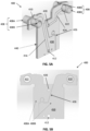
FIG. 4A is a perspective view of a bottom side of atermination manifold 402 that may be included in thecolumn 300 ofFIG. 3A , according to various embodiments of the present disclosure.FIG. 4B is a top view of the top side of thetermination manifold 402 ofFIG. 4A .FIG. 4C is a perspective view of afuel channel 414 ofFIG. 4A . - Referring to
FIGS. 3A ,4A, and 4B , thetermination manifold 402 includes abody 404 andarms 405 that extend horizontally from thebody 404. Thebody 404 may vertically overlap with thestacks 100 and may directly contact the top of theuppermost stack 100.Tubes 408 that extend in a vertical direction may be attached to thearms 405. Thetubes 408 are connected to a respective one of theinlet conduit 302 or theoutlet conduit 304. Thus, thearms 405 may be fluidly connected to the inlet andoutlet conduits tubes 408. In some embodiments, thetubes 408 may be welded or brazed to thearms 405. - The
termination manifold 402 may also include afuel inlet hole 410, afuel outlet hole 412, and afuel channel 414 fluidly connecting the fuel inlet and outlet holes 410, 412. In addition, thetermination manifold 402 may include anodeexhaust inlet hole 420, an anodeexhaust outlet hole 422, and ananode exhaust channel 424 fluidly connecting the anode exhaust inlet and outlet holes 420, 422. Thefuel inlet hole 412 and anodeexhaust outlet hole 420 may be vertically aligned with the fuel holes 20 of thestack 100, in order to form the fuel riser channels that circulate the fuel and anode exhaust within thecolumn 300. - As shown in
FIG. 4C , thefuel channel 414 may have a first width W1 ranging from about 10 mm to about 20 mm. Thefuel channel 414 may be tapered adjacent to thefuel outlet hole 412, such that the width of thefuel channel 414 may be reduced to match the diameter of thefuel outlet hole 412. - In some embodiments, the
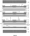
termination manifold 402 may be formed by bonding one or more metal and/or ceramic plates. In one embodiment, thetermination manifold 402 may include alower plate 430, achannel plate 440, and an upper plate 450 (i.e., three plates total). In another embodiment, thetermination manifold 402 may include twochannel plates 440 located between thelower plate 430 and the upper plate 450 (i.e., four plates total). The plates may be brazed or welded together. Thechannels channel plate 440, between thelower plate 430 and theupper plate 450. The fuel holes 410, 412 and the anode exhaust holes 420, 422 may be formed by aligning though-holes that extend through thelower plate 430 and thechannel plate 440. In some embodiments, theupper plate 450 may seal upper ends of the fuel holes 410, 412 and/or the anode exhaust holes 420, 422. Thisupper plate 450 configuration may allow for the omission of an upper terminal plate conventionally used to seal the internally manifolded fuel andexhaust holes 20 ofstack 100 and serve as an electrical terminal for thecolumn 300. Thus, current may be directly extracted from thetermination manifold 402. - In an alternative embodiment, the
fuel inlet hole 410 and the anodeexhaust outlet hole 422 may be through-holes that extend through theplates FIG. 3A , thecolumn 300 may include optional conduit caps 409 that are attached to thetermination manifold 402 and configured to seal upper ends of thefuel inlet hole 410 and the anodeexhaust outlet hole 422. - In various embodiments,
termination manifold 402 may include arelief cut 426, such as a groove or trench, which may be configured to relieve stress generated by thermal expansion and/or contraction of thetermination manifold 402. In some embodiments the relief cut 426 may divide thetermination manifold 402 into interlockingpieces termination manifold 402, such that electrical contact is maintained between thepieces termination manifold 402. - In various embodiments,
termination manifold 402 may include anelectrical contact 452 configured to provide a contact surface for the connection of a stack jumper or wire to thetermination manifold 402, as discussed below with respect toFIG. 6 . In embodiments where the relief cut 426 divides thetermination manifold 402 into separate pieces, theelectrical contact 452 may electrically and/or physically connect opposing sides or pieces of thetermination manifold 402. For example, theelectrical contact 452 may be configured to reduce electrical resistance caused by therelief cut 426. Theelectrical contact 452 may allow current to be extracted from the entirety of thetermination manifold 402 if thecolumn 300 is a fuel cell column, and/or may allow current to be provided to the entirety of thetermination manifold 402 if thecolumn 300 is an electrolyzer column or a reversible fuel cell column. Theelectrical contact 452 may be welded or brazed to theupper plate 450 or may comprise an integral portion of theupper plate 450 that laterally extends past the perimeters of the lower andchannel plates -
FIG. 5A is a perspective view of a bottom side of afuel manifold 400 that may be included in thecolumn 300 ofFIG. 3A , according to various embodiments of the present disclosure.FIG. 5B is a top view of the top side of thefuel manifold 400 ofFIG. 5A .FIG. 5C is a perspective view of afuel channel 416 ofFIG. 5A . Thefuel manifold 400 may be similar to thetermination manifold 402 ofFIGS. 4A and 4B . Accordingly, only the differences therebetween will be discussed in detail. - Referring to
FIGS. 5A, 5B , and5C , the fuel holes 410, 412 and the anode exhaust holes 420, 422 may be through holes that extend through theplates fuel manifold 400. In one embodiment, the fuel manifolds may include twochannel plates 440 located between thelower plate 430 and the upper plate 450 (i.e., four plates total) -
Fuel tubes 408 may be attached to thefuel inlet hole 410 and the anodeexhaust outlet hole 422. In some embodiments, thetubes 408 may includeupper tubes 408A andlower tubes 408B that may be brazed or welded to opposing sides thefuel inlet hole 410 and the anodeexhaust outlet hole 422 to form thefuel tubes 408. - The relief cut 426 may divide the
fuel manifold 400 into interlocking pieces orsections fuel manifold 400 may include afuel channel 416 connecting thefuel inlet hole 410 andfuel outlet hole 412. Thefuel channel 416 may be tapered adjacent to thefuel outlet hole 412, such that the width of thefuel channel 416 may be reduced to match the diameter of thefuel outlet hole 412. - The
fuel channel 416 may have a second width W2 ranging from about 15 mm to about 25 mm. The second width W2 of thefuel channel 416 of thefuel manifold 400 may be wider than the first width W1 of thefuel channel 414 of thetermination manifold 402 by at least 10%, such as by 20 to 60%, for example by 40 to 50%. In an alternative embodiment, thefuel channels 416 of the twolower fuel manifolds 400 may have the first width W1, and the fuel channels of the twoupper fuel manifolds 400 may have the second width W2, which is wider than the first width W1. The present inventors realized that including wider fuel channels in the twoupper fuel manifolds 400 and narrower fuel channels in the twolower fuel manifolds 400 and in theuppermost termination manifold 402 improves the uniformity of fuel utilization among the stacks along the height of thecolumn 300 compared to making allfuel channels column 300 which includes a threeplate termination manifold 402 and fourplate fuel manifolds 400 also improves the uniformity of fuel utilization among the stacks along the height of thecolumn 300. -
FIG. 6 is a perspective view of a twocolumn 300 segment of anelectrochemical cell system 600, according to various embodiments of the present disclosure. Referring toFIG. 6 , thesystem 600 may include at least twofuel cell columns 300 disposed on asystem base 602 and arranged around acentral column 620. Thecolumns 300 may be the same described above with respect toFIGS. 3A-5B . While a segment of twocell columns 300 is shown inFIG. 6 , thesystem 600 may includeadditional columns 300, such as from 6 to 12columns 300 to provide three to six segments. - The
central column 620 may include various fuel processing components, such as an anode recuperator heat exchanger, an anode exhaust cooler heat exchanger, an anode tail gas oxidizer (ATO), optional fuel reformation catalyst, as described, for example, inU.S. Patent Number 9,287,572 B2 issued on March 15, 2016 stacks 100 may be oriented in each segment such that theterminal manifold 402 of onecolumn 300 serves as a negative terminal and theterminal manifold 402 of theother column 300 serves as a positive terminal. The correspondingbottom termination plates 306 of thecolumns 300 may operate as corresponding negative and positive terminals of thecolumns 300 and may be connected tocurrent collector rods 604. In other words, thestacks 100 of onecolumn 300 may be inverted with respect to the stack of theother column 300. - The termination manifolds 402 of the pair of
columns 300 in each segment may be electrically connected to each other by ajumper 610 or wire attached to theelectrical contacts 452 thereof. Thecurrent collecting rods 604 may be electrically connected to an external component, such as apower inverter 616, a resistive balance of plant load, or the like by jumpers orwires 612, to extract power from thecolumns 300 if the columns comprise fuel cell columns, or to provide power to thecolumns 300 if the columns comprise electrolyzer columns. In some embodiments, multiple twocolumn 300 segments may be connected to the same external component in parallel or in series. - According to various embodiments, the termination manifolds provide various unexpected benefits, as compared to conventional stack configurations that utilize only internal fuel manifolds which are located between two stacks in each column. For example, the termination manifolds allow for columns to include an
additional cell stack 100, such that a column may include 9 cell stacks rather than 8. Theadditional cell stack 100 increases the voltage output of a fuel cell column, and thereby increases the power output of a fuel cell system, and/or may increase space utilization efficiency. In addition, the termination manifolds may operate as a column terminal, thereby allowing for the omission of a conventional termination plate, which may reduce stack manufacturing cost and/or complexity. Termination manifolds may be configured with a lower number of plates and/or narrower fuel channels than at least some of the fuel manifold to provide fuel flow rates that increase fuel utilization uniformity along the height of afuel cell column 300. - Fuel cell systems of the embodiments of the present disclosure are designed to reduce greenhouse gas emissions and have a positive impact on the climate.
- Any one or more features from any one or more embodiments may be used in any suitable combination with any one or more features from one or more of the other embodiments. Although the foregoing refers to particular preferred embodiments, it will be understood that the invention is not so limited. It will occur to those of ordinary skill in the art that various modifications may be made to the disclosed embodiments and that such modifications are intended to be within the scope of the invention. All of the publications, patent applications and patents cited herein are incorporated herein by reference in their entirety.
- The invention also refers to the following embodiments, wherein the term "claim" means "embodiment":
- 1. A cell column, comprising:
- vertically aligned stacks comprising electrochemical cells separated by interconnects;
- fuel manifolds disposed between the stacks;
- a termination manifold disposed above an uppermost one of the stacks, wherein the termination manifold comprises an electrical terminal of the cell column, and a fuel channel configured provide fuel to the uppermost one of the stacks; and
- an inlet conduit and an outlet conduit fluidly connected to the fuel manifolds and the termination manifold.
- 2. The cell column of claim 1, wherein the wherein the termination manifold comprises:
- a lower plate;
- a channel plate disposed on the bottom plate;
- a fuel outlet hole that extends through the bottom plate and the channel plate and is configured to provide the fuel to the uppermost one of the stacks;
- an anode exhaust inlet hole that extends through the bottom plate and the channel plate and is configured to receive the anode exhaust from the uppermost one of the stacks; and
- an upper plate disposed over the channel plate and seals upper ends of the fuel inlet hole and the anode exhaust inlet hole.
- 3. The cell column of
claim 2, wherein the upper plate comprises an electrical contact that extends horizontally beyond perimeters of the lower plate and the channel plate. - 4. The cell column of
claim 2, wherein:- the termination manifold comprises a relief cut configured to at least partially divide the termination manifold into first and second pieces; and
- the electrical contact is configured to electrically connect the first and second pieces.
- 5. The cell column of
claim 2, wherein the termination manifold further comprises:- a fuel inlet hole fluidly connected to the inlet conduit; and
- an anode exhaust outlet hole fluidly connected to the outlet conduit.
- 6. The cell column of claim 5, wherein the top plate seals upper ends of the fuel inlet hole and the anode exhaust outlet hole.
- 7. The cell column of claim 5, further comprising conduit caps which seal upper ends of the fuel inlet hole and the anode exhaust outlet hole.
- 8. The cell column of claim 5, wherein:
- the termination manifold further comprises an anode exhaust channel that fluidly connects that anode exhaust inlet hole and the anode exhaust outlet hole; and
- the fuel channel fluidly connects the fuel inlet hole and the fuel outlet hole.
- 9. The cell column of claim 8, wherein the fuel channel and the anode exhaust channel are formed in the single channel plate and extend between the upper plate and the lower plate.
- 10. The cell column of claim 8, wherein the fuel manifolds each comprise:
- a fuel outlet hole and a fuel inlet hole that extend through the fuel manifold;
- an anode exhaust inlet hole and an anode exhaust outlet hole that extend through the fuel manifold;
- a fuel channel that fluidly connects the fuel outlet hole and the fuel inlet hole; and
- an anode exhaust channel that fluidly connects the anode exhaust outlet hole and the anode exhaust inlet hole.
- 11. The cell column of
claim 10, wherein a width of the fuel channels of at least some of the fuel manifolds is greater than a width of the fuel channel of the termination manifold. - 12. The cell column of
claim 11, wherein the width of the fuel channels of upper two of the fuel manifolds is greater than the width of the fuel channel of the termination manifold, and greater than the width of the fuel channels of lower two of the fuel manifolds. - 13. The cell column of
claim 10, wherein:- the termination manifold includes only three plates consisting of the lower plate, the channel plate and the upper plate which is disposed directly on the channel plate; and
- each of the fuel manifolds include four plates comprising two channel plates located between respective lower and upper plates.
- 14. The cell column of claim 1, wherein:
- the column comprises nine of the stacks and four of the fuel manifolds;
- each fuel manifold is located between a pair of the stacks and configured to provide fuel to and receive anode exhaust from the pair of the stacks; and
- no cell stacks are located above the termination manifold.
- 15. The cell column of claim 1, further comprising a bottom termination plate disposed below lowermost one of the stacks, wherein the cell column does not include a top termination plate.
- 16. The cell column of claim 1, further comprising:
- a compression assembly disposed directly on the termination manifold;
- a bottom termination plate disposed below the stacks; and
- a ceramic frame surrounding the stacks, the compression assembly, and the bottom termination plate.
- 17. The cell column of
claim 16, wherein the ceramic frame comprises:- a top plate disposed on the compression assembly;
- a bottom plate disposed under the bottom termination plate;
- side baffles disposed on opposing sides of the stacks;
- bottom connectors connecting the bottom plate to the side baffles; and
- top connectors connecting the top plate to the side baffles.
- 18. The cell column of claim 17, wherein:
- the top connectors are disposed between the top plate and the side baffles, such that the top plate does not directly contact the side baffles; and
- the bottom connectors are disposed between the bottom plate and the side baffles, such that the bottom plate directly contacts the side baffles.
- 19. The cell column of claim 1, wherein:
- the electrochemical cells comprise fuel cells; and
- the cell column comprises a fuel cell column.
- 20. An electrochemical cell system, comprising:
- the cell column of claim 1 located on a base;
- an additional cell column located on the base, wherein the additional cell column comprises an additional termination manifold; and
- a jumper or wire electrically connecting the termination manifold of the cell column to the additional termination manifold of the additional cell column.
Claims (15)
- A cell column, comprising:vertically aligned stacks comprising electrochemical cells separated by interconnects;fuel manifolds disposed between the stacks;a termination manifold disposed above an uppermost one of the stacks, wherein the termination manifold comprises an electrical terminal of the cell column, and a fuel channel configured provide fuel to the uppermost one of the stacks; andan inlet conduit and an outlet conduit fluidly connected to the fuel manifolds and the termination manifold.
- The cell column of claim 1, wherein the wherein the termination manifold comprises:a lower plate;a channel plate disposed on the bottom plate;a fuel outlet hole that extends through the bottom plate and the channel plate and is configured to provide the fuel to the uppermost one of the stacks;an anode exhaust inlet hole that extends through the bottom plate and the channel plate and is configured to receive the anode exhaust from the uppermost one of the stacks; andan upper plate disposed over the channel plate and seals upper ends of the fuel inlet hole and the anode exhaust inlet hole.
- The cell column of claim 2, wherein the upper plate comprises an electrical contact that extends horizontally beyond perimeters of the lower plate and the channel plate.
- The cell column of claim 2, wherein:the termination manifold comprises a relief cut configured to at least partially divide the termination manifold into first and second pieces; andthe electrical contact is configured to electrically connect the first and second pieces.
- The cell column of claim 2, wherein the termination manifold further comprises:a fuel inlet hole fluidly connected to the inlet conduit; andan anode exhaust outlet hole fluidly connected to the outlet conduit.
- The cell column of claim 5, wherein the top plate seals upper ends of the fuel inlet hole and the anode exhaust outlet hole, and further comprising conduit caps which seal upper ends of the fuel inlet hole and the anode exhaust outlet hole.
- The cell column of claim 5, wherein:the termination manifold further comprises an anode exhaust channel that fluidly connects that anode exhaust inlet hole and the anode exhaust outlet hole; andthe fuel channel fluidly connects the fuel inlet hole and the fuel outlet hole.
- The cell column of claim 7, wherein the fuel channel and the anode exhaust channel are formed in the single channel plate and extend between the upper plate and the lower plate.
- The cell column of claim 7, wherein the fuel manifolds each comprise:a fuel outlet hole and a fuel inlet hole that extend through the fuel manifold;an anode exhaust inlet hole and an anode exhaust outlet hole that extend through the fuel manifold;a fuel channel that fluidly connects the fuel outlet hole and the fuel inlet hole; andan anode exhaust channel that fluidly connects the anode exhaust outlet hole and the anode exhaust inlet hole, wherein the width of the fuel channels of upper two of the fuel manifolds is greater than the width of the fuel channel of the termination manifold, and greater than the width of the fuel channels of lower two of the fuel manifolds.
- The cell column of claim 9, wherein:the termination manifold includes only three plates consisting of the lower plate, the channel plate and the upper plate which is disposed directly on the channel plate; andeach of the fuel manifolds include four plates comprising two channel plates located between respective lower and upper plates.
- The cell column of claim 1, wherein:the column comprises nine of the stacks and four of the fuel manifolds;each fuel manifold is located between a pair of the stacks and configured to provide fuel to and receive anode exhaust from the pair of the stacks; andno cell stacks are located above the termination manifold.
- The cell column of claim 1, further comprising a bottom termination plate disposed below lowermost one of the stacks, wherein the cell column does not include a top termination plate.
- The cell column of claim 1, further comprising:a compression assembly disposed directly on the termination manifold;a bottom termination plate disposed below the stacks; anda ceramic frame surrounding the stacks, the compression assembly, and the bottom termination plate,wherein the ceramic frame comprises:a top plate disposed on the compression assembly;a bottom plate disposed under the bottom termination plate;side baffles disposed on opposing sides of the stacks;bottom connectors connecting the bottom plate to the side baffles; andtop connectors connecting the top plate to the side baffles, and wherein:the top connectors are disposed between the top plate and the side baffles, such that the top plate does not directly contact the side baffles; andthe bottom connectors are disposed between the bottom plate and the side baffles, such that the bottom plate directly contacts the side baffles.
- The cell column of claim 1, wherein:the electrochemical cells comprise fuel cells; andthe cell column comprises a fuel cell column.
- An electrochemical cell system, comprising:the cell column of claim 1 located on a base;an additional cell column located on the base, wherein the additional cell column comprises an additional termination manifold; anda jumper or wire electrically connecting the termination manifold of the cell column to the additional termination manifold of the additional cell column.
Applications Claiming Priority (1)
| Application Number | Priority Date | Filing Date | Title |
|---|---|---|---|
| IN202341074800 | 2023-11-02 |
Publications (2)
| Publication Number | Publication Date |
|---|---|
| EP4550490A2 true EP4550490A2 (en) | 2025-05-07 |
| EP4550490A3 EP4550490A3 (en) | 2025-06-11 |
Family
ID=93377900
Family Applications (1)
| Application Number | Title | Priority Date | Filing Date |
|---|---|---|---|
| EP24210355.4A Pending EP4550490A3 (en) | 2023-11-02 | 2024-11-01 | Electrochemical cell columns including termination manifolds |
Country Status (3)
| Country | Link |
|---|---|
| US (1) | US20250149610A1 (en) |
| EP (1) | EP4550490A3 (en) |
| KR (1) | KR20250065245A (en) |
Citations (1)
| Publication number | Priority date | Publication date | Assignee | Title |
|---|---|---|---|---|
| US9287572B2 (en) | 2013-10-23 | 2016-03-15 | Bloom Energy Corporation | Pre-reformer for selective reformation of higher hydrocarbons |
Family Cites Families (4)
| Publication number | Priority date | Publication date | Assignee | Title |
|---|---|---|---|---|
| US7781109B2 (en) * | 2004-09-03 | 2010-08-24 | Gross Karl J | Hydrogen storage and integrated fuel cell assembly |
| US8097378B2 (en) * | 2009-03-11 | 2012-01-17 | Bloom Energy Corporation | Stack seal interface adapter |
| US10211478B2 (en) * | 2015-10-07 | 2019-02-19 | Bloom Energy Corporation | Fuel cell stack column including stress-relief components |
| US11271240B2 (en) * | 2019-05-28 | 2022-03-08 | Bloom Energy Corporation | Fuel cell column containing electrically insulated fuel manifold and manifold jumper |
-
2024
- 2024-11-01 EP EP24210355.4A patent/EP4550490A3/en active Pending
- 2024-11-01 US US18/934,599 patent/US20250149610A1/en active Pending
- 2024-11-01 KR KR1020240153191A patent/KR20250065245A/en active Pending
Patent Citations (1)
| Publication number | Priority date | Publication date | Assignee | Title |
|---|---|---|---|---|
| US9287572B2 (en) | 2013-10-23 | 2016-03-15 | Bloom Energy Corporation | Pre-reformer for selective reformation of higher hydrocarbons |
Also Published As
| Publication number | Publication date |
|---|---|
| KR20250065245A (en) | 2025-05-12 |
| US20250149610A1 (en) | 2025-05-08 |
| EP4550490A3 (en) | 2025-06-11 |
Similar Documents
| Publication | Publication Date | Title |
|---|---|---|
| US11870121B2 (en) | Fuel cell column including stress mitigation structures | |
| US20130130144A1 (en) | Solid oxide fuel cell | |
| EP3270450A1 (en) | Fuel cell stack | |
| US12506169B2 (en) | Fuel plenum and fuel cell stack including same | |
| JP2020009744A (en) | Electrochemical reaction unit and electrochemical reaction cell stack | |
| US10693153B2 (en) | Interconnector-electrochemical reaction unit cell composite body, electrochemical reaction cell stack, and method of manufacturing interconnector-electrochemical reaction unit cell composite body | |
| US20250030012A1 (en) | Fuel cell interconnect optimized for operation in hydrogen fuel | |
| US11764389B2 (en) | Fuel cell manifold having an embedded dielectric layer and methods of making thereof | |
| JP2024519724A (en) | Method for manufacturing SOEC/SOFC type solid oxide stacks and related stacks | |
| EP2860805B1 (en) | Current collector plate for fuel cell and stack structure comprising same | |
| US10476087B2 (en) | Fuel-cell power generation unit and fuel-cell stack | |
| EP4550490A2 (en) | Electrochemical cell columns including termination manifolds | |
| US20110294041A1 (en) | Solid oxide fuel cell with special cell geometry | |
| EP2933864B1 (en) | Stack structure for fuel cell | |
| JP2019204592A (en) | Electrochemical reaction unit and electrochemical cell stack | |
| JP6797153B2 (en) | Electrochemical reaction cell stack | |
| US11158878B2 (en) | Electrochemical reaction cell stack | |
| US20240332560A1 (en) | Electrochemical cell stacks including interconnect end plates | |
| JP6917193B2 (en) | Electrochemical reaction unit and electrochemical reaction cell stack | |
| EP4557414A2 (en) | Internally manifolded interconnects with plural flow directions and electrochemical cell column including same | |
| US20250323304A1 (en) | Electrochemical cell stacks including multi-diameter mesh contact layer | |
| JP7159249B2 (en) | Electrochemical reaction cell stack and IC-single cell composite | |
| JP6885786B2 (en) | Electrochemical reaction unit and electrochemical reaction cell stack | |
| JP2018185957A (en) | Electrochemical reaction unit and electrochemical reaction cell stack | |
| CA3253602A1 (en) | Internally manifolded interconnects with plural flow directions and electrochemical cell column including same |
Legal Events
| Date | Code | Title | Description |
|---|---|---|---|
| PUAI | Public reference made under article 153(3) epc to a published international application that has entered the european phase |
Free format text: ORIGINAL CODE: 0009012 |
|
| STAA | Information on the status of an ep patent application or granted ep patent |
Free format text: STATUS: THE APPLICATION HAS BEEN PUBLISHED |
|
| AK | Designated contracting states |
Kind code of ref document: A2 Designated state(s): AL AT BE BG CH CY CZ DE DK EE ES FI FR GB GR HR HU IE IS IT LI LT LU LV MC ME MK MT NL NO PL PT RO RS SE SI SK SM TR |
|
| PUAL | Search report despatched |
Free format text: ORIGINAL CODE: 0009013 |
|
| AK | Designated contracting states |
Kind code of ref document: A3 Designated state(s): AL AT BE BG CH CY CZ DE DK EE ES FI FR GB GR HR HU IE IS IT LI LT LU LV MC ME MK MT NL NO PL PT RO RS SE SI SK SM TR |
|
| RIC1 | Information provided on ipc code assigned before grant |
Ipc: H01M 8/12 20160101ALN20250507BHEP Ipc: H01M 8/248 20160101ALN20250507BHEP Ipc: H01M 8/2484 20160101ALI20250507BHEP Ipc: H01M 8/249 20160101ALI20250507BHEP Ipc: H01M 8/2485 20160101AFI20250507BHEP |
|
| STAA | Information on the status of an ep patent application or granted ep patent |
Free format text: STATUS: REQUEST FOR EXAMINATION WAS MADE |
|
| 17P | Request for examination filed |
Effective date: 20251210 |