EP4550440A1 - Electrochemical device and manufacturing method therefor, and electronic device - Google Patents
Electrochemical device and manufacturing method therefor, and electronic device Download PDFInfo
- Publication number
- EP4550440A1 EP4550440A1 EP23830515.5A EP23830515A EP4550440A1 EP 4550440 A1 EP4550440 A1 EP 4550440A1 EP 23830515 A EP23830515 A EP 23830515A EP 4550440 A1 EP4550440 A1 EP 4550440A1
- Authority
- EP
- European Patent Office
- Prior art keywords
- negative electrode
- electrode plate
- active material
- lithium
- region
- Prior art date
- Legal status (The legal status is an assumption and is not a legal conclusion. Google has not performed a legal analysis and makes no representation as to the accuracy of the status listed.)
- Pending
Links
Images


Classifications
-
- H—ELECTRICITY
- H01—ELECTRIC ELEMENTS
- H01M—PROCESSES OR MEANS, e.g. BATTERIES, FOR THE DIRECT CONVERSION OF CHEMICAL ENERGY INTO ELECTRICAL ENERGY
- H01M4/00—Electrodes
- H01M4/02—Electrodes composed of, or comprising, active material
- H01M4/13—Electrodes for accumulators with non-aqueous electrolyte, e.g. for lithium-accumulators; Processes of manufacture thereof
-
- H—ELECTRICITY
- H01—ELECTRIC ELEMENTS
- H01M—PROCESSES OR MEANS, e.g. BATTERIES, FOR THE DIRECT CONVERSION OF CHEMICAL ENERGY INTO ELECTRICAL ENERGY
- H01M10/00—Secondary cells; Manufacture thereof
- H01M10/04—Construction or manufacture in general
- H01M10/0431—Cells with wound or folded electrodes
-
- H—ELECTRICITY
- H01—ELECTRIC ELEMENTS
- H01M—PROCESSES OR MEANS, e.g. BATTERIES, FOR THE DIRECT CONVERSION OF CHEMICAL ENERGY INTO ELECTRICAL ENERGY
- H01M10/00—Secondary cells; Manufacture thereof
- H01M10/05—Accumulators with non-aqueous electrolyte
- H01M10/052—Li-accumulators
- H01M10/0525—Rocking-chair batteries, i.e. batteries with lithium insertion or intercalation in both electrodes; Lithium-ion batteries
-
- H—ELECTRICITY
- H01—ELECTRIC ELEMENTS
- H01M—PROCESSES OR MEANS, e.g. BATTERIES, FOR THE DIRECT CONVERSION OF CHEMICAL ENERGY INTO ELECTRICAL ENERGY
- H01M10/00—Secondary cells; Manufacture thereof
- H01M10/05—Accumulators with non-aqueous electrolyte
- H01M10/058—Construction or manufacture
- H01M10/0583—Construction or manufacture of accumulators with folded construction elements except wound ones, i.e. folded positive or negative electrodes or separators, e.g. with "Z"-shaped electrodes or separators
-
- H—ELECTRICITY
- H01—ELECTRIC ELEMENTS
- H01M—PROCESSES OR MEANS, e.g. BATTERIES, FOR THE DIRECT CONVERSION OF CHEMICAL ENERGY INTO ELECTRICAL ENERGY
- H01M10/00—Secondary cells; Manufacture thereof
- H01M10/05—Accumulators with non-aqueous electrolyte
- H01M10/058—Construction or manufacture
- H01M10/0585—Construction or manufacture of accumulators having only flat construction elements, i.e. flat positive electrodes, flat negative electrodes and flat separators
-
- H—ELECTRICITY
- H01—ELECTRIC ELEMENTS
- H01M—PROCESSES OR MEANS, e.g. BATTERIES, FOR THE DIRECT CONVERSION OF CHEMICAL ENERGY INTO ELECTRICAL ENERGY
- H01M10/00—Secondary cells; Manufacture thereof
- H01M10/05—Accumulators with non-aqueous electrolyte
- H01M10/058—Construction or manufacture
- H01M10/0587—Construction or manufacture of accumulators having only wound construction elements, i.e. wound positive electrodes, wound negative electrodes and wound separators
-
- H—ELECTRICITY
- H01—ELECTRIC ELEMENTS
- H01M—PROCESSES OR MEANS, e.g. BATTERIES, FOR THE DIRECT CONVERSION OF CHEMICAL ENERGY INTO ELECTRICAL ENERGY
- H01M4/00—Electrodes
- H01M4/02—Electrodes composed of, or comprising, active material
- H01M4/04—Processes of manufacture in general
- H01M4/0438—Processes of manufacture in general by electrochemical processing
- H01M4/044—Activating, forming or electrochemical attack of the supporting material
- H01M4/0445—Forming after manufacture of the electrode, e.g. first charge, cycling
-
- H—ELECTRICITY
- H01—ELECTRIC ELEMENTS
- H01M—PROCESSES OR MEANS, e.g. BATTERIES, FOR THE DIRECT CONVERSION OF CHEMICAL ENERGY INTO ELECTRICAL ENERGY
- H01M4/00—Electrodes
- H01M4/02—Electrodes composed of, or comprising, active material
- H01M4/13—Electrodes for accumulators with non-aqueous electrolyte, e.g. for lithium-accumulators; Processes of manufacture thereof
- H01M4/131—Electrodes based on mixed oxides or hydroxides, or on mixtures of oxides or hydroxides, e.g. LiCoOx
-
- H—ELECTRICITY
- H01—ELECTRIC ELEMENTS
- H01M—PROCESSES OR MEANS, e.g. BATTERIES, FOR THE DIRECT CONVERSION OF CHEMICAL ENERGY INTO ELECTRICAL ENERGY
- H01M4/00—Electrodes
- H01M4/02—Electrodes composed of, or comprising, active material
- H01M4/13—Electrodes for accumulators with non-aqueous electrolyte, e.g. for lithium-accumulators; Processes of manufacture thereof
- H01M4/133—Electrodes based on carbonaceous material, e.g. graphite-intercalation compounds or CFx
-
- H—ELECTRICITY
- H01—ELECTRIC ELEMENTS
- H01M—PROCESSES OR MEANS, e.g. BATTERIES, FOR THE DIRECT CONVERSION OF CHEMICAL ENERGY INTO ELECTRICAL ENERGY
- H01M4/00—Electrodes
- H01M4/02—Electrodes composed of, or comprising, active material
- H01M4/13—Electrodes for accumulators with non-aqueous electrolyte, e.g. for lithium-accumulators; Processes of manufacture thereof
- H01M4/134—Electrodes based on metals, Si or alloys
-
- H—ELECTRICITY
- H01—ELECTRIC ELEMENTS
- H01M—PROCESSES OR MEANS, e.g. BATTERIES, FOR THE DIRECT CONVERSION OF CHEMICAL ENERGY INTO ELECTRICAL ENERGY
- H01M4/00—Electrodes
- H01M4/02—Electrodes composed of, or comprising, active material
- H01M4/13—Electrodes for accumulators with non-aqueous electrolyte, e.g. for lithium-accumulators; Processes of manufacture thereof
- H01M4/139—Processes of manufacture
- H01M4/1391—Processes of manufacture of electrodes based on mixed oxides or hydroxides, or on mixtures of oxides or hydroxides, e.g. LiCoOx
-
- H—ELECTRICITY
- H01—ELECTRIC ELEMENTS
- H01M—PROCESSES OR MEANS, e.g. BATTERIES, FOR THE DIRECT CONVERSION OF CHEMICAL ENERGY INTO ELECTRICAL ENERGY
- H01M4/00—Electrodes
- H01M4/02—Electrodes composed of, or comprising, active material
- H01M4/13—Electrodes for accumulators with non-aqueous electrolyte, e.g. for lithium-accumulators; Processes of manufacture thereof
- H01M4/139—Processes of manufacture
- H01M4/1393—Processes of manufacture of electrodes based on carbonaceous material, e.g. graphite-intercalation compounds or CFx
-
- H—ELECTRICITY
- H01—ELECTRIC ELEMENTS
- H01M—PROCESSES OR MEANS, e.g. BATTERIES, FOR THE DIRECT CONVERSION OF CHEMICAL ENERGY INTO ELECTRICAL ENERGY
- H01M4/00—Electrodes
- H01M4/02—Electrodes composed of, or comprising, active material
- H01M4/36—Selection of substances as active materials, active masses, active liquids
- H01M4/362—Composites
- H01M4/364—Composites as mixtures
-
- H—ELECTRICITY
- H01—ELECTRIC ELEMENTS
- H01M—PROCESSES OR MEANS, e.g. BATTERIES, FOR THE DIRECT CONVERSION OF CHEMICAL ENERGY INTO ELECTRICAL ENERGY
- H01M4/00—Electrodes
- H01M4/02—Electrodes composed of, or comprising, active material
- H01M4/36—Selection of substances as active materials, active masses, active liquids
- H01M4/48—Selection of substances as active materials, active masses, active liquids of inorganic oxides or hydroxides
- H01M4/483—Selection of substances as active materials, active masses, active liquids of inorganic oxides or hydroxides for non-aqueous cells
-
- H—ELECTRICITY
- H01—ELECTRIC ELEMENTS
- H01M—PROCESSES OR MEANS, e.g. BATTERIES, FOR THE DIRECT CONVERSION OF CHEMICAL ENERGY INTO ELECTRICAL ENERGY
- H01M4/00—Electrodes
- H01M4/02—Electrodes composed of, or comprising, active material
- H01M4/36—Selection of substances as active materials, active masses, active liquids
- H01M4/58—Selection of substances as active materials, active masses, active liquids of inorganic compounds other than oxides or hydroxides, e.g. sulfides, selenides, tellurides, halogenides or LiCoFy; of polyanionic structures, e.g. phosphates, silicates or borates
- H01M4/583—Carbonaceous material, e.g. graphite-intercalation compounds or CFx
- H01M4/587—Carbonaceous material, e.g. graphite-intercalation compounds or CFx for inserting or intercalating light metals
-
- H—ELECTRICITY
- H01—ELECTRIC ELEMENTS
- H01M—PROCESSES OR MEANS, e.g. BATTERIES, FOR THE DIRECT CONVERSION OF CHEMICAL ENERGY INTO ELECTRICAL ENERGY
- H01M4/00—Electrodes
- H01M4/02—Electrodes composed of, or comprising, active material
- H01M2004/021—Physical characteristics, e.g. porosity, surface area
-
- H—ELECTRICITY
- H01—ELECTRIC ELEMENTS
- H01M—PROCESSES OR MEANS, e.g. BATTERIES, FOR THE DIRECT CONVERSION OF CHEMICAL ENERGY INTO ELECTRICAL ENERGY
- H01M4/00—Electrodes
- H01M4/02—Electrodes composed of, or comprising, active material
- H01M2004/026—Electrodes composed of, or comprising, active material characterised by the polarity
- H01M2004/027—Negative electrodes
-
- Y—GENERAL TAGGING OF NEW TECHNOLOGICAL DEVELOPMENTS; GENERAL TAGGING OF CROSS-SECTIONAL TECHNOLOGIES SPANNING OVER SEVERAL SECTIONS OF THE IPC; TECHNICAL SUBJECTS COVERED BY FORMER USPC CROSS-REFERENCE ART COLLECTIONS [XRACs] AND DIGESTS
- Y02—TECHNOLOGIES OR APPLICATIONS FOR MITIGATION OR ADAPTATION AGAINST CLIMATE CHANGE
- Y02E—REDUCTION OF GREENHOUSE GAS [GHG] EMISSIONS, RELATED TO ENERGY GENERATION, TRANSMISSION OR DISTRIBUTION
- Y02E60/00—Enabling technologies; Technologies with a potential or indirect contribution to GHG emissions mitigation
- Y02E60/10—Energy storage using batteries
-
- Y—GENERAL TAGGING OF NEW TECHNOLOGICAL DEVELOPMENTS; GENERAL TAGGING OF CROSS-SECTIONAL TECHNOLOGIES SPANNING OVER SEVERAL SECTIONS OF THE IPC; TECHNICAL SUBJECTS COVERED BY FORMER USPC CROSS-REFERENCE ART COLLECTIONS [XRACs] AND DIGESTS
- Y02—TECHNOLOGIES OR APPLICATIONS FOR MITIGATION OR ADAPTATION AGAINST CLIMATE CHANGE
- Y02P—CLIMATE CHANGE MITIGATION TECHNOLOGIES IN THE PRODUCTION OR PROCESSING OF GOODS
- Y02P70/00—Climate change mitigation technologies in the production process for final industrial or consumer products
- Y02P70/50—Manufacturing or production processes characterised by the final manufactured product
Definitions
- This application relates to the field of electrochemical technologies, and in particular, to an electrochemical apparatus, a manufacturing method thereof, and an electronic apparatus.
- Lithium-ion batteries feature high operating voltage, high energy density, long cycle life, and wide operating temperature range. These outstanding characteristics have led to widespread application of lithium-ion batteries in three major fields including consumer electronics, power battery, and energy storage.
- lithium can be supplemented on surfaces of the negative electrode plates.
- the prelithiation negative electrode plates may be prone to lithium precipitation, especially at the edges, affecting the safety of lithium-ion batteries.
- This application is intended to provide an electrochemical apparatus, a manufacturing method thereof, and an electronic apparatus, so as to reduce the risk of lithium precipitation in negative electrode plates and improve the safety and reliability of electrochemical apparatuses.
- Specific technical solutions are as follows:
- a first aspect of this application provides an electrochemical apparatus including an electrode assembly, where the electrode assembly includes a positive electrode plate and a negative electrode plate; the positive electrode plate includes a positive electrode current collector and a first positive electrode active material layer disposed on a surface of the positive electrode current collector; the negative electrode plate includes a negative electrode current collector and a first negative electrode active material layer disposed on a surface of the negative electrode current collector; and the first negative electrode active material layer includes a prelithiation region and an non-prelithiation region, the non-prelithiation region being a region located within a region of the first negative electrode active material layer and having no area overlapping with the prelithiation region; where the first negative electrode active material layer has a dimension of B 1 mm in a width direction, the first positive electrode active material layer has a dimension of B 2 mm in the width direction, and distance between an edge of the first negative electrode active material layer extending along a length direction and an adjacent edge of the prelithiation region extending along the length direction is B 4 mm, where 0.15
- an non-prelithiation region is provided on the first negative electrode active material layer in the edge region of the negative electrode plate to reduce the risk of lithium precipitation on the negative electrode plate.
- the non-prelithiation region allows more lithium ions from the positive electrode to be embedded compared to the prelithiation region, and local capacity ratio in the edge region of the negative electrode plate is increased, allowing accommodation of more lithium ions from the edge of the opposite positive electrode plate. This can reduce the risk of lithium precipitation at the edge of the negative electrode plate in the width direction, thereby enhancing the safety and reliability of the electrochemical apparatus and balancing the energy density within the electrochemical apparatus.
- the first negative electrode active material layer has a dimension of A 1 mm in the length direction
- the first positive electrode active material layer has a dimension of A 2 mm in the length direction
- distance between an edge of the first negative electrode active material layer extending along the width direction and an adjacent edge of the prelithiation region extending along the width direction is A 4 mm, where 0.15 ⁇ A 4 ⁇ 1/2 ⁇ (A 1 - A 2 ) + 1. Controlling A 4 within the above range can reduce the risk of lithium precipitation at the edge of the negative electrode plate in the length direction, thereby improving the safety and reliability of the electrochemical apparatus.
- the prelithiation region when viewed from a thickness direction of the negative electrode plate, the prelithiation region has striped portions; along an arrangement direction of multiple striped portions, the striped portion has a dimension of 0.1 mm to 2 mm; and/or in the thickness direction of the negative electrode plate, the striped portion has a thickness of 0.04 ⁇ m to 0.5 ⁇ m.
- the negative electrode plate having the above features can improve the initial coulombic efficiency of the negative electrode plate, helping to improve the energy density of the electrochemical apparatus and the manufacturing efficiency of the prelithiation region.
- a material of the prelithiation region includes at least one of lithium carbonate, lithium oxide, lithium nitride, or lithium fluoride.
- the lithium supplement process of the negative electrode plate due to the high activity of lithium metal, it reacts with the surrounding air and undergoes reactions in the formation process of the electrochemical apparatus.
- a layer of lithium-containing compound is formed on the surface of the first negative electrode active material layer.
- the main components of the lithium-containing compound include at least one of lithium carbonate, lithium oxide, lithium nitride, or lithium fluoride.
- the surface resistance of the negative electrode plate can be increased, reducing the risk of short circuits and the short-circuit current. Furthermore, the material covering the prelithiation region on the surface of the negative electrode active material can reduce the risk of damage to the solid electrolyte interface film.
- the first negative electrode active material layer includes a negative electrode active material
- the negative electrode active material includes a silicon-based material, conducive to increasing the energy density of the electrochemical apparatus.
- the electrode assembly is a wound structure
- the width direction is an extension direction of a short side of an unwound electrode plate
- the length direction is an extension direction of a long side of the unwound electrode plate, the electrode plate including the positive electrode plate and the negative electrode plate.
- the wound structure is advantageous for the large-scale and fast manufacturing of the electrode assembly.
- a 4 and B 4 can be set to satisfy such ranges by setting a larger and suitable margin in the length direction and a smaller and suitable margin in the width direction, which is conducive to improving the manufacturing efficiency and satisfying the manufacturing requirements, further reducing the risk of lithium precipitation on the negative electrode plate and reducing the impact on the capacity of the electrochemical apparatus.
- the electrode assembly is a stacked structure
- the width direction is an extension direction of a short side of an electrode plate
- the length direction is an extension direction of a long side of the electrode plate, the electrode plate including the positive electrode plate and the negative electrode plate.
- the stacked structure facilitates the utilization of space by the electrode assembly, thereby increasing the design capacity of the electrochemical apparatus.
- a 4 and B 4 can be set to satisfy such ranges by setting suitable margins in the length direction and the width direction, thereby reducing the risk of lithium precipitation on the negative electrode plate and reducing the impact on the capacity of the electrochemical apparatus.
- a second aspect of this application provides a method for manufacturing the electrochemical apparatus according to the first aspect of this application.
- the method includes the following steps:
- the electrochemical apparatus manufactured using the method provided in the second aspect of this application can reduce the risk of lithium precipitation on the negative electrode plate and improve the safety and reliability of the lithium-ion battery.
- the process of assembling the electrode assembly includes: stacking the negative electrode plate and the positive electrode plate to obtain the electrode assembly, or stacking the negative electrode plate and the positive electrode plate and winding the resulting stack to obtain the electrode assembly.
- At least one of lithium foil or lithium powder is used on the surface of the first negative electrode active material layer to provide the prelithiation region on the first negative electrode active material layer.
- a third aspect of this application provides an electronic apparatus including the electrochemical apparatus according to the first aspect of this application.
- the electrochemical apparatus provided in this application has good safety and reliability, so the electronic apparatus provided in this application also has good safety and reliability.
- This application provides an electrochemical apparatus, a manufacturing method thereof, and an electronic apparatus.
- the non-prelithiation region is provided in the first negative electrode active material layer in the edge region of the negative electrode plate to reduce the risk of lithium precipitation on the negative electrode plate.
- the non-prelithiation region allows more lithium ions from the positive electrode to be embedded compared to the prelithiation region.
- local capacity ratio in the edge region of the negative electrode plate is increased, allowing accommodation of more lithium ions from the edge of the opposite positive electrode plate. This can reduce the risk of lithium precipitation at the edge of the negative electrode plate in the width direction, thereby enhancing the safety and reliability of the electrochemical apparatus.
- a lithium-ion battery is used as an example of an electrochemical apparatus to explain this application.
- the electrochemical apparatus in this application is not limited to the lithium-ion battery.
- electrochemical apparatus design In order to reduce the risk of lithium precipitation during use, electrochemical apparatus design generally requires the area of the negative electrode plate to be greater than the area of the positive electrode plate.
- the portion of the negative electrode plate that exceeds the positive electrode plate is referred to as an edge overhang portion of the negative electrode plate.
- the edge overhang portion of the negative electrode plate cannot be pressed; otherwise, the adhesion between the separator in this region and the negative electrode plate becomes weaker and the interface gap between the separator and the negative electrode plate becomes larger.
- the electrolyte is consumed, a lack of electrolyte is likely to occur at the edge of the negative electrode plate, leading to lithium precipitation at the edge of the negative electrode plate.
- the electrochemical apparatus swells during the cycling process, causing the electrode plate to extend in the width direction and length direction, and the electrode assembly to continuously squeeze the housing, leading to deformation of the electrochemical apparatus. Therefore, a certain gap needs to be reserved between the electrode assembly and the housing.
- electrolyte injection there is a relatively larger amount of electrolyte at the edge of the electrode assembly, leading to an increased amount of film-forming additives in the electrolyte at the edge. This in turn results in higher film-forming impedance at the edge of the electrode plate during the formation and aging stages. Therefore, lithium precipitation easily occurs at the edge of the negative electrode plate during the cycling process.
- typically lithium is supplemented to the negative electrode plates to improve the initial coulombic efficiency of the negative electrode plates.
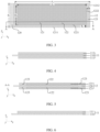
- the electrochemical apparatus includes an electrode assembly 10, and the electrode assembly 10 includes a positive electrode plate 11 and a negative electrode plate 12.
- FIG. 4 is a schematic structural diagram of the positive electrode plate 11 viewed along its thickness direction
- FIG. 5 is a cross-sectional view of the negative electrode plate 12 in its thickness direction along the A-A section shown in FIG. 3 .
- the positive electrode plate 11 includes a positive electrode current collector 110 and a first positive electrode active material layer 111 disposed on a surface of the positive electrode current collector 110.
- the negative electrode plate 12 includes a negative electrode current collector 120 and a first negative electrode active material layer 121 disposed on a surface of the negative electrode current collector 120.
- the first negative electrode active material layer 121 includes a prelithiation region 122 and an non-prelithiation region 123, the non-prelithiation region 123 being a region located within a region of the first negative electrode active material layer 121 and having no area overlapping with the prelithiation region 122. As shown in FIG.
- the first negative electrode active material layer 121 has a dimension of B 1 mm in a width direction (direction y), and the first positive electrode active material layer 111 has a dimension of B 2 mm in the width direction (direction y); and distance between an edge 1211 of the first negative electrode active material layer 121 extending along a length direction (direction x) and an adjacent edge 1221 of the prelithiation region extending along the length direction (direction x) is B 4 mm, where 0.15 ⁇ B 4 ⁇ 1/2 ⁇ (B 1 - B 2 ) + 1.
- This application controls the amount of lithium supplemented in different regions on the surface of the negative electrode plate 12, so as to supplementing lithium evenly in the normal regions while supplementing no lithium at the edge of the negative electrode plate 12. Because no lithium is supplemented at the edge of the negative electrode plate 12, this location has a relatively larger local capacity, allowing accommodation of more lithium ions from the positive electrode plate 11.
- the edge of the negative electrode plate 12 receives the lithium ions from the corresponding positive electrode plate 11 that will participate in formation of solid electrolyte interface films and silicates. However, these lithium ions become inactive lithium and cannot return to the positive electrode plate 11, leading to a reduction in the reversible lithium ions at the edge of the positive electrode plate 11.
- the edge of the negative electrode plate 12 can accept lithium ions from the edge of the opposite positive electrode plate 11. This can reduce the risk of lithium precipitation at the edge of the negative electrode plate 12 during the cycling process of the electrochemical apparatus.
- the first negative electrode active material layer 121 has a dimension of A 1 mm in the length direction (direction x), and the first positive electrode active material layer 111 has a dimension of A 2 mm in the length direction (direction x); and distance between an edge 1212 of the first negative electrode active material layer 121 extending along the width direction (direction y) and an adjacent edge 1222 of the prelithiation region extending along the width direction (direction y) is A 4 mm, where 0.15 ⁇ A 4 ⁇ 1/2 ⁇ (A 1 - A 2 ) + 1. Controlling A 4 within the above range can reduce the risk of lithium precipitation at the edge of the negative electrode plate 12 in the length direction, thereby improving the safety and reliability of the electrochemical apparatus.
- the electrode assembly 10 is a wound structure, where 0.15 ⁇ A 4 ⁇ 5, and 0.15 ⁇ B 4 ⁇ 1.75. Controlling the dimension of the non-prelithiation region 123 to satisfy the above relationships can reduce the risk of lithium precipitation on the negative electrode plate 12, improve the safety and reliability of the electrochemical apparatus, and reduce the influence of the otherwise too-large non-prelithiation region 123 on the capacity of the electrochemical apparatus.
- the electrode assembly 10 is a stacked structure, where 0.15 ⁇ A 4 ⁇ 1.75, and 0.15 ⁇ B 4 ⁇ 1.6. Controlling the dimension of the non-prelithiation region 123 to satisfy the above relationships can further reduce the influence of the otherwise too-large non-prelithiation region 123 on the capacity of the electrochemical apparatus.
- FIG. 6 is a schematic structural diagram of the positive electrode plate 11 when viewed from its thickness direction
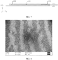
- FIG. 7 is a cross-sectional view of the negative electrode plate along A-A (as shown in FIG. 3 ) in its thickness direction.
- the positive electrode plate 11 includes a positive electrode current collector 110 and a first positive electrode active material layer 111 disposed on a surface of the positive electrode current collector 110.
- the negative electrode plate 12 includes a negative electrode current collector 120 and a first negative electrode active material layer 121 disposed on a surface of the negative electrode current collector 120.
- Such configuration can also achieve the objectives of this application.
- the prelithiation region 122 when viewed from a thickness direction (direction z) of the negative electrode plate 12, the prelithiation region 122 has striped portions; along an arrangement direction of multiple striped portions, the striped portion has a dimension of 0.1 mm to 2 mm; and/or in the thickness direction of the negative electrode plate 12, the striped portion has a thickness of 0.04 ⁇ m to 0.5 ⁇ m.
- the negative electrode plate having the above features can improve the initial coulombic efficiency of the negative electrode plate 12, helping to improve the energy density of the electrochemical apparatus.
- the striped portion in the first direction, has a width of 0.1 mm to 2 mm, and in the thickness direction, the striped portion has a thickness of 0.04 ⁇ m to 0.5 ⁇ m; in an embodiment, in the first direction, the striped portion has a width of 0.1 mm to 2 mm; and in an embodiment, in the thickness direction, the striped portion has a thickness of 0.04 ⁇ m to 0.5 ⁇ m.
- the striped portion refers to a lithium strip with striped gaps formed during calendering of lithium metal when lithium is supplemented through lithium metal foil.
- the lithium strip with striped gaps formed can be maintained, so the striped portion can be observed from the thickness direction (direction z) of the negative electrode plate 12.
- the striped portions remain on the surface of the negative electrode plate 12.
- the prelithiation region 122 on the negative electrode plate 12 has striped portions, as shown in FIG. 8 , while the non-prelithiation region 123 at the edge of the negative electrode plate 12 does not have striped portions, as shown in FIG. 9 .
- the prelithiation region 122 forms one lithium-containing compound layer on the surface of the negative electrode active material, as shown in the layered structure between two black dashed lines in FIG. 10 .
- the lithium-containing compound layer has a thickness of 0.04 ⁇ m to 0.5 ⁇ m.
- the surface resistance of the negative electrode plate 12 can be increased, reducing the risk of short circuits and the short-circuit current. Furthermore, the material covering the prelithiation region 122 on the surface of the negative electrode active material can reduce the risk of damage to the solid electrolyte interface film.
- the first negative electrode active material layer 121 includes a negative electrode active material
- the negative electrode active material includes a silicon-based material.
- the silicon-based material includes at least one of silicon, silicon-oxygen compound (SiO x , 0 ⁇ x ⁇ 2), silicon alloy, or silicon-carbon compound.
- the negative electrode active material in this application may further include at least one of graphite, mesocarbon microbeads (MCMB), hard carbon, soft carbon, Li-Sn alloy, Li-Sn-O alloy, Sn, SnO, SnO 2 , spinel-structure lithium titanate Li 4 Ti 5 O 12 , Li-Al alloy, lithium metal, or the like.
- MCMB mesocarbon microbeads
- the electrode assembly usually has long and short edges when unwound.
- the electrode assembly is a wound structure
- the width direction is an extension direction of a short side of an unwound electrode plate
- the length direction is an extension direction of a long side of the unwound electrode plate.
- the electrode plate of this application includes the positive electrode plate 11 and the negative electrode plate 12.
- the electrode plates are usually stacked layer by layer.
- the electrode assembly is a stacked structure
- the width direction is an extension direction of a short side of an electrode plate
- the length direction is an extension direction of a long side of the electrode plate.
- the foregoing electrode plate includes the positive electrode plate 11 and the negative electrode plate 12.
- the width direction is an extension direction of one side of the electrode plate
- the length direction is a direction perpendicular to the width direction on a plane where the electrode plate is located.
- the electrochemical apparatus of this application is not particularly limited and may include any apparatus in which an electrochemical reaction takes place.
- the electrochemical apparatus may include but is not limited to a lithium-ion secondary battery (lithium-ion battery), a lithium polymer secondary battery, or a lithium-ion polymer secondary battery.
- the electrode assembly structure of the lithium-ion battery of this application includes a wound structure, a stacked structure, or the like.
- the lithium-ion battery structure of this application includes but is not limited to a pouch lithium-ion battery, prismatic hard-shell battery, or a cylindrical hard-shell battery, or the like.
- the negative electrode current collector 120 is not particularly limited in this application, provided that the objectives of this application can be achieved.
- the negative electrode current collector 120 may include copper foil, copper alloy foil, nickel foil, stainless steel foil, titanium foil, foamed nickel, foamed copper, a composite current collector, or the like.
- the thickness of the negative electrode current collector 120 is not particularly limited in this application, provided that the objectives of this application can be achieved.
- the thickness of the negative electrode current collector 120 is 4 ⁇ m to 10 ⁇ m.
- the first negative electrode active material layer 121 may be provided on one or two surfaces of the negative electrode current collector 120 in a thickness direction of the negative electrode current collector 120. It should be noted that the "surface" herein may be an entire region of the negative electrode current collector 120, or may be a partial region of the negative electrode current collector 120. This is not particularly limited in this application, provided that the objectives of this application can be achieved.
- a first negative electrode active material layer 121 is provided on a surface of the negative electrode current collector 120, or a functional layer is also included between the negative electrode current collector 120 and the first negative electrode active material layer 121.
- the functional layer includes but is not limited to a conductive bonding layer.
- the conductive bonding layer may include a conductive agent and a binder.
- the thickness of the first negative electrode active material layer 121 is not particularly limited in this application, provided that the objectives of this application can be achieved.
- a thickness of the first negative electrode active material layer on one surface is 30 ⁇ m to 160 ⁇ m.
- the conductive agent is not particularly limited in this application, provided that the objectives of this application can be achieved.
- the conductive agent may include but is not limited to at least one of a carbon-based material, a metal-based material, or a conductive polymer.
- the carbon-based material is selected from at least one of natural graphite, artificial graphite, conductive carbon black, acetylene black, Ketjen black, or carbon fiber.
- the metal-based material may include but is not limited to metal powder and/or metal fiber, and specifically, the metal may include but is not limited to at least one of copper, nickel, aluminum, or silver.
- the conductive polymer may include but is not limited to at least one of polyphenylene derivative, polyaniline, polythiophene, polyacetylene, or polypyrrole.
- the binder is not particularly limited in this application, provided that the objectives of this application can be achieved.
- the binder may include but is not limited to at least one of polyvinyl alcohol, carboxymethyl cellulose, hydroxypropyl cellulose, diacetyl cellulose, polyvinyl chloride, carboxylated polyvinyl chloride, polyvinyl fluoride, ethylene oxide containing polymer, polyvinylpyrrolidone, polyurethane, polytetrafluoroethylene, polyvinylidene fluoride, polyethylene, polypropylene, polyacrylic acid, styrene-butadiene rubber, acrylic styrene-butadiene rubber, epoxy resin, or nylon.
- the positive electrode current collector 110 is not particularly limited in this application, provided that the objectives of this application can be achieved.
- the positive electrode current collector 110 may include aluminum foil, aluminum alloy foil, a composite current collector, or the like.
- the thickness of the positive electrode current collector 110 is not particularly limited in this application, provided that the objectives of this application can be achieved.
- the thickness of the positive electrode current collector 110 is 5 ⁇ m to 20 ⁇ m, and preferably 6 ⁇ m to 18 ⁇ m.
- the first positive electrode active material layer 111 of this application may include a positive electrode active material.
- a type of the positive electrode active material is not particularly limited in this application, provided that the objectives of this application can be achieved.
- the positive electrode active material may include at least one of nickel cobalt lithium manganate, lithium nickel cobalt aluminate, lithium iron phosphate, lithium-rich manganese-based materials, lithium cobalt oxide, lithium manganate, or lithium iron manganese phosphate.
- the positive electrode active material may further include a non-metal element.
- the non-metal element includes at least one of fluorine, phosphorus, boron, chlorine, silicon, or sulfur. These elements can further improve stability of the positive electrode active material.
- the thickness of the first positive electrode active material layer 111 is not particularly limited in this application, provided that the objectives of this application can be achieved.
- a thickness of the first positive electrode active material layer 111 on one surface is 30 ⁇ m to 120 ⁇ m.
- the first positive electrode active material layer 111 may be provided on one or two surfaces of the positive electrode current collector 110 in a thickness direction of the positive electrode current collector 110. It should be noted that the "surface" herein may be an entire region of the positive electrode current collector 110, or may be a partial region of the positive electrode current collector 110. This is not particularly limited in this application, provided that the objectives of this application can be achieved.
- the separator and the electrolyte are not particularly limited in this application and may be selected by persons skilled in the art based on an actual situation, provided that the objectives of this application can be achieved.
- a second aspect of this application provides a method for manufacturing the electrochemical apparatus according to the first aspect of this application.
- the method includes the following steps:
- This application has no particular limitation on the method for providing the first negative electrode active material layer 121 on the surface of the negative electrode current collector 120.
- a negative electrode slurry is applied on the surface of the negative electrode current collector 120 to form the first negative electrode active material layer 121.
- This application has no particular limitation on the method for providing the first positive electrode active material layer 111 on the surface of the positive electrode current collector 110.
- a positive electrode slurry is applied on the surface of the positive electrode current collector 110 to form the first positive electrode active material layer 111.
- This application has no particular limitation on the method for adjusting the dimensions of the prelithiation region 122 and the non-prelithiation region 123, and the method in the art may be used.
- an adhesive paper can be attached on the region on the surface of the negative electrode plate 12 that does not require lithium supplement, where the size of the adhesive paper can be adjusted according to the dimension of the designed non-prelithiation region 123. Then the lithium foil is laminated to the surface of the negative electrode plate 12, followed by rolling. After the lithium supplement is completed, the adhesive paper is removed so as to obtain the partially regionally lithium-supplemented negative electrode plate 12 with partial region prelithiation.
- the electrochemical apparatus manufactured using the method provided in the second aspect of this application can reduce the risk of lithium precipitation on the negative electrode plate 12 and improve the safety and reliability of the electrochemical apparatus.
- the process of assembling the electrode assembly 10 includes: stacking the negative electrode plate 12 and the positive electrode plate 11 to obtain the electrode assembly 10, or stacking the negative electrode plate 12 and the positive electrode plate 11 and winding the resulting stack to obtain the electrode assembly 10.
- the electrode assembly 10 is packaged to obtain an electrochemical apparatus.
- This application has no particular limitation on the packaging process, provided that the objectives of this application can be achieved.
- At least one of lithium foil or lithium powder is used on the surface of the first negative electrode active material layer 121 to provide the prelithiation region 122 on the first negative electrode active material layer 121.
- the prelithiation region 122 provided in the above manner, the initial coulombic efficiency of the negative electrode plate 12 can be improved, helping to improve the energy density of the electrochemical apparatus.
- the lithium supplement method is not particularly limited in this application and may be selected by persons skilled in the art based on an actual situation, provided that the objectives of this application can be achieved.
- a drying chamber environmental humidity ⁇ 1.7%
- the lithium foil is rolled to a thickness in the micrometer range, and then laminated to the surface of the negative electrode plate 12, followed by rolling.
- a third aspect of this application provides an electronic apparatus including the electrochemical apparatus according to the first aspect of this application.
- the electrochemical apparatus provided in this application has good safety and reliability, so the electronic apparatus provided in this application also has good safety and reliability.
- the electronic apparatus is not particularly limited in this application and may be any known electronic apparatus in the prior art.
- the electronic apparatus may include but is not limited to a notebook computer, a pen-input computer, a mobile computer, an electronic book player, a portable telephone, a portable fax machine, a portable copier, a portable printer, a stereo headset, a video recorder, a liquid crystal display television, a portable cleaner, a portable CD player, a mini-disc player, a transceiver, an electronic notebook, a calculator, a storage card, a portable recorder, a radio, a backup power source, a motor, an automobile, a motorcycle, a motor bicycle, a bicycle, a lighting appliance, a toy, a game machine, a clock, an electric tool, a flash lamp, a camera, a large household battery, a lithium-ion capacitor, or the like.
- the cycled negative electrode plate is disassembled in a drying chamber (humidity ⁇ 1.7%), washed three times with dimethyl carbonate (DMC), and then air-dried.
- the morphology of the negative electrode plate is observed using the scanning electron microscopy (SEM), and SEM images are taken to measure the width of the striped portion.
- the disassembled negative electrode plate is polished and sampled under the action of argon ions, and its cross-section morphology is photographed using SEM. The thickness of the striped portion and the thickness of the lithium-containing compound layer on the surface of the negative electrode plate are measured.
- the cycled negative electrode plate is disassembled in a drying chamber (humidity ⁇ 1.7%), and photographs are taken to record the lithium precipitation at the edge of the negative electrode plate.
- No lithium precipitation discovered or lithium precipitation area ⁇ 2% is considered as no lithium precipitation; the lithium precipitation area between 2% and 20% is considered as slight lithium precipitation; and the lithium precipitation area > 20% is considered as severe lithium precipitation, where the percentage of the lithium precipitation area is calculated based on the single-side area of the negative electrode plate.
- the lithium-ion battery In an environment of 25°C, the lithium-ion battery is charged at a constant current of 0.5C (C-rate) until an upper-limit voltage of 4.2 V is reached, and discharged at a constant current of 0.2C until a final voltage of 2.8 V is reached.
- the first-cycle discharge capacity at 0.2C is recorded as the capacity of the lithium-ion battery.
- the negative electrode slurry was uniformly applied onto one surface of the negative electrode current collector copper foil with a thickness of 10 ⁇ m, followed by drying at 110°C, to obtain a negative electrode plate with one surface coated with a 150 ⁇ m-thick first negative electrode active material layer.
- the first negative electrode active material layer had a dimension A 1 of 1258 mm in direction x and a dimension B 1 of 73.8 mm in direction y.
- An adhesive paper was attached to the region on the surface of the negative electrode plate that does not require lithium supplement.
- the size of the adhesive paper could be adjusted according to the dimension of the designed non-prelithiation region, that is, B 4 could be adjusted by adjusting the size of the adhesive paper.
- the lithium foil was rolled to a thickness of several micrometers (2 ⁇ m) in a drying chamber (ambient humidity ⁇ 1%), and then laminated to the surface of the negative electrode plate prepared above, followed by rolling.
- the adhesive paper was removed from the surface of the negative electrode plate, resulting in a negative electrode plate with lithium supplemented in all regions except the edge region.
- the prelithiation region had a dimension of A 3 being 1258 mm and B 3 being 73.6 mm, while the non-prelithiation region at the edge of the negative electrode plate had a dimension of A 4 being 0 mm and B 4 being 0.15 mm.
- the compacted density of the negative electrode plate was 1.76 g/cm 3 .
- a positive electrode active material lithium cobalt oxide (LiCoO 2 ), a conductive agent conductive carbon black, and polyvinylidene fluoride (PVDF) were mixed at a mass ratio of 97:1.4:1.6, added with N-methylpyrrolidone (NMP) as a solvent, and stirred to uniformity to obtain a positive electrode slurry with a solid content of 75wt%.
- the positive electrode slurry was uniformly applied onto one surface of a positive electrode current collector aluminum foil with a thickness of 10 ⁇ m, followed by drying at 110°C, to obtain a positive electrode plate with one surface coated with a 110 ⁇ m-thick first positive electrode active material layer.
- the first positive electrode active material layer was applied on another surface of the positive electrode plate with the same steps to obtain the positive electrode plate coated with the positive electrode active material on both surfaces. After coating, the positive electrode plate was cold-pressed and cut for future use.
- the first positive electrode active material layer had a dimension A 2 of 1250 mm in direction x and a dimension B 2 of 72.3 mm in direction y.
- the compacted density of the positive electrode plate was 4.15 g/cm 3 .
- EC organic solvent ethylene carbonate
- PC propylene carbonate
- DEC diethyl carbonate
- EP ethyl propionate
- PVDF and alumina ceramic were mixed in a mass ratio of 9:1, added with deionized water as a solvent, and stirred to uniformity to obtain a slurry with a solid content of 12wt%.
- the slurry was uniformly applied onto one surface of a polyethylene film substrate with a thickness of 15 ⁇ m, followed by drying, to obtain the separator.
- the prepared positive electrode plate, separator, and negative electrode plate were stacked in sequence, so that the separator was sandwiched between the positive electrode plate and the negative electrode plate for separation. Then the resulting stack was wound to obtain an electrode assembly.
- the electrode assembly was placed into an aluminum-plastic film packaging case and then dried in a vacuum oven at 85°C for 12 hours to remove moisture. After that, the prepared electrolyte was injected, and processes such as vacuum sealing, standing, formation (charged to 3.5 V at a constant current of 0.02C, and then charged to 3.9 V at a constant current of 0.1C), shaping, and aging were performed to obtain the lithium-ion battery.
- the designed battery capacity was 4614 mAh.
- Example 1-1 These examples were the same as Example 1-1 except that the related dimension parameters of the lithium-ion batteries were adjusted according to Table 1.
- Example 1-1 These examples were the same as Example 1-1 except that the related dimension parameters of the lithium-ion batteries were adjusted according to Table 2.
- the first negative electrode active material layer had a dimension A 1 of 94.1 mm in direction x and a dimension B 1 of 42.5 mm in direction y; the prelithiation region had a dimension of A 3 being 94.1 mm and B 3 being 42.1 mm, and the non-prelithiation region at the edge of the negative electrode plate had a dimension B 4 of 0.2 mm.
- the first positive electrode active material layer had a dimension A 2 of 92.6 mm in direction x and a dimension B 2 of 41.3 mm in direction y.
- ⁇ Preparation of lithium-ion battery> was different from that in Example 1. All other steps were the same as in Example 1-1.
- the positive electrode plate, the separator, and the negative electrode plate were stacked in sequence, so that the separator was sandwiched between the positive electrode plate and the negative electrode plate for separation.
- the entire stacked structure was secured at its four corners using adhesive tape. Then the stack was placed into an aluminum-plastic film, followed by top-side sealing, electrolyte injection, and packaging, to obtain the lithium-ion battery.
- the dimension parameters of the prepared lithium-ion battery were shown in Table 3, and the designed battery capacity was 2926 mAh.
- Example 3-1 These examples were the same as Example 3-1 except that the related dimension parameters of the lithium-ion batteries were adjusted according to Table 3.
- Example 3-1 These examples were the same as Example 3-1 except that the related dimension parameters of the lithium-ion batteries were adjusted according to Table 4.
- This comparative example was the same as Example 1-1 except that the related dimension parameters of the lithium-ion battery were adjusted according to Table 2.
- Table 1 shows related parameters and performance test results of Examples 1-1 to 1-12 and Comparative Examples 1 to 3.
- Example 1-1 to Example 1-12 and Comparative Example 1 From Example 1-1 to Example 1-12 and Comparative Example 1, it can be learned that as the area of the non-prelithiation region increases, the local specific capacity in that region increases. Due to the low initial coulombic efficiency of the negative electrode active material silicon, the first-cycle charge and discharge process consumes active lithium ions from the positive electrode, reducing the lithium ions usable by the positive electrode plate. As a result, the capacity of the lithium-ion battery tends to decrease.
- Table 2 shows related parameters and performance test results of Examples 2-1 to 2-12 and Comparative Examples 2 and 4.
- Table 2 A 1 (mm) B 1 (mm) A 2 (mm) B 2 (mm) A 3 (mm) B 3 (mm) A 4 (mm) B 4 (mm) Lithium precipitation at edge of negative electrode plate along direction y after 500 cycles at 25°C Lithium precipitation at edge of negative electrode plate along direction x after 500 cycles at 25°C Capacity (mAh)
- Example 2-1 to Example 2-12 and Comparative Example 2 it can be learned that when both A 4 and B 4 are controlled within the ranges of this application, as the dimensions of the non-prelithiation region in the edge region of the negative electrode plate along direction x and direction y increase, the local capacity ratios in the edge region of the negative electrode plate along direction x and direction y increases.
- This allows for effective accommodation of lithium ions from the edge of the opposite positive electrode plate, thus alleviating the lithium precipitation in the edge region of the negative electrode plate along direction x and direction y, reducing the risk of lithium precipitation on the negative electrode plate, and improving the safety and reliability of the lithium-ion battery.
- Example 2-1 to Example 2-12 and Comparative Example 4 From Example 2-1 to Example 2-12 and Comparative Example 4, it can be learned that as the area of the non-prelithiation region increases, the capacity of the lithium-ion battery tends to decrease. However, when the area of the non-prelithiation region is too large (for example, in Comparative Example 4), although no lithium precipitation occurs in the edge region of the negative electrode plate along direction x and direction y, the decrease in the capacity of the lithium-ion battery is significant, which is unfavorable for improving the capacity performance of the lithium-ion battery. Therefore, it is evident that controlling both A 4 and B 4 within the ranges of this application can obtain a lithium-ion battery with excellent capacity performance.
- Table 3 shows related parameters and performance test results of Examples 3-1 to 3-11 and Comparative Examples 5 to 7.
- Example 3-1 to Example 3-11 and Comparative Example 5 From Example 3-1 to Example 3-11 and Comparative Example 5, it can be learned that as the area of the non-prelithiation region increases, the capacity of the lithium-ion battery tends to decrease. However, when the area of the non-prelithiation region is too large (for example, in Comparative Example 5), although no lithium precipitation occurs in the edge region of the negative electrode plate along direction x, the decrease in the capacity of the lithium-ion battery is significant, which is unfavorable for improving the capacity performance of the lithium-ion battery. Therefore, it is evident that controlling B 4 within the range of this application can obtain a lithium-ion battery with excellent capacity performance.
- Table 4 shows related parameters and performance test results of Examples 4-1 to 4-11 and Comparative Examples 6, 8 and 9.
- Table 4 A 1 (mm) B 1 (mm) A 2 (mm) B 2 (mm) A 3 (mm) B 3 (mm) A 4 (mm) B 4 (mm) Lithium precipitation at edge of negative electrode plate along direction y after 500 cycles at 25°C Lithium precipitation at edge of negative electrode plate along direction x after 500 cycles at 25°C Capacity (mAh)
- Example 4-1 94.1 42.5 92.6 41.3 93.7 42.1 0.2 0.2 No lithium precipitation No lithium precipitation 2926
- Example 4-2 94.1 42.5 92.6 41.3 93.5 41.9 0.3 0.3 No lithium precipitation No lithium precipitation 2926
- Example 4-3 94.1 42.5 92.6 41.3 93.3 41.7 0.4 0.4
- Example 4-5 94.1 42.5 92.6 4
- Example 4-1 to Example 4-11 and Comparative Example 8 From Example 4-1 to Example 4-11 and Comparative Example 8, it can be learned that as the area of the non-prelithiation region increases, the capacity of the lithium-ion battery tends to decrease. However, when the area of the non-prelithiation region is too large (for example, in Comparative Example 8), although no lithium precipitation occurs in the edge region of the negative electrode plate along direction x and direction y, the decrease in the capacity of the lithium-ion battery is significant, which is unfavorable for improving the capacity performance of the lithium-ion battery. Therefore, it is evident that controlling both A 4 and B 4 within the ranges of this application can obtain a lithium-ion battery with excellent capacity performance.
- the technical solutions provided in this application can effectively reduce the risk of lithium precipitation on the negative electrode plate, improve the safety and reliability of the lithium-ion battery, and improve the energy density of the lithium-ion battery while maintaining good cycling performance.
Landscapes
- Chemical & Material Sciences (AREA)
- Chemical Kinetics & Catalysis (AREA)
- Electrochemistry (AREA)
- General Chemical & Material Sciences (AREA)
- Engineering & Computer Science (AREA)
- Manufacturing & Machinery (AREA)
- Materials Engineering (AREA)
- Composite Materials (AREA)
- Inorganic Chemistry (AREA)
- Secondary Cells (AREA)
- Battery Electrode And Active Subsutance (AREA)
Abstract
Description
- This application claims priority to
Chinese Patent Application No. 202210763436.0, filed with the China National Intellectual Property Administration on July 01, 2022 - This application relates to the field of electrochemical technologies, and in particular, to an electrochemical apparatus, a manufacturing method thereof, and an electronic apparatus.
- Lithium-ion batteries feature high operating voltage, high energy density, long cycle life, and wide operating temperature range. These outstanding characteristics have led to widespread application of lithium-ion batteries in three major fields including consumer electronics, power battery, and energy storage.
- In order to further improve the energy density of lithium-ion batteries, lithium can be supplemented on surfaces of the negative electrode plates. However, the prelithiation negative electrode plates may be prone to lithium precipitation, especially at the edges, affecting the safety of lithium-ion batteries.
- This application is intended to provide an electrochemical apparatus, a manufacturing method thereof, and an electronic apparatus, so as to reduce the risk of lithium precipitation in negative electrode plates and improve the safety and reliability of electrochemical apparatuses. Specific technical solutions are as follows:
- A first aspect of this application provides an electrochemical apparatus including an electrode assembly, where the electrode assembly includes a positive electrode plate and a negative electrode plate; the positive electrode plate includes a positive electrode current collector and a first positive electrode active material layer disposed on a surface of the positive electrode current collector; the negative electrode plate includes a negative electrode current collector and a first negative electrode active material layer disposed on a surface of the negative electrode current collector; and the first negative electrode active material layer includes a prelithiation region and an non-prelithiation region, the non-prelithiation region being a region located within a region of the first negative electrode active material layer and having no area overlapping with the prelithiation region; where the first negative electrode active material layer has a dimension of B1 mm in a width direction, the first positive electrode active material layer has a dimension of B2 mm in the width direction, and distance between an edge of the first negative electrode active material layer extending along a length direction and an adjacent edge of the prelithiation region extending along the length direction is B4 mm, where 0.15 ≤ B4 ≤ 1/2 × (B1 - B2) + 1.
- Beneficial effects of some embodiments of this application are as follows: In this application, an non-prelithiation region is provided on the first negative electrode active material layer in the edge region of the negative electrode plate to reduce the risk of lithium precipitation on the negative electrode plate. During the cycling process of the electrochemical apparatus, the non-prelithiation region allows more lithium ions from the positive electrode to be embedded compared to the prelithiation region, and local capacity ratio in the edge region of the negative electrode plate is increased, allowing accommodation of more lithium ions from the edge of the opposite positive electrode plate. This can reduce the risk of lithium precipitation at the edge of the negative electrode plate in the width direction, thereby enhancing the safety and reliability of the electrochemical apparatus and balancing the energy density within the electrochemical apparatus.
- In an embodiment of this application, the first negative electrode active material layer has a dimension of A1 mm in the length direction, and the first positive electrode active material layer has a dimension of A2 mm in the length direction; and distance between an edge of the first negative electrode active material layer extending along the width direction and an adjacent edge of the prelithiation region extending along the width direction is A4 mm, where 0.15 ≤ A4 ≤ 1/2 × (A1 - A2) + 1. Controlling A4 within the above range can reduce the risk of lithium precipitation at the edge of the negative electrode plate in the length direction, thereby improving the safety and reliability of the electrochemical apparatus.
- In an embodiment of this application, the prelithiation region has a dimension of B3 mm in the width direction, where B1, B3, and B4 satisfy B4 = (B1 - B3)/2. With the above technical solution, the risk of the positive electrode plate exceeding the negative electrode plate in the width direction can be reduced, and the risk of lithium precipitation on the negative electrode plate can be reduced, thereby improving the safety and reliability of the electrochemical apparatus.
- In an embodiment of this application, the prelithiation region has a dimension of A3 mm in the length direction, where A1, A3, and A4 satisfy A4 = (A1 - A3)/2. With the above technical solution, the risk of the positive electrode plate exceeding the negative electrode plate in the length direction can be reduced, and the risk of lithium precipitation on the negative electrode plate can be reduced, thereby improving the safety and reliability of the electrochemical apparatus.
- In an embodiment of this application, when viewed from a thickness direction of the negative electrode plate, the prelithiation region has striped portions; along an arrangement direction of multiple striped portions, the striped portion has a dimension of 0.1 mm to 2 mm; and/or in the thickness direction of the negative electrode plate, the striped portion has a thickness of 0.04 µm to 0.5 µm. The negative electrode plate having the above features can improve the initial coulombic efficiency of the negative electrode plate, helping to improve the energy density of the electrochemical apparatus and the manufacturing efficiency of the prelithiation region.
- In an embodiment of this application, a material of the prelithiation region includes at least one of lithium carbonate, lithium oxide, lithium nitride, or lithium fluoride. During the lithium supplement process of the negative electrode plate, due to the high activity of lithium metal, it reacts with the surrounding air and undergoes reactions in the formation process of the electrochemical apparatus. As a result, a layer of lithium-containing compound is formed on the surface of the first negative electrode active material layer. The main components of the lithium-containing compound include at least one of lithium carbonate, lithium oxide, lithium nitride, or lithium fluoride. The negative electrode plate having the above features can improve the initial coulombic efficiency of the negative electrode plate, helping to improve the energy density of the electrochemical apparatus. Additionally, the surface resistance of the negative electrode plate can be increased, reducing the risk of short circuits and the short-circuit current. Furthermore, the material covering the prelithiation region on the surface of the negative electrode active material can reduce the risk of damage to the solid electrolyte interface film.
- In an embodiment of this application, the first negative electrode active material layer includes a negative electrode active material, and the negative electrode active material includes a silicon-based material, conducive to increasing the energy density of the electrochemical apparatus.
- In an embodiment of this application, the electrode assembly is a wound structure, the width direction is an extension direction of a short side of an unwound electrode plate, and the length direction is an extension direction of a long side of the unwound electrode plate, the electrode plate including the positive electrode plate and the negative electrode plate. The wound structure is advantageous for the large-scale and fast manufacturing of the electrode assembly.
- In an embodiment of this application, 0.15 ≤ A4 ≤ 5, and 0.15 ≤ B4 ≤ 1.75. A4 and B4 can be set to satisfy such ranges by setting a larger and suitable margin in the length direction and a smaller and suitable margin in the width direction, which is conducive to improving the manufacturing efficiency and satisfying the manufacturing requirements, further reducing the risk of lithium precipitation on the negative electrode plate and reducing the impact on the capacity of the electrochemical apparatus.
- In an embodiment of this application, the electrode assembly is a stacked structure, the width direction is an extension direction of a short side of an electrode plate, and the length direction is an extension direction of a long side of the electrode plate, the electrode plate including the positive electrode plate and the negative electrode plate. The stacked structure facilitates the utilization of space by the electrode assembly, thereby increasing the design capacity of the electrochemical apparatus.
- In an embodiment of this application, 0.15 ≤ A4 ≤ 1.75, and 0.15 ≤ B4 ≤ 1.6. A4 and B4 can be set to satisfy such ranges by setting suitable margins in the length direction and the width direction, thereby reducing the risk of lithium precipitation on the negative electrode plate and reducing the impact on the capacity of the electrochemical apparatus.
- A second aspect of this application provides a method for manufacturing the electrochemical apparatus according to the first aspect of this application. The method includes the following steps:
- providing the first negative electrode active material layer on the surface of the negative electrode current collector, and providing the prelithiation region and the non-prelithiation region on the first negative electrode active material layer to obtain the negative electrode plate;
- providing the first positive electrode active material layer on the surface of the positive electrode current collector to obtain the positive electrode plate; and
- assembling the negative electrode plate and the positive electrode plate to obtain the electrode assembly, and packaging the electrode assembly to obtain the electrochemical apparatus, where the first negative electrode active material layer faces the first positive electrode active material layer.
- The electrochemical apparatus manufactured using the method provided in the second aspect of this application can reduce the risk of lithium precipitation on the negative electrode plate and improve the safety and reliability of the lithium-ion battery.
- In an embodiment of this application, the process of assembling the electrode assembly includes: stacking the negative electrode plate and the positive electrode plate to obtain the electrode assembly, or stacking the negative electrode plate and the positive electrode plate and winding the resulting stack to obtain the electrode assembly.
- In an embodiment of this application, at least one of lithium foil or lithium powder is used on the surface of the first negative electrode active material layer to provide the prelithiation region on the first negative electrode active material layer. With the prelithiation region provided in the above manner, the initial coulombic efficiency of the negative electrode plate can be improved, helping to improve the energy density of the electrochemical apparatus.
- A third aspect of this application provides an electronic apparatus including the electrochemical apparatus according to the first aspect of this application. The electrochemical apparatus provided in this application has good safety and reliability, so the electronic apparatus provided in this application also has good safety and reliability.
- This application provides an electrochemical apparatus, a manufacturing method thereof, and an electronic apparatus. The non-prelithiation region is provided in the first negative electrode active material layer in the edge region of the negative electrode plate to reduce the risk of lithium precipitation on the negative electrode plate. The non-prelithiation region allows more lithium ions from the positive electrode to be embedded compared to the prelithiation region. During the cycling process of the electrochemical apparatus, local capacity ratio in the edge region of the negative electrode plate is increased, allowing accommodation of more lithium ions from the edge of the opposite positive electrode plate. This can reduce the risk of lithium precipitation at the edge of the negative electrode plate in the width direction, thereby enhancing the safety and reliability of the electrochemical apparatus. Certainly, when any one of the products or methods of this application is implemented, all advantages described above are not necessarily demonstrated simultaneously.
- To describe the technical solutions of this application more clearly, the following briefly describes the accompanying drawings required for describing the embodiments. Apparently, the accompanying drawings in the following description show merely some embodiments of this application.
-
FIG. 1 is a schematic structural diagram of an electrode assembly according to an embodiment of this application; -
FIG. 2 is a schematic structural diagram of a positive electrode plate according to an embodiment of this application; -
FIG. 3 is a schematic structural diagram of a negative electrode plate according to an embodiment of this application; -
FIG. 4 is a schematic structural diagram of a positive electrode plate when viewed from its thickness direction according to an embodiment of this application; -
FIG. 5 is a sectional view of a negative electrode plate along A-A in its thickness direction according to an embodiment of this application, where the position of the A-A section is shown inFIG. 3 ; -
FIG. 6 is a schematic structural diagram of a positive electrode plate when viewed from its thickness direction according to another embodiment of this application; -
FIG. 7 is a sectional view of a negative electrode plate along A-A in its thickness direction according to another embodiment of this application, where the position of the A-A section is shown inFIG. 3 ; -
FIG. 8 is a scanning electron microscope (SEM) image of a prelithiation region of a negative electrode plate prepared in Example 1-1 of this application; -
FIG. 9 is an SEM image of an non-prelithiation region in an edge region of a negative electrode plate prepared in Example 1-1 of this application along a length direction (direction x); and -
FIG. 10 is an SEM image of a lithium-containing compound layer on a surface of a negative electrode plate prepared in Example 1-1 of this application. - To make the objectives, technical solutions, and advantages of this application more comprehensible, the following describes this application in detail with reference to accompanying drawings and embodiments. Apparently, the described embodiments are merely some but not all of the embodiments of this application. All other technical solutions obtained by persons of ordinary skill in the art based on the embodiments of this application fall within the protection scope of this application.
- It should be noted that, in the specific embodiments of this application, a lithium-ion battery is used as an example of an electrochemical apparatus to explain this application. However, the electrochemical apparatus in this application is not limited to the lithium-ion battery.
- In order to reduce the risk of lithium precipitation during use, electrochemical apparatus design generally requires the area of the negative electrode plate to be greater than the area of the positive electrode plate. The portion of the negative electrode plate that exceeds the positive electrode plate is referred to as an edge overhang portion of the negative electrode plate. However, in the formation and aging stages of the electrochemical apparatus, the edge overhang portion of the negative electrode plate cannot be pressed; otherwise, the adhesion between the separator in this region and the negative electrode plate becomes weaker and the interface gap between the separator and the negative electrode plate becomes larger. During the cycling process of the electrochemical apparatus, as the electrolyte is consumed, a lack of electrolyte is likely to occur at the edge of the negative electrode plate, leading to lithium precipitation at the edge of the negative electrode plate.
- In addition, the electrochemical apparatus swells during the cycling process, causing the electrode plate to extend in the width direction and length direction, and the electrode assembly to continuously squeeze the housing, leading to deformation of the electrochemical apparatus. Therefore, a certain gap needs to be reserved between the electrode assembly and the housing. However, after electrolyte injection, there is a relatively larger amount of electrolyte at the edge of the electrode assembly, leading to an increased amount of film-forming additives in the electrolyte at the edge. This in turn results in higher film-forming impedance at the edge of the electrode plate during the formation and aging stages. Therefore, lithium precipitation easily occurs at the edge of the negative electrode plate during the cycling process.
- To increase the capacity of the electrochemical apparatus, typically lithium is supplemented to the negative electrode plates to improve the initial coulombic efficiency of the negative electrode plates.
- In view of this, a first aspect of this application provides an electrochemical apparatus. As shown in
FIG. 1, FIG. 2 andFIG. 3 , the electrochemical apparatus includes an electrode assembly 10, and the electrode assembly 10 includes apositive electrode plate 11 and anegative electrode plate 12.FIG. 4 is a schematic structural diagram of thepositive electrode plate 11 viewed along its thickness direction, andFIG. 5 is a cross-sectional view of thenegative electrode plate 12 in its thickness direction along the A-A section shown inFIG. 3 . Thepositive electrode plate 11 includes a positive electrodecurrent collector 110 and a first positive electrodeactive material layer 111 disposed on a surface of the positive electrodecurrent collector 110. Thenegative electrode plate 12 includes a negative electrodecurrent collector 120 and a first negative electrodeactive material layer 121 disposed on a surface of the negative electrodecurrent collector 120. The first negative electrodeactive material layer 121 includes aprelithiation region 122 and annon-prelithiation region 123, thenon-prelithiation region 123 being a region located within a region of the first negative electrodeactive material layer 121 and having no area overlapping with theprelithiation region 122. As shown inFIG. 3 , the first negative electrodeactive material layer 121 has a dimension of B1 mm in a width direction (direction y), and the first positive electrodeactive material layer 111 has a dimension of B2 mm in the width direction (direction y); and distance between anedge 1211 of the first negative electrodeactive material layer 121 extending along a length direction (direction x) and anadjacent edge 1221 of the prelithiation region extending along the length direction (direction x) is B4 mm, where 0.15 ≤ B4 ≤ 1/2 × (B1 - B2) + 1. - This application controls the amount of lithium supplemented in different regions on the surface of the
negative electrode plate 12, so as to supplementing lithium evenly in the normal regions while supplementing no lithium at the edge of thenegative electrode plate 12. Because no lithium is supplemented at the edge of thenegative electrode plate 12, this location has a relatively larger local capacity, allowing accommodation of more lithium ions from thepositive electrode plate 11. During the formation and aging stages of the electrochemical apparatus, the edge of thenegative electrode plate 12 receives the lithium ions from the correspondingpositive electrode plate 11 that will participate in formation of solid electrolyte interface films and silicates. However, these lithium ions become inactive lithium and cannot return to thepositive electrode plate 11, leading to a reduction in the reversible lithium ions at the edge of thepositive electrode plate 11. Thus, even if the electrolyte at the edge of thenegative electrode plate 12 undergoes broken bridge or the film-forming impedance at the edge of thenegative electrode plate 12 is high, due to the relatively large capacity at that position and the less active lithium at the edge of the correspondingpositive electrode plate 11, the edge of thenegative electrode plate 12 can accept lithium ions from the edge of the oppositepositive electrode plate 11. This can reduce the risk of lithium precipitation at the edge of thenegative electrode plate 12 during the cycling process of the electrochemical apparatus. - In an embodiment of this application, as shown in
FIG. 3 , the first negative electrodeactive material layer 121 has a dimension of A1 mm in the length direction (direction x), and the first positive electrodeactive material layer 111 has a dimension of A2 mm in the length direction (direction x); and distance between anedge 1212 of the first negative electrodeactive material layer 121 extending along the width direction (direction y) and anadjacent edge 1222 of the prelithiation region extending along the width direction (direction y) is A4 mm, where 0.15 ≤ A4 ≤ 1/2 × (A1 - A2) + 1. Controlling A4 within the above range can reduce the risk of lithium precipitation at the edge of thenegative electrode plate 12 in the length direction, thereby improving the safety and reliability of the electrochemical apparatus. - In an embodiment of this application, the
prelithiation region 122 has a dimension of B3 mm in the width direction (direction y), where B1, B3, and B4 satisfy B4 = (B1 - B3)/2. With the above technical solution, the risk of thepositive electrode plate 11 exceeding thenegative electrode plate 12 in the width direction can be reduced, and the risk of lithium precipitation on thenegative electrode plate 12 can be reduced, thereby improving the safety and reliability of the electrochemical apparatus. - In an embodiment of this application, the
prelithiation region 122 has a dimension of A3 mm in the length direction (direction x), where A1, A3, and A4 satisfy A4 = (A1 - A3)/2. With the above technical solution, the risk of thepositive electrode plate 11 exceeding thenegative electrode plate 12 in the length direction can be reduced, and the risk of lithium precipitation on thenegative electrode plate 12 can be reduced, thereby improving the safety and reliability of the electrochemical apparatus. - In an embodiment of this application, the electrode assembly 10 is a wound structure, where 0.15 ≤ A4 ≤ 5, and 0.15 ≤ B4 ≤ 1.75. Controlling the dimension of the
non-prelithiation region 123 to satisfy the above relationships can reduce the risk of lithium precipitation on thenegative electrode plate 12, improve the safety and reliability of the electrochemical apparatus, and reduce the influence of the otherwise too-large non-prelithiation region 123 on the capacity of the electrochemical apparatus. - In an embodiment of this application, the electrode assembly 10 is a stacked structure, where 0.15 ≤ A4 ≤ 1.75, and 0.15 ≤ B4 ≤ 1.6. Controlling the dimension of the
non-prelithiation region 123 to satisfy the above relationships can further reduce the influence of the otherwise too-large non-prelithiation region 123 on the capacity of the electrochemical apparatus. - In an embodiment of this application,
FIG. 6 is a schematic structural diagram of thepositive electrode plate 11 when viewed from its thickness direction, andFIG. 7 is a cross-sectional view of the negative electrode plate along A-A (as shown inFIG. 3 ) in its thickness direction. Thepositive electrode plate 11 includes a positive electrodecurrent collector 110 and a first positive electrodeactive material layer 111 disposed on a surface of the positive electrodecurrent collector 110. Thenegative electrode plate 12 includes a negative electrodecurrent collector 120 and a first negative electrodeactive material layer 121 disposed on a surface of the negative electrodecurrent collector 120. Such configuration can also achieve the objectives of this application. - In an embodiment of this application, when viewed from a thickness direction (direction z) of the
negative electrode plate 12, theprelithiation region 122 has striped portions; along an arrangement direction of multiple striped portions, the striped portion has a dimension of 0.1 mm to 2 mm; and/or in the thickness direction of thenegative electrode plate 12, the striped portion has a thickness of 0.04 µm to 0.5 µm. The negative electrode plate having the above features can improve the initial coulombic efficiency of thenegative electrode plate 12, helping to improve the energy density of the electrochemical apparatus. Specifically, in an embodiment, in the first direction, the striped portion has a width of 0.1 mm to 2 mm, and in the thickness direction, the striped portion has a thickness of 0.04 µm to 0.5 µm; in an embodiment, in the first direction, the striped portion has a width of 0.1 mm to 2 mm; and in an embodiment, in the thickness direction, the striped portion has a thickness of 0.04 µm to 0.5 µm. - It can be understood that the striped portion refers to a lithium strip with striped gaps formed during calendering of lithium metal when lithium is supplemented through lithium metal foil. When the lithium foil combines with the
negative electrode plate 12, the lithium strip with striped gaps formed can be maintained, so the striped portion can be observed from the thickness direction (direction z) of thenegative electrode plate 12. After the prelithiationnegative electrode plate 12 and thepositive electrode plate 11 are assembled into the electrochemical apparatus, as lithium metal is absorbed into thenegative electrode plate 12, followed by the subsequent formation and aging, the striped portions remain on the surface of thenegative electrode plate 12. After the cycling process of the electrochemical apparatus, theprelithiation region 122 on thenegative electrode plate 12 has striped portions, as shown inFIG. 8 , while thenon-prelithiation region 123 at the edge of thenegative electrode plate 12 does not have striped portions, as shown inFIG. 9 . - In an embodiment of this application, a material of the
prelithiation region 122 includes at least one of lithium carbonate, lithium oxide, lithium nitride, or lithium fluoride. During the lithium supplement process of thenegative electrode plate 12, due to the high activity of lithium metal, it reacts with air (such as oxygen and trace amounts of moisture), and reacts with the fluorine-containing substances in the electrolyte in the formation process of the electrochemical apparatus. As a result, a layer of lithium-containing compound is formed on the surface of the first negative electrodeactive material layer 121. The main components of the lithium-containing compound include at least one of lithium carbonate, lithium oxide, lithium nitride, or lithium fluoride. After the assembled electrode assembly 10 is injected with electrolyte, lithium metal rapidly reacts with the negative electrode active material, but the lithium-containing compound layer does not react with the negative electrode active material. After the active lithium metal reacts with the negative electrode active material, the lithium-containing compound layer is retained on the surface of thenegative electrode plate 12. Theprelithiation region 122 forms one lithium-containing compound layer on the surface of the negative electrode active material, as shown in the layered structure between two black dashed lines inFIG. 10 . The lithium-containing compound layer has a thickness of 0.04 µm to 0.5 µm. Thenegative electrode plate 12 having the above features can improve the initial coulombic efficiency of thenegative electrode plate 12, helping to improve the energy density of the electrochemical apparatus. Additionally, the surface resistance of thenegative electrode plate 12 can be increased, reducing the risk of short circuits and the short-circuit current. Furthermore, the material covering theprelithiation region 122 on the surface of the negative electrode active material can reduce the risk of damage to the solid electrolyte interface film. - In an embodiment of this application, the first negative electrode
active material layer 121 includes a negative electrode active material, and the negative electrode active material includes a silicon-based material. The silicon-based material includes at least one of silicon, silicon-oxygen compound (SiOx, 0<x≤2), silicon alloy, or silicon-carbon compound. The negative electrode active material in this application may further include at least one of graphite, mesocarbon microbeads (MCMB), hard carbon, soft carbon, Li-Sn alloy, Li-Sn-O alloy, Sn, SnO, SnO2, spinel-structure lithium titanate Li4Ti5O12, Li-Al alloy, lithium metal, or the like. The selection of the materials described above helps to increase the energy density of the electrochemical apparatus. - It can be understood that for an electrode assembly with a wound structure, its electrode plate usually has long and short edges when unwound. In an embodiment of this application, the electrode assembly is a wound structure, the width direction is an extension direction of a short side of an unwound electrode plate, and the length direction is an extension direction of a long side of the unwound electrode plate. The electrode plate of this application includes the
positive electrode plate 11 and thenegative electrode plate 12. - It can be understood that for an electrode assembly with a stacked structure, the electrode plates are usually stacked layer by layer. In an embodiment of this application, the electrode assembly is a stacked structure, the width direction is an extension direction of a short side of an electrode plate, and the length direction is an extension direction of a long side of the electrode plate. The foregoing electrode plate includes the
positive electrode plate 11 and thenegative electrode plate 12. - In an embodiment of this application, for an electrode assembly with a stacked structure, when all sides of the electrode plate have the same dimension, the width direction is an extension direction of one side of the electrode plate, and the length direction is a direction perpendicular to the width direction on a plane where the electrode plate is located.
- The electrochemical apparatus of this application is not particularly limited and may include any apparatus in which an electrochemical reaction takes place. In an embodiment of this application, the electrochemical apparatus may include but is not limited to a lithium-ion secondary battery (lithium-ion battery), a lithium polymer secondary battery, or a lithium-ion polymer secondary battery. In an embodiment of this application, the electrode assembly structure of the lithium-ion battery of this application includes a wound structure, a stacked structure, or the like. The lithium-ion battery structure of this application includes but is not limited to a pouch lithium-ion battery, prismatic hard-shell battery, or a cylindrical hard-shell battery, or the like.
- The negative electrode
current collector 120 is not particularly limited in this application, provided that the objectives of this application can be achieved. For example, the negative electrodecurrent collector 120 may include copper foil, copper alloy foil, nickel foil, stainless steel foil, titanium foil, foamed nickel, foamed copper, a composite current collector, or the like. The thickness of the negative electrodecurrent collector 120 is not particularly limited in this application, provided that the objectives of this application can be achieved. For example, the thickness of the negative electrodecurrent collector 120 is 4 µm to 10 µm. In this application, the first negative electrodeactive material layer 121 may be provided on one or two surfaces of the negative electrodecurrent collector 120 in a thickness direction of the negative electrodecurrent collector 120. It should be noted that the "surface" herein may be an entire region of the negative electrodecurrent collector 120, or may be a partial region of the negative electrodecurrent collector 120. This is not particularly limited in this application, provided that the objectives of this application can be achieved. - In this application, a first negative electrode
active material layer 121 is provided on a surface of the negative electrodecurrent collector 120, or a functional layer is also included between the negative electrodecurrent collector 120 and the first negative electrodeactive material layer 121. For example, the functional layer includes but is not limited to a conductive bonding layer. The conductive bonding layer may include a conductive agent and a binder. - The thickness of the first negative electrode
active material layer 121 is not particularly limited in this application, provided that the objectives of this application can be achieved. For example, a thickness of the first negative electrode active material layer on one surface is 30 µm to 160 µm. - The conductive agent is not particularly limited in this application, provided that the objectives of this application can be achieved. For example, the conductive agent may include but is not limited to at least one of a carbon-based material, a metal-based material, or a conductive polymer. The carbon-based material is selected from at least one of natural graphite, artificial graphite, conductive carbon black, acetylene black, Ketjen black, or carbon fiber. The metal-based material may include but is not limited to metal powder and/or metal fiber, and specifically, the metal may include but is not limited to at least one of copper, nickel, aluminum, or silver. The conductive polymer may include but is not limited to at least one of polyphenylene derivative, polyaniline, polythiophene, polyacetylene, or polypyrrole.
- The binder is not particularly limited in this application, provided that the objectives of this application can be achieved. For example, the binder may include but is not limited to at least one of polyvinyl alcohol, carboxymethyl cellulose, hydroxypropyl cellulose, diacetyl cellulose, polyvinyl chloride, carboxylated polyvinyl chloride, polyvinyl fluoride, ethylene oxide containing polymer, polyvinylpyrrolidone, polyurethane, polytetrafluoroethylene, polyvinylidene fluoride, polyethylene, polypropylene, polyacrylic acid, styrene-butadiene rubber, acrylic styrene-butadiene rubber, epoxy resin, or nylon.
- The positive electrode
current collector 110 is not particularly limited in this application, provided that the objectives of this application can be achieved. For example, the positive electrodecurrent collector 110 may include aluminum foil, aluminum alloy foil, a composite current collector, or the like. The thickness of the positive electrodecurrent collector 110 is not particularly limited in this application, provided that the objectives of this application can be achieved. For example, the thickness of the positive electrodecurrent collector 110 is 5 µm to 20 µm, and preferably 6 µm to 18 µm. - The first positive electrode
active material layer 111 of this application may include a positive electrode active material. A type of the positive electrode active material is not particularly limited in this application, provided that the objectives of this application can be achieved. For example, the positive electrode active material may include at least one of nickel cobalt lithium manganate, lithium nickel cobalt aluminate, lithium iron phosphate, lithium-rich manganese-based materials, lithium cobalt oxide, lithium manganate, or lithium iron manganese phosphate. In this application, the positive electrode active material may further include a non-metal element. For example, the non-metal element includes at least one of fluorine, phosphorus, boron, chlorine, silicon, or sulfur. These elements can further improve stability of the positive electrode active material. - The thickness of the first positive electrode
active material layer 111 is not particularly limited in this application, provided that the objectives of this application can be achieved. For example, a thickness of the first positive electrodeactive material layer 111 on one surface is 30 µm to 120 µm. - In this application, the first positive electrode
active material layer 111 may be provided on one or two surfaces of the positive electrodecurrent collector 110 in a thickness direction of the positive electrodecurrent collector 110. It should be noted that the "surface" herein may be an entire region of the positive electrodecurrent collector 110, or may be a partial region of the positive electrodecurrent collector 110. This is not particularly limited in this application, provided that the objectives of this application can be achieved. - The separator and the electrolyte are not particularly limited in this application and may be selected by persons skilled in the art based on an actual situation, provided that the objectives of this application can be achieved.
- A second aspect of this application provides a method for manufacturing the electrochemical apparatus according to the first aspect of this application. The method includes the following steps:
- providing the first negative electrode
active material layer 121 on the surface of the negative electrodecurrent collector 120, and providing theprelithiation region 122 and thenon-prelithiation region 123 on the first negative electrodeactive material layer 121 to obtain thenegative electrode plate 12; - providing the first positive electrode
active material layer 111 on the surface of the positive electrodecurrent collector 110 to obtain thepositive electrode plate 11; and - assembling the
negative electrode plate 12 and thepositive electrode plate 11 to obtain the electrode assembly 10, and packaging the electrode assembly 10 to obtain the electrochemical apparatus, where the first negative electrodeactive material layer 121 faces the first positive electrodeactive material layer 111. - This application has no particular limitation on the method for providing the first negative electrode
active material layer 121 on the surface of the negative electrodecurrent collector 120. For example, a negative electrode slurry is applied on the surface of the negative electrodecurrent collector 120 to form the first negative electrodeactive material layer 121. This application has no particular limitation on the method for providing the first positive electrodeactive material layer 111 on the surface of the positive electrodecurrent collector 110. For example, a positive electrode slurry is applied on the surface of the positive electrodecurrent collector 110 to form the first positive electrodeactive material layer 111. - This application has no particular limitation on the method for adjusting the dimensions of the
prelithiation region 122 and thenon-prelithiation region 123, and the method in the art may be used. For example, an adhesive paper can be attached on the region on the surface of thenegative electrode plate 12 that does not require lithium supplement, where the size of the adhesive paper can be adjusted according to the dimension of the designednon-prelithiation region 123. Then the lithium foil is laminated to the surface of thenegative electrode plate 12, followed by rolling. After the lithium supplement is completed, the adhesive paper is removed so as to obtain the partially regionally lithium-supplementednegative electrode plate 12 with partial region prelithiation. - The electrochemical apparatus manufactured using the method provided in the second aspect of this application can reduce the risk of lithium precipitation on the
negative electrode plate 12 and improve the safety and reliability of the electrochemical apparatus. - In an embodiment of this application, the process of assembling the electrode assembly 10 includes: stacking the
negative electrode plate 12 and thepositive electrode plate 11 to obtain the electrode assembly 10, or stacking thenegative electrode plate 12 and thepositive electrode plate 11 and winding the resulting stack to obtain the electrode assembly 10. - In this application, the electrode assembly 10 is packaged to obtain an electrochemical apparatus. This application has no particular limitation on the packaging process, provided that the objectives of this application can be achieved.
- In an embodiment of this application, at least one of lithium foil or lithium powder is used on the surface of the first negative electrode
active material layer 121 to provide theprelithiation region 122 on the first negative electrodeactive material layer 121. With theprelithiation region 122 provided in the above manner, the initial coulombic efficiency of thenegative electrode plate 12 can be improved, helping to improve the energy density of the electrochemical apparatus. - The lithium supplement method is not particularly limited in this application and may be selected by persons skilled in the art based on an actual situation, provided that the objectives of this application can be achieved. For example, in a drying chamber (environmental humidity < 1.7%), the lithium foil is rolled to a thickness in the micrometer range, and then laminated to the surface of the
negative electrode plate 12, followed by rolling. - A third aspect of this application provides an electronic apparatus including the electrochemical apparatus according to the first aspect of this application. The electrochemical apparatus provided in this application has good safety and reliability, so the electronic apparatus provided in this application also has good safety and reliability.
- The electronic apparatus is not particularly limited in this application and may be any known electronic apparatus in the prior art. In some embodiments, the electronic apparatus may include but is not limited to a notebook computer, a pen-input computer, a mobile computer, an electronic book player, a portable telephone, a portable fax machine, a portable copier, a portable printer, a stereo headset, a video recorder, a liquid crystal display television, a portable cleaner, a portable CD player, a mini-disc player, a transceiver, an electronic notebook, a calculator, a storage card, a portable recorder, a radio, a backup power source, a motor, an automobile, a motorcycle, a motor bicycle, a bicycle, a lighting appliance, a toy, a game machine, a clock, an electric tool, a flash lamp, a camera, a large household battery, a lithium-ion capacitor, or the like.
- The following describes the embodiments of this application more specifically by using examples and comparative examples. Various tests and evaluations are performed in the following methods. In addition, unless otherwise specified, "part" and "%" are based on weight.
- The cycled negative electrode plate is disassembled in a drying chamber (humidity < 1.7%), washed three times with dimethyl carbonate (DMC), and then air-dried. The morphology of the negative electrode plate is observed using the scanning electron microscopy (SEM), and SEM images are taken to measure the width of the striped portion.
- The disassembled negative electrode plate is polished and sampled under the action of argon ions, and its cross-section morphology is photographed using SEM. The thickness of the striped portion and the thickness of the lithium-containing compound layer on the surface of the negative electrode plate are measured.
- Cycling test procedure: The lithium-ion battery is fully charged at the maximum rated current, left standing for 5 min, and then discharged to 3.0 V at a constant current of 0.5C (C-rate). This charge and discharge cycle is repeated for 500 times. After that, the lithium-ion battery is fully charged at the maximum rated current. At the 500th cycle, the lithium-ion battery is disassembled to observe lithium precipitation at the edge of the negative electrode plate.
- The cycled negative electrode plate is disassembled in a drying chamber (humidity < 1.7%), and photographs are taken to record the lithium precipitation at the edge of the negative electrode plate. No lithium precipitation discovered or lithium precipitation area < 2% is considered as no lithium precipitation; the lithium precipitation area between 2% and 20% is considered as slight lithium precipitation; and the lithium precipitation area > 20% is considered as severe lithium precipitation, where the percentage of the lithium precipitation area is calculated based on the single-side area of the negative electrode plate.
- In an environment of 25°C, the lithium-ion battery is charged at a constant current of 0.5C (C-rate) until an upper-limit voltage of 4.2 V is reached, and discharged at a constant current of 0.2C until a final voltage of 2.8 V is reached. The first-cycle discharge capacity at 0.2C is recorded as the capacity of the lithium-ion battery.
- A negative electrode active material graphite, silicon oxide (SiOx, x=1), carboxymethyl cellulose, and styrene butadiene rubber were mixed at a mass ratio of 96.7:10:1.3:1.0, added with deionized water as a solvent, and stirred to uniformity to obtain a negative electrode slurry with a solid content of 70wt%. The negative electrode slurry was uniformly applied onto one surface of the negative electrode current collector copper foil with a thickness of 10 µm, followed by drying at 110°C, to obtain a negative electrode plate with one surface coated with a 150 µm-thick first negative electrode active material layer. Then the foregoing steps were repeated on another surface of the negative electrode plate to obtain the negative electrode plate coated with the first negative electrode active material layer on both surfaces. After coating, the negative electrode plate was cold-pressed and cut for future use. The first negative electrode active material layer had a dimension A1 of 1258 mm in direction x and a dimension B1 of 73.8 mm in direction y.
- An adhesive paper was attached to the region on the surface of the negative electrode plate that does not require lithium supplement. The size of the adhesive paper could be adjusted according to the dimension of the designed non-prelithiation region, that is, B4 could be adjusted by adjusting the size of the adhesive paper. Then, the lithium foil was rolled to a thickness of several micrometers (2 µm) in a drying chamber (ambient humidity < 1%), and then laminated to the surface of the negative electrode plate prepared above, followed by rolling. The adhesive paper was removed from the surface of the negative electrode plate, resulting in a negative electrode plate with lithium supplemented in all regions except the edge region. The prelithiation region had a dimension of A3 being 1258 mm and B3 being 73.6 mm, while the non-prelithiation region at the edge of the negative electrode plate had a dimension of A4 being 0 mm and B4 being 0.15 mm. The compacted density of the negative electrode plate was 1.76 g/cm3.
- A positive electrode active material lithium cobalt oxide (LiCoO2), a conductive agent conductive carbon black, and polyvinylidene fluoride (PVDF) were mixed at a mass ratio of 97:1.4:1.6, added with N-methylpyrrolidone (NMP) as a solvent, and stirred to uniformity to obtain a positive electrode slurry with a solid content of 75wt%. The positive electrode slurry was uniformly applied onto one surface of a positive electrode current collector aluminum foil with a thickness of 10 µm, followed by drying at 110°C, to obtain a positive electrode plate with one surface coated with a 110 µm-thick first positive electrode active material layer. Then, the first positive electrode active material layer was applied on another surface of the positive electrode plate with the same steps to obtain the positive electrode plate coated with the positive electrode active material on both surfaces. After coating, the positive electrode plate was cold-pressed and cut for future use. The first positive electrode active material layer had a dimension A2 of 1250 mm in direction x and a dimension B2 of 72.3 mm in direction y. The compacted density of the positive electrode plate was 4.15 g/cm3.
- In a dry argon atmosphere glove box, the organic solvent ethylene carbonate (EC), propylene carbonate (PC), diethyl carbonate (DEC), and ethyl propionate (EP) were mixed in a mass ratio of EC:PC:DEC:EP = 3:1:3:3, and then lithium hexafluorophosphate (LiPF6) was added to the organic solvent for dissolving and mixing to uniformity, to obtain an electrolyte with a lithium salt concentration of 1 mol/L.
- PVDF and alumina ceramic were mixed in a mass ratio of 9:1, added with deionized water as a solvent, and stirred to uniformity to obtain a slurry with a solid content of 12wt%. The slurry was uniformly applied onto one surface of a polyethylene film substrate with a thickness of 15 µm, followed by drying, to obtain the separator.
- The prepared positive electrode plate, separator, and negative electrode plate were stacked in sequence, so that the separator was sandwiched between the positive electrode plate and the negative electrode plate for separation. Then the resulting stack was wound to obtain an electrode assembly. The electrode assembly was placed into an aluminum-plastic film packaging case and then dried in a vacuum oven at 85°C for 12 hours to remove moisture. After that, the prepared electrolyte was injected, and processes such as vacuum sealing, standing, formation (charged to 3.5 V at a constant current of 0.02C, and then charged to 3.9 V at a constant current of 0.1C), shaping, and aging were performed to obtain the lithium-ion battery. The designed battery capacity was 4614 mAh.
- These examples were the same as Example 1-1 except that the related dimension parameters of the lithium-ion batteries were adjusted according to Table 1.
- These examples were the same as Example 1-1 except that the related dimension parameters of the lithium-ion batteries were adjusted according to Table 2.
- In <Preparation of negative electrode plate>, the first negative electrode active material layer had a dimension A1 of 94.1 mm in direction x and a dimension B1 of 42.5 mm in direction y; the prelithiation region had a dimension of A3 being 94.1 mm and B3 being 42.1 mm, and the non-prelithiation region at the edge of the negative electrode plate had a dimension B4 of 0.2 mm. In <Preparation of positive electrode plate>, the first positive electrode active material layer had a dimension A2 of 92.6 mm in direction x and a dimension B2 of 41.3 mm in direction y. <Preparation of lithium-ion battery> was different from that in Example 1. All other steps were the same as in Example 1-1.
- The positive electrode plate, the separator, and the negative electrode plate were stacked in sequence, so that the separator was sandwiched between the positive electrode plate and the negative electrode plate for separation. The entire stacked structure was secured at its four corners using adhesive tape. Then the stack was placed into an aluminum-plastic film, followed by top-side sealing, electrolyte injection, and packaging, to obtain the lithium-ion battery.
- The dimension parameters of the prepared lithium-ion battery were shown in Table 3, and the designed battery capacity was 2926 mAh.
- These examples were the same as Example 3-1 except that the related dimension parameters of the lithium-ion batteries were adjusted according to Table 3.
- These examples were the same as Example 3-1 except that the related dimension parameters of the lithium-ion batteries were adjusted according to Table 4.
- These comparative examples were the same as Example 1-1 except that the related dimension parameters of the lithium-ion batteries were adjusted according to Table 1.
- This comparative example was the same as Example 1-1 except that the related dimension parameters of the lithium-ion battery were adjusted according to Table 2.
- These comparative examples were the same as Example 3-1 except that the related dimension parameters of the lithium-ion batteries were adjusted according to Table 3.
- These comparative examples were the same as Example 3-1 except that the related dimension parameters of the lithium-ion batteries were adjusted according to Table 4.
- Table 1 shows related parameters and performance test results of Examples 1-1 to 1-12 and Comparative Examples 1 to 3.


- From Example 1-1 to Example 1-12 and Comparative Examples 2 and 3, it can be learned that when B4 is controlled within the range of this application, as the dimension of the non-prelithiation region disposed in the edge region of the negative electrode plate along direction x increases, the local capacity ratio in the edge region of the negative electrode plate along direction x increases. This allows for effective accommodation of lithium ions from the edge of the opposite positive electrode plate, thus alleviating the lithium precipitation in the edge region of the negative electrode plate along direction x, reducing the risk of lithium precipitation on the negative electrode plate, and improving the safety and reliability of the lithium-ion battery.
- From Example 1-1 to Example 1-12 and Comparative Example 1, it can be learned that as the area of the non-prelithiation region increases, the local specific capacity in that region increases. Due to the low initial coulombic efficiency of the negative electrode active material silicon, the first-cycle charge and discharge process consumes active lithium ions from the positive electrode, reducing the lithium ions usable by the positive electrode plate. As a result, the capacity of the lithium-ion battery tends to decrease. However, when the area of the non-prelithiation region is too large (for example, in Comparative Example 1), although no lithium precipitation occurs in the edge region of the negative electrode plate along direction x, the decrease in the capacity of the lithium-ion battery is significant, which is unfavorable for improving the capacity performance of the lithium-ion battery. Therefore, it is evident that controlling B4 within the range of this application can obtain a lithium-ion battery with excellent capacity performance.
- Table 2 shows related parameters and performance test results of Examples 2-1 to 2-12 and Comparative Examples 2 and 4.
Table 2 A1 (mm) B1 (mm) A2 (mm) B2 (mm) A3 (mm) B3 (mm) A4 (mm) B4 (mm) Lithium precipitation at edge of negative electrode plate along direction y after 500 cycles at 25°C Lithium precipitation at edge of negative electrode plate along direction x after 500 cycles at 25°C Capacity (mAh) Example 2-1 1258 73.8 1250 72.3 1257 73.4 0.5 0.2 No lithium precipitation No lithium precipitation 4614 Example 2-2 1258 73.8 1250 72.3 1256 73.2 1 0.3 No lithium precipitation No lithium precipitation 4614 Example 2-3 1258 73.8 1250 72.3 1255 73 1.5 0.4 No lithium precipitation No lithium precipitation 4614 Example 2-4 1258 73.8 1250 72.3 1254 72.8 2 0.5 No lithium precipitation No lithium precipitation 4614 Example 2-5 1258 73.8 1250 72.3 1253 72.6 2.5 0.6 No lithium precipitation No lithium precipitation 4614 Example 2-6 1258 73.8 1250 72.3 1252 72.4 3 0.7 No lithium precipitation No lithium precipitation 4614 Example 2-7 1258 73.8 1250 72.3 1251 72.2 3.5 0.8 No lithium precipitation No lithium precipitation 4611 Example 2-8 1258 73.8 1250 72.3 1250 72 4 0.9 No lithium precipitation No lithium precipitation 4604 Example 2-9 1258 73.8 1250 72.3 1249 71.5 4.5 1.15 No lithium precipitation No lithium precipitation 4585 Example 2-10 1258 73.8 1250 72.3 1248 71 5 1.4 No lithium precipitation No lithium precipitation 4565 Example 2-11 1258 73.8 1250 72.3 1248 70.5 5 1.65 No lithium precipitation No lithium precipitation 4545 Example 2-12 1258 73.8 1250 72.3 1248 70.3 5 1.75 No lithium precipitation No lithium precipitation 4525 Comparative Example 2 1258 73.8 1250 72.3 1258 73.8 0 0 Severe lithium precipitation Severe lithium precipitation 4614 Comparative Example 4 1258 73.8 1250 72.3 1246 70 6 1.9 No lithium precipitation No lithium precipitation 4505 - From Example 2-1 to Example 2-12 and Comparative Example 2, it can be learned that when both A4 and B4 are controlled within the ranges of this application, as the dimensions of the non-prelithiation region in the edge region of the negative electrode plate along direction x and direction y increase, the local capacity ratios in the edge region of the negative electrode plate along direction x and direction y increases. This allows for effective accommodation of lithium ions from the edge of the opposite positive electrode plate, thus alleviating the lithium precipitation in the edge region of the negative electrode plate along direction x and direction y, reducing the risk of lithium precipitation on the negative electrode plate, and improving the safety and reliability of the lithium-ion battery.
- From Example 2-1 to Example 2-12 and Comparative Example 4, it can be learned that as the area of the non-prelithiation region increases, the capacity of the lithium-ion battery tends to decrease. However, when the area of the non-prelithiation region is too large (for example, in Comparative Example 4), although no lithium precipitation occurs in the edge region of the negative electrode plate along direction x and direction y, the decrease in the capacity of the lithium-ion battery is significant, which is unfavorable for improving the capacity performance of the lithium-ion battery. Therefore, it is evident that controlling both A4 and B4 within the ranges of this application can obtain a lithium-ion battery with excellent capacity performance.
- Table 3 shows related parameters and performance test results of Examples 3-1 to 3-11 and Comparative Examples 5 to 7.

- From Example 3-1 to Example 3-11 and Comparative Examples 6 and 7, it can be learned that when B4 is controlled within the range of this application, as the dimension of the non-prelithiation region disposed in the edge region of the negative electrode plate along direction x increases, the local capacity ratio in the edge region of the negative electrode plate along direction x increases. This allows for effective accommodation of lithium ions from the edge of the opposite positive electrode plate, thus alleviating the lithium precipitation in the edge region of the negative electrode plate along direction x, reducing the risk of lithium precipitation on the negative electrode plate, and improving the safety and reliability of the lithium-ion battery.
- From Example 3-1 to Example 3-11 and Comparative Example 5, it can be learned that as the area of the non-prelithiation region increases, the capacity of the lithium-ion battery tends to decrease. However, when the area of the non-prelithiation region is too large (for example, in Comparative Example 5), although no lithium precipitation occurs in the edge region of the negative electrode plate along direction x, the decrease in the capacity of the lithium-ion battery is significant, which is unfavorable for improving the capacity performance of the lithium-ion battery. Therefore, it is evident that controlling B4 within the range of this application can obtain a lithium-ion battery with excellent capacity performance.
- Table 4 shows related parameters and performance test results of Examples 4-1 to 4-11 and Comparative Examples 6, 8 and 9.
Table 4 A1 (mm) B1 (mm) A2 (mm) B2 (mm) A3 (mm) B3 (mm) A4 (mm) B4 (mm) Lithium precipitation at edge of negative electrode plate along direction y after 500 cycles at 25°C Lithium precipitation at edge of negative electrode plate along direction x after 500 cycles at 25°C Capacity (mAh) Example 4-1 94.1 42.5 92.6 41.3 93.7 42.1 0.2 0.2 No lithium precipitation No lithium precipitation 2926 Example 4-2 94.1 42.5 92.6 41.3 93.5 41.9 0.3 0.3 No lithium precipitation No lithium precipitation 2926 Example 4-3 94.1 42.5 92.6 41.3 93.3 41.7 0.4 0.4 No lithium precipitation No lithium precipitation 2926 Example 4-4 94.1 42.5 92.6 41.3 93.1 41.5 0.5 0.5 No lithium precipitation No lithium precipitation 2926 Example 4-5 94.1 42.5 92.6 41.3 92.9 41.3 0.6 0.6 No lithium precipitation No lithium precipitation 2926 Example 4-6 94.1 42.5 92.6 41.3 92.7 41.1 0.7 0.7 No lithium precipitation No lithium precipitation 2910 Example 4-7 94.1 42.5 92.6 41.3 92.5 40.9 0.8 0.8 No lithium precipitation No lithium precipitation 2893 Example 4-8 94.1 42.5 92.6 41.3 92.3 40.7 0.9 0.9 No lithium precipitation No lithium precipitation 2870 Example 4-9 94.1 42.5 92.6 41.3 91.7 40.1 1.2 1.2 No lithium precipitation No lithium precipitation 2810 Example 4-10 94.1 42.5 92.6 41.3 91.1 39.7 1.5 1.4 No lithium precipitation No lithium precipitation 2780 Example 4-11 94.1 42.5 92.6 41.3 90.6 38.7 1.75 1.6 No lithium precipitation No lithium precipitation 2730 Comparative Example 6 94.1 42.5 92.6 41.3 94.1 42.5 0 0 Severe lithium precipitation Severe lithium precipitation 2926 Comparative Example 8 94.1 42.5 92.6 41.3 90.3 38.7 1.9 1.9 No lithium precipitation No lithium precipitation 2650 Comparative Example 9 94.1 42.5 92.6 41.3 93.9 42.3 0.1 0.1 Severe lithium precipitation Severe lithium precipitation 2926 - From Example 4-1 to Example 4-11 and Comparative Examples 6 and 9, it can be learned that when both A4 and B4 are controlled within the ranges of this application, as the dimension of the non-prelithiation region disposed in the edge region of the negative electrode plate along direction x increases, the local capacity ratio in the edge region of the negative electrode plate along direction x increases. This allows for effective accommodation of lithium ions from the edge of the opposite positive electrode plate, thus alleviating the lithium precipitation in the edge region of the negative electrode plate along direction x, reducing the risk of lithium precipitation on the negative electrode plate, and improving the safety and reliability of the lithium-ion battery.
- From Example 4-1 to Example 4-11 and Comparative Example 8, it can be learned that as the area of the non-prelithiation region increases, the capacity of the lithium-ion battery tends to decrease. However, when the area of the non-prelithiation region is too large (for example, in Comparative Example 8), although no lithium precipitation occurs in the edge region of the negative electrode plate along direction x and direction y, the decrease in the capacity of the lithium-ion battery is significant, which is unfavorable for improving the capacity performance of the lithium-ion battery. Therefore, it is evident that controlling both A4 and B4 within the ranges of this application can obtain a lithium-ion battery with excellent capacity performance.
- In summary, the technical solutions provided in this application can effectively reduce the risk of lithium precipitation on the negative electrode plate, improve the safety and reliability of the lithium-ion battery, and improve the energy density of the lithium-ion battery while maintaining good cycling performance.
- The foregoing descriptions are merely preferable embodiments of this application, but are not intended to limit this application. Any modification, equivalent replacement, or improvement made without departing from the spirit and principle of this application shall fall within the protection scope of this application.
Claims (15)
- An electrochemical apparatus comprising an electrode assembly; whereinthe electrode assembly comprises a positive electrode plate and a negative electrode plate; the positive electrode plate comprises a positive electrode current collector and a first positive electrode active material layer disposed on a surface of the positive electrode current collector; the negative electrode plate comprises a negative electrode current collector and a first negative electrode active material layer disposed on a surface of the negative electrode current collector; and the first negative electrode active material layer comprises a prelithiation region and an non-prelithiation region, the non-prelithiation region being a region located within a region of the first negative electrode active material layer and having no area overlapping with the prelithiation region;the first negative electrode active material layer has a dimension of B1 mm in a width direction, the first positive electrode active material layer has a dimension of B2 mm in the width direction, anda distance between an edge of the first negative electrode active material layer extending along a length direction and an adjacent edge of the prelithiation region extending along the length direction is B4 mm, wherein 0.15 ≤ B4 ≤ 1/2 × (B1 - B2) + 1.
- The electrochemical apparatus according to claim 1, wherein the first negative electrode active material layer has a dimension of A1 mm in the length direction, and the first positive electrode active material layer has a dimension of A2 mm in the length direction; and
a distance between an edge of the first negative electrode active material layer extending along the width direction and an adjacent edge of the prelithiation region extending along the width direction is A4 mm, wherein 0.15 ≤ A4 ≤ 1/2 × (A1 - A2) + 1. - The electrochemical apparatus according to claim 1, wherein the prelithiation region has a dimension of B3 mm in a width direction, wherein B4 = (B1 - B3)/2.
- The electrochemical apparatus according to claim 2, wherein the prelithiation region has a dimension of A3 mm in a length direction, wherein A4 = (A1 - A3)/2.
- The electrochemical apparatus according to claim 1, wherein viewed from a thickness direction of the negative electrode plate, the prelithiation region has striped portions;along an arrangement direction of multiple striped portions, the striped portion has a dimension of 0.1 mm to 2 mm; and/orin the thickness direction of the negative electrode plate, the striped portion has a thickness of 0.04 µm to 0.5 µm.
- The electrochemical apparatus according to claim 1, wherein a material of the prelithiation region comprises at least one of lithium carbonate, lithium oxide, lithium nitride, or lithium fluoride.
- The electrochemical apparatus according to claim 1, wherein the first negative electrode active material layer comprises a negative electrode active material, the negative electrode active material comprising a silicon-based material.
- The electrochemical apparatus according to claim 2, wherein the electrode assembly is a wound structure, the width direction is an extension direction of a short side of an unwound electrode plate, and the length direction is an extension direction of a long side of the unwound electrode plate, the electrode plate comprising the positive electrode plate and the negative electrode plate.
- The electrochemical apparatus according to claim 8, wherein 0.15 ≤ A4 ≤ 5, and 0.15 ≤ B4 ≤ 1.75.
- The electrochemical apparatus according to claim 2, wherein the electrode assembly is a stacked structure, the width direction is an extension direction of a short side of an electrode plate, and the length direction is an extension direction of a long side of the electrode plate, the electrode plate comprising the positive electrode plate and the negative electrode plate.
- The electrochemical apparatus according to claim 10, wherein 0.15 ≤ A4 ≤ 1.75, and 0.15 ≤ B4 ≤ 1.6.
- A method for manufacturing the electrochemical apparatus according to any one of claims 1 to 11, comprising the following steps:providing the first negative electrode active material layer on the surface of the negative electrode current collector, and providing the prelithiation region and the non-prelithiation region on the first negative electrode active material layer to obtain the negative electrode plate;providing the first positive electrode active material layer on the surface of the positive electrode current collector to obtain the positive electrode plate; andassembling the negative electrode plate and the positive electrode plate to obtain the electrode assembly, and packaging the electrode assembly to obtain an electrochemical apparatus; wherein the first negative electrode active material layer faces the first positive electrode active material layer.
- The manufacturing method according to claim 12, wherein the process of assembling the electrode assembly comprises: stacking the negative electrode plate and the positive electrode plate to obtain the electrode assembly, or stacking the negative electrode plate and the positive electrode plate and winding the resulting stack to obtain the electrode assembly.
- The manufacturing method according to claim 12, wherein at least one of a lithium foil or lithium powder is used on the surface of the first negative electrode active material layer to provide the prelithiation region on the first negative electrode active material layer.
- An electronic apparatus comprising the electrochemical apparatus according to any one of claims 1 to 11.
Applications Claiming Priority (2)
| Application Number | Priority Date | Filing Date | Title |
|---|---|---|---|
| CN202210763436.0A CN114843441B (en) | 2022-07-01 | 2022-07-01 | Electrochemical device and preparation method thereof, and electronic device |
| PCT/CN2023/104903 WO2024002352A1 (en) | 2022-07-01 | 2023-06-30 | Electrochemical device and manufacturing method therefor, and electronic device |
Publications (2)
| Publication Number | Publication Date |
|---|---|
| EP4550440A1 true EP4550440A1 (en) | 2025-05-07 |
| EP4550440A4 EP4550440A4 (en) | 2025-09-03 |
Family
ID=82573712
Family Applications (1)
| Application Number | Title | Priority Date | Filing Date |
|---|---|---|---|
| EP23830515.5A Pending EP4550440A4 (en) | 2022-07-01 | 2023-06-30 | ELECTROCHEMICAL DEVICE AND MANUFACTURING METHOD THEREFOR, AND ELECTRONIC DEVICE |
Country Status (5)
| Country | Link |
|---|---|
| US (1) | US20240243339A1 (en) |
| EP (1) | EP4550440A4 (en) |
| JP (1) | JP2025520828A (en) |
| CN (1) | CN114843441B (en) |
| WO (1) | WO2024002352A1 (en) |
Families Citing this family (5)
| Publication number | Priority date | Publication date | Assignee | Title |
|---|---|---|---|---|
| CN114843441B (en) * | 2022-07-01 | 2022-10-18 | 宁德新能源科技有限公司 | Electrochemical device and preparation method thereof, and electronic device |
| CN116417566B (en) * | 2023-05-16 | 2025-08-12 | 蜂巢能源科技(无锡)有限公司 | Positive electrode sheet and preparation method thereof, and lithium-ion battery |
| CN117276464A (en) * | 2023-05-23 | 2023-12-22 | 珠海冠宇动力电池有限公司 | A battery and electronic device |
| CN118043989A (en) * | 2023-08-31 | 2024-05-14 | 宁德新能源科技有限公司 | Electrochemical device and electronic device using the same |
| CN117878384B (en) * | 2024-03-08 | 2024-08-02 | 宁德时代新能源科技股份有限公司 | Battery cells, batteries and electrical devices |
Family Cites Families (10)
| Publication number | Priority date | Publication date | Assignee | Title |
|---|---|---|---|---|
| US20080070120A1 (en) * | 2006-09-14 | 2008-03-20 | Shin-Etsu Chemical Co., Ltd. | Non-aqueous electrolyte secondary battery and making method |
| JP5598650B2 (en) * | 2009-12-10 | 2014-10-01 | ソニー株式会社 | Nonaqueous electrolyte secondary battery |
| CN109244355B (en) * | 2017-07-11 | 2021-08-24 | 天津中能锂业有限公司 | Method for producing lithium-supplemented negative electrode, and lithium ion secondary battery |
| JP7031382B2 (en) * | 2018-03-08 | 2022-03-08 | トヨタ自動車株式会社 | Method for manufacturing lithium ion secondary battery and lithium ion secondary battery |
| CN112397682B (en) * | 2019-08-13 | 2022-07-15 | 宁德时代新能源科技股份有限公司 | A kind of negative pole piece for supplementing lithium and its lithium ion battery |
| CN112786838A (en) * | 2021-02-07 | 2021-05-11 | 湖北亿纬动力有限公司 | Manufacturing method of pre-lithium pole piece and battery |
| CN113410425B (en) * | 2021-06-21 | 2024-10-15 | 珠海冠宇电池股份有限公司 | Cells and Batteries |
| CN114267822B (en) * | 2021-11-25 | 2022-12-13 | 东莞市加伏锂电材料有限公司 | Negative electrode containing lithium supplement layer, preparation method of negative electrode and lithium battery |
| CN114373886A (en) * | 2021-12-31 | 2022-04-19 | 东莞新能源科技有限公司 | Battery and electronic equipment |
| CN114843441B (en) * | 2022-07-01 | 2022-10-18 | 宁德新能源科技有限公司 | Electrochemical device and preparation method thereof, and electronic device |
-
2022
- 2022-07-01 CN CN202210763436.0A patent/CN114843441B/en active Active
-
2023
- 2023-06-30 WO PCT/CN2023/104903 patent/WO2024002352A1/en not_active Ceased
- 2023-06-30 JP JP2024576695A patent/JP2025520828A/en active Pending
- 2023-06-30 EP EP23830515.5A patent/EP4550440A4/en active Pending
-
2024
- 2024-03-29 US US18/621,625 patent/US20240243339A1/en active Pending
Also Published As
| Publication number | Publication date |
|---|---|
| JP2025520828A (en) | 2025-07-03 |
| EP4550440A4 (en) | 2025-09-03 |
| CN114843441A (en) | 2022-08-02 |
| WO2024002352A1 (en) | 2024-01-04 |
| CN114843441B (en) | 2022-10-18 |
| US20240243339A1 (en) | 2024-07-18 |
Similar Documents
| Publication | Publication Date | Title |
|---|---|---|
| EP4089760B1 (en) | Electrochemical device and electronic device | |
| EP3859827B1 (en) | Secondary battery and apparatus including the secondary battery | |
| CN113659105B (en) | Electrochemical device and electronic device | |
| EP3886218A1 (en) | Negative electrode plate, electrochemical device, and electronic device | |
| US20240243339A1 (en) | Electrochemical apparatus, manufacturing method thereof, and electronic apparatus | |
| EP4550441A1 (en) | Electrochemical device and preparation method therefor, and electronic device | |
| EP4661091A1 (en) | Secondary battery and electronic apparatus | |
| CN114430018B (en) | Electrochemical device and electronic device including the same | |
| EP4064384B1 (en) | Negative electrode plate, electrochemical device and electronic device | |
| EP4394915A1 (en) | Electrochemical device and electronic device | |
| EP4020614A1 (en) | Electrochemical apparatus, preparation method thereof, and electronic apparatus | |
| EP4089762B1 (en) | Positive electrode plate, and electrochemical device and electronic device containing positive electrode plate | |
| EP4191725A1 (en) | Electrochemical device and electronic device | |
| EP4535498A1 (en) | Electrochemical device and electronic device | |
| US20240274801A1 (en) | Electrochemical device and electronic device | |
| US20230327218A1 (en) | Electrochemical apparatus and electronic apparatus | |
| EP4213279A1 (en) | Electrochemical device and electronic device | |
| CN117413379A (en) | Cathode plates, electrochemical devices and electronic devices | |
| US20220416246A1 (en) | Electrochemical device and electronic device | |
| EP4447167A1 (en) | Secondary battery and electronic apparatus | |
| EP4451361A1 (en) | Electrochemical apparatus and electronic apparatus | |
| EP4084127B1 (en) | Electrochemical device and electronic equipment | |
| EP4471904A1 (en) | Secondary battery and electronic apparatus | |
| EP4576240A1 (en) | Electrochemical apparatus, manufacturing method therefor, and electronic apparatus | |
| WO2024169402A1 (en) | Negative electrode additive, negative electrode sheet, secondary battery, and electric device |
Legal Events
| Date | Code | Title | Description |
|---|---|---|---|
| STAA | Information on the status of an ep patent application or granted ep patent |
Free format text: STATUS: THE INTERNATIONAL PUBLICATION HAS BEEN MADE |
|
| PUAI | Public reference made under article 153(3) epc to a published international application that has entered the european phase |
Free format text: ORIGINAL CODE: 0009012 |
|
| STAA | Information on the status of an ep patent application or granted ep patent |
Free format text: STATUS: REQUEST FOR EXAMINATION WAS MADE |
|
| 17P | Request for examination filed |
Effective date: 20250131 |
|
| AK | Designated contracting states |
Kind code of ref document: A1 Designated state(s): AL AT BE BG CH CY CZ DE DK EE ES FI FR GB GR HR HU IE IS IT LI LT LU LV MC ME MK MT NL NO PL PT RO RS SE SI SK SM TR |
|
| A4 | Supplementary search report drawn up and despatched |
Effective date: 20250731 |
|
| RIC1 | Information provided on ipc code assigned before grant |
Ipc: H01M 4/13 20100101AFI20250725BHEP Ipc: H01M 10/0525 20100101ALI20250725BHEP Ipc: H01M 10/0585 20100101ALI20250725BHEP Ipc: H01M 10/0583 20100101ALI20250725BHEP Ipc: H01M 4/04 20060101ALI20250725BHEP Ipc: H01M 4/131 20100101ALI20250725BHEP Ipc: H01M 4/1391 20100101ALI20250725BHEP Ipc: H01M 4/1393 20100101ALI20250725BHEP Ipc: H01M 4/48 20100101ALI20250725BHEP Ipc: H01M 4/134 20100101ALI20250725BHEP Ipc: H01M 4/36 20060101ALI20250725BHEP Ipc: H01M 10/04 20060101ALI20250725BHEP Ipc: H01M 4/587 20100101ALI20250725BHEP Ipc: H01M 10/0587 20100101ALI20250725BHEP Ipc: H01M 4/02 20060101ALI20250725BHEP Ipc: H01M 4/133 20100101ALI20250725BHEP |
|
| DAV | Request for validation of the european patent (deleted) | ||
| DAX | Request for extension of the european patent (deleted) |