EP4550381A1 - Double-breakpoint test mechanism applied to circuit breaker and circuit breaker - Google Patents
Double-breakpoint test mechanism applied to circuit breaker and circuit breaker Download PDFInfo
- Publication number
- EP4550381A1 EP4550381A1 EP24209966.1A EP24209966A EP4550381A1 EP 4550381 A1 EP4550381 A1 EP 4550381A1 EP 24209966 A EP24209966 A EP 24209966A EP 4550381 A1 EP4550381 A1 EP 4550381A1
- Authority
- EP
- European Patent Office
- Prior art keywords
- elastic member
- test
- circuit breaker
- breakpoint
- tripping
- Prior art date
- Legal status (The legal status is an assumption and is not a legal conclusion. Google has not performed a legal analysis and makes no representation as to the accuracy of the status listed.)
- Granted
Links
Images




Classifications
-
- H—ELECTRICITY
- H01—ELECTRIC ELEMENTS
- H01H—ELECTRIC SWITCHES; RELAYS; SELECTORS; EMERGENCY PROTECTIVE DEVICES
- H01H71/00—Details of the protective switches or relays covered by groups H01H73/00 - H01H83/00
- H01H71/02—Housings; Casings; Bases; Mountings
-
- H—ELECTRICITY
- H01—ELECTRIC ELEMENTS
- H01H—ELECTRIC SWITCHES; RELAYS; SELECTORS; EMERGENCY PROTECTIVE DEVICES
- H01H83/00—Protective switches, e.g. circuit-breaking switches, or protective relays operated by abnormal electrical conditions otherwise than solely by excess current
- H01H83/02—Protective switches, e.g. circuit-breaking switches, or protective relays operated by abnormal electrical conditions otherwise than solely by excess current operated by earth fault currents
- H01H83/04—Protective switches, e.g. circuit-breaking switches, or protective relays operated by abnormal electrical conditions otherwise than solely by excess current operated by earth fault currents with testing means for indicating the ability of the switch or relay to function properly
-
- G—PHYSICS
- G01—MEASURING; TESTING
- G01R—MEASURING ELECTRIC VARIABLES; MEASURING MAGNETIC VARIABLES
- G01R1/00—Details of instruments or arrangements of the types included in groups G01R5/00 - G01R13/00 and G01R31/00
- G01R1/02—General constructional details
-
- G—PHYSICS
- G01—MEASURING; TESTING
- G01R—MEASURING ELECTRIC VARIABLES; MEASURING MAGNETIC VARIABLES
- G01R31/00—Arrangements for testing electric properties; Arrangements for locating electric faults; Arrangements for electrical testing characterised by what is being tested not provided for elsewhere
- G01R31/327—Testing of circuit interrupters, switches or circuit-breakers
-
- G—PHYSICS
- G01—MEASURING; TESTING
- G01R—MEASURING ELECTRIC VARIABLES; MEASURING MAGNETIC VARIABLES
- G01R31/00—Arrangements for testing electric properties; Arrangements for locating electric faults; Arrangements for electrical testing characterised by what is being tested not provided for elsewhere
- G01R31/50—Testing of electric apparatus, lines, cables or components for short-circuits, continuity, leakage current or incorrect line connections
- G01R31/52—Testing for short-circuits, leakage current or ground faults
-
- H—ELECTRICITY
- H01—ELECTRIC ELEMENTS
- H01H—ELECTRIC SWITCHES; RELAYS; SELECTORS; EMERGENCY PROTECTIVE DEVICES
- H01H71/00—Details of the protective switches or relays covered by groups H01H73/00 - H01H83/00
- H01H71/10—Operating or release mechanisms
- H01H71/12—Automatic release mechanisms with or without manual release
-
- H—ELECTRICITY
- H01—ELECTRIC ELEMENTS
- H01H—ELECTRIC SWITCHES; RELAYS; SELECTORS; EMERGENCY PROTECTIVE DEVICES
- H01H83/00—Protective switches, e.g. circuit-breaking switches, or protective relays operated by abnormal electrical conditions otherwise than solely by excess current
- H01H83/02—Protective switches, e.g. circuit-breaking switches, or protective relays operated by abnormal electrical conditions otherwise than solely by excess current operated by earth fault currents
- H01H83/04—Protective switches, e.g. circuit-breaking switches, or protective relays operated by abnormal electrical conditions otherwise than solely by excess current operated by earth fault currents with testing means for indicating the ability of the switch or relay to function properly
- H01H2083/045—Auxiliary switch opening testing circuit in synchronism with the main circuit
-
- H—ELECTRICITY
- H01—ELECTRIC ELEMENTS
- H01H—ELECTRIC SWITCHES; RELAYS; SELECTORS; EMERGENCY PROTECTIVE DEVICES
- H01H71/00—Details of the protective switches or relays covered by groups H01H73/00 - H01H83/00
- H01H71/10—Operating or release mechanisms
- H01H71/12—Automatic release mechanisms with or without manual release
- H01H71/128—Manual release or trip mechanisms, e.g. for test purposes
Definitions
- the present disclosure relates to a field of switching appliances, in particular to a test mechanism for a circuit breaker.
- the relevant test mechanisms for circuit breakers are generally divided into two types: single-breakpoint test mechanisms and double-breakpoint test mechanisms.
- the single-breakpoint test mechanism can achieve conduction of a test circuit when a test button is pressed, and has a relatively simple structure.
- the disadvantage of the single-breakpoint test mechanism lies in that when the circuit breaker is opened, an output terminal of the circuit breaker will have a voltage to ground due to the conduction of the test circuit if the test button is pressed, which may result in a risk of electric shock during use.
- some test mechanisms include one additional breakpoint that only closes and turns on when the circuit breaker is closed, forming a double-breakpoint test mechanism to improve safety performance.
- currently relevant double-breakpoint test mechanisms include the additional breakpoint by adding an extra conductive component, which increases costs and product assembling steps and does not facilitate structural upgrading of the relevant single-breakpoint test mechanisms.
- the present disclosure provides a double-breakpoint test mechanism that is structurally optimized and applied to a circuit breaker, and also provides a circuit breaker having the double-breakpoint test mechanism.
- a double-breakpoint test mechanism applied to a circuit breaker includes: a test button; a test torsion spring; and a first elastic member and a second elastic member, which are configured to provide a reset force and perform contact conduction.
- the first elastic member and the second elastic member are assembled in a first assembly site and a second assembly site respectively to provide a first reset force and a second reset force for a tripping mechanism of the circuit breaker.
- the first elastic member includes a first end close to the test torsion spring and a second end close to the second elastic member.
- the test torsion spring is pushed by the test button to have a first motion stroke, and the first end of the first elastic member is arranged within a stroke range of the first motion stroke, allowing the test button to push the test torsion spring into contact conduction with the first end of the first elastic member.
- the second end of the first elastic member is pushed by the tripping mechanism to have a second motion stroke, and the second elastic member is arranged within a stroke range of the second motion stroke, allowing the tripping member to push the second end of the first elastic member into contact conduction with the second elastic member when the circuit breaker is closed.
- both the first elastic member and the second elastic member are torsion springs; two torsion arms of the first elastic member serve as the first end and the second end; one torsion arm of the second elastic member is arranged within the stroke range of the second motion stroke.
- the double-breakpoint test mechanism further includes a third elastic member and a test resistor.
- One end of the third elastic member keeps contact conduction with the second elastic member through elastic force, and another end of the third elastic member keeps contact conduction with the test resistor through elastic force.
- test button and the test resistor are spaced apart, and the first elastic member, the second elastic member and the third elastic member are sequentially arranged between the test button and the test resistor.
- the second elastic member is a double-torsion spring and includes a first helical portion and a second helical portion, the first helical portion being closer to the test button than the second helical portion.
- the test torsion spring includes a first contact portion configured to contact the first elastic member, and the first elastic member includes a second contact portion corresponding to the first contact portion, the first contact portion and the second contact portion being staggered opposite to each other; and/or the first elastic member includes a third contact portion configured to contact the second elastic member, and the second elastic member includes a fourth contact portion corresponding to the third contact portion, the third contact portion and the fourth contact portion being staggered opposite to each other.
- the present disclosure further provides a circuit breaker, including a circuit breaker unit and a leakage protection unit.
- the leakage protection unit includes: a tripping mechanism; and a test mechanism that is the above double-breakpoint test mechanism.
- the leakage protection unit further includes: a first assembly site and a second assembly site, the first elastic member and the second elastic member being assembled in the first assembly site and the second assembly site respectively to provide a first reset force and a second reset force for the tripping mechanism.
- the circuit breaker further includes a base.
- the tripping mechanism includes a tripping member, a tripping latch, a lock latch, and a reset member; the tripping member, the lock latch, and the reset member are pivotally connected to the base; the tripping latch is pivotally connected to the tripping member; and the first elastic member and the second elastic member are rotating reset members for the tripping member and the lock latch respectively.
- the test button is at a left side of the test resistor, and the test resistor is at a right side of the test button; the test button is close to a left end housing of the base, and the test resistor is close to a right end housing of the base; and the first elastic member and the second elastic member are arranged in sequence from left to right between the test button and the test resistor.
- the test circuit is formed by utilizing the first elastic member and the second elastic member already relevant in the original tripping mechanism, so that the components are highly integrated without need for additional conductive components, the structure is simple, and the cost is low.
- a circuit breaker more specifically a residual current protection circuit breaker, is provided, including a circuit breaker unit 10 and a leakage protection unit 20 that are connected in parallel with their poles.
- the circuit breaker unit 10 is used to achieve functions such as circuit turn-on and turn-off, overload protection, and short-circuit protection.
- the leakage protection unit 20 is used to detect a leakage current in a circuit and push the circuit breaker unit 10 to open under an action of a tripping mechanism (releasing mechanism) 40, thereby protecting personal safety.
- the leakage protection unit 20 specifically includes a base 1, a handle 2, a connection rod 3, the tripping mechanism 40, an electromagnetic release 5, a control circuit board 6, and a zero-sequence current transformer 7.
- the base 1 includes a partition plate 30 configured to separate a L-pole circuit from a N-pole circuit in the circuit breaker unit 10.
- the tripping mechanism 40 includes a tripping member (releasing member) 41, a tripping latch (releasing latch) 42, a lock latch 43, and a reset member 44.
- the handle 2, the tripping member 41, the lock latch 43, and the reset member 44 are all rotatably and pivotally connected to the base 1, and the tripping latch 42 is pivotally connected to the tripping member 41.
- the handle 2 is linked and connected with the tripping latch 42 through the connection rod 3.
- the lock latch 43 is provided with a curved-hook-shaped locking portion (not labeled in the figures).
- the tripping latch 42 is provided with a curved-hook-shaped locked portion (not labeled in the figures) that can be buckled with the locking portion.
- the handle 2 In an open state of the circuit breaker, the handle 2 is toggled and drives the tripping latch 42 rotate through linkage of the connection rod 3, until the locked portion and the locking portion are buckled due to rotation of the tripping latch. At this time, the lock latch forms a limit on the tripping latch, and the locking portion provides a fulcrum for the tripping latch 42. Under a continuous force of the handle 2, the tripping latch 42 rotates together with the tripping member 41.
- the tripping member 41 includes a linkage connection portion that extends into the circuit breaker unit 10. The linkage connection portion 41 cooperates with an operating mechanism of the circuit breaker unit 10 to toggle the circuit breaker unit 10 to open when the leakage protection unit 20 is opened.
- a main circuit of the circuit breaker unit 10 passes through the zero-sequence current transformer 7, and the zero-sequence current transformer 7 is configured to detect the leakage current in the circuit.
- the zero-sequence current transformer 7 detects the leakage current
- a signal is fed back to the control circuit board 6.
- the control circuit board 6 After setting the signal, the control circuit board 6 sends out a command to make the electromagnetic release 5 act.
- the reset member 44 is disposed at a side of the electromagnetic release 5, and when an output rod of the electromagnetic release 5 extends, the reset member 44 can be pushed to rotate. Meanwhile, the reset member 44 is linked with the lock latch 43.
- the reset member 44 After receiving the push of the output rod of the electromagnetic release 5, the reset member 44 can be pushed against and act on the lock latch 43, thereby toggling the lock latch 43 to rotate, and unlocking the locked portion and the locking portion. After the locked portion and the locking portion are unbuckled, the tripping mechanism 40 quickly trips and opens, and the tripping member 41 rotates and cooperates with the operating mechanism of the circuit breaker unit 10 to achieve tripping and opening of the leakage protection unit 20 and the circuit breaker unit 10.
- the above structure of the tripping mechanism 40 can refer to inventors' patent application CN114883154A .
- a first elastic member 8 and a second elastic member 9 are installed on the base 1 and configured to provide a first reset force and a second reset force for the tripping member 41 and the lock latch 43, respectively, thereby achieving rotational resetting of the tripping member 41 and the lock latch 43.
- the first elastic member 8 and the second elastic member 9 also serve as part of a double-breakpoint test mechanism of the circuit breaker, to achieve conduction of a test circuit.
- the double-breakpoint test mechanism includes a test button 11, a test torsion spring 12, and a test resistor 14.
- the test button 11 is slidably installed on the base 1, and an outer end of the test button 11 is exposed out of the base 1.
- the base 1 is provided with a torsion spring shaft, and a helical portion of the test torsion spring 12 is socketed to the torsion spring shaft arranged on the base 1.
- the test torsion spring 12 also includes a first torsion arm and a second torsion arm 121.
- the first torsion arm of the test torsion spring 12 is connected to the test circuit, and the second torsion arm 121 is oppositely arranged at an inner end side of the button 11.
- the test resistor 14 and the test button 11 are spaced apart, and the first elastic member 8 and the second elastic member 9 are arranged between the test resistor 14 and the test button 11. In this embodiment, both the first elastic member 8 and the second elastic member 9 are torsion springs.
- the third torsion arm 81 of the first elastic member 8 is arranged within a stroke range of the first motion stroke, so that the test button 11 can push the second torsion arm 121 of the test torsion spring 12 into lapping contact with the third torsion arm 81 of the first elastic member 8 to achieve conduction.
- the test button 11 is not pressed, the third torsion arm 81 and the second torsion arm 121 are disconnected, thereby forming a first breakpoint of the test circuit.
- the fourth torsion arm 82 as a reset end of the first elastic member 8 acts on the tripping member 41 to provide the first reset force for the tripping member 41.
- the fourth torsion arm 82 may be fixedly connected to the tripping member 41 or may abut against the tripping member 41.
- the second elastic member 9 includes a fifth torsion arm 91 arranged within a stroke range of the second motion stroke of the fourth torsion arm 82.
- the tripping member 41 is linked and connected with the operating mechanism of the circuit breaker unit 1. When the circuit breaker is closed, the tripping member 41 rotates and can bring the fourth torsion arm 82 into lapping contact with the fifth torsion arm 91 to achieve conduction.
- the fourth torsion arm 82 and the fifth torsion arm 91 are disconnected, thereby forming a second breakpoint of the test circuit.
- a third elastic member 13 is also provided between the second elastic member 9 and the test resistor 14, and in this embodiment, the third elastic member 13 is also a torsion spring.
- One of torsion arms of the third elastic member 13 maintains electrical contact with the second elastic member 9 through elastic force, while the other torsion arm of the third elastic member 13 maintains electrical contact with one end of the test resistor 14 through elastic force; and another end of the test resistor 14 is connected to the test circuit.
- the first torsion arm of the test torsion spring 12 is electrically connected to an arc plate of an N pole of the circuit breaker unit 10; another end of the test resistor 14 is soldered to a signal wire, and in turn the signal wire is soldered to a wiring portion of a L pole of the circuit breaker unit 10.
- the test circuit can connect the N pole and the L pole to detect the leakage current after the first breakpoint and the second breakpoint are connected.
- the third elastic member 13 is not necessary; in other embodiments, another torsion arm (not the fifth torsion arm 91) may extend from the second elastic member 9, and is fixedly connected to the base 1 while extending to the one end of the test resistor 14 to be electrically connected to the test resistor 14. However, in this way, the electrical connection between the second elastic member 9 and the test resistor 14 may not be reliable.
- the third elastic member 13 is provided, which can reliably make electrical contact with the second elastic member 9 and the test resistor 14 by utilizing elastic compression force of two torsion arms of the third elastic member 13, to ensure reliable conduction of the test circuit.
- test circuit in this embodiment forms a double-breakpoint design, and the second breakpoint is only connected when the circuit breaker is closed, which improves safety performance.
- this embodiment forms the test circuit by utilizing the first elastic member 8 and the second elastic member 9 already relevant in the original tripping mechanism 40, so that the components are highly integrated without need for additional conductive components, the structure is simple, and the cost is low.
- the test button 11 is at a left side of the test resistor 14, and the test resistor 14 is at a right side of the test button 11; the test button 11 is close to a left end housing of the base 1, and the test resistor 14 is close to a right end housing of the base 1.
- a spacing width between the test resistor 14 and the test button 11 is maximized to provide sufficient space for arranging the first elastic member 8, the second elastic member 9, and a connection spring 13 (i.e. third elastic member 13).
- the first elastic member 8, the second elastic member 9, and the connection spring 13 are arranged in sequence from left to right.
- the second elastic member 9 is a double-torsion spring (a twin-torsion spring), and such arrangement allows the second elastic member 9 to have a large span over a range of the spacing width between the test resistor 14 and the test button 11, which facilitates the connection of the second elastic member 9 with the first elastic member 8 and the third elastic member 13, and this structure also facilitates installation.
- the second elastic member 9 specifically includes a first helical portion 92, a second helical portion 93, a fifth torsion arm 91, and a sixth torsion arm 94.
- the first helical portion 92 is closer to the test button 11 than the second helical portion 93.
- the fifth torsion arm 91 extends from the first helical portion 92
- the sixth torsion arm 94 extends from the second helical portion 93.
- the sixth torsion arm 94 abuts against the lock latch 43 by its own elastic force, to reset the lock latch 43.
- One torsion arm of the third elastic member 13 abuts against the second helical portion 93 through elastic force.
- respective torsion spring shafts used for installing the test torsion spring 12, the first elastic member 8, and the second elastic member 9 are all protruding in a direction perpendicular to the partition plate 30.
- the second torsion arm 121 includes a first contact portion parallel to the partition plate 30, and the third torsion arm 81 includes a second contact portion perpendicular to the partition plate 30, so that the first contact portion of the second torsion arm 121 and the second contact portion of the third torsion arm 81 are perpendicularly opposed to each other, improving the contact reliability of lapping conduction between the second torsion arm 121 and the third torsion arm 81.
- the fourth torsion arm 82 and the fifth torsion arm 91 are designed in the same way that their contact portions are perpendicularly opposed to each other. That is, the fourth torsion arm 82 may be provided with a third contact portion, and the fifth torsion arm 91 may be provided with a fourth contact portion corresponding to the third contact portion, in which the third contact portion and the fourth contact portion are perpendicularly opposed to each other. Any group of two opposing contact portions described above may also be staggered at an angle not equal to 90° in other embodiments.
- the first elastic member 8, the second elastic member 9, and the third elastic member 13 may also be implemented using other elastic member structures, such as a clockwork, an elastic piece, a cylindrical spring, or a combination structure of an elastic piece and a cylindrical spring.
- other elastic member structures such as a clockwork, an elastic piece, a cylindrical spring, or a combination structure of an elastic piece and a cylindrical spring.
- the first elastic member 8 and the second elastic member 9, which adopt torsion spring structures can be quickly upgraded based on the original tripping mechanism 40 without complex structural modifications. Overall, only installation sites of the torsion springs and positions of the torsion arms need to be adjusted.
- the first elastic member 8, the second elastic member 9, and the third elastic member 13 all adopt torsion spring structures, which can facilitate product assembly and save installation space.
Landscapes
- Physics & Mathematics (AREA)
- General Physics & Mathematics (AREA)
- Breakers (AREA)
Abstract
Description
- The present disclosure relates to a field of switching appliances, in particular to a test mechanism for a circuit breaker.
- The relevant test mechanisms for circuit breakers are generally divided into two types: single-breakpoint test mechanisms and double-breakpoint test mechanisms. The single-breakpoint test mechanism can achieve conduction of a test circuit when a test button is pressed, and has a relatively simple structure. However, the disadvantage of the single-breakpoint test mechanism lies in that when the circuit breaker is opened, an output terminal of the circuit breaker will have a voltage to ground due to the conduction of the test circuit if the test button is pressed, which may result in a risk of electric shock during use. To avoid this risk, some test mechanisms include one additional breakpoint that only closes and turns on when the circuit breaker is closed, forming a double-breakpoint test mechanism to improve safety performance. Nevertheless, currently relevant double-breakpoint test mechanisms include the additional breakpoint by adding an extra conductive component, which increases costs and product assembling steps and does not facilitate structural upgrading of the relevant single-breakpoint test mechanisms.
- Accordingly, directed at the above problems, the present disclosure provides a double-breakpoint test mechanism that is structurally optimized and applied to a circuit breaker, and also provides a circuit breaker having the double-breakpoint test mechanism.
- The present disclosure is implemented by the following technical solutions.
- According the present disclosure, a double-breakpoint test mechanism applied to a circuit breaker is provided. The double-breakpoint test mechanism includes: a test button; a test torsion spring; and a first elastic member and a second elastic member, which are configured to provide a reset force and perform contact conduction. The first elastic member and the second elastic member are assembled in a first assembly site and a second assembly site respectively to provide a first reset force and a second reset force for a tripping mechanism of the circuit breaker. When the first elastic member and the second elastic member are in the first assembly site and the second assembly site respectively, a first breakpoint is formed between the test torsion spring and the first elastic member, and a second breakpoint is formed between the first elastic member and the second elastic member. The first elastic member includes a first end close to the test torsion spring and a second end close to the second elastic member. The test torsion spring is pushed by the test button to have a first motion stroke, and the first end of the first elastic member is arranged within a stroke range of the first motion stroke, allowing the test button to push the test torsion spring into contact conduction with the first end of the first elastic member. When the circuit breaker is closed, the second end of the first elastic member is pushed by the tripping mechanism to have a second motion stroke, and the second elastic member is arranged within a stroke range of the second motion stroke, allowing the tripping member to push the second end of the first elastic member into contact conduction with the second elastic member when the circuit breaker is closed.
- In an embodiment, preferably, both the first elastic member and the second elastic member are torsion springs; two torsion arms of the first elastic member serve as the first end and the second end; one torsion arm of the second elastic member is arranged within the stroke range of the second motion stroke.
- In an embodiment, preferably, the double-breakpoint test mechanism further includes a third elastic member and a test resistor. One end of the third elastic member keeps contact conduction with the second elastic member through elastic force, and another end of the third elastic member keeps contact conduction with the test resistor through elastic force.
- In an embodiment, preferably, the test button and the test resistor are spaced apart, and the first elastic member, the second elastic member and the third elastic member are sequentially arranged between the test button and the test resistor.
- In an embodiment, preferably, the second elastic member is a double-torsion spring and includes a first helical portion and a second helical portion, the first helical portion being closer to the test button than the second helical portion.
- In an embodiment, preferably, the test torsion spring includes a first contact portion configured to contact the first elastic member, and the first elastic member includes a second contact portion corresponding to the first contact portion, the first contact portion and the second contact portion being staggered opposite to each other; and/or the first elastic member includes a third contact portion configured to contact the second elastic member, and the second elastic member includes a fourth contact portion corresponding to the third contact portion, the third contact portion and the fourth contact portion being staggered opposite to each other.
- Based on the above double-breakpoint test mechanism, the present disclosure further provides a circuit breaker, including a circuit breaker unit and a leakage protection unit. The leakage protection unit includes: a tripping mechanism; and a test mechanism that is the above double-breakpoint test mechanism. The leakage protection unit further includes: a first assembly site and a second assembly site, the first elastic member and the second elastic member being assembled in the first assembly site and the second assembly site respectively to provide a first reset force and a second reset force for the tripping mechanism.
- In an embodiment, preferably, the circuit breaker further includes a base. The tripping mechanism includes a tripping member, a tripping latch, a lock latch, and a reset member; the tripping member, the lock latch, and the reset member are pivotally connected to the base; the tripping latch is pivotally connected to the tripping member; and the first elastic member and the second elastic member are rotating reset members for the tripping member and the lock latch respectively.
- In an embodiment, preferably, the test button is at a left side of the test resistor, and the test resistor is at a right side of the test button; the test button is close to a left end housing of the base, and the test resistor is close to a right end housing of the base; and the first elastic member and the second elastic member are arranged in sequence from left to right between the test button and the test resistor.
- The present disclosure has the following advantages or beneficial effects. In the present disclosure, the test circuit is formed by utilizing the first elastic member and the second elastic member already relevant in the original tripping mechanism, so that the components are highly integrated without need for additional conductive components, the structure is simple, and the cost is low.
-
-
FIG. 1 is a perspective schematic view of a circuit breaker in an open state according to embodiments (part of a base being omitted to show an internal structure of a leakage protection unit); -
FIG. 2 is a schematic view of the leakage protection unit according to embodiments; -
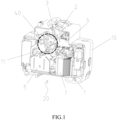
FIG. 3 is a schematic view of a double-breakpoint test mechanism in the open state of the circuit breaker according to embodiments; -
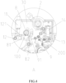
FIG. 4 is a partially enlarged view at part A inFIG. 3 ; -
FIG. 5 is a schematic view of the double-breakpoint test mechanism in a closed state of the circuit breaker according to embodiments; -
FIG. 6 is a partially enlarged view at part B inFIG. 5 ; -
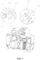
FIG. 7 is a perspective schematic view of the circuit breaker in the closed state according to embodiments (part of the base being omitted to show an internal structure of the leakage protection unit); -
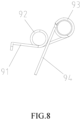
FIG. 8 is a schematic view of a second elastic member according to embodiments. - To further elaborate various embodiments, the present disclosure provides accompanying drawings. These accompanying drawings are part of the present disclosure and are mainly used to illustrate the embodiments, and may be combined with relevant descriptions in the specification to explain operation principles of the embodiments. With reference to these contents, a person skilled in the art should understand other possible embodiments and advantages of the present disclosure. Components in the drawings are not drawn to scale, and similar component symbols are generally used to denote similar components.
- The present disclosure will be further described in connection with the accompanying drawings and specific embodiments.
- As shown in
FIGS. 1-2 , as a preferred embodiment of the present disclosure, a circuit breaker, more specifically a residual current protection circuit breaker, is provided, including acircuit breaker unit 10 and aleakage protection unit 20 that are connected in parallel with their poles. Thecircuit breaker unit 10 is used to achieve functions such as circuit turn-on and turn-off, overload protection, and short-circuit protection. Theleakage protection unit 20 is used to detect a leakage current in a circuit and push thecircuit breaker unit 10 to open under an action of a tripping mechanism (releasing mechanism) 40, thereby protecting personal safety. Theleakage protection unit 20 specifically includes a base 1, ahandle 2, aconnection rod 3, thetripping mechanism 40, anelectromagnetic release 5, a control circuit board 6, and a zero-sequence current transformer 7. The base 1 includes apartition plate 30 configured to separate a L-pole circuit from a N-pole circuit in thecircuit breaker unit 10. Thetripping mechanism 40 includes a tripping member (releasing member) 41, a tripping latch (releasing latch) 42, alock latch 43, and areset member 44. Thehandle 2, thetripping member 41, thelock latch 43, and thereset member 44 are all rotatably and pivotally connected to the base 1, and thetripping latch 42 is pivotally connected to thetripping member 41. Thehandle 2 is linked and connected with thetripping latch 42 through theconnection rod 3. Thelock latch 43 is provided with a curved-hook-shaped locking portion (not labeled in the figures). Thetripping latch 42 is provided with a curved-hook-shaped locked portion (not labeled in the figures) that can be buckled with the locking portion. - In an open state of the circuit breaker, the
handle 2 is toggled and drives thetripping latch 42 rotate through linkage of theconnection rod 3, until the locked portion and the locking portion are buckled due to rotation of the tripping latch. At this time, the lock latch forms a limit on the tripping latch, and the locking portion provides a fulcrum for thetripping latch 42. Under a continuous force of thehandle 2, thetripping latch 42 rotates together with thetripping member 41. Thetripping member 41 includes a linkage connection portion that extends into thecircuit breaker unit 10. Thelinkage connection portion 41 cooperates with an operating mechanism of thecircuit breaker unit 10 to toggle thecircuit breaker unit 10 to open when theleakage protection unit 20 is opened. - A main circuit of the
circuit breaker unit 10 passes through the zero-sequence current transformer 7, and the zero-sequence current transformer 7 is configured to detect the leakage current in the circuit. When the zero-sequencecurrent transformer 7 detects the leakage current, a signal is fed back to the control circuit board 6. After setting the signal, the control circuit board 6 sends out a command to make theelectromagnetic release 5 act. Thereset member 44 is disposed at a side of theelectromagnetic release 5, and when an output rod of theelectromagnetic release 5 extends, thereset member 44 can be pushed to rotate. Meanwhile, thereset member 44 is linked with thelock latch 43. After receiving the push of the output rod of theelectromagnetic release 5, thereset member 44 can be pushed against and act on thelock latch 43, thereby toggling thelock latch 43 to rotate, and unlocking the locked portion and the locking portion. After the locked portion and the locking portion are unbuckled, the trippingmechanism 40 quickly trips and opens, and the trippingmember 41 rotates and cooperates with the operating mechanism of thecircuit breaker unit 10 to achieve tripping and opening of theleakage protection unit 20 and thecircuit breaker unit 10. - The above structure of the tripping
mechanism 40 can refer to inventors' patent applicationCN114883154A . - A first
elastic member 8 and a secondelastic member 9 are installed on the base 1 and configured to provide a first reset force and a second reset force for the trippingmember 41 and thelock latch 43, respectively, thereby achieving rotational resetting of the trippingmember 41 and thelock latch 43. The firstelastic member 8 and the secondelastic member 9 also serve as part of a double-breakpoint test mechanism of the circuit breaker, to achieve conduction of a test circuit. As shown inFIGS. 4 ,6 and7 , the double-breakpoint test mechanism includes atest button 11, atest torsion spring 12, and atest resistor 14. Thetest button 11 is slidably installed on the base 1, and an outer end of thetest button 11 is exposed out of the base 1. The base 1 is provided with a torsion spring shaft, and a helical portion of thetest torsion spring 12 is socketed to the torsion spring shaft arranged on the base 1. Thetest torsion spring 12 also includes a first torsion arm and asecond torsion arm 121. The first torsion arm of thetest torsion spring 12 is connected to the test circuit, and thesecond torsion arm 121 is oppositely arranged at an inner end side of thebutton 11. Thetest resistor 14 and thetest button 11 are spaced apart, and the firstelastic member 8 and the secondelastic member 9 are arranged between thetest resistor 14 and thetest button 11. In this embodiment, both the firstelastic member 8 and the secondelastic member 9 are torsion springs. The base 1 is provided with two torsion spring shafts as afirst assembly site 100 and asecond assembly site 200, and the firstelastic member 8 and the secondelastic member 9 are installed on the two torsion spring shafts of thefirst assembly site 100 and thesecond assembly site 200, respectively. The firstelastic member 8 includes athird torsion arm 81 and afourth torsion arm 82; thethird torsion arm 81 is fixedly connected to the base 1; and thethird torsion arm 81 is arranged close to thesecond torsion arm 121. When thetest button 11 is pressed, thetest button 11 can push thesecond torsion arm 121 of thetest torsion spring 12 downwards, and hence thesecond torsion arm 121 has a first motion stroke. Thethird torsion arm 81 of the firstelastic member 8 is arranged within a stroke range of the first motion stroke, so that thetest button 11 can push thesecond torsion arm 121 of thetest torsion spring 12 into lapping contact with thethird torsion arm 81 of the firstelastic member 8 to achieve conduction. When thetest button 11 is not pressed, thethird torsion arm 81 and thesecond torsion arm 121 are disconnected, thereby forming a first breakpoint of the test circuit. Thefourth torsion arm 82 as a reset end of the firstelastic member 8 acts on the trippingmember 41 to provide the first reset force for the trippingmember 41. Specifically, thefourth torsion arm 82 may be fixedly connected to the trippingmember 41 or may abut against the trippingmember 41. When the tripping member 41rotating, the trippingmember 41 also pushes thefourth torsion arm 82 to swing, and hence thefourth torsion arm 82 has a second motion stroke. The secondelastic member 9 includes afifth torsion arm 91 arranged within a stroke range of the second motion stroke of thefourth torsion arm 82. The trippingmember 41 is linked and connected with the operating mechanism of the circuit breaker unit 1. When the circuit breaker is closed, the trippingmember 41 rotates and can bring thefourth torsion arm 82 into lapping contact with thefifth torsion arm 91 to achieve conduction. When the circuit breaker is opened, thefourth torsion arm 82 and thefifth torsion arm 91 are disconnected, thereby forming a second breakpoint of the test circuit. - A third
elastic member 13 is also provided between the secondelastic member 9 and thetest resistor 14, and in this embodiment, the thirdelastic member 13 is also a torsion spring. One of torsion arms of the thirdelastic member 13 maintains electrical contact with the secondelastic member 9 through elastic force, while the other torsion arm of the thirdelastic member 13 maintains electrical contact with one end of thetest resistor 14 through elastic force; and another end of thetest resistor 14 is connected to the test circuit. Specifically, in this embodiment, the first torsion arm of thetest torsion spring 12 is electrically connected to an arc plate of an N pole of thecircuit breaker unit 10; another end of thetest resistor 14 is soldered to a signal wire, and in turn the signal wire is soldered to a wiring portion of a L pole of thecircuit breaker unit 10. In such a way, the test circuit can connect the N pole and the L pole to detect the leakage current after the first breakpoint and the second breakpoint are connected. The thirdelastic member 13 is not necessary; in other embodiments, another torsion arm (not the fifth torsion arm 91) may extend from the secondelastic member 9, and is fixedly connected to the base 1 while extending to the one end of thetest resistor 14 to be electrically connected to thetest resistor 14. However, in this way, the electrical connection between the secondelastic member 9 and thetest resistor 14 may not be reliable. In this embodiment, the thirdelastic member 13 is provided, which can reliably make electrical contact with the secondelastic member 9 and thetest resistor 14 by utilizing elastic compression force of two torsion arms of the thirdelastic member 13, to ensure reliable conduction of the test circuit. - The test circuit in this embodiment forms a double-breakpoint design, and the second breakpoint is only connected when the circuit breaker is closed, which improves safety performance. Most importantly, this embodiment forms the test circuit by utilizing the first
elastic member 8 and the secondelastic member 9 already relevant in the original trippingmechanism 40, so that the components are highly integrated without need for additional conductive components, the structure is simple, and the cost is low. - In this embodiment, the
test button 11 is at a left side of thetest resistor 14, and thetest resistor 14 is at a right side of thetest button 11; thetest button 11 is close to a left end housing of the base 1, and thetest resistor 14 is close to a right end housing of the base 1. As a result, a spacing width between thetest resistor 14 and thetest button 11 is maximized to provide sufficient space for arranging the firstelastic member 8, the secondelastic member 9, and a connection spring 13 (i.e. third elastic member 13). The firstelastic member 8, the secondelastic member 9, and theconnection spring 13 are arranged in sequence from left to right. In this embodiment, the secondelastic member 9 is a double-torsion spring (a twin-torsion spring), and such arrangement allows the secondelastic member 9 to have a large span over a range of the spacing width between thetest resistor 14 and thetest button 11, which facilitates the connection of the secondelastic member 9 with the firstelastic member 8 and the thirdelastic member 13, and this structure also facilitates installation. As shown inFIGS. 4 and8 , the secondelastic member 9 specifically includes a firsthelical portion 92, a secondhelical portion 93, afifth torsion arm 91, and asixth torsion arm 94. The firsthelical portion 92 is closer to thetest button 11 than the secondhelical portion 93. Thefifth torsion arm 91 extends from the firsthelical portion 92, and thesixth torsion arm 94 extends from the secondhelical portion 93. Thesixth torsion arm 94 abuts against thelock latch 43 by its own elastic force, to reset thelock latch 43. One torsion arm of the thirdelastic member 13 abuts against the secondhelical portion 93 through elastic force. - In this embodiment, respective torsion spring shafts used for installing the
test torsion spring 12, the firstelastic member 8, and the secondelastic member 9 are all protruding in a direction perpendicular to thepartition plate 30. Thesecond torsion arm 121 includes a first contact portion parallel to thepartition plate 30, and thethird torsion arm 81 includes a second contact portion perpendicular to thepartition plate 30, so that the first contact portion of thesecond torsion arm 121 and the second contact portion of thethird torsion arm 81 are perpendicularly opposed to each other, improving the contact reliability of lapping conduction between thesecond torsion arm 121 and thethird torsion arm 81. Similarly, thefourth torsion arm 82 and thefifth torsion arm 91 are designed in the same way that their contact portions are perpendicularly opposed to each other. That is, thefourth torsion arm 82 may be provided with a third contact portion, and thefifth torsion arm 91 may be provided with a fourth contact portion corresponding to the third contact portion, in which the third contact portion and the fourth contact portion are perpendicularly opposed to each other. Any group of two opposing contact portions described above may also be staggered at an angle not equal to 90° in other embodiments. - In other embodiments, the first
elastic member 8, the secondelastic member 9, and the thirdelastic member 13 may also be implemented using other elastic member structures, such as a clockwork, an elastic piece, a cylindrical spring, or a combination structure of an elastic piece and a cylindrical spring. In order to achieve the same function as the firstelastic member 8, the secondelastic member 9, and the thirdelastic member 13 in this embodiment, it is obviously attainable for the person skilled in the art to make adaptive substitutions using similar elastic member structures. As commonly used rotating reset members, the firstelastic member 8 and the secondelastic member 9, which adopt torsion spring structures, can be quickly upgraded based on the original trippingmechanism 40 without complex structural modifications. Overall, only installation sites of the torsion springs and positions of the torsion arms need to be adjusted. Moreover, the firstelastic member 8, the secondelastic member 9, and the thirdelastic member 13 all adopt torsion spring structures, which can facilitate product assembly and save installation space.
Claims (9)
- A double-breakpoint test mechanism applied to a circuit breaker, comprising a test button (11) and a test torsion spring (12), characterized in that the double-breakpoint test mechanism further comprises:a first elastic member (8) and a second elastic member (9), which are configured to provide a reset force and perform contact conduction,the first elastic member (8) and the second elastic member (9) are assembled in a first assembly site (100) and a second assembly site (200) respectively to provide a first reset force and a second reset force for a tripping mechanism (40) of the circuit breaker; andwhen the first elastic member (8) and the second elastic member (9) are in the first assembly site (100) and the second assembly site (200) respectively, a first breakpoint is formed between the test torsion spring (12) and the first elastic member (8), and a second breakpoint is formed between the first elastic member (8) and the second elastic member (9);the first elastic member (8) comprises a first end close to the test torsion spring (12) and a second end close to the second elastic member (9);the test torsion spring (12) is pushed by the test button (11) to have a first motion stroke, and the first end of the first elastic member (8) is arranged within a stroke range of the first motion stroke, allowing the test button (11) to push the test torsion spring (12) into contact conduction with the first end of the first elastic member (8); andwhen the circuit breaker is closed, the second end of the first elastic member (8) is pushed by the tripping mechanism (40) to have a second motion stroke, and the second elastic member (9) is arranged within a stroke range of the second motion stroke, allowing the tripping member to push the second end of the first elastic member (8) into contact conduction with the second elastic member (9) when the circuit breaker is closed.
- The double-breakpoint test mechanism applied to a circuit breaker according to claim 1, characterized in that both the first elastic member (8) and the second elastic member (9) are torsion springs; two torsion arms of the first elastic member (8) serve as the first end and the second end; one torsion arm of the second elastic member (9) is arranged within the stroke range of the second motion stroke.
- The double-breakpoint test mechanism applied to a circuit breaker according to claim 1 or 2, characterized in that the double-breakpoint test mechanism further comprises:a test resistor (14); anda third elastic member (13), one end of the third elastic member (13) keeps contact conduction with the second elastic member (9) through elastic force, and another end of the third elastic member (13) keeps contact conduction with the test resistor (14) through elastic force.
- The double-breakpoint test mechanism applied to a circuit breaker according to claim 3, characterized in that the test button (11) and the test resistor (14) are spaced apart, and the first elastic member (8), the second elastic member (9) and the third elastic member (13) are sequentially arranged between the test button (11) and the test resistor (14).
- The double-breakpoint test mechanism applied to a circuit breaker according to claim 3 or 4, characterized in that the second elastic member (9) is a double-torsion spring and comprises a first helical portion (92) and a second helical portion (93), the first helical portion (92) being closer to the test button (11) than the second helical portion (93).
- The double-breakpoint test mechanism applied to a circuit breaker according to any one of the preceding claims, characterized in that the test torsion spring (12) comprises a first contact portion configured to contact the first elastic member (8), and the first elastic member (8) comprises a second contact portion corresponding to the first contact portion, the first contact portion and the second contact portion being staggered opposite to each other; and/or
the first elastic member (8) comprises a third contact portion configured to contact the second elastic member (9), and the second elastic member (9) comprises a fourth contact portion corresponding to the third contact portion, the third contact portion and the fourth contact portion being staggered opposite to each other. - A circuit breaker, comprising a circuit breaker unit (10) and a leakage protection unit (20), and the leakage protection unit (20) comprising a tripping mechanism (40) and a test mechanism,characterized in that the test mechanism is the double-breakpoint test mechanism according to any one of the preceding claims; andthe circuit breaker further comprises a first assembly site (100) and a second assembly site (200), the first elastic member (8) and the second elastic member (9) being assembled in the first assembly site (100) and the second assembly site (200) respectively to provide a first reset force and a second reset force for the tripping mechanism (40).
- The circuit breaker according to claim 7, characterized in that the circuit breaker further comprises a base (1), and the tripping mechanism (40) comprises a tripping member (41), a tripping latch (42), a lock latch (43), and a reset member (44); the tripping member (41), the lock latch (43), and the reset member (44) are pivotally connected to the base (1); the tripping latch (42) is pivotally connected to the tripping member (41); and the first elastic member (8) and the second elastic member (9) are rotating reset members (44) for the tripping member (41) and the lock latch (43) respectively.
- The circuit breaker according to claim 7, characterized in that the circuit breaker further comprises a base (1),the test mechanism further comprises a third elastic member (13) and a test resistor (14); one end of the third elastic member (13) keeps contact conduction with the second elastic member (9) through elastic force, and another end of the third elastic member (13) keeps contact conduction with the test resistor (14) through elastic force;the test button (11) and the test resistor (14) are spaced apart, the test button (11) being at a left side of the test resistor (14), the test resistor (14) being at a right side of the test button (11);the test button (11) is close to a left end housing of the base (1), and the test resistor (14) is close to a right end housing of the base (1); andthe first elastic member (8) and the second elastic member (9) are arranged in sequence from left to right between the test button (11) and the test resistor (14).
Applications Claiming Priority (1)
| Application Number | Priority Date | Filing Date | Title |
|---|---|---|---|
| CN202311427728.8A CN117406080A (en) | 2023-10-31 | 2023-10-31 | Double breakpoint testing mechanism and circuit breakers used in circuit breakers |
Publications (3)
| Publication Number | Publication Date |
|---|---|
| EP4550381A1 true EP4550381A1 (en) | 2025-05-07 |
| EP4550381B1 EP4550381B1 (en) | 2025-10-22 |
| EP4550381C0 EP4550381C0 (en) | 2025-10-22 |
Family
ID=89494082
Family Applications (1)
| Application Number | Title | Priority Date | Filing Date |
|---|---|---|---|
| EP24209966.1A Active EP4550381B1 (en) | 2023-10-31 | 2024-10-30 | Double-breakpoint test mechanism applied to circuit breaker and circuit breaker |
Country Status (3)
| Country | Link |
|---|---|
| EP (1) | EP4550381B1 (en) |
| CN (1) | CN117406080A (en) |
| PL (1) | PL4550381T3 (en) |
Citations (6)
| Publication number | Priority date | Publication date | Assignee | Title |
|---|---|---|---|---|
| EP0320929A2 (en) * | 1987-12-17 | 1989-06-21 | ABB Elettrocondutture S.p.A. | Device for releasing the contacts of differential switches |
| EP0231732B1 (en) * | 1985-12-02 | 1990-07-18 | Felten & Guilleaume Fabrik elektrischer Apparate Aktiengesellschaft | Circuit breaker for fault and conduction current protection |
| EP0914666B1 (en) * | 1997-05-20 | 2005-06-22 | GEWISS S.p.A. | Kinematic system for actuating the movable contact of automatic electric breakers |
| CN209981152U (en) * | 2019-06-25 | 2020-01-21 | 浙江正泰电器股份有限公司 | Residual current operated circuit breaker |
| CN110739194A (en) * | 2019-11-29 | 2020-01-31 | 加西亚电子电器股份有限公司 | Circuit breaker test device and circuit breaker with the same |
| CN114883154A (en) | 2022-05-27 | 2022-08-09 | 厦门宏发开关设备有限公司 | Leakage protection unit and residual current protection circuit breaker |
Family Cites Families (3)
| Publication number | Priority date | Publication date | Assignee | Title |
|---|---|---|---|---|
| CN216646758U (en) * | 2021-12-31 | 2022-05-31 | 北京北元电器有限公司 | Testing device mounted on residual-current circuit breaker |
| CN116794495A (en) * | 2022-03-18 | 2023-09-22 | 厦门宏发开关设备有限公司 | a circuit breaker |
| CN221746236U (en) * | 2023-10-31 | 2024-09-20 | 厦门宏发汽车电子有限公司 | Double breakpoint test mechanism and circuit breaker used in circuit breakers |
-
2023
- 2023-10-31 CN CN202311427728.8A patent/CN117406080A/en active Pending
-
2024
- 2024-10-30 EP EP24209966.1A patent/EP4550381B1/en active Active
- 2024-10-30 PL PL24209966.1T patent/PL4550381T3/en unknown
Patent Citations (6)
| Publication number | Priority date | Publication date | Assignee | Title |
|---|---|---|---|---|
| EP0231732B1 (en) * | 1985-12-02 | 1990-07-18 | Felten & Guilleaume Fabrik elektrischer Apparate Aktiengesellschaft | Circuit breaker for fault and conduction current protection |
| EP0320929A2 (en) * | 1987-12-17 | 1989-06-21 | ABB Elettrocondutture S.p.A. | Device for releasing the contacts of differential switches |
| EP0914666B1 (en) * | 1997-05-20 | 2005-06-22 | GEWISS S.p.A. | Kinematic system for actuating the movable contact of automatic electric breakers |
| CN209981152U (en) * | 2019-06-25 | 2020-01-21 | 浙江正泰电器股份有限公司 | Residual current operated circuit breaker |
| CN110739194A (en) * | 2019-11-29 | 2020-01-31 | 加西亚电子电器股份有限公司 | Circuit breaker test device and circuit breaker with the same |
| CN114883154A (en) | 2022-05-27 | 2022-08-09 | 厦门宏发开关设备有限公司 | Leakage protection unit and residual current protection circuit breaker |
Also Published As
| Publication number | Publication date |
|---|---|
| EP4550381B1 (en) | 2025-10-22 |
| EP4550381C0 (en) | 2025-10-22 |
| CN117406080A (en) | 2024-01-16 |
| PL4550381T3 (en) | 2025-12-15 |
Similar Documents
| Publication | Publication Date | Title |
|---|---|---|
| CN109585233B (en) | Small-sized circuit breaker | |
| CN111341612B (en) | breaker | |
| AU2019386913B2 (en) | Circuit breaker | |
| CN109659203B (en) | A small circuit breaker abnormal protection device and a small circuit breaker | |
| EP4318519A1 (en) | Test button loop device and circuit breaker | |
| EP4597537A1 (en) | Tripping mechanism of circuit breaker, and circuit breaker | |
| CA2316488C (en) | Circuit interrupter with non-symmetrical terminal collar | |
| EP4550381B1 (en) | Double-breakpoint test mechanism applied to circuit breaker and circuit breaker | |
| CN221746236U (en) | Double breakpoint test mechanism and circuit breaker used in circuit breakers | |
| CN118737769B (en) | Operating device of leakage protection circuit breaker | |
| CN120581414A (en) | Electromagnetic leakage circuit breaker | |
| JPH04229525A (en) | Multicircuit breaker | |
| CN217061822U (en) | Test button loop device and circuit breaker | |
| CN121601506A (en) | Leakage protection circuit breaker | |
| CN115602502B (en) | Tripping structure of circuit breaker | |
| CN117116717A (en) | Circuit breaker with leakage protection | |
| CN209401580U (en) | Miniature circuit breaker abnormal protection device and miniature circuit breaker | |
| CN115472471A (en) | A circuit breaker and combined switching device | |
| CN222672935U (en) | Leakage protection circuit breaker | |
| CN222867584U (en) | Leakage protection circuit breaker | |
| CN223927331U (en) | Small-sized breaker operating mechanism | |
| CN222914702U (en) | Phase pole and neutral pole type residual current operated circuit breaker | |
| CN209981152U (en) | Residual current operated circuit breaker | |
| CN121075867A (en) | Leakage protection circuit breaker | |
| CN221805418U (en) | A circuit breaker |
Legal Events
| Date | Code | Title | Description |
|---|---|---|---|
| PUAI | Public reference made under article 153(3) epc to a published international application that has entered the european phase |
Free format text: ORIGINAL CODE: 0009012 |
|
| STAA | Information on the status of an ep patent application or granted ep patent |
Free format text: STATUS: REQUEST FOR EXAMINATION WAS MADE |
|
| 17P | Request for examination filed |
Effective date: 20241030 |
|
| AK | Designated contracting states |
Kind code of ref document: A1 Designated state(s): AL AT BE BG CH CY CZ DE DK EE ES FI FR GB GR HR HU IE IS IT LI LT LU LV MC ME MK MT NL NO PL PT RO RS SE SI SK SM TR |
|
| GRAP | Despatch of communication of intention to grant a patent |
Free format text: ORIGINAL CODE: EPIDOSNIGR1 |
|
| STAA | Information on the status of an ep patent application or granted ep patent |
Free format text: STATUS: GRANT OF PATENT IS INTENDED |
|
| RIC1 | Information provided on ipc code assigned before grant |
Ipc: H01H 71/12 20060101ALN20250604BHEP Ipc: H01H 83/04 20060101AFI20250604BHEP |
|
| INTG | Intention to grant announced |
Effective date: 20250616 |
|
| GRAS | Grant fee paid |
Free format text: ORIGINAL CODE: EPIDOSNIGR3 |
|
| GRAA | (expected) grant |
Free format text: ORIGINAL CODE: 0009210 |
|
| STAA | Information on the status of an ep patent application or granted ep patent |
Free format text: STATUS: THE PATENT HAS BEEN GRANTED |
|
| AK | Designated contracting states |
Kind code of ref document: B1 Designated state(s): AL AT BE BG CH CY CZ DE DK EE ES FI FR GB GR HR HU IE IS IT LI LT LU LV MC ME MK MT NL NO PL PT RO RS SE SI SK SM TR |
|
| REG | Reference to a national code |
Ref country code: CH Ref legal event code: F10 Free format text: ST27 STATUS EVENT CODE: U-0-0-F10-F00 (AS PROVIDED BY THE NATIONAL OFFICE) Effective date: 20251022 Ref country code: GB Ref legal event code: FG4D |
|
| REG | Reference to a national code |
Ref country code: DE Ref legal event code: R096 Ref document number: 602024001017 Country of ref document: DE |
|
| REG | Reference to a national code |
Ref country code: IE Ref legal event code: FG4D |
|
| U01 | Request for unitary effect filed |
Effective date: 20251119 |
|
| U07 | Unitary effect registered |
Designated state(s): AT BE BG DE DK EE FI FR IT LT LU LV MT NL PT RO SE SI Effective date: 20251125 |
|
| U20 | Renewal fee for the european patent with unitary effect paid |
Year of fee payment: 2 Effective date: 20251216 |
|
| PGFP | Annual fee paid to national office [announced via postgrant information from national office to epo] |
Ref country code: PL Payment date: 20251215 Year of fee payment: 2 |
|
| PG25 | Lapsed in a contracting state [announced via postgrant information from national office to epo] |
Ref country code: ES Free format text: LAPSE BECAUSE OF FAILURE TO SUBMIT A TRANSLATION OF THE DESCRIPTION OR TO PAY THE FEE WITHIN THE PRESCRIBED TIME-LIMIT Effective date: 20251022 |
|
| PG25 | Lapsed in a contracting state [announced via postgrant information from national office to epo] |
Ref country code: NO Free format text: LAPSE BECAUSE OF FAILURE TO SUBMIT A TRANSLATION OF THE DESCRIPTION OR TO PAY THE FEE WITHIN THE PRESCRIBED TIME-LIMIT Effective date: 20260122 |
|
| PG25 | Lapsed in a contracting state [announced via postgrant information from national office to epo] |
Ref country code: HR Free format text: LAPSE BECAUSE OF FAILURE TO SUBMIT A TRANSLATION OF THE DESCRIPTION OR TO PAY THE FEE WITHIN THE PRESCRIBED TIME-LIMIT Effective date: 20251022 |
|
| PG25 | Lapsed in a contracting state [announced via postgrant information from national office to epo] |
Ref country code: RS Free format text: LAPSE BECAUSE OF FAILURE TO SUBMIT A TRANSLATION OF THE DESCRIPTION OR TO PAY THE FEE WITHIN THE PRESCRIBED TIME-LIMIT Effective date: 20260122 |
|
| PG25 | Lapsed in a contracting state [announced via postgrant information from national office to epo] |
Ref country code: IS Free format text: LAPSE BECAUSE OF FAILURE TO SUBMIT A TRANSLATION OF THE DESCRIPTION OR TO PAY THE FEE WITHIN THE PRESCRIBED TIME-LIMIT Effective date: 20260222 |
|
| PG25 | Lapsed in a contracting state [announced via postgrant information from national office to epo] |
Ref country code: SM Free format text: LAPSE BECAUSE OF FAILURE TO SUBMIT A TRANSLATION OF THE DESCRIPTION OR TO PAY THE FEE WITHIN THE PRESCRIBED TIME-LIMIT Effective date: 20251022 |
|
| PG25 | Lapsed in a contracting state [announced via postgrant information from national office to epo] |
Ref country code: MC Free format text: LAPSE BECAUSE OF FAILURE TO SUBMIT A TRANSLATION OF THE DESCRIPTION OR TO PAY THE FEE WITHIN THE PRESCRIBED TIME-LIMIT Effective date: 20251022 |
|
| PG25 | Lapsed in a contracting state [announced via postgrant information from national office to epo] |
Ref country code: CZ Free format text: LAPSE BECAUSE OF FAILURE TO SUBMIT A TRANSLATION OF THE DESCRIPTION OR TO PAY THE FEE WITHIN THE PRESCRIBED TIME-LIMIT Effective date: 20251022 |
|
| PG25 | Lapsed in a contracting state [announced via postgrant information from national office to epo] |
Ref country code: SK Free format text: LAPSE BECAUSE OF FAILURE TO SUBMIT A TRANSLATION OF THE DESCRIPTION OR TO PAY THE FEE WITHIN THE PRESCRIBED TIME-LIMIT Effective date: 20251022 |