EP4550379A1 - Circuit-breaker with a nozzle structure - Google Patents
Circuit-breaker with a nozzle structure Download PDFInfo
- Publication number
- EP4550379A1 EP4550379A1 EP23206804.9A EP23206804A EP4550379A1 EP 4550379 A1 EP4550379 A1 EP 4550379A1 EP 23206804 A EP23206804 A EP 23206804A EP 4550379 A1 EP4550379 A1 EP 4550379A1
- Authority
- EP
- European Patent Office
- Prior art keywords
- contact
- arcing
- auxiliary
- nozzle
- breaker
- Prior art date
- Legal status (The legal status is an assumption and is not a legal conclusion. Google has not performed a legal analysis and makes no representation as to the accuracy of the status listed.)
- Pending
Links
Images

Classifications
-
- H—ELECTRICITY
- H01—ELECTRIC ELEMENTS
- H01H—ELECTRIC SWITCHES; RELAYS; SELECTORS; EMERGENCY PROTECTIVE DEVICES
- H01H33/00—High-tension or heavy-current switches with arc-extinguishing or arc-preventing means
- H01H33/70—Switches with separate means for directing, obtaining, or increasing flow of arc-extinguishing fluid
- H01H33/72—Switches with separate means for directing, obtaining, or increasing flow of arc-extinguishing fluid having stationary parts for directing the flow of arc-extinguishing fluid, e.g. arc-extinguishing chamber
- H01H33/74—Switches with separate means for directing, obtaining, or increasing flow of arc-extinguishing fluid having stationary parts for directing the flow of arc-extinguishing fluid, e.g. arc-extinguishing chamber wherein the break is in gas
-
- H—ELECTRICITY
- H01—ELECTRIC ELEMENTS
- H01H—ELECTRIC SWITCHES; RELAYS; SELECTORS; EMERGENCY PROTECTIVE DEVICES
- H01H33/00—High-tension or heavy-current switches with arc-extinguishing or arc-preventing means
- H01H33/70—Switches with separate means for directing, obtaining, or increasing flow of arc-extinguishing fluid
- H01H33/76—Switches with separate means for directing, obtaining, or increasing flow of arc-extinguishing fluid wherein arc-extinguishing gas is evolved from stationary parts; Selection of material therefor
Definitions
- the invention relates to a circuit-breaker, especially for high-voltage applications.
- the circuit-breaker comprises a first and a second contact structure and a nozzle structure.
- the circuit-breaker is configured to make or break an electrical connection between the first and second contact structures.
- arcing upon operating a circuit-breaker e.g. making or breaking current and/or an electrical connection, especially at high voltages, results in wear of contact structures and of a nozzle structure of a circuit-breaker. Further, it has been found that electrical fields within a circuit-breaker may affect the arcing location or duration.
- circuit-breaker for high-voltage applications
- the present invention suggests a high-voltage circuit-breaker which has contact elements that can form or withstand an arc upon operating the breaker (e.g. making or breaking the current), wherein the arc is to be located in an arcing area in front of the first contact element.
- a nozzle arranged substantially around the first contact element and with a duct is provided, which duct is in connection with the arcing area.
- One or both of the contact elements can be moved along an axis for switching of the breaker.
- a further contact element is provided that is coupled with the first contact element and that runs, e.g. radially away from the first contact element, within the duct so that an arc coming from the arcing area can be directed towards the further contact element. This helps in arc quenching and size reduction.
- the invention is facing and giving a solution for the problem that a space for the arc is typically limited by the size of the arcing contacts and the nozzle structure.
- High currents may need more surface of the nozzle and more surface of the arcing contacts, i.e. may be in contact with those on a greater surface area and/or may produce more wear on those. Constructing the circuit-breaker with respect to high currents therefore requires bigger arcing contacts and a bigger nozzle structure, which increases size and/or costs of the circuit-breaker.
- the auxiliary contact is proposed.
- the proposed solution is based on the idea that an arc or discharge coming from the arcing zone can get into the auxiliary channel in the nozzle structure and shall be received by a certain contact that has the potential of the first arcing contact.
- the auxiliary channel may support arc extinguishment.
- the invention helps to not necessarily increase a size of the circuit-breaker although making it compatible for higher currents.
- a size of the circuit-breaker may be reduced by way of the auxiliary contact while still being capable of the same height of currents.
- arc extinguishment is improved by way of utilizing the auxiliary channel in this respect.
- the nozzle structure and therewith the circuit-breaker has a longer lifetime. There may be less material damage occurring in the nozzle structure since the arcs may be directed to the auxiliary contact, if coming from the arcing zone through the auxiliary channel.
- the circuit-breaker can make or break an electrical connection.
- the circuit-breaker may have or may be configured as an interrupter.
- the circuit-breaker may have a gas damper.
- the circuit-breaker may have a drive device.
- the gas damper and/or the drive device may be coupled with the first contact structure and/or the second contact structure.
- the circuit-breaker may have a housing for the contact structures and the nozzle structure.
- the housing may comprise a volume, especially filled with gas or fluid e.g. an insulating gas and/or dielectric gas or fluid.
- the housing is preferably provided gas-tight and/or comprises a tube-like or cylinder-like form extending along the switching axis.
- the drive device is preferably motorized and/or provided outside of the housing. In such implementation the drive device can be connected to the first contact structure or the second contact structure, especially via a pull rod.
- the drive device may comprise an additional damper, which can be associated and/or integrated to the drive device.
- the first and/or second contact structure typically relates to an assembly and/or means for an electrical connection.
- the first and/or second contact structure is typically at least partially and/or sectionally electrically conductive.
- the first and/or second contact structure may have at least one contact.
- the first and/or second contact structure has an arcing contact and particularly a nominal contact.
- the arcing contact is meant for withstanding arcs during opening or closing of the circuit-breaker.
- the nominal contact is meant for nominal current conduction when the circuit-breaker is closed.
- the first and/or second contact structure may be formed at least substantially cylindrical and/or round.
- the first contact structure has a first nominal contact especially arranged radially outside the nozzle structure and/or the first arcing contact.
- the nozzle structure may be arranged between the first nominal contact and the first arcing contact.
- the second contact structure includes a second nominal contact corresponding to the first nominal contact.
- nominal contacts high electrical currents can be conducted.
- One or both of the nominal contacts, especially the second nominal contact may have and/or be covered by a shield, particularly dielectric shield to shield the contact electrically.
- the dielectric shield is not necessarily insulating.
- the dielectric shield may be dielectric and/or made of metal for guiding or controlling the electrical field, especially for shielding the nominal contact(s) from electrical fields.
- the first contact structure may have a first arcing contact and particularly a nozzle structure.
- the nozzle structure is particularly configured to surround and/or enclose the first arcing contact, particularly around the switching axis.
- the first arcing contact is typically at least sectionally or partially made of metal.
- the first arcing contact may comprise or consist of tungsten, copper gold and/or silver.
- the first arcing contact may have a tulip shape, particularly extending at least partially or sectionally along the switching axis.
- the nozzle structure may have a channel or auxiliary channel.
- the auxiliary channel particularly leads to an arcing zone preferably adjacent to the first arcing contact.
- the arcing zone is typically arranged in front of the first arcing contact and/or between the arcing contacts, for example along the switching axis.
- the auxiliary channel particularly connects the arcing zone with a heating volume for receiving heated gas or fluid coming from the arcing zone.
- the auxiliary channel may be referred to as a heating channel since it connects the heating volume with the arc zone and/or since it may guide heated gas or fluid away from the arcing zone.
- the arc zone may be referred to as a main channel for the arc to occur, to which main channel the auxiliary channel or heating channel is typically connected.
- the nozzle structure is typically, at least sectionally or partially, and preferably at least in the section forming the auxiliary channel and/or in a section forming the arcing zone, made of a polymer compound, especially a thermoplastic polymer compound, e.g. Polytetrafluoroethylene, PTFE for short.
- the nozzle structure may be formed at least substantially annular, particularly around the switching axis.
- the nozzle structure is typically configured for arc quenching and/or for guiding a fluid or a gas from or to the arcing zone. Also, the nozzle structure is typically configured for surrounding an arc established between the contact structures.
- the nozzle structure may have a main nozzle and/or an auxiliary nozzle.
- the main nozzle and/or the auxiliary nozzle may surround the first arcing contact and/or may have an/the annular shape.
- the auxiliary nozzle may be inserted into the main nozzle, particularly along the switching axis and/or a first direction.
- the nozzle structure, particularly the main nozzle may form a part of the auxiliary channel particularly leading to the arcing zone.
- the nozzle structure may include a main nozzle throat and particularly an auxiliary nozzle throat.
- the main nozzle throat and particularly the auxiliary nozzle throat may constrict an/the arcing zone.
- the main nozzle throat and particularly the auxiliary nozzle throat may comprise an annular and/or cylindrical inner surface.
- the main nozzle throat and/or the auxiliary nozzle throat may have a diameter of at least 10 mm or at least 20 mm and/or of up to 40 mm or up to 50 mm; for example, the diameter may be 30 ⁇ 10 mm for sufficient arc extinguishing properties.
- the main nozzle throat and the auxiliary nozzle throat may be in diameter at least substantially of the same size, i.e.
- the main nozzle throat may be at least 0,5 mm, 1 mm, 2 mm or more, and may be up to 1 mm, 2 mm, 3 mm or more larger than the auxiliary nozzle throat.
- the auxiliary channel may be arranged at least sectionally between the main nozzle throat and the auxiliary nozzle throat. Particularly, the auxiliary channel may point/run in a radially outwards direction from the arcing zone.
- the auxiliary channel may point/run along or in parallel to the switching axis.
- the arcing zone is arranged directly adjacent to the first arcing contact preferably along the switching axis.
- the arcing zone is typically configured for surrounding the second arcing contact.
- the arcing zone surrounds the second arcing contact upon closing or opening the circuit-breaker, especially with the second arcing contact located inside the nozzle structure, especially the auxiliary nozzle and/or main nozzle.
- the main nozzle throat may be in front of the second contact structure.
- the auxiliary nozzle throat may be between the main nozzle throat and the first arcing contact.
- the main and auxiliary nozzle throats may be arranged substantially coaxially and particularly with respect to the switching axis.
- the nozzle throat(s) is/are configured for constricting the arc and/or for guiding of fluid or gas.
- the nozzle structure may have a main nozzle.
- the main nozzle particularly forms the main nozzle throat.
- the main nozzle particularly surrounds a main arcing section of the arcing zone.
- the main nozzle particularly provides an electrical insulation between the first contact structure and the second contact structure.
- the main nozzle particularly provides an electrical insulation between the first and second arcing contacts and between the first and second nominal contacts, respectively.
- the main arcing section may be arranged distant from to the first arcing contact.
- the nozzle structure may have an auxiliary nozzle.
- the auxiliary nozzle particularly forms the auxiliary nozzle throat.
- the auxiliary nozzle may surround an auxiliary arcing section of the arcing zone.
- the auxiliary nozzle may provide control of the arc, particularly guidance of the arc and/or pressure increase through vaporization.
- the auxiliary arcing section may be arranged adjacent or proximal to the first arcing contact and/or the main arcing section.
- the auxiliary nozzle may form a further part of the auxiliary channel particularly leading to the arcing zone.
- the nozzle structure may support the first nominal contact and particularly the second nominal contact, especially on an outside of the nozzle structure.
- the second nominal contact may run on the outside, particularly on a nozzle ring.
- the outside or outside surface of the nozzle structure may be at least substantially cylindrical.
- the second contact structure particularly includes a second arcing contact.
- the second arcing contact is particularly provided corresponding to the first arcing contact, e.g. to form the arc upon making or breaking the electrical connection.
- the second arcing contact is typically at least sectionally or partially made of metal.
- the second arcing contact may comprise or consist of tungsten, copper gold and/or silver.
- the second arcing contact may have a pin shape and/or plug shape, especially corresponding to the tulip shape and/or the first arcing contact.
- the second arcing contact may at least substantially or partially extend along the switching axis.
- the circuit-breaker for example one or both of the second contact structures, is/are particularly configured to make and/or break electrical connections between the first contact structure and the second contact structure.
- first and second contact structures can be moved at least partially relative to one another along the switching axis.
- nominal contacts and/or arcing contacts may be movable, especially along the switching axis, relative to one another. It may be that one or both of a pair of corresponding contacts may be movable along the switching axis.
- the nozzle structure, particularly the channel is particularly configured for arc quenching especially by ablation of the nozzle structure.
- the nozzle structure may be configured for arc quenching especially by ablation of the nozzle structure.
- the nozzle structure, particularly the auxiliary channel, especially the arcing zone may be made of or formed with a polymer compound, especially PTFE, which is helpful in ablation. Ablation protects the material by way of a gas barrier being present between the arc and the adjacent especially insulating material.
- high voltage relates to voltages that exceed 1 kV.
- a high voltage preferably concerns nominal voltages in the range from above 72 kV to 800 kV, like 145 kV, 245 kV or 420 kV.
- the term high voltage means preferably a voltage above 12 kV or 36 kV or 72 kV or 1100 kV.
- a high voltage preferably relates to nominal voltages in the range from above 12 kV, 36 kV or 72 kV to 550 kV or 1100 kV, like 145 kV, 245 kV or 420 kV, or even more.
- a 'high-voltage application' typically relates to an industrial system or apparatus that involves voltage, e.g. in the energy industry or in energy-consuming facilities.
- the circuit-breaker may be applied for making or braking electrical connections.
- the circuit-breaker may include one or more components such as, a puffer-type cylinder, a self-blast chamber, a pressure collecting space, a compression space, or puffer volume, and an expansion space.
- the circuit-breaker may effectuate interruption of the conductive connections by means of one or more of such components, thereby discontinuing flow of electrical current in the conductive connections, and/or extinction of the arc produced when the electrical connection is interrupted.
- the term "axial” typically designates an extension, distance etc. in the direction of the axis.
- the term “radial” typically designates an extension, distance etc. in a direction oblique or perpendicular to the axis.
- cross-section typically relates a plane perpendicular or in parallel to to a corresponding axis, e.g. the switching axis.
- High or medium voltage devices such as circuit-breakers and switchgears are essential for the protection of technical equipment, especially in the high voltage range.
- circuit-breakers are predominantly used for interrupting a current, when an electrical fault occurs.
- circuit-breakers have the task of opening arcing contacts, quench an arc, and keeping the arcing contacts apart from one another in order to avoid a current flow even in case of high electrical potential originating from the electrical fault itself.
- Circuit-breakers may break medium to high short circuit currents of typically 1 kA to 80 kA at medium to high voltages of 12 kV to 72 kV and up to 1200 kV.
- high or medium voltage devices accommodate high-voltage conductors such as conductors to which a high voltage is applied.
- the circuit-breaker may comprise and/or may be filled with a gas or fluid, especially insulating gas and/or dielectric insulation medium, especially configured for arc extinguishment.
- the insulating gas and/or dielectric insulation medium can be any suitable gas that enables to adequately extinguish the electric arc formed between the contact elements during a current interruption operation, such as, but not limited, to an inert gas as, for example, sulphur hexafluoride SF6.
- the insulating gas used can be SF6 gas or any other dielectric insulation medium and/or insulating gas, may it be gaseous and/or liquid, and in particular can be a dielectric insulation gas or arc quenching gas.
- Such dielectric insulation medium and/or insulating gas can for example encompass media comprising an organofluorine compound, such organofluorine compound being selected from the group consisting of: a fluoroether, an oxirane, a fluoroamine, a fluoroketone, a fluoroolefin, a fluoronitrile, and mixtures and/or decomposition products thereof.
- organofluorine compound being selected from the group consisting of: a fluoroether, an oxirane, a fluoroamine, a fluoroketone, a fluoroolefin, a fluoronitrile, and mixtures and/or decomposition products thereof.
- fluoroether oxirane
- fluoroamine fluoroketone
- fluoroolefin fluoronitrile
- fluoroether encompasses both hydrofluoroethers and perfluoroethers
- oxirane encompasses both hydrofluorooxiranes and perfluorooxiranes
- fluoroamine encompasses both hydrofluoroamines and perfluoroamines
- fluoroketone encompasses both hydrofluoroketones and perfluoroketones
- fluoroolefin encompasses both hydrofluoroolefins and perfluoroolefins
- fluoronitrile encompasses both hydrofluoronitriles and perfluoronitriles. It can thereby be preferred that the fluoroether, the oxirane, the fluoroamine and the fluoroketone are fully fluorinated, i.e. perfluorinated.
- the insulating gas and/or dielectric insulation medium can be selected from the group consisting of: a hydrofluoroether, a perfluoroketone, a hydrofluoroolefin, a perfluoronitrile, and mixtures thereof.
- fluoroketone as used in the context of the present invention shall be interpreted broadly and shall encompass both fluoromonoketones and fluorodiketones or generally fluoropolyketones. Explicitly, more than a single carbonyl group flanked by carbon atoms may be present in the molecule. The term shall also encompass both saturated compounds and unsaturated compounds including double and/or triple bonds between carbon atoms.
- the at least partially fluorinated alkyl chain of the fluoroketones can be linear or branched and can optionally form a ring.
- the dielectric insulation medium and/or insulating gas may comprise at least one compound being a fluoromonoketone and/or comprising also heteroatoms incorporated into the carbon backbone of the molecules, such as at least one of: a nitrogen atom, oxygen atom and sulphur atom, replacing one or more carbon atoms.
- the fluoromonoketone, in particular perfluoroketone can have from 3 to 15 or from 4 to 12 carbon atoms and particularly from 5 to 9 carbon atoms. Most preferably, it may comprise exactly 5 carbon atoms and/or exactly 6 carbon atoms and/or exactly 7 carbon atoms and/or exactly 8 carbon atoms.
- the insulating gas and/or dielectric insulation medium may comprise at least one compound being a fluoroolefin selected from the group consisting of: hydrofluoroolefins (HFO) comprising at least three carbon atoms, hydrofluoroolefins (HFO) comprising exactly three carbon atoms, trans-1,3,3,3-tetrafluoro-1-propene (HFO-1234ze), 2,3,3,3-tetrafluoro-1-propene (HFO-1234yf), and mixtures thereof.
- the organofluorine compound can also be a fluoronitrile, in particular a perfluoronitrile.
- the organofluorine compound can be a fluoronitrile, specifically a perfluoronitrile, containing two carbon atoms, and/or three carbon atoms, and/or four carbon atoms.
- the fluoronitrile can be a perfluoroalkylnitrile, specifically perfluoroacetonitrile, perfluoropropionitrile (C2F5CN) and/or perfluoro-butyronitrile (C3F7CN).
- the fluoronitrile can be perfluoroisobutyronitrile (according to the formula (CF3)2CFCN) and/or perfluoro-2-methoxypropanenitrile (according to formula CF3CF(OCF3)CN).
- the dielectric insulation medium and/or insulating gas can further comprise a background gas or carrier gas different from the organofluorine compound (in particular different from the fluoroether, the oxirane, the fluoroamine, the fluoroketone and the fluoroolefin) and can in embodiments be selected from the group consisting of: air, N2, 02, CO2, a noble gas, H2; NO2, NO, N2O; fluorocarbons and in particular perfluorocarbons, such as CF4; CF3I, SF6; and mixtures thereof.
- the dielectric insulating gas can be CO2 in an embodiment.
- the first nominal contact may extend to or project beyond at least one of the main nozzle throat, the main arcing section and/or the auxiliary nozzle throat (particularly considering that not necessarily all of these features are given in some embodiments) in a first direction.
- the first direction is particularly considered along the switching axis and towards the second nominal contact.
- the first nominal contact extends further towards the second nominal contact than usually known in prior art which supports a shift in the electrical field.
- the first nominal contact extends to or projects beyond at least one of the first arcing contact, the auxiliary nozzle, the auxiliary nozzle throat, the auxiliary arcing section and/or the auxiliary channel, particularly considered in or along the first direction, and particularly projects beyond by a distance that equals or is more than an inner diameter of the first arcing contact or of the nozzle structure.
- a distance which the first nominal contact may project beyond is beneficially chosen to exceed the inner diameter of the first arcing contact, the main nozzle throat and/or the auxiliary nozzle throat. This has been proved to further reduce the effect of wear or damage of the nozzle structure from arcs to dielectric properties of the circuit-breaker (e.g. voltage strength in open position).
- the first nominal contact may project beyond the main nozzle, the main nozzle throat and/or the main arcing section, particularly considered in the first direction, and particularly projects beyond by a distance that equals or is more than the inner diameter of the first arcing contact or of the nozzle structure.
- a distance which the first nominal contact may project beyond is beneficially chosen to exceed the inner diameter of the first arcing contact, the main nozzle throat and/or the auxiliary nozzle throat. This has been proved to further reduce damage from arcing.
- the main nozzle may have a nozzle diffusor or also named nozzle diffuser.
- the nozzle diffusor may be arranged adjacent to the main nozzle or main nozzle throat. It may be provided that mainly or only the nozzle diffusor of the main nozzle is configured for an/the electrical insulation between the first contact structure and the second contact structure, for example by being relatively long along the switching axis.
- the nozzle diffusor is particularly formed monolithically with or on the main nozzle.
- the nozzle diffusor may be arranged opposite the first nominal contact and along the first direction adjacent to the main nozzle throat and/or the main arcing section.
- the nozzle diffusor is along the first direction at least two, three, four or five times as long as the main nozzle throat. It may be that the nozzle diffusor is shaped conically and/or to surround the second arcing contact.
- the nozzle diffusor may have a concave and/or conus shape particularly at least substantially facing away from the first arcing contact.
- the circuit-breaker may comprise an auxiliary contact.
- the auxiliary contact particularly is electrically coupled to the first contact structure and/or may be formed with the first contact structure. It is beneficially provided that the auxiliary contact extends into the auxiliary channel especially radially and/or from a side of the auxiliary channel. The auxiliary contact may not extend into the auxiliary channel starting from the arcing zone and/or from the side of the first arcing contact facing the second arcing contact.
- the auxiliary contact may be formed with and/or attached to the first arcing contact at a location remote from the arcing zone and particularly in order to penetrate into the auxiliary channel, e.g. distant to the arcing zone.
- the auxiliary contact may be monolithically formed with the first arcing contact.
- the auxiliary contact may be attached to the first arcing contact, e.g. bonded.
- the auxiliary contact may be made of the same material as the first arcing contact.
- the auxiliary contact is typically at least sectionally or partially made of metal.
- the auxiliary contact may comprise or consist of tungsten, copper gold and/or silver.
- the auxiliary contact may have a pin shape and/or may be in the form of a radially outside protrusion on the first arcing contact.
- auxiliary contact Extending into the auxiliary channel' in the context of the auxiliary contact typically relates to being located at least partially inside the auxiliary channel.
- the auxiliary contact extends into the auxiliary channel at a location that is not meant for fluid to enter or leave the auxiliary channel, but particularly rather that is meant for fluid to be guided continuously between the arcing zone and a heating volume and/or an exhaust.
- the auxiliary contact is particularly configured for receiving an arc from the arcing zone via the auxiliary channel.
- the auxiliary contact is particularly made to withstand arcing or arcs, at least for a number of times.
- the auxiliary contact is furthermore meant to be contacted by an arc that is guided into the auxiliary channel from its origin between the arcing contacts. Thereby, the arc can be handled in the auxiliary channel. Particularly, the arc may not go beyond the auxiliary contact in the case it enters the auxiliary channel.
- auxiliary channel leads to the auxiliary contact.
- the nozzle structure particularly the auxiliary channel in the section leading from the arcing zone to the auxiliary contact, is particularly configured for arc quenching especially by ablation of the nozzle structure.
- the auxiliary channel adjacent to the auxiliary contact may be made of or formed with a polymer compound, especially PTFE, which is helpful in ablation.
- Ablation protects the material by way of a gas barrier being present between the arc and the adjacent especially insulating material.
- Ablation may be usable in order to control the arc, particularly guide the arc and/or support a pressure increase through vaporization. Ablation may support an arc extinguishing gas flow.
- the auxiliary contact extends into the auxiliary channel in a location distant to the arcing zone.
- the auxiliary contact may extend into the auxiliary channel at a location distant to the arcing zone and particularly even more distant to the second contact structure.
- the auxiliary contact may extend into the auxiliary channel in a radial outside/radially outwards direction and/or away from the first arcing contact.
- the auxiliary contact may extend across the auxiliary channel in the radially outwards direction.
- auxiliary contact extends sectionally across the auxiliary channel in a circumferential direction around the switching axis.
- the auxiliary contact may have the shape of a protrusion and/or a ring and/or a shoulder on a side of the first arcing contact.
- the auxiliary contact may at least sectionally surround the first arcing contact around the switching axis.
- There may be a plurality of auxiliary contacts, e.g. wherein the auxiliary contacts are distributed along and/or around the first arcing contact and/or the auxiliary channel.
- the plurality of auxiliary contacts may contain two or more, e.g. three, four, five or a multiple thereof, auxiliary contacts.
- the plurality may be partially or fully formed monolithically with the first arcing contact for low electrical resistance.
- the auxiliary contact may have at least one or a plurality of recesses, especially extending along and/or in parallel to the switching axis and/or the first direction.
- the recess(es) may be in the form of a bore or a hole though the auxiliary contact, e.g. for letting a fluid or gas pass while still receiving the arc.
- a circuit-breaker 1 is shown in a cross-section.
- the circuit-breaker 1 is configured to make or break an electrical connection.
- the circuit-breaker 1 is not making the electrical connection.
- the circuit-breaker 1 is in an open position.
- the circuit-breaker 1 is filled with insulating gas configured for arc extinguishment.
- the circuit-breaker 1 is configured for high-voltage applications, e.g. applications involving a voltage above 72 kV.
- the circuit-breaker 1 may be moved/actuated into a closed position in which the electrical connection is made.
- the circuit-breaker 1 may be moved/actuated into the open position in which the electrical connection is undone or not present.
- the circuit-breaker 1 can make or break an electrical connection. It may also be said that the circuit-breaker 1 can make and break an electrical connection.
- the circuit-breaker 1 has a first contact structure 20 including a first nominal contact 22, a first arcing contact 24, and a nozzle structure 30.
- the nozzle structure 30 surrounds the first arcing contact 24.
- the nozzle structure 30 includes a main nozzle throat 32 and an auxiliary nozzle throat 34.
- the nozzle structure 30 includes an auxiliary channel 36 that leads to an arcing zone 3 adjacent to the first arcing contact. Further, especially opposite the arcing zone 3 (towards the left in Fig. 1 ), the auxiliary channel 36 leads to a heating volume.
- an exhaust is connected to an exhaust tube that is connected to the first arcing contact 24, particularly tulip shape, and on the other side to a diffusor.
- the first contact structure 20, especially the first nominal contact 22, the first arcing contact 24, the nozzle structure 30, the auxiliary channel 36, are at least sectionally and/or partially substantially annular shaped which provides symmetry around a switching axis 2.
- the circuit-breaker 1 has a second contact structure 40 including a second nominal contact 42 and a second arcing contact 44.
- the second contact structure 40 especially the second nominal contact 42, is at least sectionally and/or partially substantially annular shaped which provides symmetry around the switching axis 2.
- the second nominal contact 42 surrounds the second arcing contact 44.
- the second arcing contact 24 is shaped substantially symmetrical and/or cylindrical around the switching axis 2.
- the circuit-breaker 1, especially the second contact structure 40 is configured to make or break the electrical connection between the first 20 and the second 40 contact structure by moving the first and second contact structures 20, 40 relative to one another along the switching axis 2.
- the second contact structure 40 is movably arranged relative to the first contact structure 20 with respect to each of its parts.
- the second nominal contact 42 and the second arcing contact 44 can be moved along the switching axis 2, especially independently.
- the second nominal contact 44 can get into contact with the first nominal contact 42 when the circuit-breaker 1 is being closed.
- the second nominal contact 44 is configured to surround the first nominal contact 24.
- the first arcing contact 24 has a tulip shape and the second arcing contact 44 has a pin shape or plug shape extending along the switching axis 2.
- the second arcing contact 44 can be plugged into the first arcing contact 24.
- the second arcing contact 42 can get into contact with the first arcing contact 22 when the circuit-breaker 1 is being closed.
- the first arcing contact 22 is configured to surround the second arcing contact 42.
- the arcing contacts 24, 44 are configured to withstand arcing at least for a number of times, i.e. made of thermically resistant metal, e.g. including tungsten, copper, silver or the like.
- the second nominal contact 42 corresponds to the first nominal contact 22.
- the second arcing contact 44 corresponds to the first arcing contact 24.
- the contacts 42 and 44 and/or the contacts 22 and 24 may be moved along the switching axis 2 individually relative to one another especially to selectively and/or successively make or break the electrical connection including a management of arcing between the arcing contacts 24, 44.
- the first nominal contact 22 is arranged radially outside the nozzle structure 30 and the first arcing contact 24.
- the nozzle structure 30 is arranged between the first nominal contact 22 and the first arcing contact 24.
- the second nominal contact 42 is covered by a particularly dielectric shield 46.
- the nozzle structure 30 includes a main nozzle throat 32 and an auxiliary nozzle throat 34 constricting the arcing zone 3 adjacent, especially directly adjacent, to the first arcing contact 24 along the switching axis 2 and configured for surrounding the second arcing contact 44.
- the nozzle throats 32, 34 are particularly at least substantially cylindrically shaped.
- the arcing zone 3 especially begins along the first direction 8 and/or the switching axis 2 directly at and/or in front of the first arcing contact 24.
- the arcing zone 3 especially ends along the first direction 8 and/or the switching axis 2 at the end of the nozzle throat, particularly the main nozzle throat 32.
- the arcing zone 3 is typically at least substantially cylindrically shaped.
- a main nozzle 31 of the nozzle structure 30 forms the main nozzle throat 32 and surrounds a main arcing section 4 of the arcing zone 3.
- the main nozzle 31 provides a distance between the first arcing contact 24 and the first nominal contact 22.
- the main nozzle 32 forms a part of the auxiliary channel 36.
- the main nozzle 32 may be a monolithically shaped part, especially made from a polymer compound, i.e. plastic.
- An auxiliary nozzle 33 of the nozzle structure 30 forms the auxiliary nozzle throat 34 and surrounds an auxiliary arcing section 5 of the arcing zone 3.
- the auxiliary nozzle provides a distance between the first arcing contact 24 and the first nominal contact 22.
- the auxiliary nozzle 33 forms a further part of the auxiliary channel 36.
- the auxiliary nozzle 33 may be a monolithically shaped part, especially made from a polymer compound, i.e. plastic.
- the main nozzle 32 and the auxiliary nozzle 33 surround the first arcing contact 24.
- the nozzles 32 and 34 may be bonded and/or connected, especially monolithically.
- the nozzles 32 and 34 may be made of the same material.
- the nozzle structure 30, especially the main nozzle 31, supports the first nominal contact 22 and the second nominal contact 42 on an outside or outside surface of the nozzle structure 30, particularly which outside surface ist at least substantially cylindrically shaped.
- the main nozzle 31 and the auxiliary nozzle 33 surround the first arcing contact 24 and optionally the second arcing contact 44.
- the second nominal 42 contact runs on the outside, particularly on a nozzle ring 7.
- the nozzle structure 30, especially the main nozzle 31 and the auxiliary nozzle 33, consist of the polymer compound Polytetrafluoroethylene, PTFE for short.
- the nozzle structure 30 is configured for arc quenching by ablation of the plastic material, i.e. PTFE, of the nozzle structure 30.
- the nozzle structure 30, namely the main nozzle 31, has and/or forms a nozzle diffusor 38 that is configured for an electrical insulation between the first 20 and the second 40 contact structure.
- the nozzle diffusor 38 is arranged and extends opposite the first nominal contact 22 along the switching axis 2.
- the nozzle diffusor 38 is arranged adjacent to the main nozzle throat 32, and adjacent to the main arcing section 4.
- the nozzle diffusor 38 is shaped conically to surround the second arcing contact 44.
- the nozzle diffusor 38 is integrated with the main nozzle 31.
- the first nominal contact 22 extends to and even projects beyond the main nozzle throat 32 and the auxiliary nozzle throat 34 in a first direction 8 along, particularly in parallel to, the switching axis 2 and towards the second nominal contact 42.
- first nominal contact 22 projects beyond the auxiliary nozzle throat 34 and the auxiliary channel 36 in the first direction 8 by a distance 6.
- said distance 6 is more than an inner diameter 9 of the first arcing contact 24 and an inner diameter 10 of the nozzle structure 30, particularly of the main nozzle 33 and/or of the auxiliary nozzle 33.
- first nominal contact 22 projects beyond the main nozzle throat 32 in the first direction 8 by the distance 6.
- said distance 6 is more than the inner diameter 9 of the first arcing contact 24 and the inner diameter of the nozzle structure 30, particularly of the main nozzle 33 and/or of the auxiliary nozzle 33.
- the nozzle diffusor 38 of the main nozzle 31 is configured for an electrical insulation between the first contact structure 20 and the second contact structure 40.
- the nozzle diffusor 38 forms a front end of the first contact structure 20.
- the nozzle diffusor 38 is along the first direction 8 and/or the switching axis 2 at least two, or four times as long as the main nozzle throat 32.
- the nozzle diffusor 38 is shaped conically and concave to surround the second arcing contact 44.
- the conical and concave shape is arranged to face away from the first arcing contact 24.
- the first contact structure 20, the nozzle structure 30 and/or the second contact structure 40 are at least sectionally, substantially, partially and/or fully shaped circumferentially around the switching axis 2.
- an auxiliary contact 60 is provided.
- the auxiliary contact 60 is electrically coupled to the first contact structure 20 by being monolithically formed with the first arcing contact 24.
- the auxiliary contact 60 extends into the auxiliary channel 36 and is configured for receiving an arc from the arcing zone 3 via the auxiliary channel 36.
- the auxiliary channel 36 leads from the arcing zone 3 to the auxiliary contact 60 and is configured for arc quenching by ablation of the nozzle structure 30.
- the auxiliary contact 60 extends into the auxiliary channel 36 in a location distant to the arcing zone 3.
- the auxiliary contact 60 extends in a radially outwards direction 11 from the first arcing contact 24.
- the auxiliary contact 60 extends across the auxiliary channel 36 in the radially outwards direction 11 across at least 10 % of the width of the auxiliary channel 36 in order to receive an arc.
- the auxiliary contact 60 forms a surface of the auxiliary channel 36 and/or has a substantially stepless transition with the auxiliary channel 36.
- the auxiliary contact 60 may as well receive an arc.
- the auxiliary contact 60 extends across the auxiliary channel 36 in a circumferential direction 12 around the switching axis 2.
- the auxiliary contact 60 is in the shape of a sectional protrusion and/or ring, particularly a shoulder on a side of the first arcing contact 24 around the switching axis 2.
- the auxiliary contact 60 has recesses 62 extending along the switching axis 2 for letting gas or fluid being guided through the auxiliary channel 36 pass.
- the recesses 62 are in the form of circumferentially distributed bores or cut-outs from the auxiliary contact 60.
- the auxiliary contact 60 is made of a different material compared to the first arcing contact 24.
- one is made of a first alloy and the other one is made of a second alloy, e.g. containing copper and/or tungsten or other metals.
- FIG. 2 a further embodiment of a circuit-breaker 1 is shown in a cross-section along a switching axis 2.
- This embodiment is substantially similar to that of Fig. 1 with the note that the features with respect to the second aspect described above are substantially absent. In other words, particularly, the embodiment of Fig. 2 does not exhibit an auxiliary contact 60.
- Fig. 2 focuses on a first nominal contact 22 extending beyond a main nozzle throat 32 and an auxiliary nozzle throat 34 in a first direction 8 along the switching axis 2 and towards the second nominal contact.
- FIG. 2 a further embodiment of a circuit-breaker 1 is shown in a cross-section along a switching axis 2.
- a first nominal contact 22 extends to or projects beyond: a first arcing contact 24, a main nozzle throat 32, and/or an auxiliary nozzle throat 34 in a first direction 8 along the switching axis 2 and towards the second nominal contact 42.
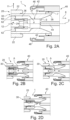
- Fig. 2A focuses on an auxiliary contact 60 that is electrically coupled to the first contact structure 20 in an otherwise substantially standard circuit-breaker 1.
- the auxiliary contact 60 extends into a auxiliary channel 36 and is configured for receiving an arc from an arcing zone 3 via the auxiliary channel 36.
- the auxiliary channel 36 leads from the arcing zone 3 to the auxiliary contact 60 and is configured for arc quenching by ablation of the nozzle structure 30.
- the auxiliary contact 60 extends into the auxiliary channel 36 in a location distant to the arcing zone 3.
- the auxiliary contact 60 extends in a radially outwards direction 11 from the first arcing contact 24.
- the auxiliary contact 60 extends across the auxiliary channel 36 in the radially outwards direction 11 across the entire width of the width of the auxiliary channel 36 in order to receive an arc.
- the auxiliary contact 60 extends across the auxiliary channel 36 in a circumferential direction 12 around the switching axis 2.
- the auxiliary contact 60 is in the shape of a circumferential protrusion and/or ring.
- the auxiliary contact 60 is a shoulder on a side of the first arcing contact 24 around the switching axis 2.
- the auxiliary contact 60 has a plurality of recesses 62 extending along the switching axis 2 for letting gas or fluid being guided through the auxiliary channel 36 pass.
- the recesses 62 are in the form of circumferentially distributed bores or cut-outs from the auxiliary contact 60.
- the auxiliary contact 60 is made of the same material as the first arcing contact 24.
- the auxiliary contact 60 is made of a different material compared to the first arcing contact 24.
- one is made of a first alloy and the other one is made of a second alloy, e.g. containing copper and/or tungsten or other metals.
- Figs. 2B, 2C and 2D are based on Fig. 2A and furthermore include different types of an arc A formed between the arcing contacts, namely the first arcing contact 24 and the second arcing contact 44.
- Fig. 2B shows how an arc referenced with "A" may be received by the first arcing contact 24 and the auxiliary contact 60.
- the auxiliary contact 60 may receive the arc A in different locations, e.g. even circumferentially or at least sectionally in a circumferential direction 12. Relative to the other Figs. 2C and 2D , it is that Fig. 2B represents the highest current being interrupted and thereby the largest arc A.
- Fig. 2C shows that an arc A may be received by the first arcing contact 24 only, e.g. due to low current and/or voltage being interrupted relative to Fig. 2B and 2D .
- Fig. 2D shown the situation that an arc A may be received by the auxiliary contact 60 only, e.g. due to enhanced conductivity in the auxiliary channel 36, e.g. from particles entrapped in the gas or fluid stream going into the auxiliary channel 36.
- the arc A When switching low currents (e.g. shunt reactor switching), the arc A may not be stabilized substantially in the arcing zone 3. With the design according to the shown embodiment it is intended to move the arc (e.g. re-ignition resulting in long arcing times) to the auxiliary contact 60 as shown in Fig. 2D .
- auxiliary contact 60 can be understood as a floating electrode, especially a conductive element embedded in the nozzle structure, particularly in the main nozzle 31 and/or auxiliary nozzle 33.
- the auxiliary contact 60 is meant to prevent discharges or arcs coming to deep into the auxiliary channel 36.
- discharges or arcs A coming into the auxiliary channel 36 may occur during reignition at arcing times shorter a minimum arcing time.
- the present invention now allows that discharges or arcs A may enter into the auxiliary channel 36 as the proposed design including the auxiliary contact 60 is adjusted not to suffer from the reignition into the auxiliary channel 36. Further on, the design provides that an initial discharge or arc A getting into the auxiliary channel 36 may commutate to an arc A at the tip of the tulip as shown in Fig. 2C or mainly at the tip of the tulip as shown in Figure 2B .
Landscapes
- Circuit Breakers (AREA)
Abstract
The invention relates to a circuit-breaker (1) for high-voltage applications comprising
a first contact structure (20) including a first arcing contact (24), and a nozzle structure (30) surrounding the first arcing contact (24) and having an auxiliary channel (38) leading to an arcing zone (3) adjacent to the first arcing contact (24);
a second contact structure (40) configured to make or break an electrical connection between the first contact structure (20) and the second contact structure (40) by moving the first and second contact structures (20, 40) at least partially relative to one another along a switching axis (2), the second contact structure (40) including a second arcing contact (44) corresponding to the first arcing contact (24); and
an auxiliary contact (60) electrically coupled to the first contact structure (20), the auxiliary contact (60) extending into the auxiliary channel (38) and configured for receiving an arc from the arcing zone (3) via the auxiliary channel (38).
a first contact structure (20) including a first arcing contact (24), and a nozzle structure (30) surrounding the first arcing contact (24) and having an auxiliary channel (38) leading to an arcing zone (3) adjacent to the first arcing contact (24);
a second contact structure (40) configured to make or break an electrical connection between the first contact structure (20) and the second contact structure (40) by moving the first and second contact structures (20, 40) at least partially relative to one another along a switching axis (2), the second contact structure (40) including a second arcing contact (44) corresponding to the first arcing contact (24); and
an auxiliary contact (60) electrically coupled to the first contact structure (20), the auxiliary contact (60) extending into the auxiliary channel (38) and configured for receiving an arc from the arcing zone (3) via the auxiliary channel (38).
Description
- The invention relates to a circuit-breaker, especially for high-voltage applications. The circuit-breaker comprises a first and a second contact structure and a nozzle structure. The circuit-breaker is configured to make or break an electrical connection between the first and second contact structures.
- Typically, arcing upon operating a circuit-breaker, e.g. making or breaking current and/or an electrical connection, especially at high voltages, results in wear of contact structures and of a nozzle structure of a circuit-breaker. Further, it has been found that electrical fields within a circuit-breaker may affect the arcing location or duration.
- It is a problem to provide continuous enhancement in circuit-breakers with regard to lifetime, wear and arc extinguishment.
- It is therefore an object of the invention to provide solutions with respect to circuit-breakers that provide an enhanced maintenance, reduced cost and increased lifetime. Particularly it is an object to avoid or reduce disadvantages of known solutions.
- The object of the invention is solved by the features of the independent claims. Preferred implementations are detailed in the dependent claims, the description and the figures.
- The object is particularly solved by a circuit-breaker for high-voltage applications comprising
- a first contact structure including a first arcing contact, and a nozzle structure surrounding the first arcing contact and having an auxiliary channel leading to an arcing zone adjacent to the first arcing contact;
- a second contact structure configured to make or break an electrical connection between the first contact structure and the second contact structure by moving the first and second contact structures at least partially relative to one another along a switching axis, the second contact structure including a second arcing contact corresponding to the first arcing contact; and
- an auxiliary contact electrically coupled to the first contact structure, the auxiliary contact extending into the auxiliary channel and configured for receiving an arc from the arcing zone via the auxiliary channel.
- In other words, particularly, the present invention suggests a high-voltage circuit-breaker which has contact elements that can form or withstand an arc upon operating the breaker (e.g. making or breaking the current), wherein the arc is to be located in an arcing area in front of the first contact element. A nozzle arranged substantially around the first contact element and with a duct is provided, which duct is in connection with the arcing area. One or both of the contact elements can be moved along an axis for switching of the breaker. A further contact element is provided that is coupled with the first contact element and that runs, e.g. radially away from the first contact element, within the duct so that an arc coming from the arcing area can be directed towards the further contact element. This helps in arc quenching and size reduction.
- The invention is facing and giving a solution for the problem that a space for the arc is typically limited by the size of the arcing contacts and the nozzle structure. High currents may need more surface of the nozzle and more surface of the arcing contacts, i.e. may be in contact with those on a greater surface area and/or may produce more wear on those. Constructing the circuit-breaker with respect to high currents therefore requires bigger arcing contacts and a bigger nozzle structure, which increases size and/or costs of the circuit-breaker. In this respect, the auxiliary contact is proposed.
- The auxiliary contact beneficially enables to even use the auxiliary channel for supporting arc quenching especially by ablation of the material forming the auxiliary channel.
- The proposed solution is based on the idea that an arc or discharge coming from the arcing zone can get into the auxiliary channel in the nozzle structure and shall be received by a certain contact that has the potential of the first arcing contact. Thus, the auxiliary channel may support arc extinguishment.
- The invention helps to not necessarily increase a size of the circuit-breaker although making it compatible for higher currents. In another sense, a size of the circuit-breaker may be reduced by way of the auxiliary contact while still being capable of the same height of currents.
- By means of the invention and by means of aspects described in the present application, it is advantageously realized that arc extinguishment is improved by way of utilizing the auxiliary channel in this respect. Thus, the nozzle structure and therewith the circuit-breaker has a longer lifetime. There may be less material damage occurring in the nozzle structure since the arcs may be directed to the auxiliary contact, if coming from the arcing zone through the auxiliary channel.
- Further advantageous implementations of the invention are given as follows. The features named in the implementations may be individually combined with each other or considered alone.
- It is noted that same names for features are meant to stand for same features as mentioned in the claims and throughout the description. This is particularly mentioned with respect to some features being referred to with indefinite articles despite having possibly being introduced in a preceding section. Accordingly, with matching feature names in cases with for example two or more indefinite articles of the feature names, the skilled person may adopt the corresponding description in each case.
- The circuit-breaker can make or break an electrical connection. The circuit-breaker may have or may be configured as an interrupter. The circuit-breaker may have a gas damper. The circuit-breaker may have a drive device. The gas damper and/or the drive device may be coupled with the first contact structure and/or the second contact structure. The circuit-breaker may have a housing for the contact structures and the nozzle structure. The housing may comprise a volume, especially filled with gas or fluid e.g. an insulating gas and/or dielectric gas or fluid. The housing is preferably provided gas-tight and/or comprises a tube-like or cylinder-like form extending along the switching axis. The drive device is preferably motorized and/or provided outside of the housing. In such implementation the drive device can be connected to the first contact structure or the second contact structure, especially via a pull rod. The drive device may comprise an additional damper, which can be associated and/or integrated to the drive device.
- The first and/or second contact structure typically relates to an assembly and/or means for an electrical connection. The first and/or second contact structure is typically at least partially and/or sectionally electrically conductive. For example, the first and/or second contact structure may have at least one contact. Typically, the first and/or second contact structure has an arcing contact and particularly a nominal contact. The arcing contact is meant for withstanding arcs during opening or closing of the circuit-breaker. The nominal contact is meant for nominal current conduction when the circuit-breaker is closed. The first and/or second contact structure may be formed at least substantially cylindrical and/or round.
- It is preferred that the first contact structure has a first nominal contact especially arranged radially outside the nozzle structure and/or the first arcing contact. The nozzle structure may be arranged between the first nominal contact and the first arcing contact. Particularly, the second contact structure includes a second nominal contact corresponding to the first nominal contact. By way of nominal contacts, high electrical currents can be conducted. One or both of the nominal contacts, especially the second nominal contact, may have and/or be covered by a shield, particularly dielectric shield to shield the contact electrically. The dielectric shield is not necessarily insulating. The dielectric shield may be dielectric and/or made of metal for guiding or controlling the electrical field, especially for shielding the nominal contact(s) from electrical fields.
- The first contact structure may have a first arcing contact and particularly a nozzle structure. The nozzle structure is particularly configured to surround and/or enclose the first arcing contact, particularly around the switching axis. The first arcing contact is typically at least sectionally or partially made of metal. The first arcing contact may comprise or consist of tungsten, copper gold and/or silver. The first arcing contact may have a tulip shape, particularly extending at least partially or sectionally along the switching axis.
- The nozzle structure may have a channel or auxiliary channel. The auxiliary channel particularly leads to an arcing zone preferably adjacent to the first arcing contact. The arcing zone is typically arranged in front of the first arcing contact and/or between the arcing contacts, for example along the switching axis. The auxiliary channel particularly connects the arcing zone with a heating volume for receiving heated gas or fluid coming from the arcing zone.
- The auxiliary channel may be referred to as a heating channel since it connects the heating volume with the arc zone and/or since it may guide heated gas or fluid away from the arcing zone. The arc zone may be referred to as a main channel for the arc to occur, to which main channel the auxiliary channel or heating channel is typically connected.
- The nozzle structure is typically, at least sectionally or partially, and preferably at least in the section forming the auxiliary channel and/or in a section forming the arcing zone, made of a polymer compound, especially a thermoplastic polymer compound, e.g. Polytetrafluoroethylene, PTFE for short. The nozzle structure may be formed at least substantially annular, particularly around the switching axis. The nozzle structure is typically configured for arc quenching and/or for guiding a fluid or a gas from or to the arcing zone. Also, the nozzle structure is typically configured for surrounding an arc established between the contact structures.
- The nozzle structure may have a main nozzle and/or an auxiliary nozzle. The main nozzle and/or the auxiliary nozzle may surround the first arcing contact and/or may have an/the annular shape. The auxiliary nozzle may be inserted into the main nozzle, particularly along the switching axis and/or a first direction. The nozzle structure, particularly the main nozzle, may form a part of the auxiliary channel particularly leading to the arcing zone.
- The nozzle structure may include a main nozzle throat and particularly an auxiliary nozzle throat. The main nozzle throat and particularly the auxiliary nozzle throat may constrict an/the arcing zone. The main nozzle throat and particularly the auxiliary nozzle throat may comprise an annular and/or cylindrical inner surface. The main nozzle throat and/or the auxiliary nozzle throat may have a diameter of at least 10 mm or at least 20 mm and/or of up to 40 mm or up to 50 mm; for example, the diameter may be 30 ± 10 mm for sufficient arc extinguishing properties. The main nozzle throat and the auxiliary nozzle throat may be in diameter at least substantially of the same size, i.e. by 10% or 5% or less difference in diameter; in other words, for example, the diameters of said throats may have the same size or may be different from each other by 10% or less, e.g. one being 20 mm and the other being 18 mm as a 10% difference . More particularly, the main nozzle throat may be at least 0,5 mm, 1 mm, 2 mm or more, and may be up to 1 mm, 2 mm, 3 mm or more larger than the auxiliary nozzle throat.
- Along the switching axis, the auxiliary channel may be arranged at least sectionally between the main nozzle throat and the auxiliary nozzle throat. Particularly, the auxiliary channel may point/run in a radially outwards direction from the arcing zone.
- Sectionally, the auxiliary channel may point/run along or in parallel to the switching axis.
- Typically, the arcing zone is arranged directly adjacent to the first arcing contact preferably along the switching axis. The arcing zone is typically configured for surrounding the second arcing contact. For example, the arcing zone surrounds the second arcing contact upon closing or opening the circuit-breaker, especially with the second arcing contact located inside the nozzle structure, especially the auxiliary nozzle and/or main nozzle.
- The main nozzle throat may be in front of the second contact structure. The auxiliary nozzle throat may be between the main nozzle throat and the first arcing contact. The main and auxiliary nozzle throats may be arranged substantially coaxially and particularly with respect to the switching axis. The nozzle throat(s) is/are configured for constricting the arc and/or for guiding of fluid or gas.
- The nozzle structure may have a main nozzle. The main nozzle particularly forms the main nozzle throat. The main nozzle particularly surrounds a main arcing section of the arcing zone. The main nozzle particularly provides an electrical insulation between the first contact structure and the second contact structure. The main nozzle particularly provides an electrical insulation between the first and second arcing contacts and between the first and second nominal contacts, respectively. The main arcing section may be arranged distant from to the first arcing contact.
- The nozzle structure may have an auxiliary nozzle. The auxiliary nozzle particularly forms the auxiliary nozzle throat. The auxiliary nozzle may surround an auxiliary arcing section of the arcing zone. The auxiliary nozzle may provide control of the arc, particularly guidance of the arc and/or pressure increase through vaporization. The auxiliary arcing section may be arranged adjacent or proximal to the first arcing contact and/or the main arcing section. The auxiliary nozzle may form a further part of the auxiliary channel particularly leading to the arcing zone.
- The nozzle structure may support the first nominal contact and particularly the second nominal contact, especially on an outside of the nozzle structure. The second nominal contact may run on the outside, particularly on a nozzle ring. The outside or outside surface of the nozzle structure may be at least substantially cylindrical.
- The second contact structure particularly includes a second arcing contact. The second arcing contact is particularly provided corresponding to the first arcing contact, e.g. to form the arc upon making or breaking the electrical connection. The second arcing contact is typically at least sectionally or partially made of metal. The second arcing contact may comprise or consist of tungsten, copper gold and/or silver. The second arcing contact may have a pin shape and/or plug shape, especially corresponding to the tulip shape and/or the first arcing contact. The second arcing contact may at least substantially or partially extend along the switching axis.
- The circuit-breaker, for example one or both of the second contact structures, is/are particularly configured to make and/or break electrical connections between the first contact structure and the second contact structure. In this respect, it is typically provided that the first and second contact structures can be moved at least partially relative to one another along the switching axis. For example, nominal contacts and/or arcing contacts may be movable, especially along the switching axis, relative to one another. It may be that one or both of a pair of corresponding contacts may be movable along the switching axis.
- It is preferred that the auxiliary channel leads to a heating volume. The nozzle structure, particularly the channel, is particularly configured for arc quenching especially by ablation of the nozzle structure. Generally, the nozzle structure may be configured for arc quenching especially by ablation of the nozzle structure. For example, with respect to arc quenching by ablation, the nozzle structure, particularly the auxiliary channel, especially the arcing zone, may be made of or formed with a polymer compound, especially PTFE, which is helpful in ablation. Ablation protects the material by way of a gas barrier being present between the arc and the adjacent especially insulating material.
- The term high voltage relates to voltages that exceed 1 kV. A high voltage preferably concerns nominal voltages in the range from above 72 kV to 800 kV, like 145 kV, 245 kV or 420 kV. Alternatively or additionally, the term high voltage means preferably a voltage above 12 kV or 36 kV or 72 kV or 1100 kV. A high voltage preferably relates to nominal voltages in the range from above 12 kV, 36 kV or 72 kV to 550 kV or 1100 kV, like 145 kV, 245 kV or 420 kV, or even more.
- A 'high-voltage application' typically relates to an industrial system or apparatus that involves voltage, e.g. in the energy industry or in energy-consuming facilities. Here, the circuit-breaker may be applied for making or braking electrical connections.
- The circuit-breaker may include one or more components such as, a puffer-type cylinder, a self-blast chamber, a pressure collecting space, a compression space, or puffer volume, and an expansion space. The circuit-breaker may effectuate interruption of the conductive connections by means of one or more of such components, thereby discontinuing flow of electrical current in the conductive connections, and/or extinction of the arc produced when the electrical connection is interrupted. The term "axial" typically designates an extension, distance etc. in the direction of the axis. The term "radial" typically designates an extension, distance etc. in a direction oblique or perpendicular to the axis. The term "cross-section" typically relates a plane perpendicular or in parallel to to a corresponding axis, e.g. the switching axis.
- High or medium voltage devices, such as circuit-breakers and switchgears are essential for the protection of technical equipment, especially in the high voltage range. For example, circuit-breakers are predominantly used for interrupting a current, when an electrical fault occurs. As an example, circuit-breakers have the task of opening arcing contacts, quench an arc, and keeping the arcing contacts apart from one another in order to avoid a current flow even in case of high electrical potential originating from the electrical fault itself. Circuit-breakers may break medium to high short circuit currents of typically 1 kA to 80 kA at medium to high voltages of 12 kV to 72 kV and up to 1200 kV. Thus, high or medium voltage devices accommodate high-voltage conductors such as conductors to which a high voltage is applied.
- The circuit-breaker may comprise and/or may be filled with a gas or fluid, especially insulating gas and/or dielectric insulation medium, especially configured for arc extinguishment. The insulating gas and/or dielectric insulation medium can be any suitable gas that enables to adequately extinguish the electric arc formed between the contact elements during a current interruption operation, such as, but not limited, to an inert gas as, for example, sulphur hexafluoride SF6. Specifically, the insulating gas used can be SF6 gas or any other dielectric insulation medium and/or insulating gas, may it be gaseous and/or liquid, and in particular can be a dielectric insulation gas or arc quenching gas. Such dielectric insulation medium and/or insulating gas can for example encompass media comprising an organofluorine compound, such organofluorine compound being selected from the group consisting of: a fluoroether, an oxirane, a fluoroamine, a fluoroketone, a fluoroolefin, a fluoronitrile, and mixtures and/or decomposition products thereof. Herein, the terms "fluoroether", "oxirane", "fluoroamine", "fluoroketone", "fluoroolefin" and "fluoronitrile" refer to at least partially fluorinated compounds. In particular, the term "fluoroether" encompasses both hydrofluoroethers and perfluoroethers, the term "oxirane" encompasses both hydrofluorooxiranes and perfluorooxiranes, the term "fluoroamine" encompasses both hydrofluoroamines and perfluoroamines, the term "fluoroketone" encompasses both hydrofluoroketones and perfluoroketones, the term "fluoroolefin" encompasses both hydrofluoroolefins and perfluoroolefins, and the term "fluoronitrile" encompasses both hydrofluoronitriles and perfluoronitriles. It can thereby be preferred that the fluoroether, the oxirane, the fluoroamine and the fluoroketone are fully fluorinated, i.e. perfluorinated.
- The insulating gas and/or dielectric insulation medium can be selected from the group consisting of: a hydrofluoroether, a perfluoroketone, a hydrofluoroolefin, a perfluoronitrile, and mixtures thereof. In particular, the term "fluoroketone" as used in the context of the present invention shall be interpreted broadly and shall encompass both fluoromonoketones and fluorodiketones or generally fluoropolyketones. Explicitly, more than a single carbonyl group flanked by carbon atoms may be present in the molecule. The term shall also encompass both saturated compounds and unsaturated compounds including double and/or triple bonds between carbon atoms. The at least partially fluorinated alkyl chain of the fluoroketones can be linear or branched and can optionally form a ring. The dielectric insulation medium and/or insulating gas may comprise at least one compound being a fluoromonoketone and/or comprising also heteroatoms incorporated into the carbon backbone of the molecules, such as at least one of: a nitrogen atom, oxygen atom and sulphur atom, replacing one or more carbon atoms. More preferably, the fluoromonoketone, in particular perfluoroketone, can have from 3 to 15 or from 4 to 12 carbon atoms and particularly from 5 to 9 carbon atoms. Most preferably, it may comprise exactly 5 carbon atoms and/or exactly 6 carbon atoms and/or exactly 7 carbon atoms and/or exactly 8 carbon atoms.
- Further, the insulating gas and/or dielectric insulation medium may comprise at least one compound being a fluoroolefin selected from the group consisting of: hydrofluoroolefins (HFO) comprising at least three carbon atoms, hydrofluoroolefins (HFO) comprising exactly three carbon atoms, trans-1,3,3,3-tetrafluoro-1-propene (HFO-1234ze), 2,3,3,3-tetrafluoro-1-propene (HFO-1234yf), and mixtures thereof. The organofluorine compound can also be a fluoronitrile, in particular a perfluoronitrile. In particular, the organofluorine compound can be a fluoronitrile, specifically a perfluoronitrile, containing two carbon atoms, and/or three carbon atoms, and/or four carbon atoms. More particularly, the fluoronitrile can be a perfluoroalkylnitrile, specifically perfluoroacetonitrile, perfluoropropionitrile (C2F5CN) and/or perfluoro-butyronitrile (C3F7CN). Most particularly, the fluoronitrile can be perfluoroisobutyronitrile (according to the formula (CF3)2CFCN) and/or perfluoro-2-methoxypropanenitrile (according to formula CF3CF(OCF3)CN). Of these, perfluoroisobutyronitrile (i.e. 2,3,3,3-tetrafluoro-2-trifluoromethyl propanenitrile alias i-C3F7CN) is particularly preferred due to its low toxicity. The dielectric insulation medium and/or insulating gas can further comprise a background gas or carrier gas different from the organofluorine compound (in particular different from the fluoroether, the oxirane, the fluoroamine, the fluoroketone and the fluoroolefin) and can in embodiments be selected from the group consisting of: air, N2, 02, CO2, a noble gas, H2; NO2, NO, N2O; fluorocarbons and in particular perfluorocarbons, such as CF4; CF3I, SF6; and mixtures thereof. For example, the dielectric insulating gas can be CO2 in an embodiment.
- The first nominal contact may extend to or project beyond at least one of the main nozzle throat, the main arcing section and/or the auxiliary nozzle throat (particularly considering that not necessarily all of these features are given in some embodiments) in a first direction. The first direction is particularly considered along the switching axis and towards the second nominal contact. Thus, the first nominal contact extends further towards the second nominal contact than usually known in prior art which supports a shift in the electrical field.
- With respect to a very advantageous embodiment of the invention, it is provided that that the first nominal contact extends to or projects beyond at least one of the first arcing contact, the auxiliary nozzle, the auxiliary nozzle throat, the auxiliary arcing section and/or the auxiliary channel, particularly considered in or along the first direction, and particularly projects beyond by a distance that equals or is more than an inner diameter of the first arcing contact or of the nozzle structure. In this respect, a distance which the first nominal contact may project beyond is beneficially chosen to exceed the inner diameter of the first arcing contact, the main nozzle throat and/or the auxiliary nozzle throat. This has been proved to further reduce the effect of wear or damage of the nozzle structure from arcs to dielectric properties of the circuit-breaker (e.g. voltage strength in open position).
- The first nominal contact may project beyond the main nozzle, the main nozzle throat and/or the main arcing section, particularly considered in the first direction, and particularly projects beyond by a distance that equals or is more than the inner diameter of the first arcing contact or of the nozzle structure. In this respect, a distance which the first nominal contact may project beyond is beneficially chosen to exceed the inner diameter of the first arcing contact, the main nozzle throat and/or the auxiliary nozzle throat. This has been proved to further reduce damage from arcing.
- The main nozzle may have a nozzle diffusor or also named nozzle diffuser. The nozzle diffusor may be arranged adjacent to the main nozzle or main nozzle throat. It may be provided that mainly or only the nozzle diffusor of the main nozzle is configured for an/the electrical insulation between the first contact structure and the second contact structure, for example by being relatively long along the switching axis. The nozzle diffusor is particularly formed monolithically with or on the main nozzle.
- The nozzle diffusor may be arranged opposite the first nominal contact and along the first direction adjacent to the main nozzle throat and/or the main arcing section. Preferably, the nozzle diffusor is along the first direction at least two, three, four or five times as long as the main nozzle throat. It may be that the nozzle diffusor is shaped conically and/or to surround the second arcing contact. The nozzle diffusor may have a concave and/or conus shape particularly at least substantially facing away from the first arcing contact.
- The circuit-breaker may comprise an auxiliary contact. The auxiliary contact particularly is electrically coupled to the first contact structure and/or may be formed with the first contact structure. It is beneficially provided that the auxiliary contact extends into the auxiliary channel especially radially and/or from a side of the auxiliary channel. The auxiliary contact may not extend into the auxiliary channel starting from the arcing zone and/or from the side of the first arcing contact facing the second arcing contact. Particularly, the auxiliary contact may be formed with and/or attached to the first arcing contact at a location remote from the arcing zone and particularly in order to penetrate into the auxiliary channel, e.g. distant to the arcing zone.
- The auxiliary contact may be monolithically formed with the first arcing contact. The auxiliary contact may be attached to the first arcing contact, e.g. bonded. The auxiliary contact may be made of the same material as the first arcing contact. The auxiliary contact is typically at least sectionally or partially made of metal. The auxiliary contact may comprise or consist of tungsten, copper gold and/or silver. The auxiliary contact may have a pin shape and/or may be in the form of a radially outside protrusion on the first arcing contact.
- 'Extending into the auxiliary channel' in the context of the auxiliary contact typically relates to being located at least partially inside the auxiliary channel. Typically, the auxiliary contact extends into the auxiliary channel at a location that is not meant for fluid to enter or leave the auxiliary channel, but particularly rather that is meant for fluid to be guided continuously between the arcing zone and a heating volume and/or an exhaust.
- The auxiliary contact is particularly configured for receiving an arc from the arcing zone via the auxiliary channel. Thereby, the auxiliary contact is particularly made to withstand arcing or arcs, at least for a number of times. The auxiliary contact is furthermore meant to be contacted by an arc that is guided into the auxiliary channel from its origin between the arcing contacts. Thereby, the arc can be handled in the auxiliary channel. Particularly, the arc may not go beyond the auxiliary contact in the case it enters the auxiliary channel.
- It is preferred that the auxiliary channel leads to the auxiliary contact. The nozzle structure, particularly the auxiliary channel in the section leading from the arcing zone to the auxiliary contact, is particularly configured for arc quenching especially by ablation of the nozzle structure. For example, with respect to arc quenching by ablation, the auxiliary channel adjacent to the auxiliary contact, may be made of or formed with a polymer compound, especially PTFE, which is helpful in ablation. Ablation protects the material by way of a gas barrier being present between the arc and the adjacent especially insulating material. Ablation may be usable in order to control the arc, particularly guide the arc and/or support a pressure increase through vaporization. Ablation may support an arc extinguishing gas flow.
- With respect to a very advantageous embodiment of the invention, it is provided that the auxiliary contact extends into the auxiliary channel in a location distant to the arcing zone. For example, the auxiliary contact may extend into the auxiliary channel at a location distant to the arcing zone and particularly even more distant to the second contact structure. The auxiliary contact may extend into the auxiliary channel in a radial outside/radially outwards direction and/or away from the first arcing contact. The auxiliary contact may extend across the auxiliary channel in the radially outwards direction.
- It is preferred that the auxiliary contact extends sectionally across the auxiliary channel in a circumferential direction around the switching axis.
- The auxiliary contact may have the shape of a protrusion and/or a ring and/or a shoulder on a side of the first arcing contact. The auxiliary contact may at least sectionally surround the first arcing contact around the switching axis. There may be a plurality of auxiliary contacts, e.g. wherein the auxiliary contacts are distributed along and/or around the first arcing contact and/or the auxiliary channel. The plurality of auxiliary contacts may contain two or more, e.g. three, four, five or a multiple thereof, auxiliary contacts. The plurality may be partially or fully formed monolithically with the first arcing contact for low electrical resistance.
- The auxiliary contact may have at least one or a plurality of recesses, especially extending along and/or in parallel to the switching axis and/or the first direction. For example, the recess(es) may be in the form of a bore or a hole though the auxiliary contact, e.g. for letting a fluid or gas pass while still receiving the arc.
- The term 'or' may be replaced by 'and/or' throughout the present disclosure. As such, where 'or' is used, it is not necessarily meant that merely alternatives are named.
- These and other aspects of the invention will be apparent from and elucidated with reference to the implementations described hereinafter.
- In the drawings:
-
Fig. 1 shows a schematic cross-section of a circuit-breaker, wherein a first nominal contact projects beyond a first arcing contact, an auxiliary nozzle throat, and an auxiliary channel, and extends to a main nozzle throat, and wherein an auxiliary contact extends into the auxiliary channel of the nozzle structure; and -
Fig. 2A-D shows a schematic cross-section of a circuit-breaker with a first contact structure including a nozzle structure and with a second contact structure configured for making or breaking an electrical connection, wherein an auxiliary contact extends into an auxiliary channel of the nozzle structure, wherein an open state (A) and three different arcing states, where different types of arcs are present, (B, C and D) are shown. - The description contains procedural or methodical aspects upon describing structural features of the invention; the structural features can be understood well in that way. It is emphasized to the reader that such structural features can be lifted from the described context without hesitation or the question of an intermediate generalization to form aspects of the invention. It is also emphasized to the reader that any the structural features described in the following can be understood as individual aspects of the invention to distinguish from known solutions, despite being possibly lifted from the context.
- In
Fig. 1 a circuit-breaker 1 is shown in a cross-section. The circuit-breaker 1 is configured to make or break an electrical connection. InFig. 1 , the circuit-breaker 1 is not making the electrical connection. The circuit-breaker 1 is in an open position. - The circuit-
breaker 1 is filled with insulating gas configured for arc extinguishment. The circuit-breaker 1 is configured for high-voltage applications, e.g. applications involving a voltage above 72 kV. - Generally, the circuit-
breaker 1 may be moved/actuated into a closed position in which the electrical connection is made. The circuit-breaker 1 may be moved/actuated into the open position in which the electrical connection is undone or not present. Thus, the circuit-breaker 1 can make or break an electrical connection. It may also be said that the circuit-breaker 1 can make and break an electrical connection. - The circuit-
breaker 1 has afirst contact structure 20 including a firstnominal contact 22, afirst arcing contact 24, and anozzle structure 30. Thenozzle structure 30 surrounds thefirst arcing contact 24. Thenozzle structure 30 includes amain nozzle throat 32 and anauxiliary nozzle throat 34. Further, thenozzle structure 30 includes anauxiliary channel 36 that leads to anarcing zone 3 adjacent to the first arcing contact. Further, especially opposite the arcing zone 3 (towards the left inFig. 1 ), theauxiliary channel 36 leads to a heating volume. Preferably, an exhaust is connected to an exhaust tube that is connected to thefirst arcing contact 24, particularly tulip shape, and on the other side to a diffusor. - Presently, the
first contact structure 20, especially the firstnominal contact 22, thefirst arcing contact 24, thenozzle structure 30, theauxiliary channel 36, are at least sectionally and/or partially substantially annular shaped which provides symmetry around a switchingaxis 2. - The circuit-
breaker 1 has asecond contact structure 40 including a secondnominal contact 42 and asecond arcing contact 44. Presently, thesecond contact structure 40, especially the secondnominal contact 42, is at least sectionally and/or partially substantially annular shaped which provides symmetry around the switchingaxis 2. The secondnominal contact 42 surrounds thesecond arcing contact 44. Thesecond arcing contact 24 is shaped substantially symmetrical and/or cylindrical around the switchingaxis 2. - The circuit-
breaker 1, especially thesecond contact structure 40, is configured to make or break the electrical connection between the first 20 and the second 40 contact structure by moving the first andsecond contact structures axis 2. Particularly, thesecond contact structure 40 is movably arranged relative to thefirst contact structure 20 with respect to each of its parts. The secondnominal contact 42 and thesecond arcing contact 44 can be moved along the switchingaxis 2, especially independently. - The second
nominal contact 44 can get into contact with the firstnominal contact 42 when the circuit-breaker 1 is being closed. The secondnominal contact 44 is configured to surround the firstnominal contact 24. - The
first arcing contact 24 has a tulip shape and thesecond arcing contact 44 has a pin shape or plug shape extending along the switchingaxis 2. Thesecond arcing contact 44 can be plugged into thefirst arcing contact 24. Thesecond arcing contact 42 can get into contact with thefirst arcing contact 22 when the circuit-breaker 1 is being closed. Thefirst arcing contact 22 is configured to surround thesecond arcing contact 42. - The arcing
contacts - The second
nominal contact 42 corresponds to the firstnominal contact 22. Thesecond arcing contact 44 corresponds to thefirst arcing contact 24. Particularly, thecontacts contacts axis 2 individually relative to one another especially to selectively and/or successively make or break the electrical connection including a management of arcing between the arcingcontacts - The first
nominal contact 22 is arranged radially outside thenozzle structure 30 and thefirst arcing contact 24. Thenozzle structure 30 is arranged between the firstnominal contact 22 and thefirst arcing contact 24. The secondnominal contact 42 is covered by a particularlydielectric shield 46. - The
nozzle structure 30 includes amain nozzle throat 32 and anauxiliary nozzle throat 34 constricting thearcing zone 3 adjacent, especially directly adjacent, to thefirst arcing contact 24 along the switchingaxis 2 and configured for surrounding thesecond arcing contact 44. Thenozzle throats - The
arcing zone 3 especially begins along thefirst direction 8 and/or the switchingaxis 2 directly at and/or in front of thefirst arcing contact 24. Thearcing zone 3 especially ends along thefirst direction 8 and/or the switchingaxis 2 at the end of the nozzle throat, particularly themain nozzle throat 32. Thearcing zone 3 is typically at least substantially cylindrically shaped. - A
main nozzle 31 of thenozzle structure 30 forms themain nozzle throat 32 and surrounds amain arcing section 4 of thearcing zone 3. Themain nozzle 31 provides a distance between thefirst arcing contact 24 and the firstnominal contact 22. Themain nozzle 32 forms a part of theauxiliary channel 36. Themain nozzle 32 may be a monolithically shaped part, especially made from a polymer compound, i.e. plastic. - An
auxiliary nozzle 33 of thenozzle structure 30 forms theauxiliary nozzle throat 34 and surrounds anauxiliary arcing section 5 of thearcing zone 3. The auxiliary nozzle provides a distance between thefirst arcing contact 24 and the firstnominal contact 22. Theauxiliary nozzle 33 forms a further part of theauxiliary channel 36. Theauxiliary nozzle 33 may be a monolithically shaped part, especially made from a polymer compound, i.e. plastic. Themain nozzle 32 and theauxiliary nozzle 33 surround thefirst arcing contact 24. Thenozzles nozzles - The
nozzle structure 30, especially themain nozzle 31, supports the firstnominal contact 22 and the secondnominal contact 42 on an outside or outside surface of thenozzle structure 30, particularly which outside surface ist at least substantially cylindrically shaped. Themain nozzle 31 and theauxiliary nozzle 33 surround thefirst arcing contact 24 and optionally thesecond arcing contact 44. The second nominal 42 contact runs on the outside, particularly on anozzle ring 7. - The
nozzle structure 30, especially themain nozzle 31 and theauxiliary nozzle 33, consist of the polymer compound Polytetrafluoroethylene, PTFE for short. In this way, thenozzle structure 30 is configured for arc quenching by ablation of the plastic material, i.e. PTFE, of thenozzle structure 30. - The
nozzle structure 30, namely themain nozzle 31, has and/or forms anozzle diffusor 38 that is configured for an electrical insulation between the first 20 and the second 40 contact structure. Thenozzle diffusor 38 is arranged and extends opposite the firstnominal contact 22 along the switchingaxis 2. Thenozzle diffusor 38 is arranged adjacent to themain nozzle throat 32, and adjacent to themain arcing section 4. Thenozzle diffusor 38 is shaped conically to surround thesecond arcing contact 44. Thenozzle diffusor 38 is integrated with themain nozzle 31. - According to a first aspect of the embodiment of
Fig. 1 , it is provided that the firstnominal contact 22 extends to and even projects beyond themain nozzle throat 32 and theauxiliary nozzle throat 34 in afirst direction 8 along, particularly in parallel to, the switchingaxis 2 and towards the secondnominal contact 42. - Further, the first
nominal contact 22 projects beyond theauxiliary nozzle throat 34 and theauxiliary channel 36 in thefirst direction 8 by a distance 6. Particularly, said distance 6 is more than an inner diameter 9 of thefirst arcing contact 24 and aninner diameter 10 of thenozzle structure 30, particularly of themain nozzle 33 and/or of theauxiliary nozzle 33. - Further, the first
nominal contact 22 projects beyond themain nozzle throat 32 in thefirst direction 8 by the distance 6. Particularly, said distance 6 is more than the inner diameter 9 of thefirst arcing contact 24 and the inner diameter of thenozzle structure 30, particularly of themain nozzle 33 and/or of theauxiliary nozzle 33. - Presently, only the
nozzle diffusor 38 of themain nozzle 31 is configured for an electrical insulation between thefirst contact structure 20 and thesecond contact structure 40. Particularly, thenozzle diffusor 38 forms a front end of thefirst contact structure 20. - The
nozzle diffusor 38 is along thefirst direction 8 and/or the switchingaxis 2 at least two, or four times as long as themain nozzle throat 32. Thenozzle diffusor 38 is shaped conically and concave to surround thesecond arcing contact 44. The conical and concave shape is arranged to face away from thefirst arcing contact 24. - The
first contact structure 20, thenozzle structure 30 and/or thesecond contact structure 40 are at least sectionally, substantially, partially and/or fully shaped circumferentially around the switchingaxis 2. - According to a second aspect of the embodiment of
Fig. 1 anauxiliary contact 60 is provided. Theauxiliary contact 60 is electrically coupled to thefirst contact structure 20 by being monolithically formed with thefirst arcing contact 24. - The
auxiliary contact 60 extends into theauxiliary channel 36 and is configured for receiving an arc from thearcing zone 3 via theauxiliary channel 36. Theauxiliary channel 36 leads from thearcing zone 3 to theauxiliary contact 60 and is configured for arc quenching by ablation of thenozzle structure 30. - The
auxiliary contact 60 extends into theauxiliary channel 36 in a location distant to thearcing zone 3. Theauxiliary contact 60 extends in a radially outwardsdirection 11 from thefirst arcing contact 24. Theauxiliary contact 60 extends across theauxiliary channel 36 in the radially outwardsdirection 11 across at least 10 % of the width of theauxiliary channel 36 in order to receive an arc. - It may be that the
auxiliary contact 60 forms a surface of theauxiliary channel 36 and/or has a substantially stepless transition with theauxiliary channel 36. In this case, theauxiliary contact 60 may as well receive an arc. - The
auxiliary contact 60 extends across theauxiliary channel 36 in acircumferential direction 12 around the switchingaxis 2. Theauxiliary contact 60 is in the shape of a sectional protrusion and/or ring, particularly a shoulder on a side of thefirst arcing contact 24 around the switchingaxis 2. - The
auxiliary contact 60 hasrecesses 62 extending along the switchingaxis 2 for letting gas or fluid being guided through theauxiliary channel 36 pass. Therecesses 62 are in the form of circumferentially distributed bores or cut-outs from theauxiliary contact 60. - The
auxiliary contact 60 is made of the same material as thefirst arcing contact 24. - In other embodiments it can be realized that the
auxiliary contact 60 is made of a different material compared to thefirst arcing contact 24. For example, one is made of a first alloy and the other one is made of a second alloy, e.g. containing copper and/or tungsten or other metals. - In
Fig. 2 a further embodiment of a circuit-breaker 1 is shown in a cross-section along a switchingaxis 2. - This embodiment is substantially similar to that of
Fig. 1 with the note that the features with respect to the second aspect described above are substantially absent. In other words, particularly, the embodiment ofFig. 2 does not exhibit anauxiliary contact 60. - The embodiment of
Fig. 2 focuses on a firstnominal contact 22 extending beyond amain nozzle throat 32 and anauxiliary nozzle throat 34 in afirst direction 8 along the switchingaxis 2 and towards the second nominal contact. - It applies that same references and corresponding description can be applied in the comparison between
Figs. 1 and2 . - In
Fig. 2 a further embodiment of a circuit-breaker 1 is shown in a cross-section along a switchingaxis 2. - This embodiment is substantially similar to that of
Fig. 1 with the note that the features with respect to the first aspect described above are substantially absent and the second aspect described above are amended (to be discusses in the following). - In other words, particularly, the embodiment of
Fig. 2 does not exhibit that a firstnominal contact 22 extends to or projects beyond: afirst arcing contact 24, amain nozzle throat 32, and/or anauxiliary nozzle throat 34 in afirst direction 8 along the switchingaxis 2 and towards the secondnominal contact 42. - The embodiment of
Fig. 2A focuses on anauxiliary contact 60 that is electrically coupled to thefirst contact structure 20 in an otherwise substantially standard circuit-breaker 1. - The
auxiliary contact 60 extends into aauxiliary channel 36 and is configured for receiving an arc from anarcing zone 3 via theauxiliary channel 36. - It applies that same references and corresponding description can be applied in the comparison between
Figs. 1 and2 . - The
auxiliary channel 36 leads from thearcing zone 3 to theauxiliary contact 60 and is configured for arc quenching by ablation of thenozzle structure 30. - The
auxiliary contact 60 extends into theauxiliary channel 36 in a location distant to thearcing zone 3. Theauxiliary contact 60 extends in a radially outwardsdirection 11 from thefirst arcing contact 24. Theauxiliary contact 60 extends across theauxiliary channel 36 in the radially outwardsdirection 11 across the entire width of the width of theauxiliary channel 36 in order to receive an arc. - The
auxiliary contact 60 extends across theauxiliary channel 36 in acircumferential direction 12 around the switchingaxis 2. Theauxiliary contact 60 is in the shape of a circumferential protrusion and/or ring. Theauxiliary contact 60 is a shoulder on a side of thefirst arcing contact 24 around the switchingaxis 2. - The
auxiliary contact 60 has a plurality ofrecesses 62 extending along the switchingaxis 2 for letting gas or fluid being guided through theauxiliary channel 36 pass. Therecesses 62 are in the form of circumferentially distributed bores or cut-outs from theauxiliary contact 60. - The
auxiliary contact 60 is made of the same material as thefirst arcing contact 24. - In other embodiments it can be realized that the
auxiliary contact 60 is made of a different material compared to thefirst arcing contact 24. For example, one is made of a first alloy and the other one is made of a second alloy, e.g. containing copper and/or tungsten or other metals. -
Figs. 2B, 2C and 2D are based onFig. 2A and furthermore include different types of an arc A formed between the arcing contacts, namely thefirst arcing contact 24 and thesecond arcing contact 44. -
Fig. 2B shows how an arc referenced with "A" may be received by thefirst arcing contact 24 and theauxiliary contact 60. Theauxiliary contact 60 may receive the arc A in different locations, e.g. even circumferentially or at least sectionally in acircumferential direction 12. Relative to the otherFigs. 2C and 2D , it is thatFig. 2B represents the highest current being interrupted and thereby the largest arc A. -
Fig. 2C shows that an arc A may be received by thefirst arcing contact 24 only, e.g. due to low current and/or voltage being interrupted relative toFig. 2B and 2D . -
Fig. 2D shown the situation that an arc A may be received by theauxiliary contact 60 only, e.g. due to enhanced conductivity in theauxiliary channel 36, e.g. from particles entrapped in the gas or fluid stream going into theauxiliary channel 36. - When switching low currents (e.g. shunt reactor switching), the arc A may not be stabilized substantially in the
arcing zone 3. With the design according to the shown embodiment it is intended to move the arc (e.g. re-ignition resulting in long arcing times) to theauxiliary contact 60 as shown inFig. 2D . - Typically, discharges or arcs A in the
auxiliary channel 36 are to be prevented due to reliability issues. The presently described embodiments provide an electrode in theauxiliary channel 36 by means of theauxiliary contact 60. Theauxiliary contact 60 can be understood as a floating electrode, especially a conductive element embedded in the nozzle structure, particularly in themain nozzle 31 and/orauxiliary nozzle 33. Theauxiliary contact 60 is meant to prevent discharges or arcs coming to deep into theauxiliary channel 36. - It has been found that discharges or arcs A coming into the
auxiliary channel 36 may occur during reignition at arcing times shorter a minimum arcing time. The present invention now allows that discharges or arcs A may enter into theauxiliary channel 36 as the proposed design including theauxiliary contact 60 is adjusted not to suffer from the reignition into theauxiliary channel 36. Further on, the design provides that an initial discharge or arc A getting into theauxiliary channel 36 may commutate to an arc A at the tip of the tulip as shown inFig. 2C or mainly at the tip of the tulip as shown inFigure 2B . -
- 1
- circuit-breaker
- 2
- switching axis
- 3
- arcing zone
- 4
- main arcing section
- 5
- auxiliary arcing section
- 6
- distance
- 7
- nozzle ring
- 8
- direction
- 9
- diameter
- 10
- diameter
- 11
- radially outwards direction
- 12
- circumferential direction
- 20
- first contact structure
- 22
- first nominal contact
- 24
- first arcing contact
- 30
- nozzle structure
- 31
- main nozzle
- 32
- main nozzle throat
- 33
- auxiliary nozzle
- 34
- auxiliary nozzle throat
- 36
- auxiliary channel
- 38
- nozzle diffusor
- 40
- second contact structure
- 42
- second nominal contact
- 44
- second arcing contact
- 46
- shield
- 60
- auxiliary contact
- 62
- recess
Claims (15)
- Circuit-breaker (1) for high-voltage applications comprisinga first contact structure (20) including a first arcing contact (24), and a nozzle structure (30) surrounding the first arcing contact (24) and having an auxiliary channel (38) leading to an arcing zone (3) adjacent to the first arcing contact (24);a second contact structure (40) configured to make or break an electrical connection between the first contact structure (20) and the second contact structure (40) by moving the first and second contact structures (20, 40) at least partially relative to one another along a switching axis (2), the second contact structure (40) including a second arcing contact (44) corresponding to the first arcing contact (24); andan auxiliary contact (60) electrically coupled to the first contact structure (20), the auxiliary contact (60) extending into the auxiliary channel (38) and configured for receiving an arc from the arcing zone (3) via the auxiliary channel (38).
- Circuit-breaker (1) according to any one of the preceding claims, wherein the auxiliary channel (38) leads to the auxiliary contact (60) and is configured for arc quenching by ablation of the nozzle structure (30), and particularly wherein the nozzle structure (30) is configured for arc quenching by ablation of the nozzle structure (30).
- Circuit-breaker (1) according to any one of the preceding claims, wherein the auxiliary contact (60) extends into the auxiliary channel (38) in a location distant to the arcing zone (3).
- Circuit-breaker (1) according to the preceding claim, wherein the auxiliary contact (60) extends in a radially outwards direction (11) from the first arcing contact (24), and/or wherein the auxiliary contact (60) extends across the auxiliary channel (38) in the radially outwards direction (11).
- Circuit-breaker (1) according to any one of the preceding claims, wherein the auxiliary contact (60) extends sectionally across the auxiliary channel (38) in a circumferential direction (12) around the switching axis (2), and/or wherein the auxiliary contact (60) has recesses (62) extending along the switching axis (2).
- Circuit-breaker (1) according to any one of the preceding claims, wherein the first contact structure (20) has a first nominal contact (22) arranged radially outside the nozzle structure (30) and/or the first arcing contact (24), particularly wherein the nozzle structure (30) is arranged between the first nominal contact (22) and the first arcing contact (24), and particularly wherein the second contact structure (40) includes a second nominal contact (42) corresponding to the first nominal contact (22).
- Circuit-breaker (1) according to the preceding claim, wherein the nozzle structure (30) includes a main nozzle throat (32) and particularly an auxiliary nozzle throat (34), the main nozzle throat (32) and particularly the auxiliary nozzle throat (34) constricting the arcing zone (3) adjacent to the first arcing contact (24) and configured for surrounding the second arcing contact (44).
- Circuit-breaker (1) according to any one of the preceding claims, wherein the nozzle structure (30) has a main nozzle (31) forming the main nozzle throat (32) and surrounding a main arcing section (4) of the arcing zone (3) and providing an electrical insulation between the first arcing contact (24) and the first nominal contact (22).
- Circuit-breaker (1) according to any one of the preceding claims, wherein the nozzle structure (30) has an auxiliary nozzle (33) forming the auxiliary nozzle throat (34) and surrounding a auxiliary arcing section (5) of the arcing zone (3) and providing an electrical insulation between the first arcing contact (24) and the first nominal contact (22).
- Circuit-breaker (1) according to any one of the preceding claims, wherein the nozzle structure (30) supports the first nominal contact (22) and the second nominal contact (42), especially on an outside of the nozzle structure (30).
- Circuit-breaker (1) according to any one of the preceding claims, wherein the main nozzle (31) and/or the auxiliary nozzle (33) surround(s) the first arcing contact (24).
- Circuit-breaker (1) according to any one of the preceding claims, wherein the nozzle structure (30) comprises or consists of a polymer compound, especially PTFE, and/or wherein the second nominal contact (42) is covered by an insulating shield (46).
- Circuit-breaker (1) according to any one of the preceding claims, wherein the first arcing contact (24) has a tulip shape and/or wherein the second arcing contact (44) has a pin shape extending at least partially along the switching axis (2).
- Circuit-breaker (1) according to the preceding claim, wherein the first nominal contact (22) extends to or projects beyond the first arcing contact (24), especially the main nozzle throat (32) and/or the auxiliary nozzle throat (34), in a first direction (8) along the switching axis (2) and towards the second nominal contact (42), particularly whereinthe first nominal contact (22) extends to or projects beyond the auxiliary nozzle throat (34), the auxiliary arcing section (5) and/or the auxiliary channel (36) in the first direction (8), especially projects beyond by a distance (6) that equals or is more than an inner diameter (9, 10) of the first arcing contact (24) or of the nozzle structure (30); and/orthe first nominal contact (22) extends to or projects beyond the main nozzle throat (32) and/or the main arcing section (4) in the first direction (8), especially projects beyond by a distance (6) that equals or is more than an inner diameter (9, 10) of the first arcing contact (24) or of the nozzle structure (30).
- Circuit-breaker (1) according to of the preceding claim, wherein only a nozzle diffusor (38) of the main nozzle (31) is configured for an electrical insulation between the first contact structure (20) and the second contact structure (40), particularly wherein the nozzle diffusor (38)is arranged opposite the first nominal contact (22) and along the first direction (8) adjacent to the main nozzle throat (32) and/or the main arcing section (4), and wherein only the nozzle diffusor (38) of the nozzle structure (30) is configured for the electrical insulation between the first contact structure (20) and the second contact structure (40), and/oris along the first direction (8) at least two, three, four or five times as long as the main nozzle throat (32), and/or wherein the nozzle diffusor (38) is shaped conically to surround the second arcing contact (44).
Priority Applications (1)
| Application Number | Priority Date | Filing Date | Title |
|---|---|---|---|
| EP23206804.9A EP4550379A1 (en) | 2023-10-30 | 2023-10-30 | Circuit-breaker with a nozzle structure |
Applications Claiming Priority (1)
| Application Number | Priority Date | Filing Date | Title |
|---|---|---|---|
| EP23206804.9A EP4550379A1 (en) | 2023-10-30 | 2023-10-30 | Circuit-breaker with a nozzle structure |
Publications (1)
| Publication Number | Publication Date |
|---|---|
| EP4550379A1 true EP4550379A1 (en) | 2025-05-07 |
Family
ID=88600235
Family Applications (1)
| Application Number | Title | Priority Date | Filing Date |
|---|---|---|---|
| EP23206804.9A Pending EP4550379A1 (en) | 2023-10-30 | 2023-10-30 | Circuit-breaker with a nozzle structure |
Country Status (1)
| Country | Link |
|---|---|
| EP (1) | EP4550379A1 (en) |
Citations (4)
| Publication number | Priority date | Publication date | Assignee | Title |
|---|---|---|---|---|
| US6040970A (en) * | 1996-04-22 | 2000-03-21 | Siemens Ag | Interrupter unit of a high-voltage power circuit breaker |
| US7595461B2 (en) * | 2004-12-23 | 2009-09-29 | Abb Technology Ag | Heavy-duty circuit breaker with erosion-resistant short-circuit current routing |
| US20110297648A1 (en) * | 2009-02-13 | 2011-12-08 | Siemens Aktiengesellschaft | High-voltage power switch having a contact gap equipped with switching gas deflection elements |
| EP3926654A1 (en) * | 2020-06-17 | 2021-12-22 | ABB Power Grids Switzerland AG | Circuit breaker with field deflection element |
-
2023
- 2023-10-30 EP EP23206804.9A patent/EP4550379A1/en active Pending
Patent Citations (4)
| Publication number | Priority date | Publication date | Assignee | Title |
|---|---|---|---|---|
| US6040970A (en) * | 1996-04-22 | 2000-03-21 | Siemens Ag | Interrupter unit of a high-voltage power circuit breaker |
| US7595461B2 (en) * | 2004-12-23 | 2009-09-29 | Abb Technology Ag | Heavy-duty circuit breaker with erosion-resistant short-circuit current routing |
| US20110297648A1 (en) * | 2009-02-13 | 2011-12-08 | Siemens Aktiengesellschaft | High-voltage power switch having a contact gap equipped with switching gas deflection elements |
| EP3926654A1 (en) * | 2020-06-17 | 2021-12-22 | ABB Power Grids Switzerland AG | Circuit breaker with field deflection element |
Similar Documents
| Publication | Publication Date | Title |
|---|---|---|
| US11087939B2 (en) | Device for interrupting non-short circuit currents only, in particular disconnector or earthing switch | |
| EP4256596B1 (en) | Electrical switching device | |
| US20110163069A1 (en) | Gas-insulated high-voltage switch | |
| CN111466006B (en) | Gas-insulated high-voltage or medium-voltage circuit breakers | |
| CN111630622B (en) | Gas-insulated high-or medium-voltage circuit breaker | |
| EP4550380A1 (en) | Circuit-breaker with a nozzle structure | |
| EP4141901B1 (en) | Metal enclosed circuit breaker | |
| US20190172668A1 (en) | Gas-insulated high-voltage switching device with improved main nozzle | |
| EP4117006B1 (en) | Gas-insulated high or medium voltage circuit breaker | |
| EP3826042B1 (en) | Arcing contact tulip with flow optimized slits and integrated stress relief feature | |
| US20260120987A1 (en) | High voltage circuit-breaker | |
| EP4738416A1 (en) | Circuit-breaker | |
| EP4432326A1 (en) | High voltage circuit-breaker | |
| EP4125108A1 (en) | Gas-insulated high or medium voltage circuit breaker | |
| EP3132461A1 (en) | High voltage switching device with auxiliary nozzle |
Legal Events
| Date | Code | Title | Description |
|---|---|---|---|
| PUAI | Public reference made under article 153(3) epc to a published international application that has entered the european phase |
Free format text: ORIGINAL CODE: 0009012 |
|
| STAA | Information on the status of an ep patent application or granted ep patent |
Free format text: STATUS: THE APPLICATION HAS BEEN PUBLISHED |
|
| AK | Designated contracting states |
Kind code of ref document: A1 Designated state(s): AL AT BE BG CH CY CZ DE DK EE ES FI FR GB GR HR HU IE IS IT LI LT LU LV MC ME MK MT NL NO PL PT RO RS SE SI SK SM TR |
|
| STAA | Information on the status of an ep patent application or granted ep patent |
Free format text: STATUS: REQUEST FOR EXAMINATION WAS MADE |
|
| 17P | Request for examination filed |
Effective date: 20251104 |