EP4550292A1 - Visual alarm, visual alarm inspection method, electronic device, and storage medium - Google Patents
Visual alarm, visual alarm inspection method, electronic device, and storage medium Download PDFInfo
- Publication number
- EP4550292A1 EP4550292A1 EP23742410.6A EP23742410A EP4550292A1 EP 4550292 A1 EP4550292 A1 EP 4550292A1 EP 23742410 A EP23742410 A EP 23742410A EP 4550292 A1 EP4550292 A1 EP 4550292A1
- Authority
- EP
- European Patent Office
- Prior art keywords
- light
- lens
- visual alarm
- alarm device
- illuminance
- Prior art date
- Legal status (The legal status is an assumption and is not a legal conclusion. Google has not performed a legal analysis and makes no representation as to the accuracy of the status listed.)
- Pending
Links
Images



Classifications
-
- G—PHYSICS
- G08—SIGNALLING
- G08B—SIGNALLING SYSTEMS, e.g. PERSONAL CALLING SYSTEMS; ORDER TELEGRAPHS; ALARM SYSTEMS
- G08B29/00—Checking or monitoring of signalling or alarm systems; Prevention or correction of operating errors, e.g. preventing unauthorised operation
- G08B29/02—Monitoring continuously signalling or alarm systems
- G08B29/10—Monitoring of the annunciator circuits
-
- G—PHYSICS
- G08—SIGNALLING
- G08B—SIGNALLING SYSTEMS, e.g. PERSONAL CALLING SYSTEMS; ORDER TELEGRAPHS; ALARM SYSTEMS
- G08B5/00—Visible signalling systems, e.g. visible personal calling systems or remote indication of seats occupied
- G08B5/22—Visible signalling systems, e.g. visible personal calling systems or remote indication of seats occupied using electric transmission; using electromagnetic transmission
- G08B5/36—Visible signalling systems, e.g. visible personal calling systems or remote indication of seats occupied using electric transmission; using electromagnetic transmission using visible light sources
-
- G—PHYSICS
- G08—SIGNALLING
- G08B—SIGNALLING SYSTEMS, e.g. PERSONAL CALLING SYSTEMS; ORDER TELEGRAPHS; ALARM SYSTEMS
- G08B5/00—Visible signalling systems, e.g. visible personal calling systems or remote indication of seats occupied
- G08B5/22—Visible signalling systems, e.g. visible personal calling systems or remote indication of seats occupied using electric transmission; using electromagnetic transmission
- G08B5/36—Visible signalling systems, e.g. visible personal calling systems or remote indication of seats occupied using electric transmission; using electromagnetic transmission using visible light sources
- G08B5/38—Visible signalling systems, e.g. visible personal calling systems or remote indication of seats occupied using electric transmission; using electromagnetic transmission using visible light sources using flashing light
Definitions
- the present application relates to the technical field of fire protection, and in particular to a visual alarm device, a method for detecting a visual alarm device, an electronic device and a storage medium.
- Visual alarm devices are a kind of fire alarm equipment. When a fire occurs, a visual alarm device flashes to alert people to escape and evacuate. It is an important way for hearing-impaired people to obtain fire alarm information. Visual alarm devices are usually installed on the ceiling or walls, and may be blocked during use, resulting in failure of the flashing light to provide an effective warning. For example, dust, coatings or other objects on visual alarm devices will affect the alarm effect of the devices. Therefore, it is necessary to test visual alarm devices to determine whether they can send alarms normally.
- the visual alarm device, method for detecting a visual alarm device, electronic device and storage medium provided by the present application can improve user experience of visual alarm devices.
- a visual alarm device comprising: a light source, a lens, a processing module and a light sensing module; the light source and the light sensing module are both located on an inner side of the lens, and the processing module is connected to the light sensing module; the lens is constructed to transmit light emitted by the light source; the light sensing module is used to sense the light from the lens side when the light source is turned on, generate an illuminance signal used to indicate the light intensity of the sensed light, and send the illuminance signal to the processing module; the processing module is used to send a first fault signal to a management terminal when it is determined that the light intensity sensed by the sensing module is greater than a first illuminance threshold according to the illuminance signal, wherein the first fault signal is used to indicate that the visual alarm device is blocked.
- the light from the lens side comprises at least one of: light reflected from an inner surface of the lens, light emitted from an outer surface of the lens, and light transmitted from an outer side of the lens to the inner side of the lens.
- the processing module is also used to send a second fault signal to the management terminal when it is determined that the light intensity sensed by the sensing module is smaller than a second illuminance threshold according to the illuminance signal, wherein the second illuminance threshold is smaller than the first illuminance threshold, and the second fault signal is used to indicate that the light source is faulty.
- the light sensing module comprises: at least two light sensors; the at least two light sensors are arranged at different positions on the inner side of the lens, and the at least two light sensors are respectively connected to the processing module; the at least two light sensors are used to respectively sense light from the lens side when the light source is turned on, generate an illuminance signal used to indicate a light intensity of the sensed light, and send the generated illuminance signal to the processing module; the processing module is used to send the first fault signal to the management terminal when the light intensity indicated by the illuminance signal sent by at least one of the light sensors is greater than the first illuminance threshold, and send the second fault signal to the management terminal when the light intensities indicated by the illuminance signals sent by both of the light sensors are smaller than the second illuminance threshold.
- the outer side of the lens is a convex surface
- the inner side of the lens is provided with a cross-shaped concave portion
- the concave portion comprises a first groove and a second groove that are orthogonal
- the light source is arranged in a cavity where the first groove and the second groove intersect
- the inner side of the lens comprises four refraction regions located between the first groove and the second groove, and each of the refraction regions is provided with at least one of the light sensors.
- one of the light sensors is arranged on each of the refraction regions, and a light sensing surface of the light sensors faces the outer side of the lens; for each of the light sensors, the angle between the vertical line passing through the center of the light sensing surface of the light sensor and perpendicular to the light sensing surface and the normal at the point of intersection where the vertical line and the outer surface of the lens intersect is less than 15°.
- the light sensing module comprises: an annular light sensor; the light source is arranged in the annular ring of the annular light sensor, and a light sensing surface of the annular light sensor faces the outer side of the lens.
- the light sensing module comprises: a DC power supply, a light sensor, an operational amplifier, a first resistor, a second resistor, a third resistor and an analog-to-digital converter;
- the DC power supply is connected to the input terminal of the light sensor, the output terminal of the light sensor is connected to the input terminal of the first resistor, and the output terminal of the first resistor is grounded;
- the non-inverting input terminal of the operational amplifier is connected to the output terminal of the light sensor, the inverting input terminal of the operational amplifier is connected to the input terminal of the second resistor, and the output terminal of the second resistor is grounded;
- the input terminal of the third resistor is connected to the output terminal of the operational amplifier, and the output terminal of the third resistor is connected to the input terminal of the second resistor;
- the output terminal of the operational amplifier is connected to the input terminal of the analog-to-digital converter, and the output terminal of the analog-to-digital converter is connected to the processing module.
- a method for detecting a visual alarm device used to detect whether a visual alarm device is blocked, the visual alarm device comprising a light source and a lens, the light source being located on the inner side of the lens, and the method for detecting a visual alarm device comprising: obtaining an illuminance signal used to indicate the light intensity of light from the lens side when the light source is turned on; sending a first fault signal to a management terminal when it is determined that the light intensity of the light from the lens side is greater than a first illuminance threshold according to the illuminance signal, wherein the first fault signal is used to indicate that the visual alarm device is blocked.
- the method for detecting a visual alarm device further comprises: sending a second fault signal to the management terminal when it is determined that the light intensity of the light from the lens side is smaller than a second illuminance threshold according to the illuminance signal, wherein the second illuminance threshold is smaller than the first illuminance threshold, and the second fault signal is used to indicate that the light source is faulty.
- an electronic device comprising: a processor, a communication interface, a memory, and a communication bus, the processor, the memory and the communication interface communicating with each other via the communication bus; the memory is used to store at least one executable instruction, and the executable instruction causes the processor to perform the operations corresponding to the method for detecting a visual alarm device provided in the first aspect described above.
- a computer-readable medium which has a computer program stored thereon, which, when executed by a processor, causes the processor to perform the operations corresponding to the method for detecting a visual alarm device provided in the first aspect described above.
- a computer program product is provided, which is tangibly stored on a computer-readable medium and comprises a computer-executable instruction which, when executed, causes at least one processor to perform the method for detecting a visual alarm device provided by the first aspect or any of the possible embodiments of the first aspect described above.
- the visual alarm device in the examples of the present application comprises a light source, a lens, a processing module and a light sensing module
- the light sensing module can sense the light from the lens side when the light source is turned on, generate an illuminance signal used to indicate the light intensity of the sensed light, and send the illuminance signal to the processing module
- the processing module can send a first fault signal to a management terminal when it is determined that the light intensity of the light sensed by the light sensing module is greater than a first illuminance threshold according to the illuminance signal, and the first fault signal can be used to indicate that the visual alarm device is blocked.
- the visual alarm device in the examples of the present application can realize effective feedback to the management terminal when it is blocked by dust, a coating or other objects on its surface, so that an operator can know the status of the visual alarm device being blocked through the management terminal, and is thus able to accurately locate blocked visual alarm devices during inspection of the devices, without the need to check each of a large number of visual alarm devices, thereby preventing wasting of the operator's time; for visual alarm devices installed at special locations (for example, at height), the operator can inspect the devices without the need for other tools (for example, ladders, lifting equipment, etc.), thereby improving user experience of visual alarm devices; in addition, since the examples of the present application can facilitate accurate determination, by an operator, of whether a visual alarm device is blocked, it is also easy for the operator to take timely actions for the visual alarm devices that cannot send an alarm because they are blocked, thereby ensuring the alarm effect of the visual alarm devices.
- visual alarm devices are a kind of fire alarm equipment. When a fire occurs, a visual alarm device flashes to alert people to escape and evacuate. It is an important way for hearing-impaired people to obtain fire alarm information. Visual alarm devices are usually installed on the ceiling or walls, and may be blocked during use, resulting in failure of the emitted flashing light to provide an effective warning. For example, dust, coatings or other objects on visual alarm devices will affect the alarm effect of the devices. Therefore, it is necessary to test visual alarm devices to determine whether they can send alarms normally. At present, it is necessary for the operator to regularly go to the sites to inspect visual alarm devices, and check each device one by one to see if it is blocked, to ensure that all the visual alarm devices can give an effective alarm when a fire occurs.
- a visual alarm device 10 which can at least partially solve the above problem.
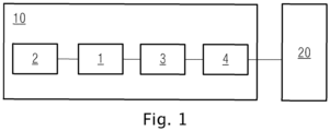
- the visual alarm device 10 comprises: a light source 1, a lens 2, a processing module 4 and a light sensing module 3; the light source 1 and the light sensing module 3 are both located on the inner side of the lens 2, and the processing module 4 is connected to the light sensing module 3; the lens 2 is constructed to transmit light emitted by the light source 1; the light sensing module 3 is used to sense the light from the lens 2 side when the light source 1 is turned on, generate an illuminance signal used to indicate the light intensity of the sensed light, and send the illuminance signal to the processing module 4; the processing module 4 is used to send a first fault signal to a management terminal 20 when it is determined that the light intensity sensed by the sensing module 3 is greater than a first illuminance threshold according to the illuminance signal, wherein the first fault signal is used to indicate that the visual
- the visual alarm device 10 in the examples of the present application comprises a light source 1, a lens 2, a processing module 4 and a light sensing module 3, wherein the light sensing module 3 can sense the light from the lens 2 side when the light source 1 is turned on, generate an illuminance signal used to indicate the light intensity of the sensed light, and send the illuminance signal to the processing module 4, the processing module 4 can send a first fault signal to a management terminal 20 when it is determined that the light intensity of the light sensed by the light sensing module 3 is greater than a first illuminance threshold according to the illuminance signal, and the first fault signal can be used to indicate that the visual alarm device is blocked; thus, the visual alarm device in the examples of the present application can realize effective feedback to the management terminal when it is blocked by dust, a coating or other objects on its surface, and the operator can know the status of the visual alarm device being blocked through the management terminal, and is thus able to accurately locate blocked visual alarm devices during inspection of the devices, without the need to check each of a large number
- the light from the lens 2 side comprises at least one of the following: light reflected from the inner surface of the lens 2, light emitted from the outer surface of the lens 2, and light transmitted from the outer side of the lens 2 to the inner side of the lens 2.
- the light emitted by the light source 1 through the lens 2 is reflected by the obstacle, and the reflected light is transmitted from the outer side of the lens 2 to the inner side of the lens 2, thereby increasing the intensity of the light sensed by the light sensing module 3, and thus the light intensity of the light sensed by the light sensing module 3 can also indicate whether the lens 2 is blocked by an external obstacle.
- the light from the lens 2 side comprises the light reflected by the inner surface of the lens 2, the light reflected by the outer surface of the lens 2, and the light transmitted from the outer side of the lens 2 to the inner side of the lens 2, and therefore the intensity of the light sensed by the light sensing module 3 can indicate soiling on the surface of the lens 2, damage to the lens 2, blocking of the lens 2 by external obstacles, etc., thereby improving the accuracy of fault detection of the visual alarm device 10.
- the light source 1 of the visual alarm device 10 may be a light-emitting element arranged on the inner side of the lens 2, and the specific configuration is not limited here.
- the light source 1 comprises LED lamps or LED lamp arrays.
- the light source 1 emits light to give an alarm.
- the light source 1 can strobe when emitting light, so that the visual alarm device 10 functions as an alarm.
- the lens 2 is used to transmit the light emitted by the light source 1.
- the specific structure and shape of the lens 2 are not limited, as long as the requirements can be met.
- the shape of the light spot formed by the light emitted by the light source 1 can be adjusted by adjusting the lens 2, and thus the visual alarm effect of the visual alarm device 10 can be adjusted with different structures of the lens 2 or different installation methods of the lens 2.
- the light sensing module 3 may comprise one or more light sensing elements, which can sense the light from the lens 2 side when the light source 1 is turned on.
- the state in which the light source 1 is turned on refers to the state in which the light source 1 emits light to the outside.
- the light reflected by the lens 2 may refer to the part of the light emitted by the light source 1 that reaches a surface of the lens 2 (for example, the inner surface and the outer surface of the lens 2) and is reflected by the surface of the lens 2 when the light source 1 is turned on;
- the light transmitted to the inner side of the lens 2 may refer to the part of light that firstly passes through the lens 2 from the inside to the outside to reach an external object and is then reflected back by the surface of the external object and transmitted to the inner side of the lens 2 from the outside to the inside when the light source 1 is turned on, wherein the external object may be, for example, dust attached to the visual alarm device 10, a coating on the visual alarm device 10, or another object that blocks the visual alarm device 10, as described previously.
- the light sensing module 3 can generate an illuminance signal used to indicate the light intensity of the sensed light.
- illuminance also known as light intensity, refers to the luminous flux received per unit area on the surface of an illuminated object.
- the light sensing module 3 generates an illuminance signal and sends it to the processing module 4, so that the processing module 4 performs analysis and processing according to the intensity of the light sensed by the light sensing module 3 indicated by the illuminance signal.
- the processing module 4 may comprise one or more processors for data processing, which may be, for example, a CPU, an MCU, an FPGA, a DSP, etc.
- the processing module 4 receives the illuminance signal sent by the light sensing module 3, determines the light intensity of the light sensed by the light sensing module 3 according to the illuminance signal, and sends the first fault signal used to indicate that the visual alarm device 10 is blocked to the management terminal 20 when the light intensity is greater than the first illuminance threshold.
- the management terminal 20 may be a mobile phone, a computer, etc., of the operator that can be used to receive signals, so that the operator can know the status of the corresponding visual alarm device 10 being blocked.
- the light intensity (for example, marked as the first light intensity) indicated by the illuminance signal generated by the light sensing module 3 is generally much higher than the light intensity (for example, marked as the second light intensity) indicated by an illuminance signal generated by the light sensing module 3 of a visual alarm device 10 that is not blocked by an external object.
- the processing module 4 can determine more accurately whether a visual alarm device 10 is blocked by comparing the first illuminance threshold with the light intensity of the light sensed by the light sensing module 3 which is determined according to the illuminance signal.
- first illuminance threshold may be configured as required, and the first illuminance threshold may be different for different visual alarm devices; this is not limited in the examples of the present application in any manner.
- the first fault signal may be sent to the management terminal 20 by the processing module 4 in the form of a character string, as long as it can indicate that the visual alarm device 10 is blocked; this is not limited by the present application.
- the first fault signal may be manifested as: "Optical failure", “Blocked”, “Visual alarm device blocked”, etc.
- the visual alarm device 10 in the present application realizes effective feedback to the management terminal 20 when the visual alarm device 10 is blocked by dust, a coating or other objects on its surface, and the operator can know the status of the visual alarm device 10 being blocked through the management terminal 20, and is thus able to accurately locate blocked visual alarm devices during inspection of the devices, without the need to check each of a large number of visual alarm devices, thereby preventing wasting of the operator's time; for visual alarm devices installed at special locations (for example, at height), the operator can inspect the devices without the need for other tools (for example, ladders, lifting equipment, etc.), thereby improving user experience of visual alarm devices; in addition, since the examples of the present application can facilitate accurate determination, by the operator, of whether a visual alarm device is blocked, it is also easy for the operator to take timely actions for the visual alarm devices that cannot send an alarm because they are blocked, thereby ensuring the alarm effect of the visual alarm devices 10.
- the processing module 4 of the visual alarm device 10 is also used to send a second fault signal to the management terminal 20 when it is determined that the light intensity sensed by the sensing module 3 is smaller than a second illuminance threshold according to the illuminance signal, wherein the second illuminance threshold is smaller than the first illuminance threshold, and the second fault signal is used to indicate that the light source 1 is faulty.
- the light intensity (for example, marked as the first light intensity) indicated by the illuminance signal generated by the light sensing module 3 is generally much lower than the light intensity (for example, marked as the second light intensity) indicated by an illuminance signal generated by the light sensing module 3 of a visual alarm device 10 whose light source 1 has not failed.
- the processing module 4 can determine more accurately whether the light source 1 of a visual alarm device 10 has failed by comparing the second illuminance threshold with the light intensity of the light sensed by the light sensing module 3 which is determined according to the illuminance signal.
- the second illuminance threshold may be configured as required, and the second illuminance threshold may be different for different visual alarm devices 10 and different light sources 1; this is not limited in the examples of the present application in any manner.
- the second fault signal may be sent to the management terminal 20 by the processing module 4 in the form of a character string, as long as it can indicate that the light source 1 is faulty; this is not limited by the present application.
- the second fault signal may be manifested as: "Light source failure”, “LED failure”, “External circuit failure”, etc.
- the light sensing module 3 of the visual alarm device 10 comprises: at least two light sensors 31; the at least two light sensors 31 are arranged at different positions on the inner side of the lens 2, and the at least two light sensors 31 are respectively connected to the processing module 4; the at least two light sensors 31 are used to respectively sense light from the lens 2 side when the light source 1 is turned on, generate an illuminance signal used to indicate the light intensity of the sensed light, and send the generated illuminance signal to the processing module 4; the processing module 4 is used to send the first fault signal to the management terminal 20 when the light intensity indicated by the illuminance signal sent by at least one of the light sensors 31 is greater than the first illuminance threshold, and send the second fault signal to the management terminal 20 when the light intensities indicated by the illuminance signals sent by both of the light sensors 31 are smaller than the second
- the type of the light sensors 31 is not limited in any manner in the examples of the present application.
- the light sensors 31 may comprise at least one light sensing element described previously.
- the processing module 4 can accurately send the first fault signal or the second fault signal to the management terminal 20 according to the light intensity indicated by the illuminance signal, thereby accurately feeding back to the management terminal 20 the result that the visual alarm device 10 is blocked or the light source 1 is faulty, so that the operator can take actions for the visual alarm device 10 in time to ensure the alarm effect of the visual alarm device 10.
- the specific composition and structure of the lens 2 are not limited, and the specific positions of the at least two light sensors 31 on the inner side of the lens 2 are not limited either, as long as the requirements can be met.
- the outer side of the lens 2 of the visual alarm device 10 is a convex surface
- the inner side of the lens 2 is provided with a cross-shaped concave portion 21
- the concave portion 21 comprises a first groove 211 and a second groove 212 that are orthogonal
- the light source 1 is arranged in a cavity 213 where the first groove 211 and the second groove 212 intersect
- the inner side of the lens 2 comprises four refraction regions 214 located between the first groove 211 and the second groove 212, and each of the refraction regions 214 is provided with at least one of the light sensors 31.
- the outer side of the lens 2 may be the side of the lens 2 remote from the light source 1, and the inner side of the lens 2 may be the side close to the light source 1.
- the sizes of the orthogonal first groove 211 and second groove 212 may be the same in some examples, and may also be different in other examples; this is not particularly limited here.
- the accuracy of the light sensor 31 sensing the light from the lens 2 side when the light source 1 is turned on can be better ensured, so that the generated illuminance signal can accurately indicate the intensity of the light, so that the processing module 4 can make a decision according to the illuminance signal and give accurate feedback to the management terminal 20.
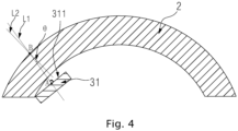
- one of the light sensors 31 is arranged on each of the refraction regions 214, and the light sensing surface 311 of the light sensors 31 faces the outside of the lens 2; for each of the light sensors 31, the angle ⁇ between the vertical line passing through the center of the light sensing surface 311 of the light sensor 31 and perpendicular to the light sensing surface 311 and the normal at the point of intersection where the vertical line and the outer surface of the lens 2 intersect is less than 15°.
- the light sensing surface 311 of the light sensors 31 faces the outside of the lens 2, so that the light sensing surface 311 can sense the light from the lens 2 side when the light source 1 is turned on.
- the angle between the vertical line passing through the center of the light sensing surface of the light sensor 31 and perpendicular to the light sensing surface and the normal at the intersection between the vertical line and the outer surface of the lens 2 is equal to 0°, i.e. the vertical line coincides with the normal.
- the accuracy of light sensing by the light sensing surface 311 of the light sensor 31 is improved, so that the generated illuminance signal can accurately indicate the intensity of the light, so that the processing module 4 can make a decision according to the illuminance signal and give accurate feedback to the management terminal 20.
- the light source 1 and the light sensor 31 are both arranged on a printed circuit board 5, the printed circuit board 5 is perpendicular to the central axis of the lens 2, the light sensing surface of the light sensor 31 is parallel to the printed circuit board 5, and the light sensor 31 is arranged at a position farther away from the light source 1, for example, at the edge region of the printed circuit board 5.
- the light source 1 and the light sensor 31 are both arranged on a printed circuit board 5, the printed circuit board 5 is perpendicular to the central axis of the lens 2, and the light sensing surface of the light sensor 31 is parallel to the printed circuit board 5, which can reduce blocking, by the light sensor 31, of the light emitted by the light source 1 and ensure the alarm effect of the visual alarm device 10.
- the light sensor 31 is arranged at a position farther away from the light source 1 to prevent or reduce perpendicular incidence of the light emitted by the light source 1 onto the light sensing surface of the light sensor 31, thereby ensuring the accuracy of detecting whether the visual alarm device 10 is blocked.
- each light sensor 31 there may be a plurality of the light sensors 31, and the light sensing surface of each light sensor 31 is parallel to the printed circuit board 5.
- the printed circuit board 5 is used to supply power to the light source 1 and each of the light sensors 31, transmit communication data between the light sensors 31 and the processing module 4, and fix the light source 1 and each of the light sensors 31.
- the light sensing module 3 in the visual alarm device 10 comprises: an annular light sensor; the light source 1 is arranged in the annular ring of the annular light sensor, and the light sensing surface of the annular light sensor faces the outside of the lens 2.
- the light sensing surface of the annular light sensors faces the outside of the lens 2, so that it can sense the light from the lens 2 side when the light source 1 is turned on.
- the light sensing module 3 uses an annular light sensor to sense light, and the sensed light is more uniform, so that the illuminance signal generated by the light sensing module 3 can more accurately indicate the intensity of the sensed light.
- the light source 1 is arranged in the annular ring of the annular light sensor, the internal structure of the visual alarm device 10 in the examples of the present application is more compact, the space utilization is more reasonable, and the overall structure is more stable.
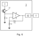
- the light sensing module 3 comprises: a DC power supply V, a light sensor 31, an operational amplifier F, a first resistor R1, a second resistor R2, a third resistor R3 and an analog-to-digital converter AD;
- the DC power supply V is connected to the input terminal of the light sensor 31, the output terminal of the light sensor 31 is connected to the input terminal of the first resistor R1, and the output terminal of the first resistor R1 is grounded;
- the non-inverting input terminal of the operational amplifier F is connected to the output terminal of the light sensor 31, the inverting input terminal of the operational amplifier F is connected to the input terminal of the second resistor R2, and the output terminal of the second resistor R2 is grounded;
- the input terminal of the third resistor R3 is connected to the output terminal of the operational amplifier F, and the output terminal of the third resistor R3 is connected to the input terminal
- the light sensor 31 may comprise an element whose resistance changes based on the intensity of the sensed light, for example, a photoresistor, a phototransistor, etc. in some examples.
- a photoresistor for example, a photoresistor, a phototransistor, etc.
- this shows an example where the light sensor 31 is a phototransistor (the specific model is not limited here, e.g. it may be a TEMT6000 photosensitive sensor in one example), but it should be understood that the present application is not limited thereto.
- the voltage at its output terminal will also change accordingly, and there is a corresponding relationship between the voltage at the output terminal and the intensity of the light, so that the voltage at the output terminal can be used to measure the intensity of the light.
- the operational amplifier F, the second resistor R2 and the third resistor R3 form an amplifying circuit, which can amplify the voltage at the output terminal and then input it into the analog-to-digital converter AD for analog-to-digital conversion.
- the analog voltage signal is converted into a digital signal, there is also a corresponding relationship between the digital signal and analog voltage signal.
- the light sensor 31 can generate an illuminance signal based on the digital signal, and therefore the illuminance signal can accurately indicate the intensity of the light.
- the operational amplifier F, the second resistor R2 and the third resistor R3 form an amplifying circuit to amplify the voltage at the output terminal, so that the analog-to-digital converter AD can perform analog-to-digital conversion more accurately, thereby ensuring that the illuminance signal generated by the light sensor 31 can accurately indicate the intensity of the light.
- the processing module 4 can accurately feed back the result that the visual alarm device 10 is blocked (or the light source 1 is faulty) to the management terminal 20, so that the operator can take actions for the visual alarm device 10 in time to ensure the alarm effect of the visual alarm device 10.
- the visual alarm device 10 in the examples of the present application comprises a light source 1, a lens 2, a processing module 4 and a light sensing module 3, wherein the light sensing module 3 can sense the light from the lens 2 side when the light source 1 is turned on, generate an illuminance signal used to indicate the light intensity of the sensed light, and send the illuminance signal to the processing module 4, the processing module 4 can send a first fault signal to a management terminal 20 when it is determined that the light intensity of the light sensed by the light sensing module 3 is greater than a first illuminance threshold according to the illuminance signal, and the first fault signal can be used to indicate that the visual alarm device is blocked, and therefore, the visual alarm device in the examples of the present application can realize effective feedback to the management terminal when it is blocked by dust, a coating or other objects on its surface, and the operator can know the status of the visual alarm device being blocked through the management terminal, and is thus able to accurately locate blocked visual alarm devices during inspection of the devices, without the
- a method for detecting a visual alarm device used to detect whether a visual alarm device is blocked, the visual alarm device comprising a light source and a lens, the light source being located on the inner side of the lens, and the method for detecting a visual alarm device comprising S101 and S102, being specifically:
- the method for detecting a visual alarm device further comprises: sending a second fault signal to the management terminal when it is determined that the light intensity of the light from the lens side is smaller than a second illuminance threshold according to the illuminance signal, wherein the second illuminance threshold is smaller than the first illuminance threshold, and the second fault signal is used to indicate that the light source is faulty.
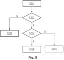
- the method comprises: S201: obtaining an illuminance signal used to indicate the light intensity of light from the lens side when the light source is turned on.
- S202 determining whether the light intensity of the light from the lens side is greater than or equal to a second illuminance threshold according to the illuminance signal, wherein, if the answer is no, S203 is performed; if yes, S204 is performed.
- S203 sending a second fault signal to a management terminal, wherein the second illuminance threshold is smaller than the first illuminance threshold, and the second fault signal is used to indicate that the light source is faulty.
- the second fault signal may be manifested as: “Light source failure”, “LED failure”, “External circuit failure”, etc.
- S204 determining whether the light intensity of the light from the lens side is smaller than or equal to the first illuminance threshold according to the illuminance signal, wherein, if the answer is no, S205 is performed; if yes, S206 is performed.
- the first fault signal may be manifested as: “Optical failure”, “Blocked”, “Visual alarm device blocked”, etc.
- the signal used to indicate that the visual alarm device is normal may be manifested as: “Normal”, “Visual alarm device normal”, etc.
- an illuminance signal used to indicate the intensity of the light from the lens side when the light source is turned on can be obtained, and a first fault signal can be sent to a management terminal when it is determined that the light intensity of the light from the lens side is greater than a first illuminance threshold according to the illuminance signal, and the first fault signal can be used to indicate that the visual alarm device is blocked, and therefore, when detecting whether a visual alarm device is blocked, effective feedback to the management terminal can be realized, so that the operator can know the status of the corresponding visual alarm device being blocked through the management terminal, and is thus able to accurately locate blocked visual alarm devices during inspection of the devices, without the need to check each of a large number of visual alarm devices, thereby preventing wasting of the operator's time; for visual alarm devices installed at special locations (for example, at height), the operator can inspect the devices without the need for other tools (for example, ladders, lifting equipment,
- Figure 9 is a schematic diagram of an electronic device provided by the examples of the present application.
- the electronic device 400 provided by the examples of the present application comprises: a processor 402, a communication interface 404, a memory 406, and a communication bus 408.
- the processor 402, the communication interface 404 and the memory 406 communicate with each other via the communication bus 408.
- the communication interface 404 is used for communicating with other electronic devices or servers.
- the processor 402 is configured to execute the program 410, specifically, to execute the relevant steps in any of the examples of the method for detecting a visual alarm device described above.
- the program 410 may comprise program code, which comprises computer operation instructions.
- the processor 402 may be a central processing unit (CPU), or an application specific integrated circuit (ASIC), or one or more integrated circuits configured to implement the examples of the present application.
- One or more processors comprised in the smart device may be of the same type, for example, one or more CPUs; or of different types, for example, one or more CPUs and one or more ASICs.
- the memory 406 is used to store a computer program 410.
- the memory 406 may comprise a high-speed RAM, and may further comprise a non-volatile memory, for example, at least one disk memory.
- the program 410 may specifically be used to cause the processor 402 to execute the method for detecting a visual alarm device in any of the examples described above.
- the examples of the present application also provide a computer-readable storage medium, which stores instructions for causing a machine to execute the method for detecting a visual alarm device as described herein.
- a system or apparatus equipped with a storage medium may be provided; software program code realizing functions of any one of the embodiments above is stored on the storage medium, and a computer (or CPU or MPU) of the system or apparatus is caused to read and execute program code stored in the storage medium.
- the program code read from the storage medium can implement the functions of any of the examples described above, and therefore the program code and the storage medium storing the program code constitute part of the present application.
- Examples of storage media used for providing program code include floppy disks, hard disks, magneto-optical disks, optical disks (such as CD-ROM, CD-R, CD-RW, DVD-ROM, DVD-RAM, DVD-RW, DVD+RW), magnetic tapes, non-volatile memory cards and ROM.
- program code may be downloaded from a server computer via a communication network.
- an operating system operating on a computer can be made to complete a portion of or all actual operations, not only through execution of program code read by a computer, but also by means of instructions based on program code, so as to realize functions of any one of the embodiments above.
- the program code read from the storage medium is written into a memory provided on an expansion board inserted into a computer or written into a memory provided in an expansion module connected to a computer, and then based on the instruction of the program code, the CPU, etc., installed on the expansion board or the expansion module performs part or all of the actual operations, thereby implementing the functions of any of the examples described above.
- the examples of the present application also provide a computer program product, which is tangibly stored on a computer-readable medium and comprises a computer-executable instruction which, when executed, causes at least one processor to perform the method for detecting a visual alarm device provided by each of the examples described above. It should be understood that the solutions in this example have the corresponding technical effects in the method examples described above, which will not be detailed here.
- a hardware module may be realized in a mechanical or an electrical manner.
- a hardware module may comprise permanently dedicated circuitry or logic (for example, a dedicated processor, an FPGA, or an ASIC) to perform the corresponding operations.
- the hardware module may further comprise programmable logic or circuitry (for example, a general-purpose processor or other programmable processors), which may be temporarily configured by software to complete the corresponding operations.
- programmable logic or circuitry for example, a general-purpose processor or other programmable processors
- Particular embodiments mechanical, or dedicated permanent circuitry, or temporarily set circuitry
Landscapes
- Physics & Mathematics (AREA)
- General Physics & Mathematics (AREA)
- Engineering & Computer Science (AREA)
- Computer Security & Cryptography (AREA)
- Electromagnetism (AREA)
- Photometry And Measurement Of Optical Pulse Characteristics (AREA)
- Fire-Detection Mechanisms (AREA)
Abstract
Description
- The present application relates to the technical field of fire protection, and in particular to a visual alarm device, a method for detecting a visual alarm device, an electronic device and a storage medium.
- Visual alarm devices are a kind of fire alarm equipment. When a fire occurs, a visual alarm device flashes to alert people to escape and evacuate. It is an important way for hearing-impaired people to obtain fire alarm information. Visual alarm devices are usually installed on the ceiling or walls, and may be blocked during use, resulting in failure of the flashing light to provide an effective warning. For example, dust, coatings or other objects on visual alarm devices will affect the alarm effect of the devices. Therefore, it is necessary to test visual alarm devices to determine whether they can send alarms normally.
- At present, it is necessary for the operator to regularly go to the sites to inspect visual alarm devices, and check each device one by one to see if it is blocked, to ensure that all the visual alarm devices can give an effective alarm when a fire occurs.
- However, since a large number of visual alarm devices are installed in large buildings such as factories, shopping malls, office buildings, etc., it takes a long time for the operator to inspect each device in the field, and it is necessary to use ladders, lifting equipment, etc., to complete the inspection of devices installed at height, resulting in poor user experience of visual alarm devices.
- In view of the above, the visual alarm device, method for detecting a visual alarm device, electronic device and storage medium provided by the present application can improve user experience of visual alarm devices.
- According to a first aspect of the embodiments of the present application, a visual alarm device is provided, comprising: a light source, a lens, a processing module and a light sensing module; the light source and the light sensing module are both located on an inner side of the lens, and the processing module is connected to the light sensing module; the lens is constructed to transmit light emitted by the light source; the light sensing module is used to sense the light from the lens side when the light source is turned on, generate an illuminance signal used to indicate the light intensity of the sensed light, and send the illuminance signal to the processing module; the processing module is used to send a first fault signal to a management terminal when it is determined that the light intensity sensed by the sensing module is greater than a first illuminance threshold according to the illuminance signal, wherein the first fault signal is used to indicate that the visual alarm device is blocked.
- In a possible embodiment, the light from the lens side comprises at least one of: light reflected from an inner surface of the lens, light emitted from an outer surface of the lens, and light transmitted from an outer side of the lens to the inner side of the lens.
- In some optional examples, the processing module is also used to send a second fault signal to the management terminal when it is determined that the light intensity sensed by the sensing module is smaller than a second illuminance threshold according to the illuminance signal, wherein the second illuminance threshold is smaller than the first illuminance threshold, and the second fault signal is used to indicate that the light source is faulty.
- In some optional examples, the light sensing module comprises: at least two light sensors; the at least two light sensors are arranged at different positions on the inner side of the lens, and the at least two light sensors are respectively connected to the processing module; the at least two light sensors are used to respectively sense light from the lens side when the light source is turned on, generate an illuminance signal used to indicate a light intensity of the sensed light, and send the generated illuminance signal to the processing module; the processing module is used to send the first fault signal to the management terminal when the light intensity indicated by the illuminance signal sent by at least one of the light sensors is greater than the first illuminance threshold, and send the second fault signal to the management terminal when the light intensities indicated by the illuminance signals sent by both of the light sensors are smaller than the second illuminance threshold.
- In some optional examples, the outer side of the lens is a convex surface, the inner side of the lens is provided with a cross-shaped concave portion, the concave portion comprises a first groove and a second groove that are orthogonal, and the light source is arranged in a cavity where the first groove and the second groove intersect; the inner side of the lens comprises four refraction regions located between the first groove and the second groove, and each of the refraction regions is provided with at least one of the light sensors.
- In some optional examples, one of the light sensors is arranged on each of the refraction regions, and a light sensing surface of the light sensors faces the outer side of the lens; for each of the light sensors, the angle between the vertical line passing through the center of the light sensing surface of the light sensor and perpendicular to the light sensing surface and the normal at the point of intersection where the vertical line and the outer surface of the lens intersect is less than 15°.
- In some optional examples, the light sensing module comprises: an annular light sensor; the light source is arranged in the annular ring of the annular light sensor, and a light sensing surface of the annular light sensor faces the outer side of the lens.
- In some optional examples, the light sensing module comprises: a DC power supply, a light sensor, an operational amplifier, a first resistor, a second resistor, a third resistor and an analog-to-digital converter; the DC power supply is connected to the input terminal of the light sensor, the output terminal of the light sensor is connected to the input terminal of the first resistor, and the output terminal of the first resistor is grounded; the non-inverting input terminal of the operational amplifier is connected to the output terminal of the light sensor, the inverting input terminal of the operational amplifier is connected to the input terminal of the second resistor, and the output terminal of the second resistor is grounded; the input terminal of the third resistor is connected to the output terminal of the operational amplifier, and the output terminal of the third resistor is connected to the input terminal of the second resistor; the output terminal of the operational amplifier is connected to the input terminal of the analog-to-digital converter, and the output terminal of the analog-to-digital converter is connected to the processing module.
- According to a second aspect of the present application, a method for detecting a visual alarm device is provided, used to detect whether a visual alarm device is blocked, the visual alarm device comprising a light source and a lens, the light source being located on the inner side of the lens, and the method for detecting a visual alarm device comprising: obtaining an illuminance signal used to indicate the light intensity of light from the lens side when the light source is turned on;
sending a first fault signal to a management terminal when it is determined that the light intensity of the light from the lens side is greater than a first illuminance threshold according to the illuminance signal, wherein the first fault signal is used to indicate that the visual alarm device is blocked. - In some optional examples, the method for detecting a visual alarm device further comprises: sending a second fault signal to the management terminal when it is determined that the light intensity of the light from the lens side is smaller than a second illuminance threshold according to the illuminance signal, wherein the second illuminance threshold is smaller than the first illuminance threshold, and the second fault signal is used to indicate that the light source is faulty.
- According to a third aspect of the present application, an electronic device is provided, comprising: a processor, a communication interface, a memory, and a communication bus, the processor, the memory and the communication interface communicating with each other via the communication bus; the memory is used to store at least one executable instruction, and the executable instruction causes the processor to perform the operations corresponding to the method for detecting a visual alarm device provided in the first aspect described above.
- According to a fourth aspect of the present application, a computer-readable medium is provided, which has a computer program stored thereon, which, when executed by a processor, causes the processor to perform the operations corresponding to the method for detecting a visual alarm device provided in the first aspect described above.
- According to a fifth aspect of the present application, a computer program product is provided, which is tangibly stored on a computer-readable medium and comprises a computer-executable instruction which, when executed, causes at least one processor to perform the method for detecting a visual alarm device provided by the first aspect or any of the possible embodiments of the first aspect described above.
- In the above technical solution, the visual alarm device in the examples of the present application comprises a light source, a lens, a processing module and a light sensing module, the light sensing module can sense the light from the lens side when the light source is turned on, generate an illuminance signal used to indicate the light intensity of the sensed light, and send the illuminance signal to the processing module, and the processing module can send a first fault signal to a management terminal when it is determined that the light intensity of the light sensed by the light sensing module is greater than a first illuminance threshold according to the illuminance signal, and the first fault signal can be used to indicate that the visual alarm device is blocked. In this way, the visual alarm device in the examples of the present application can realize effective feedback to the management terminal when it is blocked by dust, a coating or other objects on its surface, so that an operator can know the status of the visual alarm device being blocked through the management terminal, and is thus able to accurately locate blocked visual alarm devices during inspection of the devices, without the need to check each of a large number of visual alarm devices, thereby preventing wasting of the operator's time; for visual alarm devices installed at special locations (for example, at height), the operator can inspect the devices without the need for other tools (for example, ladders, lifting equipment, etc.), thereby improving user experience of visual alarm devices; in addition, since the examples of the present application can facilitate accurate determination, by an operator, of whether a visual alarm device is blocked, it is also easy for the operator to take timely actions for the visual alarm devices that cannot send an alarm because they are blocked, thereby ensuring the alarm effect of the visual alarm devices.
-
- Figure 1
- is a schematic diagram of a visual alarm device provided by the examples of the present application;
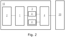
- Figure 2
- is a schematic diagram of another visual alarm device provided by the examples of the present application;
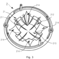
- Figure 3
- is a schematic diagram of a lens provided by the examples of the present application;
- Figure 4
- is a schematic diagram of relative positions of the light sensor and the lens provided by the examples of the present application;
- Figure 5
- is a schematic diagram of relative positions of the light sensor of another type and the lens provided by the examples of the present application;
- Figure 6
- is a schematic structural diagram of the circuit of a light sensing module provided by the examples of the present application;
- Figure 7
- is a flowchart of a method for detecting a visual alarm device provided by the examples of the present application;
- Figure 8
- is a flowchart of another method for detecting a visual alarm device provided by the examples of the present application;
- Figure 9
- is a schematic diagram of an electronic device provided by the examples of the present application.
-
10: Visual alarm device 20: Management terminal 1: Light source 2: Lens 3: Processing module 4: Light sensing module 31: Light sensor 21: Concave portion 211: First groove 212: Second groove 213: Cavity 214: Refraction region 311: Light sensing V: DC power supply F: Operational surface amplifier R1: First resistor R2: Second resistor R3: Third resistor AD: Analog-to-converter digital 400: Electronic device 402: Processor 404: Communication interface 406: Memory 408: Communication bus 410: Program θ: Angle 5: Printed circuit board - S101: obtaining an illuminance signal used to indicate the light intensity of light from the lens side when the light source is turned on
- S102: sending a first fault signal to a management terminal when it is determined that the light intensity of the light from the lens side is greater than a first illuminance threshold according to the illuminance signal
- S201: obtaining an illuminance signal used to indicate the light intensity of light from the lens side when the light source is turned on
- S202: determining whether the light intensity of the light from the lens side is greater than or equal to a second illuminance threshold according to the illuminance signal
- S203: sending a second fault signal to the management terminal
- S204: determining whether the light intensity of the light from the lens side is smaller than or equal to a first illuminance threshold according to the illuminance signal
- S205: sending a first fault signal to a management terminal, wherein the first fault signal is used to indicate that the visual alarm device is blocked
- S206: sending a signal used to indicate that the visual alarm device is working normally to the management terminal
- As described previously, visual alarm devices are a kind of fire alarm equipment. When a fire occurs, a visual alarm device flashes to alert people to escape and evacuate. It is an important way for hearing-impaired people to obtain fire alarm information. Visual alarm devices are usually installed on the ceiling or walls, and may be blocked during use, resulting in failure of the emitted flashing light to provide an effective warning. For example, dust, coatings or other objects on visual alarm devices will affect the alarm effect of the devices. Therefore, it is necessary to test visual alarm devices to determine whether they can send alarms normally. At present, it is necessary for the operator to regularly go to the sites to inspect visual alarm devices, and check each device one by one to see if it is blocked, to ensure that all the visual alarm devices can give an effective alarm when a fire occurs. However, since a large number of visual alarm devices are installed in large buildings such as factories, shopping malls, office buildings, etc., it takes a long time for the operator to inspect each device in the field, and it is necessary to use ladders, lifting equipment, etc., to complete the inspection of devices installed at height, resulting in poor user experience of visual alarm devices.
- In view of this, with reference to
Figure 1 , in a first aspect of the examples of the present application, avisual alarm device 10 is provided, which can at least partially solve the above problem. Thevisual alarm device 10 comprises: alight source 1, alens 2, aprocessing module 4 and alight sensing module 3; thelight source 1 and thelight sensing module 3 are both located on the inner side of thelens 2, and theprocessing module 4 is connected to thelight sensing module 3; thelens 2 is constructed to transmit light emitted by thelight source 1; thelight sensing module 3 is used to sense the light from thelens 2 side when thelight source 1 is turned on, generate an illuminance signal used to indicate the light intensity of the sensed light, and send the illuminance signal to theprocessing module 4; theprocessing module 4 is used to send a first fault signal to amanagement terminal 20 when it is determined that the light intensity sensed by thesensing module 3 is greater than a first illuminance threshold according to the illuminance signal, wherein the first fault signal is used to indicate that thevisual alarm device 10 is blocked. - The visual alarm device 10 in the examples of the present application comprises a light source 1, a lens 2, a processing module 4 and a light sensing module 3, wherein the light sensing module 3 can sense the light from the lens 2 side when the light source 1 is turned on, generate an illuminance signal used to indicate the light intensity of the sensed light, and send the illuminance signal to the processing module 4, the processing module 4 can send a first fault signal to a management terminal 20 when it is determined that the light intensity of the light sensed by the light sensing module 3 is greater than a first illuminance threshold according to the illuminance signal, and the first fault signal can be used to indicate that the visual alarm device is blocked; thus, the visual alarm device in the examples of the present application can realize effective feedback to the management terminal when it is blocked by dust, a coating or other objects on its surface, and the operator can know the status of the visual alarm device being blocked through the management terminal, and is thus able to accurately locate blocked visual alarm devices during inspection of the devices, without the need to check each of a large number of visual alarm devices, thereby preventing wasting of the operator's time; for visual alarm devices installed at special locations (for example, at height), the operator can inspect the devices without the need for other tools (for example, ladders, lifting equipment, etc.), thereby improving user experience of visual alarm devices; in addition, since the examples of the present application can facilitate accurate determination, by an operator, of whether a visual alarm device is blocked, it is also easy for the operator to take timely actions for the visual alarm devices that cannot send an alarm because they are blocked, thereby ensuring the alarm effect of the visual alarm devices.
- In a possible embodiment, the light from the
lens 2 side comprises at least one of the following: light reflected from the inner surface of thelens 2, light emitted from the outer surface of thelens 2, and light transmitted from the outer side of thelens 2 to the inner side of thelens 2. - The
light source 1 is located on the inner side of thelens 2. When the light emitted by thelight source 1 passes through thelens 2, the inner and outer surfaces of thelens 2 will both reflect the light emitted by thelight source 1, and the amount of the reflected light can indicate the light transmission of thelens 2. For example, when the outer surface of thelens 2 is dirty or thelens 2 is damaged, the amount of light transmitted by thelens 2 will be reduced, thereby reducing the light reflected by thelens 2 to thelight sensing module 3. When an obstacle, for example, a wardrobe, at the outer side of thelens 2 blocks thevisual alarm device 10, the light emitted by thelight source 1 through thelens 2 is reflected by the obstacle, and the reflected light is transmitted from the outer side of thelens 2 to the inner side of thelens 2, thereby increasing the intensity of the light sensed by thelight sensing module 3, and thus the light intensity of the light sensed by thelight sensing module 3 can also indicate whether thelens 2 is blocked by an external obstacle. - In the examples of the present application, the light from the
lens 2 side comprises the light reflected by the inner surface of thelens 2, the light reflected by the outer surface of thelens 2, and the light transmitted from the outer side of thelens 2 to the inner side of thelens 2, and therefore the intensity of the light sensed by thelight sensing module 3 can indicate soiling on the surface of thelens 2, damage to thelens 2, blocking of thelens 2 by external obstacles, etc., thereby improving the accuracy of fault detection of thevisual alarm device 10. - The
visual alarm device 10 provided in the examples of the present application will be described in detail below in conjunction with the drawings. It should be understood that the description below is not intended as any limitation in the examples of the present application. - In the examples of the present application, the
light source 1 of thevisual alarm device 10 may be a light-emitting element arranged on the inner side of thelens 2, and the specific configuration is not limited here. For example, in some examples, thelight source 1 comprises LED lamps or LED lamp arrays. When a situation that needs an alarm to be sent occurs during the operation of thevisual alarm device 10, thelight source 1 emits light to give an alarm. For example, thelight source 1 can strobe when emitting light, so that thevisual alarm device 10 functions as an alarm. - The
lens 2 is used to transmit the light emitted by thelight source 1. In the examples of the present application, the specific structure and shape of thelens 2 are not limited, as long as the requirements can be met. When the light emitted by thelight source 1 is output through thelens 2, the shape of the light spot formed by the light emitted by thelight source 1 can be adjusted by adjusting thelens 2, and thus the visual alarm effect of thevisual alarm device 10 can be adjusted with different structures of thelens 2 or different installation methods of thelens 2. - The specific structure of the
light sensing module 3 is not limited in the examples of the application. For example, thelight sensing module 3 may comprise one or more light sensing elements, which can sense the light from thelens 2 side when thelight source 1 is turned on. - It can be understood that the state in which the
light source 1 is turned on refers to the state in which thelight source 1 emits light to the outside. Specifically, the light reflected by thelens 2 may refer to the part of the light emitted by thelight source 1 that reaches a surface of the lens 2 (for example, the inner surface and the outer surface of the lens 2) and is reflected by the surface of thelens 2 when thelight source 1 is turned on; the light transmitted to the inner side of thelens 2 may refer to the part of light that firstly passes through thelens 2 from the inside to the outside to reach an external object and is then reflected back by the surface of the external object and transmitted to the inner side of thelens 2 from the outside to the inside when thelight source 1 is turned on, wherein the external object may be, for example, dust attached to thevisual alarm device 10, a coating on thevisual alarm device 10, or another object that blocks thevisual alarm device 10, as described previously. - After sensing the light from the
lens 2 side when thelight source 1 is turned on, thelight sensing module 3 can generate an illuminance signal used to indicate the light intensity of the sensed light. In optics, illuminance, also known as light intensity, refers to the luminous flux received per unit area on the surface of an illuminated object. In the examples of the present application, thelight sensing module 3 generates an illuminance signal and sends it to theprocessing module 4, so that theprocessing module 4 performs analysis and processing according to the intensity of the light sensed by thelight sensing module 3 indicated by the illuminance signal. - In the examples of the present application, the
processing module 4 may comprise one or more processors for data processing, which may be, for example, a CPU, an MCU, an FPGA, a DSP, etc. Theprocessing module 4 receives the illuminance signal sent by thelight sensing module 3, determines the light intensity of the light sensed by thelight sensing module 3 according to the illuminance signal, and sends the first fault signal used to indicate that thevisual alarm device 10 is blocked to themanagement terminal 20 when the light intensity is greater than the first illuminance threshold. For example, themanagement terminal 20 may be a mobile phone, a computer, etc., of the operator that can be used to receive signals, so that the operator can know the status of the correspondingvisual alarm device 10 being blocked. - Specifically, for a
visual alarm device 10 that is blocked by an external object, more of the light emitted by thelight source 1 will be reflected to the inside of thelens 2 by the external object, i.e. more light will be transmitted to the inner side of thelens 2, and as a result, the light intensity (for example, marked as the first light intensity) indicated by the illuminance signal generated by thelight sensing module 3 is generally much higher than the light intensity (for example, marked as the second light intensity) indicated by an illuminance signal generated by thelight sensing module 3 of avisual alarm device 10 that is not blocked by an external object. Based on this, by setting a first illuminance threshold, theprocessing module 4 can determine more accurately whether avisual alarm device 10 is blocked by comparing the first illuminance threshold with the light intensity of the light sensed by thelight sensing module 3 which is determined according to the illuminance signal. - It should be noted that the first illuminance threshold may be configured as required, and the first illuminance threshold may be different for different visual alarm devices; this is not limited in the examples of the present application in any manner.
- Optionally, the first fault signal may be sent to the
management terminal 20 by theprocessing module 4 in the form of a character string, as long as it can indicate that thevisual alarm device 10 is blocked; this is not limited by the present application. For example, the first fault signal may be manifested as: "Optical failure", "Blocked", "Visual alarm device blocked", etc. - Based on this, the
visual alarm device 10 in the present application realizes effective feedback to themanagement terminal 20 when thevisual alarm device 10 is blocked by dust, a coating or other objects on its surface, and the operator can know the status of thevisual alarm device 10 being blocked through themanagement terminal 20, and is thus able to accurately locate blocked visual alarm devices during inspection of the devices, without the need to check each of a large number of visual alarm devices, thereby preventing wasting of the operator's time; for visual alarm devices installed at special locations (for example, at height), the operator can inspect the devices without the need for other tools (for example, ladders, lifting equipment, etc.), thereby improving user experience of visual alarm devices; in addition, since the examples of the present application can facilitate accurate determination, by the operator, of whether a visual alarm device is blocked, it is also easy for the operator to take timely actions for the visual alarm devices that cannot send an alarm because they are blocked, thereby ensuring the alarm effect of thevisual alarm devices 10. - In some optional examples, the
processing module 4 of thevisual alarm device 10 is also used to send a second fault signal to themanagement terminal 20 when it is determined that the light intensity sensed by thesensing module 3 is smaller than a second illuminance threshold according to the illuminance signal, wherein the second illuminance threshold is smaller than the first illuminance threshold, and the second fault signal is used to indicate that thelight source 1 is faulty. - Based on this, effective feedback can be given to the management terminal when the
light source 1 of thevisual alarm device 10 has a fault and cannot work normally, and the operator can know through themanagement terminal 20 that thelight source 1 of the correspondingvisual alarm device 10 has failed, so that timely actions can be taken to fix thelight source 1 of thevisual alarm device 10, to ensure that thevisual alarm device 10 can work normally and ensure the alarm effect of thevisual alarm device 10. - Specifically, for a
visual alarm device 10 whoselight source 1 fails, it is difficult for thelight source 1 to emit light to the outside normally, and as a result, the light intensity (for example, marked as the first light intensity) indicated by the illuminance signal generated by thelight sensing module 3 is generally much lower than the light intensity (for example, marked as the second light intensity) indicated by an illuminance signal generated by thelight sensing module 3 of avisual alarm device 10 whoselight source 1 has not failed. Based on this, by setting a second illuminance threshold, theprocessing module 4 can determine more accurately whether thelight source 1 of avisual alarm device 10 has failed by comparing the second illuminance threshold with the light intensity of the light sensed by thelight sensing module 3 which is determined according to the illuminance signal. - It should be noted that the second illuminance threshold may be configured as required, and the second illuminance threshold may be different for different
visual alarm devices 10 anddifferent light sources 1; this is not limited in the examples of the present application in any manner. - Optionally, the second fault signal may be sent to the
management terminal 20 by theprocessing module 4 in the form of a character string, as long as it can indicate that thelight source 1 is faulty; this is not limited by the present application. For example, the second fault signal may be manifested as: "Light source failure", "LED failure", "External circuit failure", etc. - In the examples of the present application, the specific composition and structure of the
light sensing module 3 are not limited, as long as the requirements can be met. Exemplarily, with reference toFigure 2 , in some optional examples, thelight sensing module 3 of thevisual alarm device 10 comprises: at least twolight sensors 31; the at least twolight sensors 31 are arranged at different positions on the inner side of thelens 2, and the at least twolight sensors 31 are respectively connected to theprocessing module 4; the at least twolight sensors 31 are used to respectively sense light from thelens 2 side when thelight source 1 is turned on, generate an illuminance signal used to indicate the light intensity of the sensed light, and send the generated illuminance signal to theprocessing module 4; theprocessing module 4 is used to send the first fault signal to themanagement terminal 20 when the light intensity indicated by the illuminance signal sent by at least one of thelight sensors 31 is greater than the first illuminance threshold, and send the second fault signal to themanagement terminal 20 when the light intensities indicated by the illuminance signals sent by both of thelight sensors 31 are smaller than the second illuminance threshold. - The type of the
light sensors 31 is not limited in any manner in the examples of the present application. For example, thelight sensors 31 may comprise at least one light sensing element described previously. - Through such a structure of the
light sensing module 3, it can be ensured that the illuminance signal generated thereby can accurately indicate the light intensity of the light sensed by thelight sensing module 3, so that theprocessing module 4 can accurately send the first fault signal or the second fault signal to themanagement terminal 20 according to the light intensity indicated by the illuminance signal, thereby accurately feeding back to themanagement terminal 20 the result that thevisual alarm device 10 is blocked or thelight source 1 is faulty, so that the operator can take actions for thevisual alarm device 10 in time to ensure the alarm effect of thevisual alarm device 10. - In the examples of the present application, the specific composition and structure of the
lens 2 are not limited, and the specific positions of the at least twolight sensors 31 on the inner side of thelens 2 are not limited either, as long as the requirements can be met. Exemplarily, with reference toFigure 3 , in some optional examples, the outer side of thelens 2 of thevisual alarm device 10 is a convex surface, the inner side of thelens 2 is provided with a cross-shapedconcave portion 21, theconcave portion 21 comprises afirst groove 211 and asecond groove 212 that are orthogonal, and thelight source 1 is arranged in acavity 213 where thefirst groove 211 and thesecond groove 212 intersect; the inner side of thelens 2 comprises fourrefraction regions 214 located between thefirst groove 211 and thesecond groove 212, and each of therefraction regions 214 is provided with at least one of thelight sensors 31. - With reference to
Figure 3 , the outer side of thelens 2 may be the side of thelens 2 remote from thelight source 1, and the inner side of thelens 2 may be the side close to thelight source 1. The sizes of the orthogonalfirst groove 211 andsecond groove 212 may be the same in some examples, and may also be different in other examples; this is not particularly limited here. - Based on such a structure, the accuracy of the
light sensor 31 sensing the light from thelens 2 side when thelight source 1 is turned on can be better ensured, so that the generated illuminance signal can accurately indicate the intensity of the light, so that theprocessing module 4 can make a decision according to the illuminance signal and give accurate feedback to themanagement terminal 20. - In some optional examples, in the
visual alarm device 10, one of thelight sensors 31 is arranged on each of therefraction regions 214, and thelight sensing surface 311 of thelight sensors 31 faces the outside of thelens 2; for each of thelight sensors 31, the angle θ between the vertical line passing through the center of thelight sensing surface 311 of thelight sensor 31 and perpendicular to thelight sensing surface 311 and the normal at the point of intersection where the vertical line and the outer surface of thelens 2 intersect is less than 15°. - Specifically, the
light sensing surface 311 of thelight sensors 31 faces the outside of thelens 2, so that thelight sensing surface 311 can sense the light from thelens 2 side when thelight source 1 is turned on. - In addition, when understood with reference to the schematic sectional diagram
Figure 4 , which schematically shows the angle θ between the vertical line L1 passing through the center A of thelight sensing surface 311 of thelight sensor 31 and perpendicular to thelight sensing surface 311 and the normal L2 at the intersection B between the vertical line L1 and the outer surface of thelens 2, when the angle θ is smaller than 15°, more of the light from thelens 2 side when thelight source 1 is turned on can be reflected to thelight sensing surface 311 of thelight sensor 31, and in this case, thelight sensing surface 311 of thelight sensor 31 can sense light more accurately, such that the generated illuminance signal can indicate the intensity of the light more accurately, so that theprocessing module 4 can make a decision according to the illuminance signal and give accurate feedback to themanagement terminal 20. - In some preferred examples, for each of the
light sensors 31, the angle between the vertical line passing through the center of the light sensing surface of thelight sensor 31 and perpendicular to the light sensing surface and the normal at the intersection between the vertical line and the outer surface of thelens 2 is equal to 0°, i.e. the vertical line coincides with the normal. In this case, the accuracy of light sensing by thelight sensing surface 311 of thelight sensor 31 is improved, so that the generated illuminance signal can accurately indicate the intensity of the light, so that theprocessing module 4 can make a decision according to the illuminance signal and give accurate feedback to themanagement terminal 20. - In a possible embodiment, as shown in
Figure 5 , thelight source 1 and thelight sensor 31 are both arranged on a printed circuit board 5, the printed circuit board 5 is perpendicular to the central axis of thelens 2, the light sensing surface of thelight sensor 31 is parallel to the printed circuit board 5, and thelight sensor 31 is arranged at a position farther away from thelight source 1, for example, at the edge region of the printed circuit board 5. - In a possible embodiment, the
light source 1 and thelight sensor 31 are both arranged on a printed circuit board 5, the printed circuit board 5 is perpendicular to the central axis of thelens 2, and the light sensing surface of thelight sensor 31 is parallel to the printed circuit board 5, which can reduce blocking, by thelight sensor 31, of the light emitted by thelight source 1 and ensure the alarm effect of thevisual alarm device 10. Thelight sensor 31 is arranged at a position farther away from thelight source 1 to prevent or reduce perpendicular incidence of the light emitted by thelight source 1 onto the light sensing surface of thelight sensor 31, thereby ensuring the accuracy of detecting whether thevisual alarm device 10 is blocked. - It should be noted that, on the basis of the
visual alarm device 10 as shown inFigure 5 , there may be a plurality of thelight sensors 31, and the light sensing surface of eachlight sensor 31 is parallel to the printed circuit board 5. The printed circuit board 5 is used to supply power to thelight source 1 and each of thelight sensors 31, transmit communication data between thelight sensors 31 and theprocessing module 4, and fix thelight source 1 and each of thelight sensors 31. - In some optional examples, the
light sensing module 3 in thevisual alarm device 10 comprises: an annular light sensor; thelight source 1 is arranged in the annular ring of the annular light sensor, and the light sensing surface of the annular light sensor faces the outside of thelens 2. - Specifically, the light sensing surface of the annular light sensors faces the outside of the
lens 2, so that it can sense the light from thelens 2 side when thelight source 1 is turned on. - In the examples of the present application, the
light sensing module 3 uses an annular light sensor to sense light, and the sensed light is more uniform, so that the illuminance signal generated by thelight sensing module 3 can more accurately indicate the intensity of the sensed light. In addition, because thelight source 1 is arranged in the annular ring of the annular light sensor, the internal structure of thevisual alarm device 10 in the examples of the present application is more compact, the space utilization is more reasonable, and the overall structure is more stable. - The circuit structure of the
light sensing module 3 is not particularly limited in the examples of the present application, as long as the function can be realized. Exemplarily, in some optional examples, with reference toFigure 6 , thelight sensing module 3 comprises: a DC power supply V, alight sensor 31, an operational amplifier F, a first resistor R1, a second resistor R2, a third resistor R3 and an analog-to-digital converter AD; the DC power supply V is connected to the input terminal of thelight sensor 31, the output terminal of thelight sensor 31 is connected to the input terminal of the first resistor R1, and the output terminal of the first resistor R1 is grounded; the non-inverting input terminal of the operational amplifier F is connected to the output terminal of thelight sensor 31, the inverting input terminal of the operational amplifier F is connected to the input terminal of the second resistor R2, and the output terminal of the second resistor R2 is grounded; the input terminal of the third resistor R3 is connected to the output terminal of the operational amplifier F, and the output terminal of the third resistor R3 is connected to the input terminal of the second resistor R2; the output terminal of the operational amplifier F is connected to the input terminal of the analog-to-digital converter AD, and the output terminal of the analog-to-digital converter AD is connected to theprocessing module 4. - Optionally, the
light sensor 31 may comprise an element whose resistance changes based on the intensity of the sensed light, for example, a photoresistor, a phototransistor, etc. in some examples. With reference toFigure 6 , this shows an example where thelight sensor 31 is a phototransistor (the specific model is not limited here, e.g. it may be a TEMT6000 photosensitive sensor in one example), but it should be understood that the present application is not limited thereto. - When the resistance value of the
light sensor 31 changes with the intensity of the light, the voltage at its output terminal will also change accordingly, and there is a corresponding relationship between the voltage at the output terminal and the intensity of the light, so that the voltage at the output terminal can be used to measure the intensity of the light. The operational amplifier F, the second resistor R2 and the third resistor R3 form an amplifying circuit, which can amplify the voltage at the output terminal and then input it into the analog-to-digital converter AD for analog-to-digital conversion. When the analog voltage signal is converted into a digital signal, there is also a corresponding relationship between the digital signal and analog voltage signal. Subsequently, thelight sensor 31 can generate an illuminance signal based on the digital signal, and therefore the illuminance signal can accurately indicate the intensity of the light. It can be understood that, since the voltage at the output terminal is generally not high, the operational amplifier F, the second resistor R2 and the third resistor R3 form an amplifying circuit to amplify the voltage at the output terminal, so that the analog-to-digital converter AD can perform analog-to-digital conversion more accurately, thereby ensuring that the illuminance signal generated by thelight sensor 31 can accurately indicate the intensity of the light. - Obviously, with such a circuit structure, since it can accurately ensure that the
light sensor 31 of thelight sensing module 3 senses the light and accurately generates an illuminance signal used to indicate the intensity of the light, theprocessing module 4 can accurately feed back the result that thevisual alarm device 10 is blocked (or thelight source 1 is faulty) to themanagement terminal 20, so that the operator can take actions for thevisual alarm device 10 in time to ensure the alarm effect of thevisual alarm device 10. - It should be understood that the above optional examples of the
visual alarm device 10 in the examples of the present application are only used as some exemplary explanations, and should not be regarded as any limitation to the examples of the present application. - It can be seen from the description above that the visual alarm device 10 in the examples of the present application comprises a light source 1, a lens 2, a processing module 4 and a light sensing module 3, wherein the light sensing module 3 can sense the light from the lens 2 side when the light source 1 is turned on, generate an illuminance signal used to indicate the light intensity of the sensed light, and send the illuminance signal to the processing module 4, the processing module 4 can send a first fault signal to a management terminal 20 when it is determined that the light intensity of the light sensed by the light sensing module 3 is greater than a first illuminance threshold according to the illuminance signal, and the first fault signal can be used to indicate that the visual alarm device is blocked, and therefore, the visual alarm device in the examples of the present application can realize effective feedback to the management terminal when it is blocked by dust, a coating or other objects on its surface, and the operator can know the status of the visual alarm device being blocked through the management terminal, and is thus able to accurately locate blocked visual alarm devices during inspection of the devices, without the need to check each of a large number of visual alarm devices, thereby preventing wasting of the operator's time; for visual alarm devices installed at special locations (for example, at height), the operator can inspect the devices without the need for other tools (for example, ladders, lifting equipment, etc.), thereby improving user experience of visual alarm devices; in addition, since the examples of the present application can facilitate accurate determination, by an operator, of whether a visual alarm device is blocked, it is also easy for the operator to take timely actions for the visual alarm devices that cannot send an alarm because they are blocked, thereby ensuring the alarm effect of the visual alarm devices.
- According to a second aspect in the examples of the present disclosure, with reference to the flowchart shown in
Figure 7 , a method for detecting a visual alarm device is provided, used to detect whether a visual alarm device is blocked, the visual alarm device comprising a light source and a lens, the light source being located on the inner side of the lens, and the method for detecting a visual alarm device comprising S101 and S102, being specifically: - S101: obtaining an illuminance signal used to indicate the light intensity of light from the lens side when the light source is turned on.
- S102: sending a first fault signal to a management terminal when it is determined that the light intensity of the light from the lens side is greater than a first illuminance threshold according to the illuminance signal, wherein the first fault signal is used to indicate that the visual alarm device is blocked.
- In some optional examples, the method for detecting a visual alarm device further comprises: sending a second fault signal to the management terminal when it is determined that the light intensity of the light from the lens side is smaller than a second illuminance threshold according to the illuminance signal, wherein the second illuminance threshold is smaller than the first illuminance threshold, and the second fault signal is used to indicate that the light source is faulty.
- Exemplarily, when understood with reference to the flowchart in
Figure 8 , which is an overall flowchart of another exemplary method for detecting a visual alarm device in the examples of the present application, the method comprises: S201: obtaining an illuminance signal used to indicate the light intensity of light from the lens side when the light source is turned on. - S202: determining whether the light intensity of the light from the lens side is greater than or equal to a second illuminance threshold according to the illuminance signal, wherein, if the answer is no, S203 is performed; if yes, S204 is performed.
- S203: sending a second fault signal to a management terminal, wherein the second illuminance threshold is smaller than the first illuminance threshold, and the second fault signal is used to indicate that the light source is faulty.
- For example, the second fault signal may be manifested as: "Light source failure", "LED failure", "External circuit failure", etc.
- S204: determining whether the light intensity of the light from the lens side is smaller than or equal to the first illuminance threshold according to the illuminance signal, wherein, if the answer is no, S205 is performed; if yes, S206 is performed.
- S205: sending a first fault signal to a management terminal, wherein the first fault signal is used to indicate that the visual alarm device is blocked.
- For example, the first fault signal may be manifested as: "Optical failure", "Blocked", "Visual alarm device blocked", etc.
- S206: sending a signal used to indicate that the visual alarm device is working normally to the management terminal.
- For example, the signal used to indicate that the visual alarm device is normal may be manifested as: "Normal", "Visual alarm device normal", etc.
- It can be seen from the description above that in the method for detecting a visual alarm device in the examples of the present application, an illuminance signal used to indicate the intensity of the light from the lens side when the light source is turned on can be obtained, and a first fault signal can be sent to a management terminal when it is determined that the light intensity of the light from the lens side is greater than a first illuminance threshold according to the illuminance signal, and the first fault signal can be used to indicate that the visual alarm device is blocked, and therefore, when detecting whether a visual alarm device is blocked, effective feedback to the management terminal can be realized, so that the operator can know the status of the corresponding visual alarm device being blocked through the management terminal, and is thus able to accurately locate blocked visual alarm devices during inspection of the devices, without the need to check each of a large number of visual alarm devices, thereby preventing wasting of the operator's time; for visual alarm devices installed at special locations (for example, at height), the operator can inspect the devices without the need for other tools (for example, ladders, lifting equipment, etc.), thereby improving user experience of visual alarm devices; in addition, since the examples of the present application can facilitate accurate determination, by an operator, of whether a visual alarm device is blocked, it is also easy for the operator to take timely actions for the visual alarm devices that cannot send an alarm because they are blocked, thereby ensuring the alarm effect of the visual alarm devices.
- It should be noted that the information interaction and execution process among the various units in the method for detecting a visual alarm device described above are based on the same idea as the product examples of the
visual alarm device 10 described previously, and the particulars and benefits can be found in the description of thevisual alarm device 10, which is not detailed here. -
Figure 9 is a schematic diagram of an electronic device provided by the examples of the present application. The specific examples of the present application do not limit the specific implementation of the electronic device. With reference toFigure 9 , theelectronic device 400 provided by the examples of the present application comprises: aprocessor 402, acommunication interface 404, amemory 406, and acommunication bus 408. Here:
Theprocessor 402, thecommunication interface 404 and thememory 406 communicate with each other via thecommunication bus 408. - The
communication interface 404 is used for communicating with other electronic devices or servers. - The
processor 402 is configured to execute theprogram 410, specifically, to execute the relevant steps in any of the examples of the method for detecting a visual alarm device described above. - Specifically, the
program 410 may comprise program code, which comprises computer operation instructions. - The
processor 402 may be a central processing unit (CPU), or an application specific integrated circuit (ASIC), or one or more integrated circuits configured to implement the examples of the present application. One or more processors comprised in the smart device may be of the same type, for example, one or more CPUs; or of different types, for example, one or more CPUs and one or more ASICs. - The
memory 406 is used to store acomputer program 410. Thememory 406 may comprise a high-speed RAM, and may further comprise a non-volatile memory, for example, at least one disk memory. - The
program 410 may specifically be used to cause theprocessor 402 to execute the method for detecting a visual alarm device in any of the examples described above. - The description of the corresponding steps and units in any of the examples of the method for detecting a visual alarm device may be referred to for the specific implementation of each step in the
program 410, which will not be detailed here. Those skilled in the art can clearly understand that, for the convenience and simplicity of the description, the corresponding process description in the method examples above may be referred to for the specific working process of the devices and modules described above, which will not be detailed here. - The examples of the present application also provide a computer-readable storage medium, which stores instructions for causing a machine to execute the method for detecting a visual alarm device as described herein. Specifically, a system or apparatus equipped with a storage medium may be provided; software program code realizing functions of any one of the embodiments above is stored on the storage medium, and a computer (or CPU or MPU) of the system or apparatus is caused to read and execute program code stored in the storage medium.
- In this case, the program code read from the storage medium can implement the functions of any of the examples described above, and therefore the program code and the storage medium storing the program code constitute part of the present application.
- Examples of storage media used for providing program code include floppy disks, hard disks, magneto-optical disks, optical disks (such as CD-ROM, CD-R, CD-RW, DVD-ROM, DVD-RAM, DVD-RW, DVD+RW), magnetic tapes, non-volatile memory cards and ROM. Optionally, program code may be downloaded from a server computer via a communication network.
- Furthermore, it should be clear that an operating system operating on a computer can be made to complete a portion of or all actual operations, not only through execution of program code read by a computer, but also by means of instructions based on program code, so as to realize functions of any one of the embodiments above.
- In addition, it can be understood that the program code read from the storage medium is written into a memory provided on an expansion board inserted into a computer or written into a memory provided in an expansion module connected to a computer, and then based on the instruction of the program code, the CPU, etc., installed on the expansion board or the expansion module performs part or all of the actual operations, thereby implementing the functions of any of the examples described above.
- The examples of the present application also provide a computer program product, which is tangibly stored on a computer-readable medium and comprises a computer-executable instruction which, when executed, causes at least one processor to perform the method for detecting a visual alarm device provided by each of the examples described above. It should be understood that the solutions in this example have the corresponding technical effects in the method examples described above, which will not be detailed here.
- It must be explained that not all of the steps and modules in the flows and system structure diagrams above are necessary; certain steps or modules may be omitted according to actual requirements. The sequence in which the steps are executed is not fixed, but may be adjusted as needed. The system structures described in the embodiments above may be physical structures, and may also be logical structures, i.e. some modules might be realized by the same physical entity, or some modules might be realized by multiple physical entities, or realized jointly by certain components in multiple independent devices.
- The description of the examples of the method for detecting a visual alarm device, the electronic device, the computer-readable storage medium and the computer program product in the present application is relatively brief, and the various examples of the visual alarm device described previously may be referred to for understanding the relevant content and benefits, which will not be detailed here.
- In the embodiments above, a hardware module may be realized in a mechanical or an electrical manner. For example, a hardware module may comprise permanently dedicated circuitry or logic (for example, a dedicated processor, an FPGA, or an ASIC) to perform the corresponding operations. The hardware module may further comprise programmable logic or circuitry (for example, a general-purpose processor or other programmable processors), which may be temporarily configured by software to complete the corresponding operations. Particular embodiments (mechanical, or dedicated permanent circuitry, or temporarily set circuitry) may be determined based on considerations of cost and time.
- The present application has been demonstrated and described in detail in conjunction with the drawings and preferred examples, but the present application is not limited to these disclosed examples. Based on the various examples above, those skilled in the art can understand that more examples of the present application can be obtained by combining the code review means in different examples described above, and these examples also fall within the scope of the present application.
Claims (12)
- A visual alarm device (10), comprising: a light source (1), a lens (2), a processing module (4) and a light sensing module (3);wherein the light source (1) and the light sensing module (3) are both located on an inner side of the lens (2),wherein the processing module (4) is connected to the light sensing module (3);wherein the lens (2) is constructed to transmit light emitted by the light source (1);wherein the light sensing module (3) is used to sense light from the lens (2) side when the light source (1) is turned on, to generate an illuminance signal used to indicate a light intensity of the sensed light, and to send the illuminance signal to the processing module (4);wherein the processing module (4) is used to send a first fault signal to a management terminal (20) when it is determined that the light intensity sensed by the sensing module (3) is greater than a first illuminance threshold according to the illuminance signal, andwherein the first fault signal is used to indicate that the visual alarm device (10) is blocked.
- The visual alarm device (10) as claimed in claim 1, wherein the light from the lens (2) side comprises at least one of: light reflected from an inner surface of the lens (2), light emitted from an outer surface of the lens (2), and light transmitted from an outer side of the lens (2) to the inner side of the lens (2).
- The visual alarm device (10) as claimed in claim 1, wherein,
the processing module (4) is also used to send a second fault signal to the management terminal (20) when it is determined that the light intensity sensed by the sensing module (3) is smaller than a second illuminance threshold according to the illuminance signal, wherein the second illuminance threshold is smaller than the first illuminance threshold, and wherein the second fault signal is used to indicate that the light source (1) is faulty. - The visual alarm device (10) as claimed in claim 3, wherein, the light sensing module (3) comprises: at least two light sensors (31);wherein the at least two light sensors (31) are arranged at different positions on the inner side of the lens (2), and wherein the at least two light sensors (31) are respectively connected to the processing module (4);wherein the at least two light sensors (31) are used to respectively sense light from the lens (2) side when the light source (1) is turned on, to generate an illuminance signal used to indicate a light intensity of the sensed light, and to send the generated illuminance signal to the processing module (4);wherein the processing module (4) is used to send the first fault signal to the management terminal (20) when the light intensity indicated by the illuminance signal sent by at least one of the light sensors (31) is greater than the first illuminance threshold, and to send the second fault signal to the management terminal (20) when the light intensities indicated by the illuminance signals sent by both of the light sensors (31) are smaller than the second illuminance threshold.
- The visual alarm device (10) as claimed in claim 4, wherein the outer side of the lens (2) is a convex surface, wherein the inner side of the lens (2) is provided with a cross-shaped concave portion (21), wherein the concave portion (21) comprises a first groove (211) and a second groove (212) that are orthogonal, and wherein the light source (1) is arranged in a cavity (213) where the first groove (211) and the second groove (212) intersect;
wherein the inner side of the lens (2) comprises four refraction regions (214) located between the first groove (211) and the second groove (212), and wherein each of the refraction regions (214) is provided with at least one of the light sensors (31). - The visual alarm device (10) as claimed in claim 5, wherein one of the light sensors (31) is arranged on each of the refraction regions (214), wherein a light sensing surface (311) of the light sensors (31) faces the outer side of the lens (2);
wherein for each of the light sensors (31), an angle between a vertical line passing through the center of the light sensing surface (311) of the light sensor (31) and perpendicular to the light sensing surface (311) and a normal at a point of intersection where the vertical line and the outer surface of the lens (2) intersect is less than 15°. - The visual alarm device (10) as claimed in claim 3, wherein, the light sensing module (3) comprises: an annular light sensor (31);
wherein the light source (1) is arranged in an annular ring of the annular light sensor (31), and wherein a light sensing surface (311) of the annular light sensor (31) faces the outer side of the lens (2). - The visual alarm device (10) as claimed in claim 1, wherein, the light sensing module (3) comprises: a DC power supply (V), a light sensor (31), an operational amplifier (F), a first resistor (R1), a second resistor (R2), a third resistor (R3) and an analog-to-digital converter (AD); wherein the DC power supply (V) is connected to an input terminal of the light sensor (31), wherein an output terminal of the light sensor (31) is connected to an input terminal of the first resistor (R1), and wherein an output terminal of the first resistor (R1) is grounded;wherein a non-inverting input terminal of the operational amplifier (F) is connected to the output terminal of the light sensor (31), wherein an inverting input terminal of the operational amplifier (F) is connected to an input terminal of the second resistor (R2), and wherein an output terminal of the second resistor (R2) is grounded;wherein an input terminal of the third resistor (R3) is connected to an output terminal of the operational amplifier (F), and wherein an output terminal of the third resistor (R3) is connected to the input terminal of the second resistor (R2);wherein the output terminal of the operational amplifier (F) is connected to an input terminal of the analog-to-digital converter (AD), and wherein an output terminal of the analog-to-digital converter (AD) is connected to the processing module (4).
- A method for detecting a visual alarm device, used to detect whether a visual alarm device (10) is blocked, wherein the visual alarm device (10) comprising a light source (1) and a lens (2), the light source (1) being located on an inner side of the lens (2), and wherein the method for detecting a visual alarm device comprising:obtaining an illuminance signal used to indicate a light intensity of light from the lens (2) side when the light source (1) is turned on;sending a first fault signal to a management terminal (20) when it is determined that the light intensity of the light from the lens (2) side is greater than a first illuminance threshold according to the illuminance signal, wherein the first fault signal is used to indicate that the visual alarm device (10) is blocked.
- The method as claimed in claim 9, wherein the method further comprises:
sending a second fault signal to the management terminal (20) when it is determined that the light intensity of the light from the lens (2) side is smaller than a second illuminance threshold according to the illuminance signal, wherein the second illuminance threshold is smaller than the first illuminance threshold, and the second fault signal is used to indicate that the light source (1) is faulty. - An electronic device, characterized in that it comprises:a processor, a communication interface, a memory, and a communication bus, the processor, the memory and the communication interface communicating with each other via the communication bus;wherein the memory is used to store at least one executable instruction, and wherein the executable instruction causes the processor to perform operations corresponding to the method for detecting a visual alarm device as claimed in claim 9 or 10.
- A computer program product, characterized in that the computer program product is tangibly stored on a computer-readable medium and comprises a computer-executable instruction which, when executed, causes at least one processor to perform the method as claimed in claim 9 or 10.
Applications Claiming Priority (2)
| Application Number | Priority Date | Filing Date | Title |
|---|---|---|---|
| CN202210750439.0A CN117351681A (en) | 2022-06-29 | 2022-06-29 | Optical alarm, optical alarm detection method, electronic device and storage medium |
| PCT/IB2023/056461 WO2024003681A1 (en) | 2022-06-29 | 2023-06-22 | Visual alarm, visual alarm inspection method, electronic device, and storage medium |
Publications (1)
| Publication Number | Publication Date |
|---|---|
| EP4550292A1 true EP4550292A1 (en) | 2025-05-07 |
Family
ID=87377885
Family Applications (1)
| Application Number | Title | Priority Date | Filing Date |
|---|---|---|---|
| EP23742410.6A Pending EP4550292A1 (en) | 2022-06-29 | 2023-06-22 | Visual alarm, visual alarm inspection method, electronic device, and storage medium |
Country Status (4)
| Country | Link |
|---|---|
| US (1) | US20250391263A1 (en) |
| EP (1) | EP4550292A1 (en) |
| CN (1) | CN117351681A (en) |
| WO (1) | WO2024003681A1 (en) |
Family Cites Families (22)
| Publication number | Priority date | Publication date | Assignee | Title |
|---|---|---|---|---|
| US6057774A (en) * | 1999-01-21 | 2000-05-02 | Brk Brands, Inc. | Smoke alarm with anti-dust screen |
| US6222446B1 (en) * | 2000-06-01 | 2001-04-24 | Labarge, Inc. | Method and apparatus for light outage detection |
| JP4381792B2 (en) * | 2003-12-12 | 2009-12-09 | サクサプレシジョン株式会社 | Light alarm device |
| US7154403B2 (en) * | 2004-06-30 | 2006-12-26 | General Electric Company | Apparatus and method for monitoring the output of a warning or indicator light |
| US7420473B2 (en) * | 2006-03-22 | 2008-09-02 | Radio Systems Corporation | Pet alert collar |
| US20100155584A1 (en) * | 2006-09-13 | 2010-06-24 | Bernd Mack | Sensor for detecting dirt and/or rain and method for operating a sensor |
| US8149129B2 (en) * | 2009-03-12 | 2012-04-03 | General Electric Company | Signal alignment monitoring system and method of assembling the same |
| JP5439684B2 (en) * | 2009-07-17 | 2014-03-12 | オプテックス株式会社 | Laser scan sensor |
| DE102013112860B3 (en) * | 2013-11-21 | 2014-10-02 | Institut für Luft- und Kältetechnik gemeinnützige Gesellschaft mbH | Detector for detecting contamination and methods for detecting dirt |
| US10339793B2 (en) * | 2015-07-31 | 2019-07-02 | Johnson Controls Fire Protection LP | System and method for smoke detector performance analysis |
| CN106560653B (en) * | 2015-09-30 | 2020-06-23 | 西门子瑞士有限公司 | Lens, and light emitting apparatus and visual notification apparatus having the same |
| US20170140619A1 (en) * | 2015-11-17 | 2017-05-18 | Linda Russo | Wireless home safety 911 system |
| US11055797B1 (en) * | 2017-02-24 | 2021-07-06 | Alarm.Com Incorporated | Autonomous property monitoring |
| EP3367660B1 (en) * | 2017-02-27 | 2019-12-25 | Veoneer Sweden AB | A camera device comprising a dirt detection unit |
| US10921250B2 (en) * | 2017-09-05 | 2021-02-16 | Baker Engineering & Risk Consultants, Inc. | Dust accumulation monitor |
| WO2019136463A1 (en) * | 2018-01-08 | 2019-07-11 | Kaindl Robert | Threat identification device and system with optional active countermeasures |
| US11016189B2 (en) * | 2018-11-14 | 2021-05-25 | Honeywell International Inc. | Systems and methods for security system device tamper detection |
| US10981731B2 (en) * | 2019-01-12 | 2021-04-20 | Victor N Prutu | Active control system for belt conveyors |
| US10921485B2 (en) * | 2019-02-26 | 2021-02-16 | Ford Global Technologies, Llc | Illuminator obstruction detection to identify an obstruction on an optical window |
| US11520946B2 (en) * | 2019-04-09 | 2022-12-06 | Johnson Controls Tyco IP Holdings LLP | Cloud-based fire protection system and method |
| US11735015B2 (en) * | 2020-04-17 | 2023-08-22 | Fluke Corporation | Measurement devices with visual indication of detected electrical conditions |
| US20250137847A1 (en) * | 2023-10-31 | 2025-05-01 | Pierre Desjardins | Detector |
-
2022
- 2022-06-29 CN CN202210750439.0A patent/CN117351681A/en active Pending
-
2023
- 2023-06-22 US US18/879,491 patent/US20250391263A1/en active Pending
- 2023-06-22 EP EP23742410.6A patent/EP4550292A1/en active Pending
- 2023-06-22 WO PCT/IB2023/056461 patent/WO2024003681A1/en not_active Ceased
Also Published As
| Publication number | Publication date |
|---|---|
| WO2024003681A1 (en) | 2024-01-04 |
| CN117351681A (en) | 2024-01-05 |
| US20250391263A1 (en) | 2025-12-25 |
Similar Documents
| Publication | Publication Date | Title |
|---|---|---|
| CN113888848B (en) | Self-Calibrating Fire Sensing Device | |
| CN108966402B (en) | TOF camera module and TOF circuit and heat dissipation method and manufacturing method and application thereof | |
| EP3626574A1 (en) | Train wheelbase detection method and system | |
| JP3986162B2 (en) | Multi-optical axis photoelectric switch capable of detecting multiple projections | |
| CN117110294B (en) | Welding cold solder joint detection method and related equipment | |
| US9885803B2 (en) | Translucent object presence and condition detection based on detected light intensity | |
| WO2010092617A1 (en) | Photoelectronic sensor and photoelectronic sensor system | |
| CN209102901U (en) | A distance measuring device and system | |
| TW201502773A (en) | Device for indicating status of system | |
| TW201930822A (en) | Method for estimating object distance and electronic device | |
| CN106125995B (en) | Detection system and detection method of infrared emitting element | |
| US20250391263A1 (en) | Visual Alarm Device And Method For Detecting Visual Alarm Device | |
| CN104062132A (en) | Monitoring system | |
| CN107421568B (en) | Optical sensor adjusting method and device | |
| TWI725576B (en) | Solar detection module and solar panel | |
| CN117269832A (en) | Server chassis leakage detection device and method | |
| CN117161590A (en) | Alarm methods, laser control systems, electronic equipment and media for laser processing heads | |
| CN105823459B (en) | Distance measuring method and device | |
| CN115391123A (en) | Detection method, device and system for server | |
| CN111906043A (en) | Pose detection method and system | |
| US20250336044A1 (en) | Image processor and depth sensor including the same | |
| CN212845941U (en) | Detection apparatus for barrier distance | |
| CN115648629B (en) | LED light attenuation compensation device and method for DLP optical machine | |
| JP2000208012A (en) | Object detection sensor | |
| JP7504300B2 (en) | Fault detection device and display device |
Legal Events
| Date | Code | Title | Description |
|---|---|---|---|
| STAA | Information on the status of an ep patent application or granted ep patent |
Free format text: STATUS: UNKNOWN |
|
| STAA | Information on the status of an ep patent application or granted ep patent |
Free format text: STATUS: THE INTERNATIONAL PUBLICATION HAS BEEN MADE |
|
| PUAI | Public reference made under article 153(3) epc to a published international application that has entered the european phase |
Free format text: ORIGINAL CODE: 0009012 |
|
| STAA | Information on the status of an ep patent application or granted ep patent |
Free format text: STATUS: REQUEST FOR EXAMINATION WAS MADE |
|
| 17P | Request for examination filed |
Effective date: 20241220 |
|
| AK | Designated contracting states |
Kind code of ref document: A1 Designated state(s): AL AT BE BG CH CY CZ DE DK EE ES FI FR GB GR HR HU IE IS IT LI LT LU LV MC ME MK MT NL NO PL PT RO RS SE SI SK SM TR |
|
| DAV | Request for validation of the european patent (deleted) | ||
| DAX | Request for extension of the european patent (deleted) | ||
| STAA | Information on the status of an ep patent application or granted ep patent |
Free format text: STATUS: EXAMINATION IS IN PROGRESS |
|
| 17Q | First examination report despatched |
Effective date: 20251107 |