EP4550222A1 - Quantum circuit design program, quantum circuit design method, and quantum circuit design device - Google Patents
Quantum circuit design program, quantum circuit design method, and quantum circuit design device Download PDFInfo
- Publication number
- EP4550222A1 EP4550222A1 EP22949347.3A EP22949347A EP4550222A1 EP 4550222 A1 EP4550222 A1 EP 4550222A1 EP 22949347 A EP22949347 A EP 22949347A EP 4550222 A1 EP4550222 A1 EP 4550222A1
- Authority
- EP
- European Patent Office
- Prior art keywords
- gate
- quantum
- qubit
- equivalent circuit
- circuit
- Prior art date
- Legal status (The legal status is an assumption and is not a legal conclusion. Google has not performed a legal analysis and makes no representation as to the accuracy of the status listed.)
- Pending
Links
Images





Classifications
-
- G—PHYSICS
- G06—COMPUTING OR CALCULATING; COUNTING
- G06N—COMPUTING ARRANGEMENTS BASED ON SPECIFIC COMPUTATIONAL MODELS
- G06N10/00—Quantum computing, i.e. information processing based on quantum-mechanical phenomena
- G06N10/20—Models of quantum computing, e.g. quantum circuits or universal quantum computers
-
- G—PHYSICS
- G06—COMPUTING OR CALCULATING; COUNTING
- G06N—COMPUTING ARRANGEMENTS BASED ON SPECIFIC COMPUTATIONAL MODELS
- G06N10/00—Quantum computing, i.e. information processing based on quantum-mechanical phenomena
- G06N10/70—Quantum error correction, detection or prevention, e.g. surface codes or magic state distillation
-
- G—PHYSICS
- G06—COMPUTING OR CALCULATING; COUNTING
- G06N—COMPUTING ARRANGEMENTS BASED ON SPECIFIC COMPUTATIONAL MODELS
- G06N10/00—Quantum computing, i.e. information processing based on quantum-mechanical phenomena
- G06N10/80—Quantum programming, e.g. interfaces, languages or software-development kits for creating or handling programs capable of running on quantum computers; Platforms for simulating or accessing quantum computers, e.g. cloud-based quantum computing
-
- G—PHYSICS
- G06—COMPUTING OR CALCULATING; COUNTING
- G06N—COMPUTING ARRANGEMENTS BASED ON SPECIFIC COMPUTATIONAL MODELS
- G06N10/00—Quantum computing, i.e. information processing based on quantum-mechanical phenomena
- G06N10/40—Physical realisations or architectures of quantum processors or components for manipulating qubits, e.g. qubit coupling or qubit control
Definitions
- the present invention relates to a quantum circuit design program, a quantum circuit design method, and a quantum circuit design device.
- an available quantum computer is a type called a noisy intermediate-scale quantum computer (NISQ) using qubits of a superconducting system or an ion trap system. These quantum devices have an error rate of about 1% and the number of qubits of about 10 to 1000. It is not possible for such a small quantum computer to completely correct errors. Therefore, when quantum calculation is performed on the quantum computer, it is important to perform quantum calculation with a quantum circuit for reducing errors as possible.
- NISQ intermediate-scale quantum computer
- quantum gate for operating a qubit a one-qubit gate and a two-qubit gate are mounted. These quantum gates are called native gates. Which quantum gate of the two-qubit gate is supported as the native gate depends on a system of a quantum device adopted in the quantum computer.
- a quantum circuit created in response to a problem to be solved may include a quantum gate other than the native gate. Therefore, the quantum gate other than the native gate is converted into an equivalent circuit obtained by combining the native gates, and then, is mounted on a qubit control device that performs a gate operation of the qubit.
- a three-qubit gate such as a CCX (Toffoli) gate is implemented using the plurality of two-qubit gates.
- a CnX gate or a CnZ gate (n is integer equal to or more than three) having three or more control bits is converted into the plurality of CCX gates, and then, converted into the native gate.
- a constant folding method in compilation of a quantum algorithm has been proposed. Furthermore, a method for designing a quantum computing circuit specific for an application or an algorithm for a specific application or algorithm has been proposed. Moreover, a technique has been proposed for reusing a single physical qubit by an active reset operation, if use times do not overlap, in a case where a quantum algorithm uses a logical qubit only for a short time.
- the error rate of the equivalent circuit depends on characteristics of a qubit used for the equivalent circuit. However, typically, conversion into an equivalent circuit in consideration of the characteristics of the qubit is not performed. Therefore, a quantum gate to be converted is mechanically converted into an equivalent circuit that is associated with the quantum gate in advance, and there is a possibility that the error rate of the quantum calculation increases. When the error rate of the quantum calculation increases, this deteriorates calculation accuracy.
- an object of this case is to improve accuracy of quantum calculation.
- a quantum circuit design program that causes a computer to execute the following processing is provided.
- the computer detects a first quantum gate of which a gate operation cannot be performed by a quantum device, from a quantum circuit indicating a gate operation on a plurality of qubits included in the quantum device.
- the computer determines an equivalent circuit to be mounted, from among a plurality of equivalent circuits that can perform a gate operation same as the first quantum gate by a second quantum gate of which a gate operation can be performed by the quantum device, based on a relaxation time of a qubit to be operated by the detected first quantum gate. Then, the computer converts the first quantum gate in the quantum circuit into the determined equivalent circuit.
- a first embodiment is a quantum circuit design method for converting a quantum gate into an equivalent circuit that can reduce an error rate, in consideration of characteristics of a qubit to be used, when the quantum gate that is not supported by a quantum device of a quantum computer is converted into a native gate.
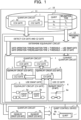
- FIG. 1 is a diagram illustrating an example of the quantum circuit design method according to the first embodiment.
- a quantum computer including a quantum circuit design device 10 and a qubit control device 8 is illustrated.
- the quantum circuit design device 10 can execute the quantum circuit design method according to the first embodiment, by executing a quantum circuit design program.
- the quantum circuit design device 10 is coupled to the qubit control device 8.
- the qubit control device 8 includes a plurality of qubits 8a, 8b,... and performs quantum calculation using the qubits 8a, 8b,....
- the quantum circuit design device 10 can design an appropriate quantum circuit 7 according to characteristics of the qubits 8a, 8b,... included in the qubit control device 8.
- the quantum circuit design device 10 includes a storage unit 11 and a processing unit 12.
- the storage unit 11 is, for example, a memory or a storage device included in the quantum circuit design device 10.
- the processing unit 12 is, for example, a processor or an arithmetic circuit included in the quantum circuit design device 10.
- the storage unit 11 stores a quantum circuit 1 and qubit characteristic information 2.
- the quantum circuit 1 is information indicating an operation procedure of the qubit used to obtain a solution of a problem to be solved by the quantum calculation.
- a gate operation on the qubit is indicated by the quantum gate.
- the quantum gate used for the quantum circuit 1 is not limited to a quantum gate supported by hardware of the quantum device of the quantum computer. Therefore, the quantum circuit 1 includes a quantum gate that operates three or more qubits.
- the quantum circuit 1 includes a CCX gate 1a (referred to as Toffoli gate) or a CCZ gate 1b.
- the processing unit 12 converts the quantum circuit 1 stored in the storage unit 11 into the quantum circuit 7 that can be mounted on the qubit control device 8. For example, the processing unit 12 converts the quantum gate that operates the three or more qubits in the quantum circuit 1 into an equivalent circuit obtained by combining a one-qubit gate or a two-qubit gate. Furthermore, in a case where the quantum device of the qubit control device 8 cannot perform a gate operation of a CX gate (CNOT gate) although the quantum device of the qubit control device 8 can perform a gate operation of a CZ gate, the processing unit 12 converts the CX gate into an equivalent circuit using the CZ gate. Specifically, the processing unit 12 executes the following processing.
- the processing unit 12 detects a first quantum gate that cannot execute the gate operation with the quantum device of the quantum computer, from the quantum circuit 1 indicating the gate operation to the plurality of qubits 8a, 8b,... included in the qubit control device 8 in the quantum computer.
- the first quantum gate is, for example, the CCX gate 1a or the CCZ gate 1b.
- the processing unit 12 determines an equivalent circuit to be mounted, from among a plurality of equivalent circuits that implements a gate operation same as that of the first quantum gate, based on a relaxation time of a qubit to be operated by the first quantum gate.
- the plurality of equivalent circuits includes quantum circuits using a second quantum gate that can execute the gate operation with the quantum device of the quantum computer.
- the processing unit 12 determines the equivalent circuit to be mounted, based on a ratio between a gate operation time of the two-qubit gate of the quantum computer and the relaxation time of the quantum bit to be operated. In this case, the processing unit 12 acquires a minimum value of the relaxation time of each of the plurality of qubits to be operated.
- the processing unit 12 compares a value of the ratio between the gate operation time and the minimum value of the relaxation time (gate operation time/relaxation time) with a predetermined threshold. If the "gate operation time/relaxation time" is less than the threshold, the processing unit 12 determines to perform conversion into an equivalent circuit using an iSWAP gate. Furthermore, if the "gate operation time/relaxation time" is equal to or more than the threshold, the processing unit 12 determines to perform conversion into the equivalent circuit using the CZ gate.
- the processing unit 12 converts the first quantum gate in the quantum circuit 1 into the determined equivalent circuit. For example, in a case where the detected first quantum gate is the CCX gate 1a, first, the processing unit 12 converts the CCX gate 1a into an equivalent circuit 3 that performs a gate operation similar to the CCX gate 1a.
- the equivalent circuit 3 includes a CCZ gate 3a.
- the processing unit 12 converts the CCZ gate 3a included in the equivalent circuit 3 into an equivalent circuit 4 that performs a gate operation similar to the CCZ gate 3a.
- the equivalent circuit 4 includes a CX gate 4a. Furthermore, in a case where the detected first quantum gate is the CCZ gate 1b, the processing unit 12 converts the CCZ gate 1b into the equivalent circuit 4.
- the processing unit 12 converts the CX gate 4a in the equivalent circuit 4 into one of two equivalent circuits 5 and 6 that perform a gate operation similar to the CX gate 4a.
- the equivalent circuit 5 includes iSWAP gates 5a and 5b.
- the equivalent circuit 6 includes a CZ gate 6a.
- the processing unit 12 converts the CX gate 4a in the equivalent circuit 4 into the equivalent circuit 5.
- the processing unit 12 converts the CX gate 4a in the equivalent circuit 4 into the equivalent circuit 6.
- the processing unit 12 instructs the qubit control device 8 to perform quantum calculation according to the quantum circuit 7 generated by converting the first quantum gate of the quantum circuit 1 into the equivalent circuit.
- the quantum circuit 7 includes equivalent circuits 7a and 7b, for example, instead of the CCX gate 1a and the CCZ gate 1b of the quantum circuit 1.
- the quantum circuit 7 includes only a quantum gate natively supported with the quantum device by the qubit control device 8.
- the qubit control device 8 performs a gate operation by the quantum gate indicated by the quantum circuit 7 on the qubits 8a, 8b,... and measures states of the qubits 8a, 8b,... after the gate operation according to the quantum circuit 7 has been performed.
- the processing unit 12 can convert the CCX gate 1a or the CCZ gate 1b into the equivalent circuits 7a and 7b with a less error rate, based on the relaxation time of the qubits 8a, 8b,.... As a result, an error rate of the quantum calculation by the qubit control device 8 is reduced, and highly accurate calculation becomes possible.
- the processing unit 12 determines the equivalent circuit to be mounted, based on the ratio between the gate operation time of the two-qubit gate and the relaxation time of the qubit to be operated. As a result, an influence of noise according to the relaxation time can be correctly evaluated, and it is possible to appropriately determine a conversion destination equivalent circuit.
- the processing unit 12 calculates the value of the ratio between the gate operation time and the relaxation time, using a minimum value of the relaxation time of each of the plurality of quantum gates operated by the first quantum gate to be converted, and compares the value with the threshold. In this way, the conversion destination equivalent circuit is determined, using the minimum value of the relaxation time of each quantum gate. As a result, the conversion destination equivalent circuit is determined, according to characteristics of a quantum gate with poor quality. Since an error of the gate operation on the qubit is accumulated for each gate operation, if there is a quantum gate with a high error rate, an error rate of a quantum circuit that operates the quantum gate also increases. Therefore, by determining the conversion destination equivalent circuit in accordance with the characteristics of the quantum gate with the poor quality, it is possible to correctly evaluate the quality of each of the plurality of equivalent circuits and to determine the conversion destination equivalent circuit.
- the processing unit 12 may periodically (for example, every day) measure the relaxation time of each of the qubits 8a, 8b,... and update the qubit characteristic information 2.
- the conversion destination equivalent circuit can be determined using the latest relaxation time of each of the qubits 8a, 8b,....
- the processing unit 12 determines the qubit operated by the quantum circuit, based on the fidelities of the plurality of qubits 8a, 8b,... included in the quantum computer. For example, the processing unit 12 determines a qubit group of which an average fidelity is the highest, from among continuous qubit groups as many as the number of qubits used for the quantum circuit 7, as a qubit group operated by the quantum circuit 7.
- the continuous qubit group includes a plurality of qubits in which qubits adjacent each other have a coupling relationship each other when these qubits are arranged in line.
- the second embodiment is a system that allocates a qubit optimum for a quantum circuit and performs quantum calculation with the quantum circuit optimized according to a relaxation time of a qubit, in consideration of a fidelity of the qubit.
- FIG. 2 is a diagram illustrating an example of a system configuration of the second embodiment.
- a quantum computer 300 is a gate-type quantum computer.
- the quantum computer 300 includes a control computer 100 and a qubit control device 200.
- terminal devices 401, 402,... are coupled via a network 20.
- the terminal devices 401, 402,... are computers used by users who request quantum calculation by the quantum computer 300.
- the control computer 100 receives quantum circuits from the terminal devices 401, 402,....
- the quantum circuit indicates order of operations on qubits by arrangement of elements such as gates.
- the qubit is a bit capable of expressing a superposed state of a state of "0" and a state of " 1".
- the control computer 100 instructs the qubit control device 200 to control the qubits according to the quantum circuits received from the terminal devices 401, 402,.... Furthermore, the control computer 100 acquires a measurement result of each qubit from the qubit control device 200.
- the qubit control device 200 includes a plurality of qubits and a device for operating each of the plurality of qubits.
- the plurality of qubits included in the qubit control device 200 may be, for example, in a superconducting system or an ion trap system. Furthermore, the plurality of qubits may be in a diamond spin system. In a case where the qubit is in the superconducting system, the qubit control device 200 may include a refrigerator for cooling the qubits.
- the qubit control device 200 irradiates the qubits with microwaves, in response to the instruction from the control computer 100, for example. Furthermore, the device for operating each of the plurality of qubits measures the state of each of the plurality of qubits and transmits the state to the control computer 100.
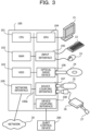
- FIG. 3 is a diagram illustrating a configuration example of hardware of the control computer.
- the entire device of the control computer 100 is controlled by a central processing unit (CPU) 101.
- the CPU 101 is a processor that executes a program command.
- the CPU 101 may include a plurality of processor cores.
- the CPU 101 may be a plurality of processors, or may be a micro processing unit (MPU), a digital signal processor (DSP), or the like.
- MPU micro processing unit
- DSP digital signal processor
- at least a part of functions implemented by the CPU 101 executing a program may be implemented by an electronic circuit such as an application specific integrated circuit (ASIC) or a programmable logic device (PLD).
- ASIC application specific integrated circuit
- PLD programmable logic device
- RAM random access memory
- peripheral devices are coupled via a bus 100a.
- the RAM 102 is a main storage device of the control computer 100.
- the RAM 102 at least a part of an operating system (OS) program or an application program to be executed by the CPU 101 is temporarily stored.
- OS operating system
- the RAM 102 various types of data to be used in processing by the CPU 101 is stored.
- the control computer 100 may include a memory of a type other than the RAM, or may include a plurality of memories.
- peripheral devices coupled to the bus 100a include a hard disk drive (HDD) 103, a graphics processing unit (GPU) 104, an input interface 105, an optical drive device 106, device coupling interfaces 107 and 108, and a network interface 109.
- HDD hard disk drive
- GPU graphics processing unit
- the HDD 103 is an auxiliary storage device of the control computer 100.
- the HDD 103 magnetically writes data to and reads data from a built-in magnetic disk.
- an OS program, an application program, and various types of data are stored.
- the control computer 100 may include other types of auxiliary storage devices such as a flash memory or a solid state drive (SSD), or may include a plurality of auxiliary storage devices.
- a keyboard 22 and a mouse 23 are coupled to the input interface 105.
- the input interface 105 transmits signals transmitted from the keyboard 22 and the mouse 23 to the CPU 101.
- the mouse 23 is an example of a pointing device, and another pointing device may also be used. Examples of the another pointing device include a touch panel, a tablet, a touch pad, a track ball, and the like.
- the optical drive device 106 reads data recorded in an optical disk 24 by using a laser beam or the like.
- the optical disk 24 is a portable recording medium in which data is recorded in a manner readable by reflection of light. Examples of the optical disk 24 include a digital versatile disc (DVD), a DVD-RAM, a compact disc read only memory (CD-ROM), a CD-recordable (R)/rewritable (RW), and the like.
- the device coupling interface 107 is a communication interface for coupling the peripheral devices to the control computer 100.
- a memory device 25 and a memory reader/writer 26 may be coupled to the device coupling interface 107.
- the memory device 25 is a recording medium equipped with a communication function with the device coupling interface 107.
- the memory reader/writer 26 is a device that writes data to a memory card 27 or reads data from the memory card 27.
- the memory card 27 is a card-type recording medium.
- the device coupling interface 108 is a communication interface for coupling the qubit control device 200 to the control computer 100.
- the control computer 100 transmits an instruction for controlling qubits to the qubit control device 200 via the device coupling interface 108.
- the network interface 109 is coupled to the network 20.
- the network interface 109 exchanges data with another computer or communication device via the network 20.
- the control computer 100 may implement processing functions of the second embodiment with the hardware configuration as described above.
- the quantum circuit design device 10 indicated in the first embodiment may also be implemented by hardware similar to that of the control computer 100 illustrated in FIG. 3 .
- the CPU 101 is an example of the processing unit 12 indicated in the first embodiment.
- the control computer 100 implements the processing functions of the second embodiment by executing, for example, a program recorded in a computer-readable recording medium.
- a program in which processing content to be executed by the control computer 100 is described may be recorded in various recording media.
- the program to be executed by the control computer 100 may be stored in the HDD 103.
- the CPU 101 loads at least a part of the programs in the HDD 103 into the RAM 102, and executes the loaded program.
- the program to be executed by the control computer 100 may also be recorded in a portable recording medium such as the optical disk 24, the memory device 25, or the memory card 27.
- the program stored in the portable recording medium may be executed after being installed to the HDD 103 under the control of the CPU 101.
- the CPU 101 may directly read and execute the program from the portable recording medium.
- the control computer 100 acquires a quantum circuit in which a procedure of a gate operation of the qubit for the quantum calculation is described, from the terminal devices 401, 402,....
- the quantum circuit acquired from the terminal devices 401, 402,... includes a gate operation of three or more qubit gates.
- a gate operation in the qubit control device 200 is limited to a gate operation of a one-qubit gate or a two-qubit gate. Therefore, the control computer 100 converts the quantum gate including three or more qubit gates included in the acquired quantum circuit into an equivalent circuit using the one-qubit gate or the two-qubit gate.
- the quantum circuit used in the following description has a horizontal line corresponding to each qubit that performs a gate operation. On the horizontal line, a quantum gate indicating a gate operation to be performed on the corresponding qubit is arranged. In the quantum circuit, a quantum gate indicating an operation to be performed earlier is arranged on the left.
- FIG. 4 is a diagram illustrating an example of the equivalent circuit of the CCX gate.
- a CCX gate 30 indicates that, in a case where two control bits (q 0 , q 1 ) are " 1", an X gate is acted (invert bit) on one target bit (q 2 ).
- a symbol obtained by combining + and a circle is arranged on a line corresponding to a qubit to be the target bit of the CCX gate 30, and points coupled to the symbol with a line are arranged on lines corresponding to the respective qubits to be the two control bits.
- Such a CCX gate 30 can be converted into an equivalent circuit 31 obtained by combining an H gate (Hadamard gate) and a CCZ gate 31a.
- the equivalent circuit 31 is a quantum circuit that performs a gate operation equivalent to the CCX gate 30.
- two H gates (rectangles described as "H” in FIG. 4 ) are arranged having the CCZ gate 31a interposed therebetween, in the qubit that is the target bit.
- the CCZ gate 31a indicates that, in a case where the two control bits (q 0 , q 1 ) are "1", a Z gate is acted (invert phase) on the one target bit (q 2 ).
- the CCZ gate 31a included in the equivalent circuit 31 can be converted into an equivalent circuit in which a one-qubit gate and a two-qubit gate are combined.
- FIG. 5 is a diagram illustrating an example of an equivalent circuit of the CCZ gate.
- An equivalent circuit 33 is a quantum circuit obtained by combining the one-qubit gate and the two-qubit gate, equivalent to a CCZ gate 32 for the qubits q 0 , q 1 , and q 2 .
- each of blocks described as T arranged on the horizontal lines corresponding to the respective qubits q 0 , q 1 , and q 2 indicates a T gate.
- the T gate indicates an operation for shifting a phase by a predetermined value.
- each of blocks described as T ⁇ arranged on the horizontal lines corresponding to the respective qubits q 0 , q 1 , and q 2 indicates a T ⁇ gate.
- the T ⁇ gate indicates an operation for shifting the phase by the predetermined value in an opposite direction to the T gate.
- each of symbols obtained by combining + and a circle arranged on the horizontal lines corresponding to the respective qubits q 0 , q 1 , and q 2 , and a point coupled to the symbol with a line and arranged on the line corresponding to each of the qubits q 0 , q 1 , and q 2 indicate CX gates.
- the symbol obtained by combining + and the circle is arranged on a line corresponding to a qubit to be a target bit of the CX gate, and the point is arranged on a line corresponding to a qubit to be a control bit of the CX gate.
- the CX gate indicates that a bit of the target bit is inverted in a case where the control bit is "1".
- the CCZ gate 32 can be converted into the equivalent circuit 33 obtained by combining the one-qubit gate and the two-qubit gate.
- the equivalent circuit 33 includes CX gates 33a and 33b for the qubits q 0 and q 2 .
- the two-qubit gate can be operated only between the coupled two qubits.
- an actual qubit in the quantum computer 300 is allocated to the qubit indicated by the quantum circuit, coupled qubits among the actual qubits are allocated to adjacent qubits in the quantum circuit.
- uncoupled qubits, among the actual qubits are allocated to qubits that are not adjacent in the quantum circuit.
- the equivalent circuit 33 is converted into an equivalent circuit 34 using a SWAP gate 34a.
- the SWAP gate 34a is inserted, at a position in front of the CX gates 33a and 33b in the equivalent circuit 33.
- the SWAP gate 34a indicates a gate operation for exchanging states of two qubits.
- the CX gates 33a and 33b are replaced with CX gates 34b and 34c for the qubits q 0 and q 1 .
- a final T gate 33c of the qubit q 2 in the equivalent circuit 33 is replaced with a final T gate 34d of the qubit q 1 in the equivalent circuit 34.
- qubits to be the quantum calculation targets on the quantum algorithm be x 0 , x 1 , and x 2 .
- the equivalent circuit 33 it is assumed that the actual qubit q 0 in the qubit control device 200 be allocated to the qubit x 0 .
- the actual qubit q 1 in the qubit control device 200 be allocated to the qubit x 1 .
- the actual qubit q 2 in the qubit control device 200 be allocated to the qubit x 2 .
- a quantum state of the qubit x 0 is obtained by measuring the qubit q 0
- a quantum state of the qubit x 1 is obtained by measuring the qubit q 1
- a quantum state of the qubit x 2 is obtained by measuring the qubit q 2 .
- the equivalent circuit 34 is executed. Since the SWAP gate 34a is included in the equivalent circuit 34, an actual qubit to be allocated is changed, for the qubits x 1 and x 2 of which states are exchanged in the SWAP gate 34a.
- the qubit q 1 is allocated to the qubit x 1 on the quantum algorithm at the start of the execution of the equivalent circuit 34
- the qubit q 2 is allocated at the end of the execution of the equivalent circuit 34.
- the qubit q 1 is allocated at the end of the execution of the equivalent circuit 34.
- the quantum state of the qubit x 0 is obtained by measuring the qubit q 0
- the quantum state of the qubit x 2 is obtained by measuring the qubit q 1
- the quantum state of the qubit x 1 is obtained by measuring the qubit q 2 .
- the SWAP gate 34a in the equivalent circuit 34 is converted into a combination of CX gates. Furthermore, the equivalent circuit 34 is optimized.
- FIG. 6 is a diagram illustrating an example of the optimized equivalent circuit of the CCZ gate.
- conversion of a circuit indicated by three conversion patterns is performed on the equivalent circuit 34, and an equivalent circuit 35 is formed.
- the first conversion pattern indicates conversion from the SWAP gate into three CX gates.
- the second conversion pattern indicates that the consecutive two CX gates having the common control bit and target bit are the same as those in a case where no gate operation is performed and these CX gates can be deleted.
- the third conversion pattern indicates that, when there is the T gate in front of or behind the control bit of the CX gate, the position of the control bit of the CX gate and the position of the T gate may be interchanged.
- the SWAP gate 34a of the equivalent circuit 34 is converted into three CX gates according to the "conversion pattern 1", using a qubit q1 0 in the "conversion pattern 1" as the qubit q 2 of the equivalent circuit 34 and a qubit q1 1 as the qubit q 1 of the equivalent circuit 34.
- the qubit q 2 serves as the control bit
- the qubit q 1 serves as the target bit.
- the first one of the three CX gates converted from the SWAP gate 34a and a CX gate 34f immediately before the SWAP gate 34a have a common control bit and a common target bit.
- the "conversion pattern 2" can be applied.
- the first one of the three CX gates converted from the SWAP gate 34a and the CX gate 34f immediately before the SWAP gate 34a are deleted.
- What remains in the equivalent circuit 35 after conversion are two CX gates 35a including the second and third CX gates among the three CX gates converted from the SWAP gate 34a.
- a control bit of a CX gate 34e is arranged before the final T gate 34d.
- the T gate 34d can be moved to the front of the CX gate 34e, by applying the "conversion pattern 3".
- a T gate 35b corresponding to the T gate 34d is arranged in front of a final CX gate 35c for the qubit q 1 .
- a gate operation time of the two qubits is 10 times or more than a gate operation time of the one-qubit gate. Therefore, as an index of the gate operation time for the equivalent circuit 35 after conversion, the number of two-qubit gates can be used.
- the two-qubit gate included in the equivalent circuit 35 includes seven CX gates.
- the equivalent circuit of the CCX gate is obtained.
- the quantum computer 300 supports the CZ gate
- the quantum computer 300 does not support the CX gate.
- a gate such as the CZ gate or the iSWAP gate is supported as the native gate.
- the CX gate is not necessarily supported.
- by replacing the CX gate included in the equivalent circuit 35 with the equivalent circuit using the CZ gate a quantum circuit that can perform the gate operation with the qubit control device 200 is obtained.
- FIG. 7 is a diagram illustrating an example of a mountable equivalent circuit of the CCZ gate.
- the CX gate can be converted into an equivalent circuit 41 using the CZ gate, as indicated in a "conversion pattern 4".
- the CX gate is replaced with the CZ gate, and two H gates are arranged with the CZ gate interposed therebetween, in the qubit serving as the target bit of the CX gate.
- an equivalent circuit 36 is obtained.
- the iSWAP gate is used other than the CZ gate. Then, the CX gate can be replaced with the equivalent circuit using the iSWAP gate.
- FIG. 8 is a diagram illustrating an example of the equivalent circuit of the CX gate using the iSWAP gate.
- An equivalent circuit 42 of the CX gate includes two iSWAP gates 42a and 42b and five rotation gates 42c to 42g.
- the rotation gate 42c that rotates by "- ⁇ /2" around the Z axis is arranged on a side of the control bit of the CX gate.
- the rotation gate 42d that rotates by " ⁇ /2" around the X axis and the rotation gate 42e that rotates by " ⁇ /2” around the Z axis are arranged.
- the first iSWAP gate 42a is arranged.
- the rotation gate 42f that rotates by " ⁇ /2" around the X axis is arranged on the side of the control bit of the CX gate.
- the second iSWAP gate 42b is arranged.
- the rotation gate 42g that rotates by " ⁇ /2" around the Z axis is arranged on the side of the target bit of the CX gate.
- the quantum computer 300 is an NISQ.
- the NISQ has a small number of qubits and is not able to correct errors.
- the error occurs due to an influence of noise, and as the number of gates included in the quantum circuit is larger, the occurred errors accumulate. Therefore, when the quantum gate included in the quantum circuit is converted into the native gate, implementation in consideration of noise is required. For example, in a case where the CCX gate is mounted, it is required to appropriately determine whether or not to mount the CCX gate on the equivalent circuit using the CX gate or mount the CCX gate using the iSWAP gate.
- Ease of receiving an influence of noise regarding a qubit is represented by a fidelity.
- a higher fidelity indicates that the qubit is less likely to receive the influence of the noise.
- the fidelity of the quantum gate is an index indicating whether or not the quantum gate operation on the qubit is close to an ideal operation.
- the qubit has a limited time when the qubit can hold information without losing the information. Such a time is referred to as a relaxation time. When an operation time of the quantum circuit exceeds the relaxation time, the qubit information is lost, and an error occurs.
- the relaxation time includes an average time (energy relaxation time) in which an excited state is maintained and an average time (phase relaxation time) in which superposition is maintained.
- T1 average time
- phase relaxation time is referred to as "T2”.
- the index indicating the likelihood of the occurrence of the error includes the fidelity of the qubit, the relaxation time of the qubit, the fidelity of the quantum gate, or the like.
- a value of each index of the likelihood of the occurrence of the error differs for each qubit, due to variations at the time of producing the quantum device or the like. Therefore, it is important to appropriately determine on which qubit the quantum circuit is mounted with which native gate, when the control computer 100 converts the acquired quantum circuit into the mountable quantum circuit.
- control computer 100 determines the quantum circuit to be mounted, based on the index of the likelihood of the occurrence of the error.
- the control computer 100 measures the fidelity and T1 of all the qubits.
- the control computer 100 allocates a qubit with a high fidelity in which qubits as many as qubits used to execute the quantum algorithm can be continuously arranged, to the quantum circuit to be executed.
- the control computer 100 determines a native two quantum gates used for the quantum circuit to be mounted, based on a threshold based on the allocated qubit having the shortest T1 value among the three qubits for operating the CCX gate or the CCZ gate.
- the storage unit 110 stores conversion information 111, connection topology information 112, and qubit characteristic information 113.
- conversion information 111 a quantum gate to be converted and an equivalent circuit are registered in association with each other.
- connection topology information 112 connection topology information indicating a coupling relationship between the qubits in the qubit control device 200 is registered.
- qubit characteristic information 113 the fidelity and T1 of each qubit in the qubit control device 200 are registered.
- the qubit characteristics measurement unit 130 measures the fidelity and T1 of each qubit in the qubit control device 200, at predetermined intervals. For example, the qubit characteristics measurement unit 130 controls the qubit control device 200 and measures the fidelity and T1, about once a day. The qubit characteristics measurement unit 130 updates the qubit characteristic information 113, each time when the qubit characteristics measurement unit 130 performs measurement.
- the qubit allocation unit 140 allocates the qubit in the qubit control device 200 to a qubit used for the quantum circuit acquired by the quantum calculation control unit 120.
- the qubit allocation unit 140 refers to the connection topology information 112 and allocates the qubits, in accordance with a condition such that vertically adjacent qubits are coupled in the quantum circuit.
- the qubit allocation unit 140 adopts an allocation pattern with a high average fidelity of the included qubit.
- the gate conversion unit 150 refers to the conversion information 111 and converts the quantum circuit acquired from the terminal devices 401, 402,... into the quantum circuit that can be mounted on the qubit control device 200. Note that, when converting the CX gate, the gate conversion unit 150 determines the conversion destination equivalent circuit, based on the minimum value of the values of T1 of the respective qubits allocated to the quantum circuit.
- lines coupling the individual elements illustrated in FIG. 9 indicate a part of a communication path, and a communication path other than the illustrated communication path may also be set. Furthermore, the function of each element illustrated in FIG. 9 may be implemented, for example, by causing a computer to execute a program module corresponding to the element.
- FIG. 10 is a diagram illustrating an example of the conversion information.
- the conversion information 111 fields of a detection gate and an equivalent circuit are provided.
- a gate detected as a conversion target is set.
- an equivalent circuit of the detection gate is set.
- the equivalent circuit 31 using the CCZ gate is registered, in association with the CCX gate.
- the equivalent circuit 35 obtained by combining the one-qubit gate and two-qubits is registered, in association with the CCZ gate.
- the equivalent circuit 41 using the CZ gate and the equivalent circuit 42 using the iSWAP gate are registered, in association with the CX gate.
- FIG. 11 is a diagram illustrating an example of the connection topology information.
- the connection topology information 112 a plurality of coupling qubit pairs indicating two qubits having a coupling relationship is registered.
- an operation of the two-qubit gate using these as an operation target can be executed by the qubit control device 200.
- FIG. 12 is a diagram illustrating an example of the qubit characteristic information.
- a fidelity and T1 of the corresponding qubit are set, in association with an identifier of each qubit included in the qubit control device 200.
- the fidelity and T1 of the qubit are periodically updated by the qubit characteristics measurement unit 130.
- FIG. 13 is a flowchart illustrating an example of a procedure of qubit characteristic information update processing. Hereinafter, the processing illustrated in FIG. 13 will be described in order of step numbers.
- Step S101 The qubit characteristics measurement unit 130 determines whether or not a preset measurement time (for example, daily specific time) has come. In a case where the measurement time comes, the qubit characteristics measurement unit 130 proceeds the processing to step S102. Furthermore, if the measurement time does not come, the qubit characteristics measurement unit 130 repeats step S101 and waits for the measurement time.
- a preset measurement time for example, daily specific time
- the qubit characteristics measurement unit 130 controls the qubit control device 200 and measures the fidelity and T1 of each qubit.
- Step S103 The qubit characteristics measurement unit 130 updates the values of the fidelity and the T1 of each qubit in the qubit characteristic information 113 to latest measurement values. Thereafter, the qubit characteristics measurement unit 130 proceeds the processing to step S101.
- the reference t represents a gate execution time.
- the reference p represents a probability vector (probability vector).
- p 0. From the formula (1), it is found that the influence of the noise depends on a ratio between the gate execution time t and the relaxation time (T1 or T2). Specifically, as a value of the ratio between the gate execution time t and the relaxation time (gate execution time/relaxation time) is larger, the influence of the noise is more easily received. That is, it is not possible to correctly determine the degree of the influence of the noise by using only the relaxation time.
- the gate execution time t of the one-qubit gate is a time determined in advance in the quantum computer 300 and does not depend on a type of the one-qubit gate. Similarly, the gate execution time of the two-qubit gate also does not depend on a type of the two-qubit gate.
- the operation of the two-qubit gate takes time, and the gate execution time of the two-qubit gate is set to be a value much longer than the gate execution time of the one-qubit gate. Therefore, in the quantum circuit, the number of two-qubit gates is used as the index of the likelihood of the occurrence of the error.
- the number of two-qubit gates of the quantum circuit is referred to as a circuit length. In a quantum circuit with a shorter circuit length, an error is less likely to occur.
- the iSWAP gate has a smaller influence of coherent noise than the CZ gate.
- the equivalent circuit 41 using the CZ gate includes only one two-qubit gate.
- the equivalent circuit 42 using the iSWAP gate includes two two-qubit gates. That is, the circuit length of the equivalent circuit 42 is twice of the equivalent circuit 41. As the circuit length is longer, an influence of decoherence noise increases. Although the decoherence noise varies depending on the ratio between the relaxation time and the gate operation time, the relaxation time differs for each qubit.
- the influence of the coherent noise becomes larger than the noise regarding the relaxation time.
- the influence of the coherent noise is larger, even if the circuit length is doubled, there is a possibility that the iSWAP gate that has a smaller influence of the coherent noise has a smaller influence of the noise as a whole. Therefore, in a case where the gate conversion unit 150 converts the CX gate into one of the equivalent circuits 41 or 42, the gate conversion unit 150 determines the conversion destination equivalent circuit, based on the value of the ratio between the gate execution time and the relaxation time, for the two-qubit gate.
- FIG. 14 is a diagram illustrating an example of CCX gate conversion processing.
- the gate conversion unit 150 converts the CCX gate 30 into the equivalent circuit 31 using the CCZ gate 31a.
- the gate conversion unit 150 converts the CCZ gate 31a in the equivalent circuit 31 into the equivalent circuit 35 including one qubit and two qubits.
- the equivalent circuit 35 includes the seven CX gates. Therefore, the gate conversion unit 150 converts each of the seven CX gates into one of the equivalent circuits 41 and 42, according to whether or not the value of the ratio between the gate execution time t and T1 of the two-qubit gate (t/T1) is less than a threshold.
- the gate conversion unit 150 converts each CX gate into the equivalent circuit 41 using the CZ gate. In this case, the quantum circuit after conversion includes seven CZ gates. Furthermore, if t/T1 is less than the threshold, the gate conversion unit 150 converts each CX gate into the equivalent circuit 42 using the iSWAP gate. In this case, the quantum circuit after conversion includes 14 iSWAP gates.
- FIG. 15 is a flowchart illustrating an example of a procedure of quantum circuit conversion processing. Hereinafter, the processing illustrated in FIG. 15 will be described in order of step numbers.
- the quantum calculation control unit 120 acquires the quantum circuit. For example, the quantum calculation control unit 120 receives, from the terminal devices 401, 402,..., requests for quantum calculation by the quantum computer 300 and the quantum circuits.
- the qubit allocation unit 140 generates a candidate qubit group that can be continuously arranged, based on the connection topology information 112. Capable of being continuously arranged means that a condition is satisfied such that the coupled qubits of the qubit control device 200 can be allocated to the vertically adjacent qubits in the quantum circuit.
- the qubit allocation unit 140 refers to the qubit characteristic information 113 and calculates an average value of the fidelity of the qubit belonging to each generated candidate qubit group.
- the qubit allocation unit 140 determines a candidate qubit group with the highest average fidelity as an allocation determination of the qubit of the quantum circuit.
- the gate conversion unit 150 detects three qubits to be subjected to the CCX gate or CCZ gate operation, from the acquired quantum circuit.
- Step S206 The gate conversion unit 150 determines whether or not the three qubits are detected. In a case where it is determined that the three qubits are detected, the gate conversion unit 150 proceeds the processing to step S207. Furthermore, in a case of determining that the three qubits are not detected, the gate conversion unit 150 proceeds the processing to step S211.
- the gate conversion unit 150 acquires a minimum value among the values of T1 of the respective detected three qubits, from the qubit characteristic information 113.
- Step S208 The gate conversion unit 150 determines whether or not the value of the ratio between the gate execution time t and the acquired T1 (t/T1) is less than the threshold. If the value of the ratio is less than the threshold, the gate conversion unit 150 proceeds the processing to step S209. Furthermore, if the value of the ratio is equal to or more than the threshold, the gate conversion unit 150 proceeds the processing to step S210.
- Step S209 The gate conversion unit 150 converts all the CCX gates or CCZ gates executed by the detected three qubits into the equivalent circuit using the iSWAP gate. Thereafter, the gate conversion unit 150 proceeds the processing to step S205.
- Step S210 The gate conversion unit 150 converts all the CCX gates or CCZ gates executed by the detected three qubits into the equivalent circuit using the CZ gate. Thereafter, the gate conversion unit 150 proceeds the processing to step S205.
- the quantum calculation control unit 120 controls the qubit control device 200 in accordance with the quantum circuit after the conversion.
- the CCX gate or the CCZ gate can be converted into the equivalent circuit with less influence of the noise.
- the threshold used to determine the equivalent circuit can be determined by evaluating the influence of the noise of the equivalent circuit using the iSWAP gate and the equivalent circuit using the CZ gate, for example.
- An evaluation index of the influence from the noise includes, for example, total variation distance (TVD).
- the TVD is based on a sum of an ideal probability with no noise and a probability with noise.
- the reference p ideal (x) indicates an appearance probability of a sequence (bit sequence x) of values of qubits in an ideal situation (situation with no noise).
- the reference p (x) is an appearance probability of a bit sequence x measured by actual measurement or simulation.
- a difference between a probability when noise occurs and a probability when no noise occurs is calculated. Then, 1/2 of the sum of these differences is the TVD. A smaller value of the TVD indicates less influence of the noise.
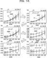
- FIG. 16 is a diagram illustrating an example of a change in the TVD for each equivalent circuit according to the noise.
- the value of the TVD according to the noise differs for each oracle to be calculated.
- graphs 51 to 56 the TVD according to the noise is obtained for all the oracles, and a change in an average value of the TVD according to an increase in the noise is indicated for each of the plurality of equivalent circuits of the CCX gate.
- the horizontal axis of the graphs 51 to 56 indicates a magnitude of the noise, and the vertical axis indicates the TVD.
- the noise is, for example, over-rotation noise (over-rotation noise).
- the graphs 51 to 56 have values of t/T1 different from each other.
- a change in an average value of the TVD of the equivalent circuit using the iSWAP gate is indicated by a thin polygonal line
- a change in an average value of the TVD of the equivalent circuit using the CZ gate is indicated by a thick polygonal line.
- the equivalent circuit using the iSWAP gate constantly has a smaller value of the TVD than the equivalent circuit using the CZ gate.
- the equivalent circuit using the CZ gate has a smaller value of the TVD than the equivalent circuit using the iSWAP gate.
- the noise becomes larger than "0.02”
- the equivalent circuit using the iSWAP gate has a smaller value of the TVD than the equivalent circuit using the CZ gate.
- the equivalent circuit using the CZ gate has a smaller value of the TVD than the equivalent circuit using the iSWAP gate.
- the noise becomes larger than "0.04", the equivalent circuit using the iSWAP gate has a smaller value of the TVD than the equivalent circuit using the CZ gate.
- the equivalent circuit using the CZ gate constantly has a smaller value of the TVD than the equivalent circuit using the iSWAP gate.
- the equivalent circuit using the CZ gate constantly has a smaller value of the TVD than the equivalent circuit using the iSWAP gate.
- the equivalent circuit using the CZ gate constantly has a smaller value of the TVD than the equivalent circuit using the iSWAP gate.
- the gate conversion unit 150 converts the CCX or CCZ gate into the equivalent circuit using the iSWAP gate. Furthermore, if “t/T1 ⁇ 10 -4 " the gate conversion unit 150 converts the CCX or CCZ gate into the equivalent circuit using the CZ gate.
- the quantum circuit to be calculated can be optimized to a quantum circuit with reduced influence of the noise and mounted on the qubit control device 200.
- an implementation method in a case where quantum calculation is performed with the three-qubit Grover's algorithm will be described with reference to FIGs. 17 to 19 .
- FIG. 17 is a diagram illustrating an example of a quantum circuit of the three-qubit Grover's algorithm.
- a quantum circuit 60 indicates order of operations on the respective qubits q 0 , q 1 , and q 2 in a case where the Grover's algorithm to be repeated once is executed with the three qubits.
- an operation of an H gate is performed as initialization processing. As a result, a superposed state of all states is generated.
- an operation of an oracle is performed on the qubits q 0 , q 1 , and q 2 .
- a three-qubit CCZ gate operation is performed. Thereafter, the operation of the X gate is performed on each of the qubits q 0 , q 1 , and q 2 again.
- an amplification operation is performed.
- the operation of the H gate and the operation of the X gate are performed on each of the qubits q 0 , q 1 , and q 2 .
- the three-qubit CCZ gate operation is performed.
- the operation of the X gate and the operation of the H gate are performed on each of the qubits q 0 , q 1 , and q 2 .
- each of the qubits q 0 , q 1 , and q 2 is measured.
- each of the qubits q 0 , q 1 , and q 2 is determined to be in the state of "0" or "1".
- the quantum computer 300 may include a device that performs a gate operation on two or less qubits, and does not have a device that may perform a gate operation on three or more qubits.
- a gate for three qubits such as the CCZ gate is converted into an equivalent circuit obtained by combining gates for two qubits or one qubit.
- the quantum circuit 60 includes two three-qubit CCZ gates, and these CCZ gates are first converted into the equivalent circuit 35 (refer to FIG. 10 ).
- FIG. 18 is a diagram illustrating an example of an equivalent circuit of a quantum circuit of the Grover's algorithm.
- a quantum circuit 61 including a one-qubit gate and a two-qubit gate is generated.
- the quantum circuit 61 includes 14 CX gates.
- the quantum circuit 61 includes 14 CX gates. All of the 14 CX gates are converted into the equivalent circuit using the iSWAP gate or the equivalent circuit using the CZ gate.
- the threshold of t/T1 used to determine into which equivalent circuit the CX gate is converted is determined based on the change in the TVD according to noise in the Grover's algorithm.
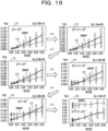
- FIG. 19 is a diagram illustrating an example of a change in the TVD for each equivalent circuit according to the noise in the Grover's algorithm.
- the TVD according to the noise is obtained for all the oracles, and a change in an average value of the TVD according to an increase in the noise is indicated for each of the plurality of equivalent circuits of the CCX gate.
- the horizontal axis of the graphs 71 to 76 indicates a magnitude of the noise, and the vertical axis indicates the TVD.
- a change in an average value of the TVD of the equivalent circuit using the iSWAP gate is indicated by a thin polygonal line
- a change in an average value of the TVD of the equivalent circuit using the CZ gate is indicated by a thick polygonal line.
- the equivalent circuit using the CZ gate has a smaller value of the TVD than the equivalent circuit using the iSWAP gate.
- the equivalent circuit using the iSWAP gate has a smaller value of the TVD than the equivalent circuit using the CZ gate.
- the equivalent circuit using the CZ gate Before the noise becomes "0.03", the equivalent circuit using the CZ gate has a smaller value of the TVD than the equivalent circuit using the iSWAP gate.
- the noise is equal to or more than "0.03”
- the equivalent circuit using the iSWAP gate has a smaller value of the TVD than the equivalent circuit using the CZ gate.
- the equivalent circuit using the CZ gate constantly has a smaller value of the TVD than the equivalent circuit using the iSWAP gate.
- the threshold of "t/T1" when the equivalent circuit is determined is set to "10 -4 ". That is, if “t/T1 ⁇ 10- 4 ", the gate conversion unit 150 converts the CCX or CCZ gate into the equivalent circuit using the iSWAP gate. Furthermore, if “t/T1 ⁇ 10 -4 " the gate conversion unit 150 converts the CCX or CCZ gate into the equivalent circuit using the CZ gate.
- the fidelity and T1 of each qubit are periodically measured.
- the qubit to be used can be determined and the quantum circuit can be mounted, based on the fidelity and T1 in the latest state when the quantum calculation is performed, and it is possible to stably perform the quantum calculation with high accuracy. That is, the fidelity or T1 of the qubit is not fixed and changes depending on an environment of the quantum computer 300 or the lapse of time. Therefore, by periodically measuring the fidelity or T1, accuracy of the fidelity or T1 at the time when the quantum calculation is performed is improved.
- the control computer 100 can convert the quantum gate into an appropriate equivalent circuit based on the relaxation time. Furthermore, the control computer 100 can convert the CX gate included in the quantum circuit acquired from the terminal devices 401, 402,... into the quantum circuit using the iSWAP gate or the equivalent circuit using the CZ gate, based on the relaxation time.
Landscapes
- Engineering & Computer Science (AREA)
- General Physics & Mathematics (AREA)
- Theoretical Computer Science (AREA)
- Physics & Mathematics (AREA)
- Software Systems (AREA)
- Mathematical Analysis (AREA)
- Evolutionary Computation (AREA)
- Data Mining & Analysis (AREA)
- Condensed Matter Physics & Semiconductors (AREA)
- Mathematical Optimization (AREA)
- Pure & Applied Mathematics (AREA)
- Computing Systems (AREA)
- General Engineering & Computer Science (AREA)
- Mathematical Physics (AREA)
- Computational Mathematics (AREA)
- Artificial Intelligence (AREA)
- Superconductor Devices And Manufacturing Methods Thereof (AREA)
- Logic Circuits (AREA)
Abstract
Description
- The present invention relates to a quantum circuit design program, a quantum circuit design method, and a quantum circuit design device.
- Currently, an available quantum computer is a type called a noisy intermediate-scale quantum computer (NISQ) using qubits of a superconducting system or an ion trap system. These quantum devices have an error rate of about 1% and the number of qubits of about 10 to 1000. It is not possible for such a small quantum computer to completely correct errors. Therefore, when quantum calculation is performed on the quantum computer, it is important to perform quantum calculation with a quantum circuit for reducing errors as possible.
- Furthermore, in the quantum computer, as a quantum gate for operating a qubit, a one-qubit gate and a two-qubit gate are mounted. These quantum gates are called native gates. Which quantum gate of the two-qubit gate is supported as the native gate depends on a system of a quantum device adopted in the quantum computer.
- On the other hand, a quantum circuit created in response to a problem to be solved may include a quantum gate other than the native gate. Therefore, the quantum gate other than the native gate is converted into an equivalent circuit obtained by combining the native gates, and then, is mounted on a qubit control device that performs a gate operation of the qubit. For example, a three-qubit gate such as a CCX (Toffoli) gate is implemented using the plurality of two-qubit gates. A CnX gate or a CnZ gate (n is integer equal to or more than three) having three or more control bits is converted into the plurality of CCX gates, and then, converted into the native gate.
- As a technique related to improvement in processing executed by the quantum computer, for example, a constant folding method in compilation of a quantum algorithm has been proposed. Furthermore, a method for designing a quantum computing circuit specific for an application or an algorithm for a specific application or algorithm has been proposed. Moreover, a technique has been proposed for reusing a single physical qubit by an active reset operation, if use times do not overlap, in a case where a quantum algorithm uses a logical qubit only for a short time.
- When a quantum gate that is not supported by a quantum device of a quantum computer is converted into an equivalent circuit including a native gate, a plurality of equivalent circuits that can serve as conversion destinations exists in some cases. In this case, it is desirable to perform conversion into an equivalent circuit with a smaller error rate of quantum calculation from among the plurality of equivalent circuits.
- The error rate of the equivalent circuit depends on characteristics of a qubit used for the equivalent circuit. However, typically, conversion into an equivalent circuit in consideration of the characteristics of the qubit is not performed. Therefore, a quantum gate to be converted is mechanically converted into an equivalent circuit that is associated with the quantum gate in advance, and there is a possibility that the error rate of the quantum calculation increases. When the error rate of the quantum calculation increases, this deteriorates calculation accuracy.
- In one aspect, an object of this case is to improve accuracy of quantum calculation.
- In one proposal, a quantum circuit design program that causes a computer to execute the following processing is provided.
- The computer detects a first quantum gate of which a gate operation cannot be performed by a quantum device, from a quantum circuit indicating a gate operation on a plurality of qubits included in the quantum device. The computer determines an equivalent circuit to be mounted, from among a plurality of equivalent circuits that can perform a gate operation same as the first quantum gate by a second quantum gate of which a gate operation can be performed by the quantum device, based on a relaxation time of a qubit to be operated by the detected first quantum gate. Then, the computer converts the first quantum gate in the quantum circuit into the determined equivalent circuit.
- According to one mode, it is possible to improve accuracy of quantum calculation.
- The object described above and other objects, features, and advantages of the present invention will become clear from the following description related to the appended drawings, which represent preferred embodiments as examples of the present invention.
-
-
FIG. 1 is a diagram illustrating an example of a quantum circuit design method according to a first embodiment. -
FIG. 2 is a diagram illustrating an example of a system configuration of a second embodiment. -
FIG. 3 is a diagram illustrating a configuration example of hardware of a control computer. -
FIG. 4 is a diagram illustrating an example of an equivalent circuit of a CCX gate. -
FIG. 5 is a diagram illustrating an example of an equivalent circuit of a CCZ gate. -
FIG. 6 is a diagram illustrating an example of an optimized equivalent circuit of a CCZ gate. -
FIG. 7 is a diagram illustrating an example of a mountable equivalent circuit of the CCZ gate. -
FIG. 8 is a diagram illustrating an example of an equivalent circuit of a CX gate using an iSWAP gate. -
FIG. 9 is a block diagram illustrating an example of functions of the control computer. -
FIG. 10 is a diagram illustrating an example of conversion information. -
FIG. 11 is a diagram illustrating an example of connection topology information. -
FIG. 12 is a diagram illustrating an example of qubit characteristic information. -
FIG. 13 is a flowchart illustrating an example of a procedure of qubit characteristic information update processing. -
FIG. 14 is a diagram illustrating an example of CCX gate conversion processing. -
FIG. 15 is a flowchart illustrating an example of a procedure of quantum circuit conversion processing. -
FIG. 16 is a diagram illustrating an example of a change in a TVD for each equivalent circuit according to noise. -
FIG. 17 is a diagram illustrating an example of a quantum circuit of a three-qubit Grover's algorithm. -
FIG. 18 is a diagram illustrating an example of an equivalent circuit of the quantum circuit of the Grover's algorithm. -
FIG. 19 is a diagram illustrating an example of a change in the TVD for each equivalent circuit according to noise in the Grover's algorithm. - Hereinafter, the present embodiments will be described with reference to the drawings. Note that each of the embodiments may be implemented in combination with the plurality of embodiments as long as no contradiction arises.
- A first embodiment is a quantum circuit design method for converting a quantum gate into an equivalent circuit that can reduce an error rate, in consideration of characteristics of a qubit to be used, when the quantum gate that is not supported by a quantum device of a quantum computer is converted into a native gate.
-
FIG. 1 is a diagram illustrating an example of the quantum circuit design method according to the first embodiment. InFIG. 1 , a quantum computer including a quantumcircuit design device 10 and aqubit control device 8 is illustrated. The quantumcircuit design device 10 can execute the quantum circuit design method according to the first embodiment, by executing a quantum circuit design program. - The quantum
circuit design device 10 is coupled to thequbit control device 8. Thequbit control device 8 includes a plurality ofqubits qubits circuit design device 10 can design an appropriatequantum circuit 7 according to characteristics of thequbits qubit control device 8. - The quantum
circuit design device 10 includes astorage unit 11 and aprocessing unit 12. Thestorage unit 11 is, for example, a memory or a storage device included in the quantumcircuit design device 10. Theprocessing unit 12 is, for example, a processor or an arithmetic circuit included in the quantumcircuit design device 10. - The
storage unit 11 stores aquantum circuit 1 and qubitcharacteristic information 2. Thequantum circuit 1 is information indicating an operation procedure of the qubit used to obtain a solution of a problem to be solved by the quantum calculation. In thequantum circuit 1, a gate operation on the qubit is indicated by the quantum gate. The quantum gate used for thequantum circuit 1 is not limited to a quantum gate supported by hardware of the quantum device of the quantum computer. Therefore, thequantum circuit 1 includes a quantum gate that operates three or more qubits. For example, thequantum circuit 1 includes aCCX gate 1a (referred to as Toffoli gate) or aCCZ gate 1b. - The qubit
characteristic information 2 stores information regarding the characteristics of each of thequbits qubit control device 8. For example, the qubitcharacteristic information 2 includes a relaxation time indicating a period in which information regarding a quantum state of each of thequbits characteristic information 2 can include a fidelity for each of thequbits - The
processing unit 12 converts thequantum circuit 1 stored in thestorage unit 11 into thequantum circuit 7 that can be mounted on thequbit control device 8. For example, theprocessing unit 12 converts the quantum gate that operates the three or more qubits in thequantum circuit 1 into an equivalent circuit obtained by combining a one-qubit gate or a two-qubit gate. Furthermore, in a case where the quantum device of thequbit control device 8 cannot perform a gate operation of a CX gate (CNOT gate) although the quantum device of thequbit control device 8 can perform a gate operation of a CZ gate, theprocessing unit 12 converts the CX gate into an equivalent circuit using the CZ gate. Specifically, theprocessing unit 12 executes the following processing. - The
processing unit 12 detects a first quantum gate that cannot execute the gate operation with the quantum device of the quantum computer, from thequantum circuit 1 indicating the gate operation to the plurality ofqubits qubit control device 8 in the quantum computer. The first quantum gate is, for example, theCCX gate 1a or theCCZ gate 1b. - Next, the
processing unit 12 determines an equivalent circuit to be mounted, from among a plurality of equivalent circuits that implements a gate operation same as that of the first quantum gate, based on a relaxation time of a qubit to be operated by the first quantum gate. The plurality of equivalent circuits includes quantum circuits using a second quantum gate that can execute the gate operation with the quantum device of the quantum computer. For example, theprocessing unit 12 determines the equivalent circuit to be mounted, based on a ratio between a gate operation time of the two-qubit gate of the quantum computer and the relaxation time of the quantum bit to be operated. In this case, theprocessing unit 12 acquires a minimum value of the relaxation time of each of the plurality of qubits to be operated. Then, theprocessing unit 12 compares a value of the ratio between the gate operation time and the minimum value of the relaxation time (gate operation time/relaxation time) with a predetermined threshold. If the "gate operation time/relaxation time" is less than the threshold, theprocessing unit 12 determines to perform conversion into an equivalent circuit using an iSWAP gate. Furthermore, if the "gate operation time/relaxation time" is equal to or more than the threshold, theprocessing unit 12 determines to perform conversion into the equivalent circuit using the CZ gate. - When the equivalent circuit to be mounted is determined, the
processing unit 12 converts the first quantum gate in thequantum circuit 1 into the determined equivalent circuit. For example, in a case where the detected first quantum gate is theCCX gate 1a, first, theprocessing unit 12 converts theCCX gate 1a into anequivalent circuit 3 that performs a gate operation similar to theCCX gate 1a. Theequivalent circuit 3 includes a CCZ gate 3a. - Next, the
processing unit 12 converts the CCZ gate 3a included in theequivalent circuit 3 into anequivalent circuit 4 that performs a gate operation similar to the CCZ gate 3a. Theequivalent circuit 4 includes aCX gate 4a. Furthermore, in a case where the detected first quantum gate is theCCZ gate 1b, theprocessing unit 12 converts theCCZ gate 1b into theequivalent circuit 4. - Moreover, the
processing unit 12 converts theCX gate 4a in theequivalent circuit 4 into one of twoequivalent circuits CX gate 4a. Theequivalent circuit 5 includesiSWAP gates equivalent circuit 6 includes aCZ gate 6a. For example, in a case where it is determined to perform conversion into the equivalent circuit using the iSWAP gate, theprocessing unit 12 converts theCX gate 4a in theequivalent circuit 4 into theequivalent circuit 5. In a case where it is determined to perform the conversion into the equivalent circuit using the CZ gate, theprocessing unit 12 converts theCX gate 4a in theequivalent circuit 4 into theequivalent circuit 6. - Then, the
processing unit 12 instructs thequbit control device 8 to perform quantum calculation according to thequantum circuit 7 generated by converting the first quantum gate of thequantum circuit 1 into the equivalent circuit. Thequantum circuit 7 includesequivalent circuits CCX gate 1a and theCCZ gate 1b of thequantum circuit 1. Thequantum circuit 7 includes only a quantum gate natively supported with the quantum device by thequbit control device 8. Thequbit control device 8 performs a gate operation by the quantum gate indicated by thequantum circuit 7 on thequbits qubits quantum circuit 7 has been performed. - In this way, the
processing unit 12 can convert theCCX gate 1a or theCCZ gate 1b into theequivalent circuits qubits qubit control device 8 is reduced, and highly accurate calculation becomes possible. - Furthermore, the
processing unit 12 determines the equivalent circuit to be mounted, based on the ratio between the gate operation time of the two-qubit gate and the relaxation time of the qubit to be operated. As a result, an influence of noise according to the relaxation time can be correctly evaluated, and it is possible to appropriately determine a conversion destination equivalent circuit. - Furthermore, the
processing unit 12 calculates the value of the ratio between the gate operation time and the relaxation time, using a minimum value of the relaxation time of each of the plurality of quantum gates operated by the first quantum gate to be converted, and compares the value with the threshold. In this way, the conversion destination equivalent circuit is determined, using the minimum value of the relaxation time of each quantum gate. As a result, the conversion destination equivalent circuit is determined, according to characteristics of a quantum gate with poor quality. Since an error of the gate operation on the qubit is accumulated for each gate operation, if there is a quantum gate with a high error rate, an error rate of a quantum circuit that operates the quantum gate also increases. Therefore, by determining the conversion destination equivalent circuit in accordance with the characteristics of the quantum gate with the poor quality, it is possible to correctly evaluate the quality of each of the plurality of equivalent circuits and to determine the conversion destination equivalent circuit. - Note that the relaxation times of the
qubits processing unit 12 may periodically (for example, every day) measure the relaxation time of each of thequbits characteristic information 2. As a result, when thequantum circuit 1 is converted, the conversion destination equivalent circuit can be determined using the latest relaxation time of each of thequbits - Furthermore, by using a qubit with excellent quality, as the qubit to be operated in the
quantum circuit 7, it is also possible to improve the accuracy of the quantum calculation. Therefore, theprocessing unit 12 determines the qubit operated by the quantum circuit, based on the fidelities of the plurality ofqubits processing unit 12 determines a qubit group of which an average fidelity is the highest, from among continuous qubit groups as many as the number of qubits used for thequantum circuit 7, as a qubit group operated by thequantum circuit 7. Here, the continuous qubit group includes a plurality of qubits in which qubits adjacent each other have a coupling relationship each other when these qubits are arranged in line. By using the qubit with a high fidelity, it is possible to perform quantum calculation with high accuracy. - Next, a second embodiment will be described. The second embodiment is a system that allocates a qubit optimum for a quantum circuit and performs quantum calculation with the quantum circuit optimized according to a relaxation time of a qubit, in consideration of a fidelity of the qubit.
-
FIG. 2 is a diagram illustrating an example of a system configuration of the second embodiment. Aquantum computer 300 is a gate-type quantum computer. Thequantum computer 300 includes acontrol computer 100 and aqubit control device 200. To thecontrol computer 100,terminal devices network 20. Theterminal devices quantum computer 300. Thecontrol computer 100 receives quantum circuits from theterminal devices - The
control computer 100 instructs thequbit control device 200 to control the qubits according to the quantum circuits received from theterminal devices control computer 100 acquires a measurement result of each qubit from thequbit control device 200. - The
qubit control device 200 includes a plurality of qubits and a device for operating each of the plurality of qubits. The plurality of qubits included in thequbit control device 200 may be, for example, in a superconducting system or an ion trap system. Furthermore, the plurality of qubits may be in a diamond spin system. In a case where the qubit is in the superconducting system, thequbit control device 200 may include a refrigerator for cooling the qubits. - The
qubit control device 200 irradiates the qubits with microwaves, in response to the instruction from thecontrol computer 100, for example. Furthermore, the device for operating each of the plurality of qubits measures the state of each of the plurality of qubits and transmits the state to thecontrol computer 100. -
FIG. 3 is a diagram illustrating a configuration example of hardware of the control computer. The entire device of thecontrol computer 100 is controlled by a central processing unit (CPU) 101. TheCPU 101 is a processor that executes a program command. Note that theCPU 101 may include a plurality of processor cores. Furthermore, theCPU 101 may be a plurality of processors, or may be a micro processing unit (MPU), a digital signal processor (DSP), or the like. Furthermore, at least a part of functions implemented by theCPU 101 executing a program may be implemented by an electronic circuit such as an application specific integrated circuit (ASIC) or a programmable logic device (PLD). To theCPU 101, a random access memory (RAM) 102 and a plurality of peripheral devices are coupled via abus 100a. - The
RAM 102 is a main storage device of thecontrol computer 100. In theRAM 102, at least a part of an operating system (OS) program or an application program to be executed by theCPU 101 is temporarily stored. Furthermore, in theRAM 102, various types of data to be used in processing by theCPU 101 is stored. Note that thecontrol computer 100 may include a memory of a type other than the RAM, or may include a plurality of memories. - Examples of the peripheral devices coupled to the
bus 100a include a hard disk drive (HDD) 103, a graphics processing unit (GPU) 104, aninput interface 105, anoptical drive device 106, device coupling interfaces 107 and 108, and anetwork interface 109. - The
HDD 103 is an auxiliary storage device of thecontrol computer 100. TheHDD 103 magnetically writes data to and reads data from a built-in magnetic disk. In theHDD 103, an OS program, an application program, and various types of data are stored. Note that thecontrol computer 100 may include other types of auxiliary storage devices such as a flash memory or a solid state drive (SSD), or may include a plurality of auxiliary storage devices. - A
monitor 21 is coupled to theGPU 104. TheGPU 104 displays an image on a screen of themonitor 21 according to a command from theCPU 101. Examples of themonitor 21 include a display device using organic electro luminescence (EL), a liquid crystal display device, and the like. - A
keyboard 22 and amouse 23 are coupled to theinput interface 105. Theinput interface 105 transmits signals transmitted from thekeyboard 22 and themouse 23 to theCPU 101. Note that themouse 23 is an example of a pointing device, and another pointing device may also be used. Examples of the another pointing device include a touch panel, a tablet, a touch pad, a track ball, and the like. - The
optical drive device 106 reads data recorded in anoptical disk 24 by using a laser beam or the like. Theoptical disk 24 is a portable recording medium in which data is recorded in a manner readable by reflection of light. Examples of theoptical disk 24 include a digital versatile disc (DVD), a DVD-RAM, a compact disc read only memory (CD-ROM), a CD-recordable (R)/rewritable (RW), and the like. - The
device coupling interface 107 is a communication interface for coupling the peripheral devices to thecontrol computer 100. For example, amemory device 25 and a memory reader/writer 26 may be coupled to thedevice coupling interface 107. Thememory device 25 is a recording medium equipped with a communication function with thedevice coupling interface 107. The memory reader/writer 26 is a device that writes data to amemory card 27 or reads data from thememory card 27. Thememory card 27 is a card-type recording medium. - The
device coupling interface 108 is a communication interface for coupling thequbit control device 200 to thecontrol computer 100. Thecontrol computer 100 transmits an instruction for controlling qubits to thequbit control device 200 via thedevice coupling interface 108. - The
network interface 109 is coupled to thenetwork 20. Thenetwork interface 109 exchanges data with another computer or communication device via thenetwork 20. - The
control computer 100 may implement processing functions of the second embodiment with the hardware configuration as described above. Note that the quantumcircuit design device 10 indicated in the first embodiment may also be implemented by hardware similar to that of thecontrol computer 100 illustrated inFIG. 3 . Furthermore, theCPU 101 is an example of theprocessing unit 12 indicated in the first embodiment. - The
control computer 100 implements the processing functions of the second embodiment by executing, for example, a program recorded in a computer-readable recording medium. A program in which processing content to be executed by thecontrol computer 100 is described may be recorded in various recording media. For example, the program to be executed by thecontrol computer 100 may be stored in theHDD 103. TheCPU 101 loads at least a part of the programs in theHDD 103 into theRAM 102, and executes the loaded program. Furthermore, the program to be executed by thecontrol computer 100 may also be recorded in a portable recording medium such as theoptical disk 24, thememory device 25, or thememory card 27. For example, the program stored in the portable recording medium may be executed after being installed to theHDD 103 under the control of theCPU 101. Furthermore, theCPU 101 may directly read and execute the program from the portable recording medium. - In the above system, the
control computer 100 acquires a quantum circuit in which a procedure of a gate operation of the qubit for the quantum calculation is described, from theterminal devices terminal devices qubit control device 200 is limited to a gate operation of a one-qubit gate or a two-qubit gate. Therefore, thecontrol computer 100 converts the quantum gate including three or more qubit gates included in the acquired quantum circuit into an equivalent circuit using the one-qubit gate or the two-qubit gate. - As an example, a method for converting a CCX (Toffoli) gate into the equivalent circuit will be described, with reference to
FIGs. 4 to 7 . The quantum circuit used in the following description has a horizontal line corresponding to each qubit that performs a gate operation. On the horizontal line, a quantum gate indicating a gate operation to be performed on the corresponding qubit is arranged. In the quantum circuit, a quantum gate indicating an operation to be performed earlier is arranged on the left. -
FIG. 4 is a diagram illustrating an example of the equivalent circuit of the CCX gate. ACCX gate 30 indicates that, in a case where two control bits (q0, q1) are " 1", an X gate is acted (invert bit) on one target bit (q2). In the quantum circuit, a symbol obtained by combining + and a circle is arranged on a line corresponding to a qubit to be the target bit of theCCX gate 30, and points coupled to the symbol with a line are arranged on lines corresponding to the respective qubits to be the two control bits. Such aCCX gate 30 can be converted into anequivalent circuit 31 obtained by combining an H gate (Hadamard gate) and aCCZ gate 31a. - The
equivalent circuit 31 is a quantum circuit that performs a gate operation equivalent to theCCX gate 30. In theequivalent circuit 31, two H gates (rectangles described as "H" inFIG. 4 ) are arranged having theCCZ gate 31a interposed therebetween, in the qubit that is the target bit. TheCCZ gate 31a indicates that, in a case where the two control bits (q0, q1) are "1", a Z gate is acted (invert phase) on the one target bit (q2). - The
CCZ gate 31a included in theequivalent circuit 31 can be converted into an equivalent circuit in which a one-qubit gate and a two-qubit gate are combined. -
FIG. 5 is a diagram illustrating an example of an equivalent circuit of the CCZ gate. Anequivalent circuit 33 is a quantum circuit obtained by combining the one-qubit gate and the two-qubit gate, equivalent to aCCZ gate 32 for the qubits q0, q1, and q2. In theequivalent circuit 33, each of blocks described as T arranged on the horizontal lines corresponding to the respective qubits q0, q1, and q2 indicates a T gate. The T gate indicates an operation for shifting a phase by a predetermined value. Furthermore, in theequivalent circuit 33, each of blocks described as T† arranged on the horizontal lines corresponding to the respective qubits q0, q1, and q2 indicates a T† gate. The T† gate indicates an operation for shifting the phase by the predetermined value in an opposite direction to the T gate. - In the
equivalent circuit 33, each of symbols obtained by combining + and a circle arranged on the horizontal lines corresponding to the respective qubits q0, q1, and q2, and a point coupled to the symbol with a line and arranged on the line corresponding to each of the qubits q0, q1, and q2 indicate CX gates. Note that the symbol obtained by combining + and the circle is arranged on a line corresponding to a qubit to be a target bit of the CX gate, and the point is arranged on a line corresponding to a qubit to be a control bit of the CX gate. The CX gate indicates that a bit of the target bit is inverted in a case where the control bit is "1". - In this way, the
CCZ gate 32 can be converted into theequivalent circuit 33 obtained by combining the one-qubit gate and the two-qubit gate. However, theequivalent circuit 33 includesCX gates quantum computer 300 is allocated to the qubit indicated by the quantum circuit, coupled qubits among the actual qubits are allocated to adjacent qubits in the quantum circuit. However, there is a possibility that uncoupled qubits, among the actual qubits, are allocated to qubits that are not adjacent in the quantum circuit. In that case, theequivalent circuit 33 is converted into anequivalent circuit 34 using aSWAP gate 34a. - In the
equivalent circuit 34, theSWAP gate 34a is inserted, at a position in front of theCX gates equivalent circuit 33. TheSWAP gate 34a indicates a gate operation for exchanging states of two qubits. By inserting theSWAP gate 34a, theCX gates CX gates final T gate 33c of the qubit q2 in theequivalent circuit 33 is replaced with afinal T gate 34d of the qubit q1 in theequivalent circuit 34. - Note that, in the
equivalent circuit 34, allocation of actual qubits in thequbit control device 200 to a qubit to be a quantum calculation target in a quantum algorithm is different between before and after the execution of theequivalent circuit 34. Therefore, regarding theequivalent circuits - For example, it is assumed that qubits to be the quantum calculation targets on the quantum algorithm be x0, x1, and x2. When the
equivalent circuit 33 is executed, it is assumed that the actual qubit q0 in thequbit control device 200 be allocated to the qubit x0. Furthermore, it is assumed that that the actual qubit q1 in thequbit control device 200 be allocated to the qubit x1. It is assumed that the actual qubit q2 in thequbit control device 200 be allocated to the qubit x2. In a case where theequivalent circuit 33 can be executed, a quantum state of the qubit x0 is obtained by measuring the qubit q0, a quantum state of the qubit x1 is obtained by measuring the qubit q1, and a quantum state of the qubit x2 is obtained by measuring the qubit q2. - Note that, if the qubits q0 and q1 are not coupled in the
quantum computer 300, it is not possible to execute theequivalent circuit 33. In that case, theequivalent circuit 34 is executed. Since theSWAP gate 34a is included in theequivalent circuit 34, an actual qubit to be allocated is changed, for the qubits x1 and x2 of which states are exchanged in theSWAP gate 34a. - For example, although the qubit q1 is allocated to the qubit x1 on the quantum algorithm at the start of the execution of the
equivalent circuit 34, the qubit q2 is allocated at the end of the execution of theequivalent circuit 34. Furthermore, although the qubit q2 is allocated to the qubit x2 on the quantum algorithm at the start of the execution of theequivalent circuit 34, the qubit q1 is allocated at the end of the execution of theequivalent circuit 34. In this case, after the execution of theequivalent circuit 34, the quantum state of the qubit x0 is obtained by measuring the qubit q0, the quantum state of the qubit x2 is obtained by measuring the qubit q1, and the quantum state of the qubit x1 is obtained by measuring the qubit q2. - In a case where the
qubit control device 200 is caused to execute the quantum circuit including theequivalent circuit 34, theSWAP gate 34a in theequivalent circuit 34 is converted into a combination of CX gates. Furthermore, theequivalent circuit 34 is optimized. -
FIG. 6 is a diagram illustrating an example of the optimized equivalent circuit of the CCZ gate. In the example inFIG. 6 , conversion of a circuit indicated by three conversion patterns is performed on theequivalent circuit 34, and anequivalent circuit 35 is formed. - The first conversion pattern (conversion pattern 1) indicates conversion from the SWAP gate into three CX gates. The second conversion pattern (conversion pattern 2) indicates that the consecutive two CX gates having the common control bit and target bit are the same as those in a case where no gate operation is performed and these CX gates can be deleted. The third conversion pattern (conversion pattern 3) indicates that, when there is the T gate in front of or behind the control bit of the CX gate, the position of the control bit of the CX gate and the position of the T gate may be interchanged.
- For example, the
SWAP gate 34a of theequivalent circuit 34 is converted into three CX gates according to the "conversion pattern 1", using a qubit q10 in the "conversion pattern 1" as the qubit q2 of theequivalent circuit 34 and a qubit q11 as the qubit q1 of theequivalent circuit 34. In this case, in the first CX gate of the three CX gates after conversion, the qubit q2 serves as the control bit, and the qubit q1 serves as the target bit. - Then, in the
equivalent circuit 34, the first one of the three CX gates converted from theSWAP gate 34a and aCX gate 34f immediately before theSWAP gate 34a have a common control bit and a common target bit. In that case, the "conversion pattern 2" can be applied. As a result, the first one of the three CX gates converted from theSWAP gate 34a and theCX gate 34f immediately before theSWAP gate 34a are deleted. What remains in theequivalent circuit 35 after conversion are twoCX gates 35a including the second and third CX gates among the three CX gates converted from theSWAP gate 34a. - Furthermore, in the qubit q1 in the
equivalent circuit 34, a control bit of aCX gate 34e is arranged before thefinal T gate 34d. In this case, theT gate 34d can be moved to the front of theCX gate 34e, by applying the "conversion pattern 3". As a result, in theequivalent circuit 35 after conversion, aT gate 35b corresponding to theT gate 34d is arranged in front of afinal CX gate 35c for the qubit q1. - Here, a gate operation time of the two qubits is 10 times or more than a gate operation time of the one-qubit gate. Therefore, as an index of the gate operation time for the
equivalent circuit 35 after conversion, the number of two-qubit gates can be used. The two-qubit gate included in theequivalent circuit 35 includes seven CX gates. - By replacing the
CCZ gate 31a of theequivalent circuit 31 of theCCX gate 30 illustrated inFIG. 4 with theequivalent circuit 35 illustrated inFIG. 6 , the equivalent circuit of the CCX gate is obtained. Note that, in many cases, although thequantum computer 300 supports the CZ gate, thequantum computer 300 does not support the CX gate. For example, in a superconducting circuit system, a gate such as the CZ gate or the iSWAP gate is supported as the native gate. However, the CX gate is not necessarily supported. In a case where the CX gate is not supported, by replacing the CX gate included in theequivalent circuit 35 with the equivalent circuit using the CZ gate, a quantum circuit that can perform the gate operation with thequbit control device 200 is obtained. -
FIG. 7 is a diagram illustrating an example of a mountable equivalent circuit of the CCZ gate. The CX gate can be converted into anequivalent circuit 41 using the CZ gate, as indicated in a "conversion pattern 4". In theequivalent circuit 41, the CX gate is replaced with the CZ gate, and two H gates are arranged with the CZ gate interposed therebetween, in the qubit serving as the target bit of the CX gate. By converting the seven CX gates included in theequivalent circuit 35 into theequivalent circuit 41, anequivalent circuit 36 is obtained. - Furthermore, as the native gate of the
quantum computer 300, the iSWAP gate is used other than the CZ gate. Then, the CX gate can be replaced with the equivalent circuit using the iSWAP gate. -
FIG. 8 is a diagram illustrating an example of the equivalent circuit of the CX gate using the iSWAP gate. Anequivalent circuit 42 of the CX gate includes twoiSWAP gates rotation gates 42c to 42g. In theequivalent circuit 42, first, therotation gate 42c that rotates by "-π/2" around the Z axis is arranged on a side of the control bit of the CX gate. Furthermore, on the side of the target bit of the CX gate, therotation gate 42d that rotates by "π/2" around the X axis and therotation gate 42e that rotates by "π/2" around the Z axis are arranged. After theserotation gates 42c to 42e, thefirst iSWAP gate 42a is arranged. - After the
first iSWAP gate 42a, therotation gate 42f that rotates by "π/2" around the X axis is arranged on the side of the control bit of the CX gate. After thisrotation gate 42f, thesecond iSWAP gate 42b is arranged. Then, after thesecond iSWAP gate 42b, therotation gate 42g that rotates by "π/2" around the Z axis is arranged on the side of the target bit of the CX gate. - Here, the
quantum computer 300 is an NISQ. The NISQ has a small number of qubits and is not able to correct errors. The error occurs due to an influence of noise, and as the number of gates included in the quantum circuit is larger, the occurred errors accumulate. Therefore, when the quantum gate included in the quantum circuit is converted into the native gate, implementation in consideration of noise is required. For example, in a case where the CCX gate is mounted, it is required to appropriately determine whether or not to mount the CCX gate on the equivalent circuit using the CX gate or mount the CCX gate using the iSWAP gate. - Ease of receiving an influence of noise regarding a qubit is represented by a fidelity. A higher fidelity indicates that the qubit is less likely to receive the influence of the noise. The fidelity of the quantum gate is an index indicating whether or not the quantum gate operation on the qubit is close to an ideal operation. Furthermore, the qubit has a limited time when the qubit can hold information without losing the information. Such a time is referred to as a relaxation time. When an operation time of the quantum circuit exceeds the relaxation time, the qubit information is lost, and an error occurs. Note that the relaxation time includes an average time (energy relaxation time) in which an excited state is maintained and an average time (phase relaxation time) in which superposition is maintained. Hereinafter, the energy relaxation time is referred to as "T1", and the phase relaxation time is referred to as "T2".
- In this way, the index indicating the likelihood of the occurrence of the error includes the fidelity of the qubit, the relaxation time of the qubit, the fidelity of the quantum gate, or the like. A value of each index of the likelihood of the occurrence of the error differs for each qubit, due to variations at the time of producing the quantum device or the like. Therefore, it is important to appropriately determine on which qubit the quantum circuit is mounted with which native gate, when the
control computer 100 converts the acquired quantum circuit into the mountable quantum circuit. - Here, when the
control computer 100 performs simulation so as to obtain an equivalent circuit with the lowest error, all combinations are verified, and a calculation time becomes enormous. Therefore, thecontrol computer 100 determines the quantum circuit to be mounted, based on the index of the likelihood of the occurrence of the error. - For example, the
control computer 100 measures the fidelity and T1 of all the qubits. Thecontrol computer 100 allocates a qubit with a high fidelity in which qubits as many as qubits used to execute the quantum algorithm can be continuously arranged, to the quantum circuit to be executed. Then, thecontrol computer 100 determines a native two quantum gates used for the quantum circuit to be mounted, based on a threshold based on the allocated qubit having the shortest T1 value among the three qubits for operating the CCX gate or the CCZ gate. - Next, functions of the
control computer 100 will be described in detail. -
FIG. 9 is a block diagram illustrating an example of functions of the control computer. Thecontrol computer 100 includes astorage unit 110, a quantumcalculation control unit 120, a qubitcharacteristics measurement unit 130, aqubit allocation unit 140, and agate conversion unit 150. - The
storage unit 110stores conversion information 111,connection topology information 112, and qubitcharacteristic information 113. In theconversion information 111, a quantum gate to be converted and an equivalent circuit are registered in association with each other. In theconnection topology information 112, connection topology information indicating a coupling relationship between the qubits in thequbit control device 200 is registered. In the qubitcharacteristic information 113, the fidelity and T1 of each qubit in thequbit control device 200 are registered. - The quantum
calculation control unit 120 controls the quantum calculation. First, the quantumcalculation control unit 120 acquires the quantum circuit. For example, the quantumcalculation control unit 120 receives, from theterminal devices quantum computer 300 and quantum circuits. Then, the quantumcalculation control unit 120 controls thequbit control device 200 according to the quantum circuits converted by thegate conversion unit 150. - The qubit
characteristics measurement unit 130 measures the fidelity and T1 of each qubit in thequbit control device 200, at predetermined intervals. For example, the qubitcharacteristics measurement unit 130 controls thequbit control device 200 and measures the fidelity and T1, about once a day. The qubitcharacteristics measurement unit 130 updates the qubitcharacteristic information 113, each time when the qubitcharacteristics measurement unit 130 performs measurement. - The
qubit allocation unit 140 allocates the qubit in thequbit control device 200 to a qubit used for the quantum circuit acquired by the quantumcalculation control unit 120. For example, thequbit allocation unit 140 refers to theconnection topology information 112 and allocates the qubits, in accordance with a condition such that vertically adjacent qubits are coupled in the quantum circuit. In a case where there is a plurality of allocation patterns of qubits that satisfy the condition, thequbit allocation unit 140 adopts an allocation pattern with a high average fidelity of the included qubit. - The
gate conversion unit 150 refers to theconversion information 111 and converts the quantum circuit acquired from theterminal devices qubit control device 200. Note that, when converting the CX gate, thegate conversion unit 150 determines the conversion destination equivalent circuit, based on the minimum value of the values of T1 of the respective qubits allocated to the quantum circuit. - Note that, lines coupling the individual elements illustrated in
FIG. 9 indicate a part of a communication path, and a communication path other than the illustrated communication path may also be set. Furthermore, the function of each element illustrated inFIG. 9 may be implemented, for example, by causing a computer to execute a program module corresponding to the element. - Next, the
conversion information 111, theconnection topology information 112, and the qubitcharacteristic information 113 stored in thestorage unit 110 will be described in detail. -
FIG. 10 is a diagram illustrating an example of the conversion information. In theconversion information 111, fields of a detection gate and an equivalent circuit are provided. In the field of the detection gate, a gate detected as a conversion target is set. In the field of the equivalent circuit, an equivalent circuit of the detection gate is set. For example, in theconversion information 111, theequivalent circuit 31 using the CCZ gate is registered, in association with the CCX gate. Furthermore, in theconversion information 111, theequivalent circuit 35 obtained by combining the one-qubit gate and two-qubits is registered, in association with the CCZ gate. Moreover, in theconversion information 111, theequivalent circuit 41 using the CZ gate and theequivalent circuit 42 using the iSWAP gate are registered, in association with the CX gate. -
FIG. 11 is a diagram illustrating an example of the connection topology information. In theconnection topology information 112, a plurality of coupling qubit pairs indicating two qubits having a coupling relationship is registered. In a case of the two qubits indicated by the coupling qubit pair, an operation of the two-qubit gate using these as an operation target can be executed by thequbit control device 200. -
FIG. 12 is a diagram illustrating an example of the qubit characteristic information. In the qubitcharacteristic information 113, a fidelity and T1 of the corresponding qubit are set, in association with an identifier of each qubit included in thequbit control device 200. The fidelity and T1 of the qubit are periodically updated by the qubitcharacteristics measurement unit 130. -
FIG. 13 is a flowchart illustrating an example of a procedure of qubit characteristic information update processing. Hereinafter, the processing illustrated inFIG. 13 will be described in order of step numbers. - [Step S101] The qubit
characteristics measurement unit 130 determines whether or not a preset measurement time (for example, daily specific time) has come. In a case where the measurement time comes, the qubitcharacteristics measurement unit 130 proceeds the processing to step S102. Furthermore, if the measurement time does not come, the qubitcharacteristics measurement unit 130 repeats step S101 and waits for the measurement time. - [Step S102] The qubit
characteristics measurement unit 130 controls thequbit control device 200 and measures the fidelity and T1 of each qubit. - [Step S103] The qubit
characteristics measurement unit 130 updates the values of the fidelity and the T1 of each qubit in the qubitcharacteristic information 113 to latest measurement values. Thereafter, the qubitcharacteristics measurement unit 130 proceeds the processing to step S101. - Next, a method for determining the conversion destination equivalent circuit when the CX gate is converted into the equivalent circuit will be described in detail.
- When T1 (average time in which excited state is maintained) and T2 (average time in which superposition is maintained) of a qubit affected by relaxation time noise are known, an error occurring in the qubit is represented by a Choi matrix indicated by the formula (1) for each gate operation on the qubit.
[Expression 1]
- The reference t represents a gate execution time. The reference p represents a probability vector (probability vector). When there is no noise, p = 0. From the formula (1), it is found that the influence of the noise depends on a ratio between the gate execution time t and the relaxation time (T1 or T2). Specifically, as a value of the ratio between the gate execution time t and the relaxation time (gate execution time/relaxation time) is larger, the influence of the noise is more easily received. That is, it is not possible to correctly determine the degree of the influence of the noise by using only the relaxation time.
- The gate execution time t of the one-qubit gate is a time determined in advance in the
quantum computer 300 and does not depend on a type of the one-qubit gate. Similarly, the gate execution time of the two-qubit gate also does not depend on a type of the two-qubit gate. - The operation of the two-qubit gate takes time, and the gate execution time of the two-qubit gate is set to be a value much longer than the gate execution time of the one-qubit gate. Therefore, in the quantum circuit, the number of two-qubit gates is used as the index of the likelihood of the occurrence of the error. The number of two-qubit gates of the quantum circuit is referred to as a circuit length. In a quantum circuit with a shorter circuit length, an error is less likely to occur.
- Furthermore, the iSWAP gate has a smaller influence of coherent noise than the CZ gate. On the other hand, when the two
equivalent circuits equivalent circuit 41 using the CZ gate includes only one two-qubit gate. However, theequivalent circuit 42 using the iSWAP gate includes two two-qubit gates. That is, the circuit length of theequivalent circuit 42 is twice of theequivalent circuit 41. As the circuit length is longer, an influence of decoherence noise increases. Although the decoherence noise varies depending on the ratio between the relaxation time and the gate operation time, the relaxation time differs for each qubit. - In a case where the relaxation time is sufficiently longer with respect to the gate execution time and the value of the ratio between the gate execution time and the relaxation time is small, the influence of the coherent noise becomes larger than the noise regarding the relaxation time. In a case where the influence of the coherent noise is larger, even if the circuit length is doubled, there is a possibility that the iSWAP gate that has a smaller influence of the coherent noise has a smaller influence of the noise as a whole. Therefore, in a case where the
gate conversion unit 150 converts the CX gate into one of theequivalent circuits gate conversion unit 150 determines the conversion destination equivalent circuit, based on the value of the ratio between the gate execution time and the relaxation time, for the two-qubit gate. -
FIG. 14 is a diagram illustrating an example of CCX gate conversion processing. Thegate conversion unit 150 converts theCCX gate 30 into theequivalent circuit 31 using theCCZ gate 31a. Next, thegate conversion unit 150 converts theCCZ gate 31a in theequivalent circuit 31 into theequivalent circuit 35 including one qubit and two qubits. Theequivalent circuit 35 includes the seven CX gates. Therefore, thegate conversion unit 150 converts each of the seven CX gates into one of theequivalent circuits - Specifically, if t/T1 is equal to or more than the threshold, the
gate conversion unit 150 converts each CX gate into theequivalent circuit 41 using the CZ gate. In this case, the quantum circuit after conversion includes seven CZ gates. Furthermore, if t/T1 is less than the threshold, thegate conversion unit 150 converts each CX gate into theequivalent circuit 42 using the iSWAP gate. In this case, the quantum circuit after conversion includes 14 iSWAP gates. -
FIG. 15 is a flowchart illustrating an example of a procedure of quantum circuit conversion processing. Hereinafter, the processing illustrated inFIG. 15 will be described in order of step numbers. - [Step S201] The quantum
calculation control unit 120 acquires the quantum circuit. For example, the quantumcalculation control unit 120 receives, from theterminal devices quantum computer 300 and the quantum circuits. - [Step S202] The
qubit allocation unit 140 generates a candidate qubit group that can be continuously arranged, based on theconnection topology information 112. Capable of being continuously arranged means that a condition is satisfied such that the coupled qubits of thequbit control device 200 can be allocated to the vertically adjacent qubits in the quantum circuit. - [Step S203] The
qubit allocation unit 140 refers to the qubitcharacteristic information 113 and calculates an average value of the fidelity of the qubit belonging to each generated candidate qubit group. - [Step S204] The
qubit allocation unit 140 determines a candidate qubit group with the highest average fidelity as an allocation determination of the qubit of the quantum circuit. - [Step S205] The
gate conversion unit 150 detects three qubits to be subjected to the CCX gate or CCZ gate operation, from the acquired quantum circuit. - [Step S206] The
gate conversion unit 150 determines whether or not the three qubits are detected. In a case where it is determined that the three qubits are detected, thegate conversion unit 150 proceeds the processing to step S207. Furthermore, in a case of determining that the three qubits are not detected, thegate conversion unit 150 proceeds the processing to step S211. - [Step S207] The
gate conversion unit 150 acquires a minimum value among the values of T1 of the respective detected three qubits, from the qubitcharacteristic information 113. - [Step S208] The
gate conversion unit 150 determines whether or not the value of the ratio between the gate execution time t and the acquired T1 (t/T1) is less than the threshold. If the value of the ratio is less than the threshold, thegate conversion unit 150 proceeds the processing to step S209. Furthermore, if the value of the ratio is equal to or more than the threshold, thegate conversion unit 150 proceeds the processing to step S210. - [Step S209] The
gate conversion unit 150 converts all the CCX gates or CCZ gates executed by the detected three qubits into the equivalent circuit using the iSWAP gate. Thereafter, thegate conversion unit 150 proceeds the processing to step S205. - [Step S210] The
gate conversion unit 150 converts all the CCX gates or CCZ gates executed by the detected three qubits into the equivalent circuit using the CZ gate. Thereafter, thegate conversion unit 150 proceeds the processing to step S205. - [Step S211] The quantum
calculation control unit 120 controls thequbit control device 200 in accordance with the quantum circuit after the conversion. - In this way, the CCX gate or the CCZ gate can be converted into the equivalent circuit with less influence of the noise. The threshold used to determine the equivalent circuit can be determined by evaluating the influence of the noise of the equivalent circuit using the iSWAP gate and the equivalent circuit using the CZ gate, for example.
- An evaluation index of the influence from the noise includes, for example, total variation distance (TVD). The TVD is based on a sum of an ideal probability with no noise and a probability with noise. The TVD is represented by the following formula (2).
[Expression 2]
- The reference pideal(x) indicates an appearance probability of a sequence (bit sequence x) of values of qubits in an ideal situation (situation with no noise). The reference p (x) is an appearance probability of a bit sequence x measured by actual measurement or simulation. In the formula (2), for each bit sequence x belonging to a set X of bit sequences that can appear, a difference between a probability when noise occurs and a probability when no noise occurs is calculated. Then, 1/2 of the sum of these differences is the TVD. A smaller value of the TVD indicates less influence of the noise.
-
FIG. 16 is a diagram illustrating an example of a change in the TVD for each equivalent circuit according to the noise. In the example inFIG. 16 , a characteristic of the qubit is "T1 = 33 µsec, T2 = 16 µsec". The value of the TVD according to the noise differs for each oracle to be calculated. Ingraphs 51 to 56, the TVD according to the noise is obtained for all the oracles, and a change in an average value of the TVD according to an increase in the noise is indicated for each of the plurality of equivalent circuits of the CCX gate. The horizontal axis of thegraphs 51 to 56 indicates a magnitude of the noise, and the vertical axis indicates the TVD. The noise is, for example, over-rotation noise (over-rotation noise). - The
graphs 51 to 56 have values of t/T1 different from each other. In thegraphs 51 to 56, a change in an average value of the TVD of the equivalent circuit using the iSWAP gate is indicated by a thin polygonal line, and a change in an average value of the TVD of the equivalent circuit using the CZ gate is indicated by a thick polygonal line. - The
graph 51 is an example of a case of "t/T1 = 10-5". In this case, the equivalent circuit using the iSWAP gate constantly has a smaller value of the TVD than the equivalent circuit using the CZ gate. - The
graph 52 is an example of a case of "t/T1 = 5 × 10⁻⁵". In this case, when the noise is smaller than "0.02", the equivalent circuit using the CZ gate has a smaller value of the TVD than the equivalent circuit using the iSWAP gate. When the noise becomes larger than "0.02", the equivalent circuit using the iSWAP gate has a smaller value of the TVD than the equivalent circuit using the CZ gate. - The
graph 53 is an example of a case of "t/T1 = 10-4". In this case, when the noise is smaller than "0.04", the equivalent circuit using the CZ gate has a smaller value of the TVD than the equivalent circuit using the iSWAP gate. When the noise becomes larger than "0.04", the equivalent circuit using the iSWAP gate has a smaller value of the TVD than the equivalent circuit using the CZ gate. - The
graph 54 is an example of a case of "t/T1 = 5 × 10⁻⁴". In this case, the equivalent circuit using the CZ gate constantly has a smaller value of the TVD than the equivalent circuit using the iSWAP gate. - The graph 55 is an example of a case of "t/T1 = 10-3". In this case, the equivalent circuit using the CZ gate constantly has a smaller value of the TVD than the equivalent circuit using the iSWAP gate. A difference in the value of the TVD between the equivalent circuit using the CZ gate and the equivalent circuit using the iSWAP gate increases as compared with a case of "t/T1 = 5 × 10⁻⁴".
- The
graph 56 is an example of a case of "t/T1 = 5 × 10⁻³". In this case, the equivalent circuit using the CZ gate constantly has a smaller value of the TVD than the equivalent circuit using the iSWAP gate. The difference in the value of the TVD between the equivalent circuit using the CZ gate and the equivalent circuit using the iSWAP gate increases as compared with a case of "t/T1 = 10-3". - In this way, when the "t/T1" value exceeds "10-4", the equivalent circuit using the CZ gate has less influence of the noise. On the other hand, if the "t/T1" value is equal to or less than "10-4", the equivalent circuit using the iSWAP gate may have less influence of the noise. In a case where the "t/T1" value is equal to or less than "10-4", if the noise is small, the equivalent circuit using the CZ gate has less influence of the noise. However, a difference in the TVD from the equivalent circuit using the iSWAP gate is minute. Therefore, it is appropriate to set the threshold of "t/T1" when the equivalent circuit is determined to "10-4". That is, if "t/T1 < 10-4", the
gate conversion unit 150 converts the CCX or CCZ gate into the equivalent circuit using the iSWAP gate. Furthermore, if "t/T1 ≥ 10-4" thegate conversion unit 150 converts the CCX or CCZ gate into the equivalent circuit using the CZ gate. - By setting the threshold of t/T1 to an appropriate value, the quantum circuit to be calculated can be optimized to a quantum circuit with reduced influence of the noise and mounted on the
qubit control device 200. For example, an implementation method in a case where quantum calculation is performed with the three-qubit Grover's algorithm will be described with reference toFIGs. 17 to 19 . -
FIG. 17 is a diagram illustrating an example of a quantum circuit of the three-qubit Grover's algorithm. Aquantum circuit 60 indicates order of operations on the respective qubits q0, q1, and q2 in a case where the Grover's algorithm to be repeated once is executed with the three qubits. - On each of the qubits q0, q1, and q2, an operation of an H gate is performed as initialization processing. As a result, a superposed state of all states is generated. Next, an operation of an oracle is performed on the qubits q0, q1, and q2. In the oracle, after an operation of an X gate is performed on each of the qubits q0, q1, and q2, a three-qubit CCZ gate operation is performed. Thereafter, the operation of the X gate is performed on each of the qubits q0, q1, and q2 again.
- After the operation of the oracle, an amplification operation is performed. In the amplification operation, the operation of the H gate and the operation of the X gate are performed on each of the qubits q0, q1, and q2. Thereafter, the three-qubit CCZ gate operation is performed. Then, the operation of the X gate and the operation of the H gate are performed on each of the qubits q0, q1, and q2.
- After the amplification operation, each of the qubits q0, q1, and q2 is measured. By the measurement, each of the qubits q0, q1, and q2 is determined to be in the state of "0" or "1". By observation indicated by the
quantum circuit 60, a result of performing inversion amplification processing of the Grover's algorithm once is output. - Note that the
quantum computer 300 may include a device that performs a gate operation on two or less qubits, and does not have a device that may perform a gate operation on three or more qubits. Thus, a gate for three qubits such as the CCZ gate is converted into an equivalent circuit obtained by combining gates for two qubits or one qubit. Thequantum circuit 60 includes two three-qubit CCZ gates, and these CCZ gates are first converted into the equivalent circuit 35 (refer toFIG. 10 ). -
FIG. 18 is a diagram illustrating an example of an equivalent circuit of a quantum circuit of the Grover's algorithm. By converting the CCZ gate of thequantum circuit 60 into theequivalent circuit 35, aquantum circuit 61 including a one-qubit gate and a two-qubit gate is generated. Thequantum circuit 61 includes 14 CX gates. - Note that, when the CCZ gate is converted into the
equivalent circuit 35, as illustrated inFIGs. 5 and6 , an operation of the SWAP gate is performed on the qubits q1 and q2. Therefore, by converting the CCZ gate into theequivalent circuit 35, actual qubit allocation of a qubit to be subjected to the quantum calculation on the quantum algorithm to each of x0, x1, and x2 changes. However, in thequantum circuit 61, since the conversion of the CCZ gate into theequivalent circuit 35 is performed twice, actual qubit allocation to each of the qubits x0, x1, and x2 to be subjected to the quantum calculation on the quantum algorithm returns to initial allocation at the time of measurement. - The
quantum circuit 61 includes 14 CX gates. All of the 14 CX gates are converted into the equivalent circuit using the iSWAP gate or the equivalent circuit using the CZ gate. The threshold of t/T1 used to determine into which equivalent circuit the CX gate is converted is determined based on the change in the TVD according to noise in the Grover's algorithm. -
FIG. 19 is a diagram illustrating an example of a change in the TVD for each equivalent circuit according to the noise in the Grover's algorithm. In the example inFIG. 19 , a characteristic of the qubit is "T1 = 33 µsec, T2 = 16 µsec". In graphs 71 to 76, the TVD according to the noise is obtained for all the oracles, and a change in an average value of the TVD according to an increase in the noise is indicated for each of the plurality of equivalent circuits of the CCX gate. The horizontal axis of the graphs 71 to 76 indicates a magnitude of the noise, and the vertical axis indicates the TVD. - In the graphs 71 to 76, a change in an average value of the TVD of the equivalent circuit using the iSWAP gate is indicated by a thin polygonal line, and a change in an average value of the TVD of the equivalent circuit using the CZ gate is indicated by a thick polygonal line.
- The graph 71 is an example of a case of "t/T1 = 10-5". In this case, the equivalent circuit using the iSWAP gate constantly has a smaller value of the TVD than the equivalent circuit using the CZ gate.
- The graph 72 is an example of a case of "t/T1 = 5 × 10⁻⁵". In this case, as in a case of "t/T1 = 10-5" the equivalent circuit using the iSWAP gate constantly has a smaller value of the TVD than the equivalent circuit using the CZ gate.
- The
graph 73 is an example of a case of "t/T1 = 10-4". In this case, as in a case of "t/T1 = 5 × 10⁻⁵", the equivalent circuit using the iSWAP gate constantly has a smaller value of the TVD than the equivalent circuit using the CZ gate. - The graph 74 is an example of a case of "t/T1 = 5 × 10⁻⁴". When the noise is equal to or less than "0.01", the equivalent circuit using the CZ gate has a smaller value of the TVD than the equivalent circuit using the iSWAP gate. When the noise is equal to or more than "0.02", the equivalent circuit using the iSWAP gate has a smaller value of the TVD than the equivalent circuit using the CZ gate.
- A
graph 75 is an example of a case of "t/T1 = 10-3". Before the noise becomes "0.03", the equivalent circuit using the CZ gate has a smaller value of the TVD than the equivalent circuit using the iSWAP gate. When the noise is equal to or more than "0.03", the equivalent circuit using the iSWAP gate has a smaller value of the TVD than the equivalent circuit using the CZ gate. - The graph 76 is an example of a case of "t/T1 = 5 × 10⁻³". In this case, the equivalent circuit using the CZ gate constantly has a smaller value of the TVD than the equivalent circuit using the iSWAP gate.
- In this way, when the "t/T1" value exceeds "10-4", there is a possibility that the equivalent circuit using the CZ gate has less influence of the noise. On the other hand, if the "t/T1" value is equal to or less than "10-4", the equivalent circuit using the iSWAP gate has less influence of the noise. In this case, for example, the threshold of "t/T1" when the equivalent circuit is determined is set to "10-4". That is, if "t/T1 < 10-4", the
gate conversion unit 150 converts the CCX or CCZ gate into the equivalent circuit using the iSWAP gate. Furthermore, if "t/T1 ≥ 10-4" thegate conversion unit 150 converts the CCX or CCZ gate into the equivalent circuit using the CZ gate. - As described above, the
control computer 100 converts the CCX gate or the CCZ gate into the equivalent circuit having less influence of the noise, of the equivalent circuit using the iSWAP gate and the equivalent circuit using the CZ gate and mounts the quantum circuit on thequbit control device 200. As a result, it is possible to reduce the influence of the noise and to improve accuracy of the quantum calculation. - Moreover, by using the qubit group with the lowest average value of the fidelity, as the qubit used for the quantum circuit, it is possible to further improve the accuracy of the quantum calculation.
- Note that the fidelity and T1 of each qubit are periodically measured. As a result, the qubit to be used can be determined and the quantum circuit can be mounted, based on the fidelity and T1 in the latest state when the quantum calculation is performed, and it is possible to stably perform the quantum calculation with high accuracy. That is, the fidelity or T1 of the qubit is not fixed and changes depending on an environment of the
quantum computer 300 or the lapse of time. Therefore, by periodically measuring the fidelity or T1, accuracy of the fidelity or T1 at the time when the quantum calculation is performed is improved. - Moreover, by using the value of t/T1 as the index used to determine the influence of the noise for each equivalent circuit, it is possible to correctly determine the equivalent circuit having less influence of the noise. As a result, the quantum calculation can be performed with less noise, and the accuracy of the quantum calculation is improved.
- If a quantum gate can be converted into the quantum gate using the CX gate, without limiting to the CCX gate and the CCZ gate, the
control computer 100 can convert the quantum gate into an appropriate equivalent circuit based on the relaxation time. Furthermore, thecontrol computer 100 can convert the CX gate included in the quantum circuit acquired from theterminal devices - The above description merely indicates a principle of the present invention. Moreover, numerous modifications and variations may be made by those skilled in the art, and the present invention is not limited to the above-described or illustrated exact configuration and application example, and all corresponding modifications and equivalents are regarded to fall within the scope of the present invention by appended claims and equivalents thereof.
-
- Patent Document 1:
U.S. Patent Application Publication No. 2020/0285985 - Patent Document 2:
Japanese National Publication of International Patent Application No. 2021-536629 - Patent Document 3:
U.S. Patent No. 11112842 - Patent Document 4:
Japanese Laid-open Patent Publication No. 2018-5904 -
- 1, 7quantum circuit
- 1aCCX gate
- 1b, 3aCCZ gate
- 2qubit characteristic information
- 3 to 6, 7a, 7bequivalent circuit
- 4aCX gate
- 5a, 5biSWAP gate
- 6aCZ gate
- 8qubit control device
- 8a, 8b, ...qubit
- 10quantum circuit design device
- 11storage unit
- 12processing unit
Claims (9)
- A quantum circuit design program for causing a computer to execute processing comprising:detecting a first quantum gate of which a gate operation is not performed by a quantum device, from a quantum circuit that indicates a gate operation on a plurality of qubits included in the quantum device;determining an equivalent circuit to be mounted, from among a plurality of equivalent circuits that implements a gate operation same as the first quantum gate by a second quantum gate of which a gate operation is performed by the quantum device, based on a relaxation time of a qubit to be operated by the detected first quantum gate; andconverting the first quantum gate in the quantum circuit into the determined equivalent circuit.
- The quantum circuit design program according to claim 1, wherein
the processing of determining the equivalent circuit determines the equivalent circuit to be mounted, based on a ratio between a gate operation time of a two-qubit gate in the quantum device and the relaxation time. - The quantum circuit design program according to claim 2, wherein
the processing of determining the equivalent circuit determines the equivalent circuit to be mounted, based on a ratio between the gate operation time and a minimum value of the relaxation times of two or more respective qubits to be operated by the first quantum gate. - The quantum circuit design program according to claim 3, wherein
the processing of determining the equivalent circuit determines the equivalent circuit to be mounted as a first equivalent circuit by using a CZ gate, when the value of the ratio is equal to or more than a predetermined threshold, and determines the equivalent circuit to be mounted as a second equivalent circuit by using an iSWAP gate, when the value of the ratio is less than the threshold. - The quantum circuit design program according to claim 1, wherein
the first quantum gate is a CCX gate or a CCZ gate. - The quantum circuit design program according to any one of claims 1 to 5, for causing the computer to execute processing further comprising:
periodically measuring the relaxation time of each of the plurality of qubits included in the quantum device. - The quantum circuit design program according to any one of claims 1 to 5, for causing the computer to execute processing further comprising:
determining a qubit to be operated by the quantum circuit, based on a fidelity of the plurality of qubits included in the quantum device. - A quantum circuit design method implemented by a computer, the method comprising:detecting a first quantum gate of which a gate operation is not performed by a quantum device, from a quantum circuit that indicates a gate operation on a plurality of qubits included in the quantum device;determining an equivalent circuit to be mounted, from among a plurality of equivalent circuits that implements a gate operation same as the first quantum gate by a second quantum gate of which a gate operation is performed by the quantum device, based on a relaxation time of a qubit to be operated by the detected first quantum gate; andconverting the first quantum gate in the quantum circuit into the determined equivalent circuit.
- A quantum circuit design apparatus comprising a processing unit configured to perform processing including:detecting a first quantum gate of which a gate operation is not performed by a quantum device, from a quantum circuit that indicates a gate operation on a plurality of qubits included in the quantum device;determining an equivalent circuit to be mounted, from among a plurality of equivalent circuits that implements a gate operation same as the first quantum gate by a second quantum gate of which a gate operation is performed by the quantum device, based on a relaxation time of a qubit to be operated by the detected first quantum gate; andconverting the first quantum gate in the quantum circuit into the determined equivalent circuit.
Applications Claiming Priority (1)
| Application Number | Priority Date | Filing Date | Title |
|---|---|---|---|
| PCT/JP2022/025903 WO2024004072A1 (en) | 2022-06-29 | 2022-06-29 | Quantum circuit design program, quantum circuit design method, and quantum circuit design device |
Publications (2)
| Publication Number | Publication Date |
|---|---|
| EP4550222A1 true EP4550222A1 (en) | 2025-05-07 |
| EP4550222A4 EP4550222A4 (en) | 2025-08-20 |
Family
ID=89382367
Family Applications (1)
| Application Number | Title | Priority Date | Filing Date |
|---|---|---|---|
| EP22949347.3A Pending EP4550222A4 (en) | 2022-06-29 | 2022-06-29 | Quantum circuit design program, quantum circuit design method, and quantum circuit design device |
Country Status (4)
| Country | Link |
|---|---|
| US (1) | US20250053838A1 (en) |
| EP (1) | EP4550222A4 (en) |
| JP (1) | JP7716030B2 (en) |
| WO (1) | WO2024004072A1 (en) |
Families Citing this family (1)
| Publication number | Priority date | Publication date | Assignee | Title |
|---|---|---|---|---|
| US12505367B2 (en) * | 2022-11-30 | 2025-12-23 | International Business Machines Corporation | Visually depicting a topology of a quantum device that conveys quantum operational characteristics |
Family Cites Families (4)
| Publication number | Priority date | Publication date | Assignee | Title |
|---|---|---|---|---|
| EP3264339B1 (en) | 2016-06-28 | 2021-05-05 | Hitachi, Ltd. | Quantum leakage |
| US11112842B1 (en) * | 2017-10-06 | 2021-09-07 | Rigetti & Co, Inc. | Resetting qubits in a superconducting quantum processor |
| US10657212B2 (en) | 2018-09-18 | 2020-05-19 | International Business Machines Corporation | Application- or algorithm-specific quantum circuit design |
| US20200285985A1 (en) | 2019-03-08 | 2020-09-10 | International Business Machines Corporation | Constant folding for compilation of quantum algorithms |
-
2022
- 2022-06-29 JP JP2024530153A patent/JP7716030B2/en active Active
- 2022-06-29 WO PCT/JP2022/025903 patent/WO2024004072A1/en not_active Ceased
- 2022-06-29 EP EP22949347.3A patent/EP4550222A4/en active Pending
-
2024
- 2024-10-28 US US18/928,769 patent/US20250053838A1/en active Pending
Also Published As
| Publication number | Publication date |
|---|---|
| US20250053838A1 (en) | 2025-02-13 |
| JP7716030B2 (en) | 2025-07-31 |
| EP4550222A4 (en) | 2025-08-20 |
| JPWO2024004072A1 (en) | 2024-01-04 |
| WO2024004072A1 (en) | 2024-01-04 |
Similar Documents
| Publication | Publication Date | Title |
|---|---|---|
| EP4471679A1 (en) | Parameter optimization program, parameter optimization method, and information processing device | |
| CN101950376A (en) | Hidden Markov model facility for study and method, program and recording medium | |
| JP2021184148A (en) | Optimization device, optimization method, and optimization program | |
| US20250053838A1 (en) | Non-transitory computer-readable recording medium storing quantum circuit design program, quantum circuit design method, and quantum circuit design device | |
| US20220107847A1 (en) | Computing system for determining quality of virtual machine telemetry data | |
| US20260073265A1 (en) | Quantum computation support method and information processing apparatus | |
| JP7795094B2 (en) | Data processing device, program and data processing method | |
| EP4177797A1 (en) | Machine learning program, machine learning device, and machine learning method | |
| JP7652040B2 (en) | OPTIMIZATION PROGRAM, OPTIMIZATION METHOD, AND OPTIMIZATION APPARATUS | |
| JP7688299B2 (en) | Information processing program, information processing method, and information processing device | |
| US20220092380A1 (en) | Optimization device, optimization method, and computer-readable recording medium storing optimization program | |
| US20240296366A1 (en) | Computer-readable recording medium storing quantum circuit design program, quantum circuit design method, and quantum circuit design device | |
| EP3869419A1 (en) | Information processing method, information processing apparatus, and information processing program | |
| US20240169234A1 (en) | Quantum circuit design apparatus, computer-readable recording medium storing quantum circuit design program, and quantum circuit design method | |
| EP4273761A1 (en) | Solution search program, solution search method, and information processing device | |
| CN116893954A (en) | Computer code defect detection methods, systems and storage media | |
| JP7779028B2 (en) | Information processing device, information processing method, and information processing program | |
| EP4629140A1 (en) | Quantum circuit design program, quantum circuit design method, and quantum circuit design device | |
| EP4645171A1 (en) | Program and data processing apparatus | |
| EP4148628B1 (en) | Data processing apparatus, data processing method, and data processing program | |
| US20240232588A9 (en) | Data processing device, data processing method, and computer-readable recording medium storing data processing program | |
| JP2026010267A (en) | Information processing program, information processing method, and information processing device | |
| EP4550218A1 (en) | Computer-readable recording medium storing data processing program, data processing method, and data processing apparatus | |
| EP4730160A1 (en) | Computer program, data processing apparatus, and data processing method | |
| JP2025167659A (en) | Quantum computing assistance program, quantum computing assistance method, and information processing device |
Legal Events
| Date | Code | Title | Description |
|---|---|---|---|
| STAA | Information on the status of an ep patent application or granted ep patent |
Free format text: STATUS: THE INTERNATIONAL PUBLICATION HAS BEEN MADE |
|
| PUAI | Public reference made under article 153(3) epc to a published international application that has entered the european phase |
Free format text: ORIGINAL CODE: 0009012 |
|
| STAA | Information on the status of an ep patent application or granted ep patent |
Free format text: STATUS: REQUEST FOR EXAMINATION WAS MADE |
|
| 17P | Request for examination filed |
Effective date: 20241025 |
|
| AK | Designated contracting states |
Kind code of ref document: A1 Designated state(s): AL AT BE BG CH CY CZ DE DK EE ES FI FR GB GR HR HU IE IS IT LI LT LU LV MC MK MT NL NO PL PT RO RS SE SI SK SM TR |
|
| REG | Reference to a national code |
Ref country code: DE Ref legal event code: R079 Ref document number: 602022037383 Country of ref document: DE Free format text: PREVIOUS MAIN CLASS: G06N0010800000 Ipc: G06N0010200000 Ref country code: DE Ref legal event code: R079 Free format text: PREVIOUS MAIN CLASS: G06N0010800000 Ipc: G06N0010200000 |
|
| A4 | Supplementary search report drawn up and despatched |
Effective date: 20250721 |
|
| RIC1 | Information provided on ipc code assigned before grant |
Ipc: G06N 10/20 20220101AFI20250715BHEP Ipc: G06N 10/80 20220101ALI20250715BHEP Ipc: G06N 10/70 20220101ALI20250715BHEP Ipc: G06N 10/40 20220101ALN20250715BHEP |
|
| DAV | Request for validation of the european patent (deleted) | ||
| DAX | Request for extension of the european patent (deleted) | ||
| GRAP | Despatch of communication of intention to grant a patent |
Free format text: ORIGINAL CODE: EPIDOSNIGR1 |
|
| STAA | Information on the status of an ep patent application or granted ep patent |
Free format text: STATUS: GRANT OF PATENT IS INTENDED |
|
| INTG | Intention to grant announced |
Effective date: 20260126 |
|
| RIC1 | Information provided on ipc code assigned before grant |
Ipc: G06N 10/20 20220101AFI20260119BHEP Ipc: G06N 10/80 20220101ALI20260119BHEP Ipc: G06N 10/70 20220101ALI20260119BHEP Ipc: G06N 10/40 20220101ALN20260119BHEP |
|
| GRAS | Grant fee paid |
Free format text: ORIGINAL CODE: EPIDOSNIGR3 |
|
| GRAA | (expected) grant |
Free format text: ORIGINAL CODE: 0009210 |
|
| STAA | Information on the status of an ep patent application or granted ep patent |
Free format text: STATUS: THE PATENT HAS BEEN GRANTED |