EP4550098A1 - Illuminated touchpad - Google Patents
Illuminated touchpad Download PDFInfo
- Publication number
- EP4550098A1 EP4550098A1 EP24159437.3A EP24159437A EP4550098A1 EP 4550098 A1 EP4550098 A1 EP 4550098A1 EP 24159437 A EP24159437 A EP 24159437A EP 4550098 A1 EP4550098 A1 EP 4550098A1
- Authority
- EP
- European Patent Office
- Prior art keywords
- parallax
- illuminated
- patterns
- barrier
- touchpad
- Prior art date
- Legal status (The legal status is an assumption and is not a legal conclusion. Google has not performed a legal analysis and makes no representation as to the accuracy of the status listed.)
- Pending
Links
Images



Classifications
-
- G—PHYSICS
- G06—COMPUTING OR CALCULATING; COUNTING
- G06F—ELECTRIC DIGITAL DATA PROCESSING
- G06F3/00—Input arrangements for transferring data to be processed into a form capable of being handled by the computer; Output arrangements for transferring data from processing unit to output unit, e.g. interface arrangements
- G06F3/01—Input arrangements or combined input and output arrangements for interaction between user and computer
- G06F3/03—Arrangements for converting the position or the displacement of a member into a coded form
- G06F3/041—Digitisers, e.g. for touch screens or touch pads, characterised by the transducing means
-
- G—PHYSICS
- G06—COMPUTING OR CALCULATING; COUNTING
- G06F—ELECTRIC DIGITAL DATA PROCESSING
- G06F3/00—Input arrangements for transferring data to be processed into a form capable of being handled by the computer; Output arrangements for transferring data from processing unit to output unit, e.g. interface arrangements
- G06F3/01—Input arrangements or combined input and output arrangements for interaction between user and computer
- G06F3/03—Arrangements for converting the position or the displacement of a member into a coded form
- G06F3/041—Digitisers, e.g. for touch screens or touch pads, characterised by the transducing means
- G06F3/042—Digitisers, e.g. for touch screens or touch pads, characterised by the transducing means by opto-electronic means
-
- G—PHYSICS
- G02—OPTICS
- G02B—OPTICAL ELEMENTS, SYSTEMS OR APPARATUS
- G02B30/00—Optical systems or apparatus for producing three-dimensional [3D] effects, e.g. stereoscopic images
- G02B30/20—Optical systems or apparatus for producing three-dimensional [3D] effects, e.g. stereoscopic images by providing first and second parallax images to an observer's left and right eyes
- G02B30/26—Optical systems or apparatus for producing three-dimensional [3D] effects, e.g. stereoscopic images by providing first and second parallax images to an observer's left and right eyes of the autostereoscopic type
- G02B30/30—Optical systems or apparatus for producing three-dimensional [3D] effects, e.g. stereoscopic images by providing first and second parallax images to an observer's left and right eyes of the autostereoscopic type involving parallax barriers
-
- G—PHYSICS
- G06—COMPUTING OR CALCULATING; COUNTING
- G06F—ELECTRIC DIGITAL DATA PROCESSING
- G06F3/00—Input arrangements for transferring data to be processed into a form capable of being handled by the computer; Output arrangements for transferring data from processing unit to output unit, e.g. interface arrangements
- G06F3/01—Input arrangements or combined input and output arrangements for interaction between user and computer
- G06F3/048—Interaction techniques based on graphical user interfaces [GUI]
- G06F3/0487—Interaction techniques based on graphical user interfaces [GUI] using specific features provided by the input device, e.g. functions controlled by the rotation of a mouse with dual sensing arrangements, or of the nature of the input device, e.g. tap gestures based on pressure sensed by a digitiser
- G06F3/0488—Interaction techniques based on graphical user interfaces [GUI] using specific features provided by the input device, e.g. functions controlled by the rotation of a mouse with dual sensing arrangements, or of the nature of the input device, e.g. tap gestures based on pressure sensed by a digitiser using a touch-screen or digitiser, e.g. input of commands through traced gestures
Definitions
- the disclosure relates to a touchpad, and in particular to an illuminated touchpad.
- Touchpads have a wide range of applications in electronic products. For example, a touchpad may be applied to a smartphone to allow the user to quickly perform a set action or open a set application. Alternatively, the touchpad may be used in a notebook computer to replace the mouse function.
- application patterns may be set on the touchpad.
- the system will open the corresponding application.
- the disclosure provides an illuminated touchpad, which may provide intuitive operational functions.
- An embodiment of the disclosure provides an illuminated touchpad, which includes a protection layer, a touch module, and a Parallax-Barrier light source module.
- the touch module is disposed between the protection layer and the Parallax-Barrier light source module.
- the Parallax-Barrier light source module has a Parallax-Barrier pattern or is used to produce the Parallax-Barrier pattern.
- the Parallax-Barrier light source module further has multiple patterns and produces multiple illuminated patterns by the patterns, or the Parallax-Barrier light source module directly produces the illuminated patterns.
- lights of the illuminated pattern pass through the touch module and the protection layer to form multiple stereoscopic images.
- the Parallax-Barrier light source module has the Parallax-Barrier pattern or is used to produce the Parallax-Barrier pattern.
- the Parallax-Barrier light source module also has the patterns and produces the illuminated patterns through the patterns, or the Parallax-Barrier light source module directly produces the illuminated patterns.
- the system may present the stereoscopic image by emitting light, allowing users to still operate the illuminated touchpad in a low-illumination environment.
- the system may use the stereoscopic images to present operable actions or openable applications, thereby further enhancing an adaptability for the user to using the illuminated touchpad.
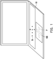
- FIG. 1 is a schematic diagram of an illuminated touchpad applied in an electronic device according to an embodiment of the disclosure.
- FIG. 2 is a schematic cross-sectional diagram of an illuminated touchpad according to an embodiment of the disclosure.
- an embodiment of the disclosure provides an illuminated touchpad 100, which is suitable for application in an electronic device 10.
- the electronic device 10 is, for example, a notebook computer, a smart phone or a keyboard, but the disclosure is not limited thereto.
- the illuminated touchpad 10 includes a protection layer 110, a touch module 120, and a Parallax-Barrier light source module 130.
- the protection layer 110 is, for example, a flat plate made of transparent materials such as plastic or glass. In an embodiment, the protection layer 110 may be a transparent plate under atomization treatment.
- the touch module 120 is disposed between the protection layer 110 and the Parallax-Barrier light source module 130.
- the Parallax-Barrier light source module 130 has a Parallax-Barrier pattern BPT or is used to produce the Parallax-Barrier pattern BPT.
- the Parallax-Barrier light source module 130 further has multiple patterns PT and produces multiple illuminated patterns IPT by the patterns PT, or the Parallax-Barrier light source module 130 directly produces the illuminated patterns IPT.
- the Parallax-Barrier pattern BPT lights from the illuminated pattern IPT pass through the touch module 120 and the protection layer 110 to form multiple stereoscopic images SI.
- the Parallax-Barrier light source module 130 includes a Parallax-Barrier pattern layer 131, a substrate 132, a pattern layer 133, a light guide layer 134, and a light source 135.
- the Parallax-Barrier pattern layer 131 includes the Parallax-Barrier pattern BPT.
- the Parallax-Barrier pattern layer 131 is disposed between the touch module 120 and the substrate 132.
- the pattern layer 133 is disposed on one side of the substrate 132 relative to the Parallax-Barrier pattern layer 131 and includes the pattern PT.
- the pattern layer 133 has a transparent area TA and a non-transparent area NTA.
- the pattern PT is disposed in the transparent area TA.
- the non-transparent area NTA may be in black opaque ink.
- a color of the non-transparent area NTA may be the same as a color of the electronic device 10 so that the illuminated touchpad 100 is visually consistent with the electronic device 10 when the illuminated touchpad 100 does not emit light.
- a light transmittance of the transparent area TA is preferably less than 70%.
- the light source 135 is, for example, a light-emitting diode (LED) light source or other suitable light source.
- the light source 135 is disposed next to the light guide layer 134 and used to emit an illumination beam IL.
- the pattern layer 133 is disposed between the substrate 132 and the light guide layer 134.
- the light guide layer 134 is, for example, a light guide film or a light guide plate.
- the illumination beam IL is first transmitted to the light guide layer 134, and then transmitted to the pattern PT by the light guide layer 134 to produce the illuminated pattern IPT.
- the light of the illuminated pattern IPT sequentially passes through the substrate 132, the Parallax-Barrier pattern layer 131, the touch module 120, and the protection layer 110 to form the stereoscopic image SI. That is to say, when the illumination beam IL is transmitted to the pre-designed pattern PT to produce the illuminated patterns IPT, the illuminated patterns IPT are transmitted to a left eye or a right eye of a viewer by the Parallax-Barrier pattern layer 131, so that the viewer may have the effect of seeing the stereoscopic image SI in visual.
- the stereoscopic image SI may be played, forward, backward, volume up, volume down, etc.
- the stereoscopic image SI may also be presented in a form of text.
- the illuminated touchpad 100 further includes a controller 140.
- the controller 140 is electrically connected to the touch module 120 and the Parallax-Barrier light source module 130.
- the controller 140 controls the Parallax-Barrier light source module 130 to produce the illuminated pattern IPT, and produces a corresponding function signal FS when a position P corresponding to the stereoscopic image SI on the illuminated touchpad 100 (the protection layer 110) is touched.
- the controller 140 includes, for example, a microcontroller unit (MCU), a central processing unit (CPU), a microprocessor, a digital signal processor (DSP), a programmable controller, a programmable logic device (PLD), or other similar devices, or combinations of these devices.
- MCU microcontroller unit
- CPU central processing unit
- DSP digital signal processor
- PLD programmable logic device
- each of the functions of the controller 140 may be implemented as multiple program codes.
- the program codes are stored in a memory, and the controller 140 executes the program codes.
- each of the functions of the controller 140 may be implemented as one or more circuits. The disclosure is not limited to implementing each function of the controller 140 in a way of software or hardware.
- the Parallax-Barrier pattern BPT has multiple slits SL.
- the illuminated touchpad 100 satisfies a relationship below: S'>S.
- S is a spacing between any two adjacent slits SL
- S' is a spacing between two patterns PT or two illuminated patterns IPT corresponding to the any two adjacent slits SL.
- the illuminated touchpad 100 further satisfies a relationship below: 1.00005 ⁇ S'/S ⁇ 1.005.
- the substrate 132 has a refractive index, such as the refractive index of 1.3.
- the light is refracted when passing through the substrate 132 (but in order to facilitate the explanation of the relationship between the spacings S and S', FIG. 2 simply illustrates that the light of the illuminated pattern IPT passes through the slit SL in a straight line and then is transmitted to the viewer). Therefore, the illuminated touchpad 100 needs to satisfy the relationship of S'>S.
- a thickness T of the substrate 132 for example, T ⁇ 0.6 mm
- the light- illuminated touchpad 100 preferably satisfies the relationship of 1.00005 ⁇ S'/S ⁇ 1.005.
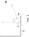
- FIG. 3 is a schematic diagram of a viewing angle of a stereoscopic image of an illuminated touchpad according to an embodiment of the disclosure.
- a viewing angle ⁇ of the stereoscopic image SI is less than or equal to 80 degrees.
- the illuminated touchpad 100 includes the protection layer 110, the touch module 120, and the Parallax-Barrier light source module 130.
- the Parallax-Barrier light source module 130 has the Parallax-Barrier pattern BPT or is used to produce the Parallax-Barrier pattern BPT.
- the Parallax-Barrier light source module 130 further has the patterns PT and produces the illuminated patterns IPT by the patterns PT, or the Parallax-Barrier light source module 130 directly produces the illuminated patterns IPT.
- the Parallax-Barrier pattern BPT the lights from the illuminated pattern IPT passes through the touch module 120 and the protection layer 110 to form the stereoscopic images SI.
- a system may present the stereoscopic image SI by emitting light, so that the user may still operate the illuminated touchpad 100 in a low-illumination environment. Moreover, the system may use the stereoscopic image SI to present operable actions or openable applications, thereby further enhancing the adaptability of the user for using the illuminated touchpad 100.
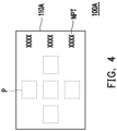
- FIG. 4 is a schematic diagram of an illuminated touchpad according to an embodiment of the disclosure.
- an illuminated touchpad 100A is similar to the illuminated touchpad 100 of FIG. 2 .
- the main differences are as follows.
- a protection layer 110A has multiple non-illuminated patterns NPT on the side relative to the touch module 120.
- the controller 140 produces the corresponding function signal FS.
- the non-illuminated pattern NPT may be a pattern or a name of a commonly used application (such as a browser, a calculator software, a video software, etc.).
- the system may open the corresponding application.
- FIG. 5 is a schematic cross-sectional diagram of an illuminated touchpad according to an embodiment of the disclosure.
- an illuminated touchpad 100B is similar to the illuminated touchpad 100 of FIG. 2 or the illuminated touchpad 100A of FIG. 4 .
- the main differences are as follows.
- a Parallax-Barrier light source module 130B includes the Parallax-Barrier pattern layer 131, the substrate 132, and a display module 136B.
- the display module 136B is, for example, a liquid crystal display, an organic light emitting diode (OLED) display, etc.
- OLED organic light emitting diode
- the display module 136B is disposed on one side of the substrate 132 relative to the Parallax-Barrier pattern layer 131 and is used to produce the illuminated pattern IPT.
- the lights of the illuminated pattern IPT sequentially pass through the substrate 132, the Parallax-Barrier pattern layer 131, the touch module 120, and the protection layer 110 to form the stereoscopic image SI. That is to say, the display module 136B may directly produce the illuminated pattern IPT. Therefore, the system may change the stereoscopic image SI produced by the illuminated touchpad 100B by changing the illuminated pattern IPT through the display module 136B; alternatively, the stereoscopic image SI produced by the illuminated touchpad 100B may be changed according to different applications opened in the system.
- FIG. 6 is a schematic cross-sectional diagram of an illuminated touchpad according to an embodiment of the disclosure.
- an illuminated touchpad 100C is similar to the illuminated touchpad 100B of FIG. 5 .
- the main differences are as follows.
- a Parallax-Barrier light source module 130C includes a display module 136C.
- the touch module 120 is disposed between the protection layer 110 and the display module 136C.
- the display module 136C is, for example, a 3D display.
- the display module 136C is used to produce the Parallax-Barrier pattern BPT and the illuminated pattern IPT.
- the display module 136C may not only directly produce the illuminated pattern IPT, but also produce the Parallax-Barrier pattern BPT. Moreover, in another embodiment, the display module 136C may further control the position of the illuminated pattern IPT or the position of the slit in the Parallax-Barrier pattern BPT. Therefore, the system may change the stereoscopic image SI produced by the illuminated touchpad 100C by changing the illuminated pattern; or, the stereoscopic image SI produced by the illuminated touchpad 100C may be changed according to different applications opened by the system.
- the illuminated touchpad includes the protection layer, the touch module, and the Parallax-Barrier light source module.
- the Parallax-Barrier light source module has the Parallax-Barrier pattern or is used to produce the Parallax-Barrier pattern.
- the Parallax-Barrier light source module further has the patterns and produces the illuminated patterns by the patterns, or the Parallax-Barrier light source module directly produces the illuminated patterns.
- the system may present the stereoscopic image by emitting light, allowing users to still operate the illuminated touchpad in the low-illumination environment.
- the system may use the stereoscopic images to present the operable actions or the openable applications, thereby further enhancing the adaptability of the user for using the illuminated touchpad.
Landscapes
- Engineering & Computer Science (AREA)
- General Engineering & Computer Science (AREA)
- Theoretical Computer Science (AREA)
- Physics & Mathematics (AREA)
- General Physics & Mathematics (AREA)
- Human Computer Interaction (AREA)
- Optics & Photonics (AREA)
- Position Input By Displaying (AREA)
Abstract
Disclosed are an illuminated touchpad (100) including a protection layer (110), a touch module (120), and a Parallax-Barrier light source module (130). The touch module (120) is disposed between the protection layer (110) and the Parallax-Barrier light source module (130). The Parallax-Barrier light source module (130) has a Parallax-Barrier pattern (BPT) or is used to produce the Parallax-Barrier pattern (BPT). The Parallax-Barrier light source module (130) further has multiple patterns (PT) and produces multiple illuminated patterns (IPT) by the patterns (PT), or the Parallax-Barrier light source module (130) directly produces the illuminated patterns (IPT). By the Parallax-Barrier pattern (BPT), lights of the illuminated patterns (IPT) pass through the touch module (120) and the protection layer (110) to form multiple stereoscopic images (SI).
Description
- The disclosure relates to a touchpad, and in particular to an illuminated touchpad.
- Touchpads have a wide range of applications in electronic products. For example, a touchpad may be applied to a smartphone to allow the user to quickly perform a set action or open a set application. Alternatively, the touchpad may be used in a notebook computer to replace the mouse function.
- To further enhance the convenience of the touchpad, application patterns may be set on the touchpad. When the application pattern is touched, the system will open the corresponding application. However, for users, there is still room for improvement in the design of touchpads currently on the market.
- The disclosure provides an illuminated touchpad, which may provide intuitive operational functions.
- An embodiment of the disclosure provides an illuminated touchpad, which includes a protection layer, a touch module, and a Parallax-Barrier light source module. The touch module is disposed between the protection layer and the Parallax-Barrier light source module. The Parallax-Barrier light source module has a Parallax-Barrier pattern or is used to produce the Parallax-Barrier pattern. The Parallax-Barrier light source module further has multiple patterns and produces multiple illuminated patterns by the patterns, or the Parallax-Barrier light source module directly produces the illuminated patterns. By the Parallax-Barrier pattern, lights of the illuminated pattern pass through the touch module and the protection layer to form multiple stereoscopic images.
- Based on the above, in the illuminated touchpad according to an embodiment of the disclosure, the Parallax-Barrier light source module has the Parallax-Barrier pattern or is used to produce the Parallax-Barrier pattern. The Parallax-Barrier light source module also has the patterns and produces the illuminated patterns through the patterns, or the Parallax-Barrier light source module directly produces the illuminated patterns. By the Parallax-Barrier pattern, the lights of the illuminated pattern pass through the touch module and the protection layer to form the stereoscopic images. Therefore, the system may present the stereoscopic image by emitting light, allowing users to still operate the illuminated touchpad in a low-illumination environment. Moreover, the system may use the stereoscopic images to present operable actions or openable applications, thereby further enhancing an adaptability for the user to using the illuminated touchpad.
-
-
FIG. 1 is a schematic diagram of an illuminated touchpad applied in an electronic device according to an embodiment of the disclosure. -
FIG. 2 is a schematic cross-sectional diagram of an illuminated touchpad according to an embodiment of the disclosure. -
FIG. 3 is a schematic diagram of a viewing angle of a stereoscopic image of an illuminated touchpad according to an embodiment of the disclosure. -
FIG. 4 is a schematic diagram of an illuminated touchpad according to an embodiment of the disclosure. -
FIG. 5 is a schematic cross-sectional diagram of an illuminated touchpad according to an embodiment of the disclosure. -
FIG. 6 is a schematic cross-sectional diagram of an illuminated touchpad according to an embodiment of the disclosure. -
FIG. 1 is a schematic diagram of an illuminated touchpad applied in an electronic device according to an embodiment of the disclosure.FIG. 2 is a schematic cross-sectional diagram of an illuminated touchpad according to an embodiment of the disclosure. Referring toFIGS. 1 and2 , an embodiment of the disclosure provides anilluminated touchpad 100, which is suitable for application in anelectronic device 10. Theelectronic device 10 is, for example, a notebook computer, a smart phone or a keyboard, but the disclosure is not limited thereto. - In this embodiment, the
illuminated touchpad 10 includes aprotection layer 110, atouch module 120, and a Parallax-Barrier light source module 130. Theprotection layer 110 is, for example, a flat plate made of transparent materials such as plastic or glass. In an embodiment, theprotection layer 110 may be a transparent plate under atomization treatment. - In this embodiment, the
touch module 120 is disposed between theprotection layer 110 and the Parallax-Barrier light source module 130. The Parallax-Barrier light source module 130 has a Parallax-Barrier pattern BPT or is used to produce the Parallax-Barrier pattern BPT. The Parallax-Barrier light source module 130 further has multiple patterns PT and produces multiple illuminated patterns IPT by the patterns PT, or the Parallax-Barrier light source module 130 directly produces the illuminated patterns IPT. By the Parallax-Barrier pattern BPT, lights from the illuminated pattern IPT pass through thetouch module 120 and theprotection layer 110 to form multiple stereoscopic images SI. - Specifically, in this embodiment, the Parallax-Barrier light source module 130 includes a Parallax-
Barrier pattern layer 131, asubstrate 132, apattern layer 133, alight guide layer 134, and alight source 135. The Parallax-Barrier pattern layer 131 includes the Parallax-Barrier pattern BPT. The Parallax-Barrier pattern layer 131 is disposed between thetouch module 120 and thesubstrate 132. Thepattern layer 133 is disposed on one side of thesubstrate 132 relative to the Parallax-Barrierpattern layer 131 and includes the pattern PT. Thepattern layer 133 has a transparent area TA and a non-transparent area NTA. The pattern PT is disposed in the transparent area TA. - For example, the non-transparent area NTA may be in black opaque ink. Alternatively, a color of the non-transparent area NTA may be the same as a color of the
electronic device 10 so that theilluminated touchpad 100 is visually consistent with theelectronic device 10 when theilluminated touchpad 100 does not emit light. - In order to improve the visual consistency between the
illuminated touchpad 100 and theelectronic device 10 when theilluminated touchpad 100 does not emit light, in this embodiment, a light transmittance of the transparent area TA is preferably less than 70%. - In this embodiment, the
light source 135 is, for example, a light-emitting diode (LED) light source or other suitable light source. Thelight source 135 is disposed next to thelight guide layer 134 and used to emit an illumination beam IL. Thepattern layer 133 is disposed between thesubstrate 132 and thelight guide layer 134. Thelight guide layer 134 is, for example, a light guide film or a light guide plate. The illumination beam IL is first transmitted to thelight guide layer 134, and then transmitted to the pattern PT by thelight guide layer 134 to produce the illuminated pattern IPT. The light of the illuminated pattern IPT sequentially passes through thesubstrate 132, the Parallax-Barrier pattern layer 131, thetouch module 120, and theprotection layer 110 to form the stereoscopic image SI. That is to say, when the illumination beam IL is transmitted to the pre-designed pattern PT to produce the illuminated patterns IPT, the illuminated patterns IPT are transmitted to a left eye or a right eye of a viewer by the Parallax-Barrier pattern layer 131, so that the viewer may have the effect of seeing the stereoscopic image SI in visual. TakingFIG. 1 as an example, the stereoscopic image SI may be played, forward, backward, volume up, volume down, etc. In another embodiment, the stereoscopic image SI may also be presented in a form of text. - In this embodiment, the
illuminated touchpad 100 further includes acontroller 140. Thecontroller 140 is electrically connected to thetouch module 120 and the Parallax-Barrier light source module 130. Thecontroller 140 controls the Parallax-Barrier light source module 130 to produce the illuminated pattern IPT, and produces a corresponding function signal FS when a position P corresponding to the stereoscopic image SI on the illuminated touchpad 100 (the protection layer 110) is touched. - In this embodiment, the
controller 140 includes, for example, a microcontroller unit (MCU), a central processing unit (CPU), a microprocessor, a digital signal processor (DSP), a programmable controller, a programmable logic device (PLD), or other similar devices, or combinations of these devices. The disclosure is not limited thereto. In addition, in an embodiment, each of the functions of thecontroller 140 may be implemented as multiple program codes. The program codes are stored in a memory, and thecontroller 140 executes the program codes. Alternatively, in an embodiment, each of the functions of thecontroller 140 may be implemented as one or more circuits. The disclosure is not limited to implementing each function of thecontroller 140 in a way of software or hardware. - In this embodiment, the Parallax-Barrier pattern BPT has multiple slits SL. The
illuminated touchpad 100 satisfies a relationship below: S'>S. S is a spacing between any two adjacent slits SL, and S' is a spacing between two patterns PT or two illuminated patterns IPT corresponding to the any two adjacent slits SL. - In this embodiment, the illuminated
touchpad 100 further satisfies a relationship below: 1.00005≤S'/S≤1.005. - For example, the
substrate 132 has a refractive index, such as the refractive index of 1.3. The light is refracted when passing through the substrate 132 (but in order to facilitate the explanation of the relationship between the spacings S and S',FIG. 2 simply illustrates that the light of the illuminated pattern IPT passes through the slit SL in a straight line and then is transmitted to the viewer). Therefore, the illuminatedtouchpad 100 needs to satisfy the relationship of S'>S. Further considering a thickness T of thesubstrate 132, for example, T<0.6 mm, the light- illuminatedtouchpad 100 preferably satisfies the relationship of 1.00005≤S'/S≤1.005. -
FIG. 3 is a schematic diagram of a viewing angle of a stereoscopic image of an illuminated touchpad according to an embodiment of the disclosure. Referring toFIG. 3 , in this embodiment, a viewing angle θ of the stereoscopic image SI is less than or equal to 80 degrees. - Based on the above, in an embodiment of the disclosure, the illuminated
touchpad 100 includes theprotection layer 110, thetouch module 120, and the Parallax-Barrier light source module 130. The Parallax-Barrier light source module 130 has the Parallax-Barrier pattern BPT or is used to produce the Parallax-Barrier pattern BPT. The Parallax-Barrier light source module 130 further has the patterns PT and produces the illuminated patterns IPT by the patterns PT, or the Parallax-Barrier light source module 130 directly produces the illuminated patterns IPT. By the Parallax-Barrier pattern BPT, the lights from the illuminated pattern IPT passes through thetouch module 120 and theprotection layer 110 to form the stereoscopic images SI. Therefore, a system may present the stereoscopic image SI by emitting light, so that the user may still operate the illuminatedtouchpad 100 in a low-illumination environment. Moreover, the system may use the stereoscopic image SI to present operable actions or openable applications, thereby further enhancing the adaptability of the user for using the illuminatedtouchpad 100. -
FIG. 4 is a schematic diagram of an illuminated touchpad according to an embodiment of the disclosure. Referring toFIG. 4 , anilluminated touchpad 100A is similar to the illuminatedtouchpad 100 ofFIG. 2 . The main differences are as follows. In this embodiment, aprotection layer 110A has multiple non-illuminated patterns NPT on the side relative to thetouch module 120. When the position corresponding to the non-illuminated pattern NPT on the illuminatedtouchpad 100A (theprotection layer 110A) is touched, thecontroller 140 produces the corresponding function signal FS. For example, the non-illuminated pattern NPT may be a pattern or a name of a commonly used application (such as a browser, a calculator software, a video software, etc.). When the user touches the non-illuminated pattern NPT, the system may open the corresponding application. -
FIG. 5 is a schematic cross-sectional diagram of an illuminated touchpad according to an embodiment of the disclosure. Referring toFIG. 5 , anilluminated touchpad 100B is similar to the illuminatedtouchpad 100 ofFIG. 2 or theilluminated touchpad 100A ofFIG. 4 . The main differences are as follows. In this embodiment, a Parallax-Barrier light source module 130B includes the Parallax-Barrier pattern layer 131, thesubstrate 132, and adisplay module 136B. Thedisplay module 136B is, for example, a liquid crystal display, an organic light emitting diode (OLED) display, etc. Thedisplay module 136B is disposed on one side of thesubstrate 132 relative to the Parallax-Barrier pattern layer 131 and is used to produce the illuminated pattern IPT. The lights of the illuminated pattern IPT sequentially pass through thesubstrate 132, the Parallax-Barrier pattern layer 131, thetouch module 120, and theprotection layer 110 to form the stereoscopic image SI. That is to say, thedisplay module 136B may directly produce the illuminated pattern IPT. Therefore, the system may change the stereoscopic image SI produced by the illuminatedtouchpad 100B by changing the illuminated pattern IPT through thedisplay module 136B; alternatively, the stereoscopic image SI produced by the illuminatedtouchpad 100B may be changed according to different applications opened in the system. -
FIG. 6 is a schematic cross-sectional diagram of an illuminated touchpad according to an embodiment of the disclosure. Referring toFIG. 6 , anilluminated touchpad 100C is similar to the illuminatedtouchpad 100B ofFIG. 5 . The main differences are as follows. In this embodiment, a Parallax-Barrier light source module 130C includes adisplay module 136C. Thetouch module 120 is disposed between theprotection layer 110 and thedisplay module 136C. Thedisplay module 136C is, for example, a 3D display. Thedisplay module 136C is used to produce the Parallax-Barrier pattern BPT and the illuminated pattern IPT. By the Parallax-Barrier pattern BPT, the lights from the illuminated pattern IPT sequentially pass through thetouch module 120 and theprotection layer 110 to form the stereoscopic image SI. That is to say, thedisplay module 136C may not only directly produce the illuminated pattern IPT, but also produce the Parallax-Barrier pattern BPT. Moreover, in another embodiment, thedisplay module 136C may further control the position of the illuminated pattern IPT or the position of the slit in the Parallax-Barrier pattern BPT. Therefore, the system may change the stereoscopic image SI produced by the illuminatedtouchpad 100C by changing the illuminated pattern; or, the stereoscopic image SI produced by the illuminatedtouchpad 100C may be changed according to different applications opened by the system. - To sum up, in an embodiment of the disclosure, the illuminated touchpad includes the protection layer, the touch module, and the Parallax-Barrier light source module. The Parallax-Barrier light source module has the Parallax-Barrier pattern or is used to produce the Parallax-Barrier pattern. The Parallax-Barrier light source module further has the patterns and produces the illuminated patterns by the patterns, or the Parallax-Barrier light source module directly produces the illuminated patterns. By the Parallax-Barrier pattern, the lights of the illuminated pattern pass through the touch module and the protection layer to form the stereoscopic images. Therefore, the system may present the stereoscopic image by emitting light, allowing users to still operate the illuminated touchpad in the low-illumination environment. Moreover, the system may use the stereoscopic images to present the operable actions or the openable applications, thereby further enhancing the adaptability of the user for using the illuminated touchpad.
Claims (12)
- An illuminated touchpad (100), comprising:a protection layer (110);a touch module (120); anda Parallax-Barrier light source module (130), wherein the touch module (120) is disposed between the protection layer (110) and the Parallax-Barrier light source module (130), the Parallax-Barrier light source module (130) has a Parallax-Barrier pattern (BPT) or is disposed to produce the Parallax-Barrier pattern (BPT), the Parallax-Barrier light source module (130) further has a plurality of patterns (PT) and produces a plurality of illuminated patterns (IPT) by the plurality of patterns (PT), or the Parallax-Barrier light source module (130) directly produces the plurality of illuminated patterns (IPT),wherein by the Parallax-Barrier pattern (BPT), lights of the plurality of illuminated patterns (IPT) pass through the touch module (120) and the protection layer (110) to form a plurality of stereoscopic images (SI).
- The illuminated touchpad (100) according to claim 1, further comprising:a controller (140), electrically connected to the touch module (120) and the Parallax-Barrier light source module (130),wherein the controller (140) controls the Parallax-Barrier light source module (130) to produce the plurality of illuminated patterns (IPT), and produces corresponding function signals (FS) in response to a position corresponding to the plurality of stereoscopic images (SI) on the illuminated touchpad (100) being touched.
- The illuminated touchpad (100) according to claim 1, wherein a viewing angle of the plurality of stereoscopic images (SI) is less than or equal to 80 degrees.
- The illuminated touchpad (100) according to claim 1, wherein the Parallax-Barrier pattern (BPT) has a plurality of slits (SL), wherein:

- The illuminated touchpad (100) according to claim 1, wherein the Parallax-Barrier pattern (BPT) has a plurality of slits (SL), wherein:

- The illuminated touchpad (100) according to claim 1, wherein the Parallax-Barrier light source module (130) comprises:a Parallax-Barrier pattern layer (131), comprising the Parallax-Barrier pattern (BPT);a substrate (132), wherein the Parallax-Barrier pattern layer (131) is disposed between the touch module (120) and the substrate (132);a pattern layer (133), disposed on one side of the substrate (132) relative to the Parallax-Barrier pattern layer (131), and comprising the plurality of patterns (PT);a light guide layer (134), wherein the pattern layer (133) is disposed between the substrate (132) and the light guide layer (134); anda light source (135), disposed next to the light guide layer (134) and disposed to emit an illumination beam (IL),wherein the light of the illumination beam (IL) is first transmitted to the light guide layer (134), and then transmitted to the plurality of patterns (PT) by the light guide layer (134) to produce the plurality of illuminated patterns (IPT), the plurality of illuminated patterns (IPT) sequentially pass through the substrate (132), the Parallax-Barrier pattern layer (131), the touch module (120), and the protection layer (110) to form the plurality of the stereoscopic images (SI).
- The illuminated touchpad (100) according to claim 6, wherein the pattern layer (133) has a transparent area (TA) and a non-transparent area (NTA), and the plurality of patterns (PT) are disposed in the transparent area (TA).
- The illuminated touchpad (100) according to claim 7, wherein a light transmittance of the transparent area (TA) is less than 70%.
- The illuminated touchpad (100) according to claim 1, wherein the Parallax-Barrier light source module (130) comprises:a Parallax-Barrier pattern layer (131), comprising the Parallax-Barrier pattern (BPT);a substrate (132), wherein the Parallax-Barrier pattern layer (131) is disposed between the touch module (120) and the substrate (132); anda display module (136B), disposed on one side of the substrate (132) relative to the Parallax-Barrier pattern layer (131) and disposed to produce the plurality of illuminated patterns (IPT),wherein the lights of the plurality of illuminated patterns (IPT) sequentially pass through the substrate (132), the Parallax-Barrier pattern layer (131), the touch module (120), and the protection layer (110) to form the plurality of stereoscopic images (SI).
- The illuminated touchpad (100) according to claim 1, wherein the Parallax-Barrier light source module (130) comprises:a display module (136B), wherein the touch module (120) is disposed between the protection layer (110) and the display module (136B), and the display module (136B) is disposed to produce the Parallax-Barrier pattern (BPT) and the plurality of illuminated patterns (IPT),wherein by the Parallax-Barrier pattern (BPT), the lights of the plurality of illuminated patterns (IPT) sequentially pass through the touch module (120) and the protection layer (110) to form the plurality of stereoscopic images (SI).
- The illuminated touchpad (100) according to claim 1, wherein the protection layer (110) has a plurality of non-illuminated patterns on one side relative to the touch module (120).
- The illuminated touchpad (100) according to claim 11, further comprising:a controller (140), electrically connected to the touch module (120),wherein in response to a position corresponding to the plurality of non-illuminated patterns on the illuminated touchpad (100) being touched, the controller (140) produces corresponding function signals (FS).
Applications Claiming Priority (1)
| Application Number | Priority Date | Filing Date | Title |
|---|---|---|---|
| TW112142134A TWI879201B (en) | 2023-11-02 | 2023-11-02 | Illuminated touchpad |
Publications (1)
| Publication Number | Publication Date |
|---|---|
| EP4550098A1 true EP4550098A1 (en) | 2025-05-07 |
Family
ID=90057409
Family Applications (1)
| Application Number | Title | Priority Date | Filing Date |
|---|---|---|---|
| EP24159437.3A Pending EP4550098A1 (en) | 2023-11-02 | 2024-02-23 | Illuminated touchpad |
Country Status (3)
| Country | Link |
|---|---|
| US (1) | US12547279B2 (en) |
| EP (1) | EP4550098A1 (en) |
| TW (1) | TWI879201B (en) |
Citations (3)
| Publication number | Priority date | Publication date | Assignee | Title |
|---|---|---|---|---|
| EP2346021A1 (en) * | 2009-12-31 | 2011-07-20 | Broadcom Corporation | Frame formatting supporting mixed two and three dimensional video data communication |
| US20130100124A1 (en) * | 2011-10-25 | 2013-04-25 | Lg Electronics Inc. | Display module and mobile terminal having the same |
| KR20160103769A (en) * | 2015-02-25 | 2016-09-02 | 크루셜텍 (주) | Three dimensional display apparatus with improved visualbility and touch detecting |
Family Cites Families (18)
| Publication number | Priority date | Publication date | Assignee | Title |
|---|---|---|---|---|
| US20070152983A1 (en) * | 2005-12-30 | 2007-07-05 | Apple Computer, Inc. | Touch pad with symbols based on mode |
| TWI384388B (en) * | 2007-12-25 | 2013-02-01 | 宏碁股份有限公司 | Method for displaying step size by light, touch sensing operation interface device and portable electronic device |
| GB2457691A (en) * | 2008-02-21 | 2009-08-26 | Sharp Kk | Display with regions simultaneously operable in different viewing modes |
| TWI409677B (en) | 2008-11-28 | 2013-09-21 | Elan Microelectronics Corp | Illuminated touchpad module and illuminated device thereof |
| JP5563250B2 (en) * | 2009-06-30 | 2014-07-30 | 株式会社ジャパンディスプレイ | Stereoscopic image display device |
| TWI474299B (en) * | 2010-08-05 | 2015-02-21 | Display device and method for manufacturing parallax barrier touch plate | |
| TWI422865B (en) * | 2010-10-28 | 2014-01-11 | Au Optronics Corp | Switchable three-dimensional display |
| TWI432781B (en) * | 2011-01-26 | 2014-04-01 | 瀚宇彩晶股份有限公司 | Display device, parallax barrier touch panel and manufacturing method thereof |
| JP5596625B2 (en) * | 2011-06-07 | 2014-09-24 | 株式会社ジャパンディスプレイ | Display device |
| KR20130096050A (en) * | 2012-02-21 | 2013-08-29 | 삼성디스플레이 주식회사 | Display device |
| CN103324001B (en) * | 2013-05-24 | 2016-03-16 | 北京京东方光电科技有限公司 | A kind of touch bore hole 3D grating and display device |
| KR102070811B1 (en) * | 2013-06-17 | 2020-01-30 | 삼성전자주식회사 | Display apparatus and touch panel |
| TWI522856B (en) * | 2013-07-25 | 2016-02-21 | 恆顥科技股份有限公司 | Touch panel, touch sensor and method for manufacturingthe same |
| TWI493408B (en) * | 2013-08-01 | 2015-07-21 | Au Optronics Corp | Optical switching device and stereoscopic display device integrated with touch structure |
| TWI598636B (en) * | 2014-05-23 | 2017-09-11 | 宇勤科技(深圳)有限公司 | Stereoscopic image displayer |
| GB2527548A (en) * | 2014-06-25 | 2015-12-30 | Sharp Kk | Variable barrier pitch correction |
| CN104730719B (en) * | 2015-04-09 | 2017-03-15 | 京东方科技集团股份有限公司 | Touch-control bore hole grating 3D display devices and its preparation and control method |
| JP2019185169A (en) * | 2018-04-03 | 2019-10-24 | 富士通コンポーネント株式会社 | Input device |
-
2023
- 2023-11-02 TW TW112142134A patent/TWI879201B/en active
-
2024
- 2024-01-19 US US18/416,914 patent/US12547279B2/en active Active
- 2024-02-23 EP EP24159437.3A patent/EP4550098A1/en active Pending
Patent Citations (3)
| Publication number | Priority date | Publication date | Assignee | Title |
|---|---|---|---|---|
| EP2346021A1 (en) * | 2009-12-31 | 2011-07-20 | Broadcom Corporation | Frame formatting supporting mixed two and three dimensional video data communication |
| US20130100124A1 (en) * | 2011-10-25 | 2013-04-25 | Lg Electronics Inc. | Display module and mobile terminal having the same |
| KR20160103769A (en) * | 2015-02-25 | 2016-09-02 | 크루셜텍 (주) | Three dimensional display apparatus with improved visualbility and touch detecting |
Also Published As
| Publication number | Publication date |
|---|---|
| US12547279B2 (en) | 2026-02-10 |
| TW202520047A (en) | 2025-05-16 |
| TWI879201B (en) | 2025-04-01 |
| US20250147627A1 (en) | 2025-05-08 |
Similar Documents
| Publication | Publication Date | Title |
|---|---|---|
| US10877570B1 (en) | Electronic devices having keys with coherent fiber bundles | |
| TWI631496B (en) | Electronic device and touch panel | |
| CN101751176A (en) | Light-emitting touch control panel module | |
| CN109765724B (en) | A liquid crystal display module and mobile terminal | |
| TW201419063A (en) | Touch display | |
| CN103672741A (en) | Light guide module and electronic device | |
| JPWO2014103274A1 (en) | Display control system and reader | |
| US20110273403A1 (en) | Photo-sensing lcd touch device | |
| TW201445403A (en) | Multifunction input device | |
| TW201419062A (en) | Touch display | |
| KR20140057047A (en) | Touch screen panel and portable electronic apparatus having the same | |
| TW200945113A (en) | Light-emitting module and keyboard having the same | |
| US11914809B2 (en) | Illuminated trackpad | |
| US12547279B2 (en) | Illuminated touchpad having parallax barrier light source module | |
| KR20150106232A (en) | A touch recognition device and display applying the same | |
| TWI885527B (en) | Illuminated touchpad | |
| CN109729200B (en) | Electronic device | |
| CN120020682A (en) | Illuminated touchpad | |
| CN205862311U (en) | Touch panel with light emitting device and electronic device | |
| CN103309542A (en) | Multifunctional input equipment | |
| TWI734573B (en) | Image display device | |
| CN119902636A (en) | Illuminated touchpad | |
| TWI663537B (en) | Optical touch device capable of defining pen color and method thereof | |
| CN201174123Y (en) | Touch control panel structure | |
| CN217821993U (en) | Graphic display structure and portable electronic device |
Legal Events
| Date | Code | Title | Description |
|---|---|---|---|
| PUAI | Public reference made under article 153(3) epc to a published international application that has entered the european phase |
Free format text: ORIGINAL CODE: 0009012 |
|
| STAA | Information on the status of an ep patent application or granted ep patent |
Free format text: STATUS: THE APPLICATION HAS BEEN PUBLISHED |
|
| AK | Designated contracting states |
Kind code of ref document: A1 Designated state(s): AL AT BE BG CH CY CZ DE DK EE ES FI FR GB GR HR HU IE IS IT LI LT LU LV MC ME MK MT NL NO PL PT RO RS SE SI SK SM TR |
|
| STAA | Information on the status of an ep patent application or granted ep patent |
Free format text: STATUS: REQUEST FOR EXAMINATION WAS MADE |
|
| 17P | Request for examination filed |
Effective date: 20250902 |