EP4550055A1 - Developer cartridge - Google Patents
Developer cartridge Download PDFInfo
- Publication number
- EP4550055A1 EP4550055A1 EP23831202.9A EP23831202A EP4550055A1 EP 4550055 A1 EP4550055 A1 EP 4550055A1 EP 23831202 A EP23831202 A EP 23831202A EP 4550055 A1 EP4550055 A1 EP 4550055A1
- Authority
- EP
- European Patent Office
- Prior art keywords
- shaft
- cam
- casing
- developing
- developing cartridge
- Prior art date
- Legal status (The legal status is an assumption and is not a legal conclusion. Google has not performed a legal analysis and makes no representation as to the accuracy of the status listed.)
- Pending
Links
Images






Classifications
-
- G—PHYSICS
- G03—PHOTOGRAPHY; CINEMATOGRAPHY; ANALOGOUS TECHNIQUES USING WAVES OTHER THAN OPTICAL WAVES; ELECTROGRAPHY; HOLOGRAPHY
- G03G—ELECTROGRAPHY; ELECTROPHOTOGRAPHY; MAGNETOGRAPHY
- G03G21/00—Arrangements not provided for by groups G03G13/00 - G03G19/00, e.g. cleaning, elimination of residual charge
- G03G21/16—Mechanical means for facilitating the maintenance of the apparatus, e.g. modular arrangements
- G03G21/1661—Mechanical means for facilitating the maintenance of the apparatus, e.g. modular arrangements means for handling parts of the apparatus in the apparatus
- G03G21/1676—Mechanical means for facilitating the maintenance of the apparatus, e.g. modular arrangements means for handling parts of the apparatus in the apparatus for the developer unit
-
- G—PHYSICS
- G03—PHOTOGRAPHY; CINEMATOGRAPHY; ANALOGOUS TECHNIQUES USING WAVES OTHER THAN OPTICAL WAVES; ELECTROGRAPHY; HOLOGRAPHY
- G03G—ELECTROGRAPHY; ELECTROPHOTOGRAPHY; MAGNETOGRAPHY
- G03G15/00—Apparatus for electrographic processes using a charge pattern
- G03G15/06—Apparatus for electrographic processes using a charge pattern for developing
- G03G15/08—Apparatus for electrographic processes using a charge pattern for developing using a solid developer, e.g. powder developer
- G03G15/0806—Apparatus for electrographic processes using a charge pattern for developing using a solid developer, e.g. powder developer on a donor element, e.g. belt, roller
- G03G15/0813—Apparatus for electrographic processes using a charge pattern for developing using a solid developer, e.g. powder developer on a donor element, e.g. belt, roller characterised by means in the developing zone having an interaction with the image carrying member, e.g. distance holders
-
- G—PHYSICS
- G03—PHOTOGRAPHY; CINEMATOGRAPHY; ANALOGOUS TECHNIQUES USING WAVES OTHER THAN OPTICAL WAVES; ELECTROGRAPHY; HOLOGRAPHY
- G03G—ELECTROGRAPHY; ELECTROPHOTOGRAPHY; MAGNETOGRAPHY
- G03G15/00—Apparatus for electrographic processes using a charge pattern
- G03G15/06—Apparatus for electrographic processes using a charge pattern for developing
- G03G15/08—Apparatus for electrographic processes using a charge pattern for developing using a solid developer, e.g. powder developer
- G03G15/0896—Arrangements or disposition of the complete developer unit or parts thereof not provided for by groups G03G15/08 - G03G15/0894
-
- G—PHYSICS
- G03—PHOTOGRAPHY; CINEMATOGRAPHY; ANALOGOUS TECHNIQUES USING WAVES OTHER THAN OPTICAL WAVES; ELECTROGRAPHY; HOLOGRAPHY
- G03G—ELECTROGRAPHY; ELECTROPHOTOGRAPHY; MAGNETOGRAPHY
- G03G15/00—Apparatus for electrographic processes using a charge pattern
- G03G15/06—Apparatus for electrographic processes using a charge pattern for developing
- G03G15/08—Apparatus for electrographic processes using a charge pattern for developing using a solid developer, e.g. powder developer
- G03G15/0822—Arrangements for preparing, mixing, supplying or dispensing developer
- G03G15/0863—Arrangements for preparing, mixing, supplying or dispensing developer provided with identifying means or means for storing process- or use parameters, e.g. an electronic memory
-
- G—PHYSICS
- G03—PHOTOGRAPHY; CINEMATOGRAPHY; ANALOGOUS TECHNIQUES USING WAVES OTHER THAN OPTICAL WAVES; ELECTROGRAPHY; HOLOGRAPHY
- G03G—ELECTROGRAPHY; ELECTROPHOTOGRAPHY; MAGNETOGRAPHY
- G03G21/00—Arrangements not provided for by groups G03G13/00 - G03G19/00, e.g. cleaning, elimination of residual charge
- G03G21/16—Mechanical means for facilitating the maintenance of the apparatus, e.g. modular arrangements
- G03G21/1642—Mechanical means for facilitating the maintenance of the apparatus, e.g. modular arrangements for connecting the different parts of the apparatus
- G03G21/1647—Mechanical connection means
-
- G—PHYSICS
- G03—PHOTOGRAPHY; CINEMATOGRAPHY; ANALOGOUS TECHNIQUES USING WAVES OTHER THAN OPTICAL WAVES; ELECTROGRAPHY; HOLOGRAPHY
- G03G—ELECTROGRAPHY; ELECTROPHOTOGRAPHY; MAGNETOGRAPHY
- G03G21/00—Arrangements not provided for by groups G03G13/00 - G03G19/00, e.g. cleaning, elimination of residual charge
- G03G21/16—Mechanical means for facilitating the maintenance of the apparatus, e.g. modular arrangements
- G03G21/18—Mechanical means for facilitating the maintenance of the apparatus, e.g. modular arrangements using a processing cartridge, whereby the process cartridge comprises at least two image processing means in a single unit
- G03G21/1803—Arrangements or disposition of the complete process cartridge or parts thereof
- G03G21/1817—Arrangements or disposition of the complete process cartridge or parts thereof having a submodular arrangement
- G03G21/1821—Arrangements or disposition of the complete process cartridge or parts thereof having a submodular arrangement means for connecting the different parts of the process cartridge, e.g. attachment, positioning of parts with each other, pressure/distance regulation
-
- G—PHYSICS
- G03—PHOTOGRAPHY; CINEMATOGRAPHY; ANALOGOUS TECHNIQUES USING WAVES OTHER THAN OPTICAL WAVES; ELECTROGRAPHY; HOLOGRAPHY
- G03G—ELECTROGRAPHY; ELECTROPHOTOGRAPHY; MAGNETOGRAPHY
- G03G2221/00—Processes not provided for by group G03G2215/00, e.g. cleaning or residual charge elimination
- G03G2221/16—Mechanical means for facilitating the maintenance of the apparatus, e.g. modular arrangements and complete machine concepts
- G03G2221/163—Mechanical means for facilitating the maintenance of the apparatus, e.g. modular arrangements and complete machine concepts for the developer unit
Definitions
- the present disclosure relates to a developing cartridge.
- the image-forming apparatus described in Patent literature 1 includes a developing cartridge and a drum cartridge.
- the developing cartridge includes a developing roller.
- the drum cartridge includes a photosensitive drum. The developing roller contacts the photosensitive drum upon attachment of the developing cartridge to the drum cartridge.
- the image-forming apparatus described in Patent literature 1 further includes a separation member.
- the separation member is movable relative to a casing of the developing cartridge. Once the separation member is moved in a state where the developing cartridge is attached to the drum cartridge, the separation member contacts a frame of the drum cartridge. Hence, the developing cartridge is moved relative to the drum cartridge. As a result, the developing roller can be separated from the photosensitive drum.
- the separation member is positioned, among outer surfaces of the casing of the developing cartridge, on a surface that is on the same side as the developing roller (the outer surface of a lid 10B in Patent literature).
- the separation member it is hard to arrange the separation member in line with a center of gravity of the developing cartridge in a separating direction. Accordingly, a larger load is likely to be imparted on the separation member in order to move the developing cartridge in the separating direction.
- a first aspect of the disclosure provides a developing cartridge including: a casing configured store developing agent therein; a developing roller rotatable about a first axis extending in a first direction; a shaft extending along a second axis extending in the first direction; and a first cam positioned at one end portion of the shaft in the first direction, wherein a part of a peripheral surface of the developing roller on one side in a second direction is exposed to an outside of the casing and another part of the peripheral surface of the developing roller on an other side in the second direction is positioned inside the casing; the developing roller is positioned at one end portion of the casing in a third direction crossing the first direction and the second direction; the shaft is movable in the first direction relative to the casing and the developing roller; the first cam is movable in the first direction together with the shaft; and the first cam has a first inclined surface that is inclined to approach the developing roller in the second direction as extending toward the one end portion of the shaft from an other
- a second aspect of the disclosure provides the developing cartridge according to the first aspect that further includes an agitator rotatable about a third axis extending in the first direction and including an agitator shaft extending in the first direction.
- the developing cartridge is characterized in that the shaft and the first cam are positioned opposite the developing roller with respect to the agitator shaft in the third direction.
- a third aspect of the disclosure provides the developing cartridge according to the first or the second aspect which is characterized in that the shaft is aligned with a center of gravity of the developing cartridge in the second direction.
- a fourth aspect of the disclosure provides the developing cartridge according to any one of the first through third aspects which is characterized in that the casing has: a first outer surface positioned on the same side as the developing roller in the third direction; and a second outer surface positioned on the same side as the shaft and the first cam in the third direction.
- a fifth aspect of the disclosure provides the developing cartridge according to the fourth aspect which is characterized in that the first cam is positioned between the first outer surface and the second outer surface in the third direction.
- a sixth aspect of the disclosure provides the developing cartridge according to the fourth or fifth aspect which is characterized in that the first cam is positioned at the second outer surface.
- a seventh aspect of the disclosure provides the developing cartridge according to the sixth aspect which is characterized in that: the second outer surface has a groove extending in the first direction; and the shaft is positioned in the groove.
- the developing cartridge of the sixth or seventh aspect is characterized in that: the casing includes a rib protruding from the second outer surface; and the shaft is positioned between the second outer surface and the rib in the second direction.
- a ninth aspect of the disclosure provides the developing cartridge according to any one of the first through eighth aspects which is characterized by further including a resilient member configured to expand and compress in the first direction and positioned between the casing and the first cam in the first direction.
- a tenth aspect of the disclosure provides the developing cartridge according to any one of the first through ninth aspects which is characterized by further including a gear cover positioned at the one end portion of the casing in the first direction, and in that the first cam is held by the gear cover.
- An eleventh aspect of the disclosure provides the developing cartridge according to the tenth aspect which is characterized in that: the gear cover has a first through-hole penetrating the gear cover in the first direction; and the first cam is inserted in the first through-hole.
- the developing cartridge according to any one of the first through eleventh aspects which is characterized by further including a second cam positioned at the other end portion of the shaft in the first direction and movable in the first direction together with the shaft, the second cam having a second inclined surface that is inclined to approach the developing roller in the second direction as extending toward the one end portion of the shaft from the other end portion of the shaft in the first direction, the second cam being positioned at the other end portion of the casing in the third direction.
- a thirteenth aspect of the disclosure provides the developing cartridge according to the twelfth aspect which is characterized by further including a holder cover positioned at an other end portion of the casing in the first direction, the second cam being held by the holder cover.
- a fourteenth aspect of the disclosure provides the developing cartridge according to the thirteenth aspect which is characterized in that the holder cover has a second through-hole penetrating the holder cover in the first direction, the second cam being inserted in the second through-hole.
- a fifteenth aspect of the disclosure provides the developing cartridge according to the thirteenth or fourteenth aspect which is characterized by further including: a storage medium having an electrical contact surface; and a holder holding the electrical contact surface, the holder being positioned between the casing and the holder cover in the first direction, the shaft and the first cam being positioned opposite the developing roller with respect to the holder in the third direction.
- a sixteenth aspect of the disclosure provides the developing cartridge according to any one of the first through fifteenth aspects which is characterized in that: the casing has a toner filling port; and the shaft and the first cam are positioned opposite the developing roller with respect to the toner filling port in the third direction.
- a seventeenth aspect of the disclosure provides the developing cartridge according to any one of the first through sixteenth aspects which is characterized in that the shaft and the first cam are integrally molded with resin.
- An eighteenth aspect of the disclosure provides the developing cartridge according to any one of the first through seventeenth aspects which is characterized by further including a storage medium having an electrical contact surface, the third direction crossing the electrical contact surface.
- the shaft and the first cam are positioned opposite the developing roller in the third direction.
- the shaft can be arranged closer to a position aligned with the center of gravity of the developing cartridge in the second direction. Accordingly, a load to be imparted on the shaft for moving the developing cartridge in the second direction can be reduced.
- the load to be imparted on the shaft for moving the developing cartridge in the second direction in a separating operation can be reduced.
- the positional displacement of the shaft can be restrained by positioning the shaft in the groove.
- the casing is made movable relative to the drum cartridge in the second direction by the pressure applied from the shaft to the rib in the second direction in the separating operation.
- first direction a direction in which a first axis of a developing roller 30 extends
- second direction a direction in which, of a peripheral surface of the developing roller 30, a part exposed to an outside from a casing 10 and a part positioned inside the casing 10 are aligned with each other
- third direction a direction crossing the first direction and the second direction
- the first direction and the second direction cross each other (preferably, perpendicular to each other).
- the second direction and the third direction cross each other.
- the third direction and the first direction cross each other (preferably, perpendicular to each other).
- Fig. 1 is a schematic view of an image-forming apparatus 100.
- the image-forming apparatus 100 is an electrophotographic type printer. Specifically, the image-forming apparatus 100 is a laser printer or an LED printer. As illustrated in Fig. 1 , the image-forming apparatus 100 includes a main housing 101, a drum cartridge 2, and four developing cartridges 1.
- the four developing cartridges 1 are attachable to and detachable from the drum cartridge 2. Further, the drum cartridge 2 to which the four developing cartridges 1 are attached is attachable to and detachable from the main housing 101.
- the developing cartridge 1 includes the casing 10, an agitator 20, the developing roller 30, a gear part 40, a memory assembly 50, and a separation member 60.
- the casing 10 is a container that can store the developing agent therein.
- the casing 10 has a first end surface 11 and a second end surface 12.
- the first end surface 11 is at one end portion of the casing 10 in the first direction.
- the second end surface 12 is at another end portion of the casing 10 in the first direction.
- the first end surface 11 and the second end surface 12 are positioned apart from each other in the first direction.
- a storage chamber 15 is provided in an interior of the casing 10.
- the developing agent is stored in the storage chamber 15.
- the casing 10 has an opening 16.
- the opening 16 is positioned at one end portion of the casing 10 in the second direction.
- the storage chamber 15 communicates with an exterior of the casing 10 through the opening 16.
- An agitator gear which is included in the gear part 40, is attached to one end portion of the agitator shaft 21 in the first direction. Specifically, the agitator gear included in the gear part 40 is fixed to the one end portion of the agitator shaft 21 in the first direction. As the agitator gear rotates, the agitator shaft 21 and the film 22 are caused to rotate about an axis (third axis) extending in the first direction. By the rotation of the film 22, the developing agent in the storage chamber 15 is agitated.
- the developing roller 30 is positioned on the same side as the first outer surface 13 in the third direction. That is, the developing roller 30 is positioned at the one end portion of the casing 10 in the third direction.
- the developing roller 30 includes a developing-roller body 31 and a developing-roller shaft 32.
- the developing-roller body 31 is a hollow cylindrical member extending in the first direction.
- the developing-roller body 31 is made of, for example, rubber having elasticity.
- the developing-roller shaft 32 is a solid columnar member extending throughout the developing-roller body 31 in the first direction.
- the developing-roller body 31 is fixed relative to the developing-roller shaft 32.
- the developing-roller shaft 32 is made of metal or electrically conductive resin.
- the developing cartridge 1 includes a holder cover 53.
- the holder cover 53 is positioned at the other end portion of the casing 10 in the first direction. Specifically, the holder cover 53 is attached to the second end surface 12 of the casing 10. More specifically, the holder cover 53 is fixed to the second end surface 12 of the casing 10. The holder 52 is held by the holder cover 53. In the first direction, the holder 52 is positioned between the casing 10 and the holder cover 53.
- the separation member 60 is configured to switch the developing roller 30 between the contacting position and the separated position.
- the separation member 60 is positioned at the other end portion of the casing 10 in the third direction. Specifically, the separation member 60 is positioned at the second outer surface 14 of the casing 10. That is, the separation member 60 is positioned opposite the developing roller 30 with respect to the agitator shaft 21 in the third direction. Further, the separation member 60 is positioned opposite the developing roller 30 with respect to the holder 52 in the third direction. Further, the separation member 60 is positioned opposite the developing roller 30 with respect to the toner filling port 17 in the third direction.
- an outer surface of the shaft 63 includes a flat contacting surface 631.
- the contacting surface 631 extends in a direction crossing a rotational direction about the second axis.
- the contacting surface 631 contacts a peripheral surface of the groove 65. This structure can restrain the shaft 63 from rotating about the second axis relative to the casing 10.
- the casing 10 includes a pair of ribs 66.
- Each rib 66 protrudes from the second outer surface 14 of the casing 10.
- Each rib 66 partially covers the groove 65.
- the shaft 63 is positioned between the groove 65 and each rib 66 in the second direction. In this way, since the shaft 63 is positioned between the second outer surface 14 and each rib 66, positional displacement of the shaft 63 in the direction crossing the first direction can be further restrained.
- the first cam 61 is positioned at one end portion of the shaft 63 in the first direction.
- the first cam 61 is positioned at the first end surface 11 of the casing 10.
- the first cam 61 has a first inclined surface 611.
- the first inclined surface 611 is positioned on a part of a peripheral surface of the first cam 61, the peripheral surface being centered on the shaft 63.
- the first inclined surface 611 is inclined relative to the first direction. Specifically, the first inclined surface 611 gradually separates from the shaft 63 in a radial direction thereof as extending toward the one end portion from an other end portion of the shaft 63 in the first direction. Further, the first inclined surface 611 gradually approaches the developing roller 30 in the second direction as extending toward the one end portion from the other end portion of the shaft 63 in the first direction.
- the first cam 61 is held by the gear cover 41.
- the gear cover 41 has a first through-hole 411.
- the first through-hole 411 penetrates the gear cover 41 in the first direction.
- a part of the first cam 61 is inserted in the first through-hole 411.
- the first cam 61 is held such that the first cam 61 is movable in the first direction relative to the gear cover 41.
- the first cam 61 is restricted from rotating about the second axis relative to the gear cover 41.
- the first inclined surface 611 is not inserted in the first through-hole 411 but is exposed to the outside from the gear cover 41.
- the first cam 61 is positioned between the first outer surface 13 and the second outer surface 14 in the third direction. That is, the first cam 61 does not protrude out from the second outer surface 14 toward the other end portion of the casing 10 in the third direction. With this structure, an outer dimension of the developing cartridge 1 can be reduced.
- the second cam 62 is positioned at the other end portion of the shaft 63 in the third direction.
- the second cam 62 is positioned at the second end surface 12 of the casing 10.
- the second cam 62 has a second inclined surface 621.
- the second inclined surface 621 is positioned on a part of the peripheral surface of the second cam 62, the peripheral surface being centered on the shaft 63.
- the second inclined surface 621 is inclined relative to the first direction. Specifically, the second inclined surface 621 gradually separates from the shaft 63 in its radial direction as extending toward the one end portion from the other end portion of the shaft 63 in the first direction. Further, the second inclined surface 621 gradually approaches the developing roller 30 in the second direction as extending toward the one end portion from the other end portion of the shaft 63 in the first direction.
- the second cam 61 is held by the holder cover 53.
- the holder cover 53 has a second through-hole 531.
- the second through-hole 531 penetrates the holder cover 53 in the first direction.
- a part of the second cam 62 is inserted in the second through-hole 531.
- the second cam 62 is held such that the second cam 62 is movable in the first direction relative to the holder cover 53.
- the second cam 62 is restricted from rotating about the second axis relative to the holder cover 53.
- the second inclined surface 621 is not inserted in the second through-hole 531 but is exposed to the outside from the holder cover 53.
- the second cam 62 is positioned between the first outer surface 13 and the second outer surface 14 in the third direction. That is, the second cam 62 does not protrude out from the second outer surface 14 toward the other end portion of the casing 10 in the third direction. Hence, the outer dimension of the developing cartridge 1 can be reduced.
- the separation member 60 is movable, relative to the casing 10 and developing roller 30, between a first position and a second position in the first direction.
- the movement of the separation member 60 from the first position to the second position represents a movement in a direction from the first cam 61 toward the second cam 62.
- Fig. 7 is a partial perspective view of the developing cartridge 1 from which the gear cover 41 is removed.
- the developing cartridge 1 includes a resilient member 67.
- the resilient member 67 is a spring capable of expanding and compressing in the first direction.
- the resilient member 67 is positioned at the first end surface 11 of the casing 10.
- the resilient member 67 is interposed between the casing 10 and the first cam 61 in the first direction.
- the resilient member 67 has one end portion in the first direction that is seated on the first cam 61, and an other end portion in the first direction that is seated on the first end surface 11 of the casing 10.
- the resilient member 67 is compressed to have a length shorter than its natural length in the first direction. Hence, the resilient member 67 urges the separation member 60 in the first direction, from the second position toward the first position, relative to the casing 10. Accordingly, the separation member 60 is at the first position in a state where the separation member 60 is not depressed by a pressure shaft 102 described later.
- the drum cartridge 2 includes four photosensitive drums 80 and a drum frame 90.
- the four photosensitive drums 80 are supported by the drum frame 90.
- the four photosensitive drums 80 are positioned on one end portion of the drum frame 90 in the second direction.
- the four photosensitive drums 80 are arranged at intervals in the third direction.
- Each photosensitive drum 80 is rotatable about a drum axis extending in the first direction.
- Each photosensitive drum 80 has a cylindrical-shaped outer surface centered on the drum axis.
- An outer peripheral surface of each photosensitive drum 80 is covered with photosensitive material.
- Outer surfaces of the developing rollers 30 contact the outer surfaces of the photosensitive drums 80 upon attachment of the developing cartridges 1 to the drum cartridge 2.
- the drum frame 90 is a frame configured to support the four developing cartridges 1.
- the four developing cartridges 1 are attachable to and detachable from the drum frame 90.
- Fig. 8 is a partial plan view of the drum cartridge 2.
- the drum frame 90 includes a first side frame 91 and a second side frame 92.
- the first side frame 91 is positioned at one end portion of the drum frame 90 in the first direction.
- the second side frame 92 is positioned at an other end portion of the drum frame 90 in the first direction.
- the first side frame 91 and the second side frame 92 are spaced apart from each other in the first direction.
- the photosensitive drum 80 is positioned between the first side frame 91 and the second side frame 92 in the first direction. Further, in a state where the developing cartridge 1 is attached to the drum cartridge 2, the casing 10 of the developing cartridge 1 is positioned between the first side frame 91 and the second side frame 92 in the first direction.
- the first side frame 91 includes first bearing parts 93.
- the first bearing parts 93 are positioned at the one end portion of the drum frame 90 in the first direction.
- Each first bearing part 93 is a part configured to contact the first cam 61 of the corresponding developing cartridge 1 in the separating operation.
- the first bearing part 93 is a corner section formed in the first side frame 91.
- the first bearing part 93 may be a roller that is rotatable while being in contact with the first cam 61.
- the image-forming apparatus 100 includes the pressure shafts 102.
- Each pressure shaft 102 faces the first cam 61 of the corresponding developing cartridge 1 in the first direction in the state where the drum cartridge 2 having the four developing cartridges 1 attached thereto is attached to the main housing 101.
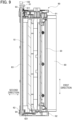
- Each pressure shaft 102 is movable in the first direction between a retracted position (illustrated in Fig. 9 ) and a protruding position (illustrated in Fig. 11 ), the protruding position being closer to the developing cartridge 1 than the retracted position is to the developing cartridge 1.
- the image-forming apparatus 100 is configured to move the pressure shaft 102 from the retracted position to the protruding position, which movement brings the pressure shaft 102 into contact with the first cam 61. Accordingly, the pressure shaft 102 pushes the separation member 60 in the direction toward the second cam 62 from the first cam 61 in the first direction.
- the resilient member 67 is compressed, thereby moving the separation member 60 in the first position relative to the casing 10 from the first position to the second position. That is, the separation member 60 moves in the first direction, relative to the drum frame 90, from the first position to the second position.
- the separation member 60 moves from the first position to the second position, the first inclined surface 611 of the first cam 61 moves in the first direction while being in contact with the first bearing part 93 of the drum cartridge 2.
- the first cam 61 moves in a direction away from the photosensitive drum 80, relative to the drum frame 90, by a reaction force applied from the first bearing part 93.
- the separation member 60 moves from the first position to the second position, the second inclined surface 621 of the second cam 62 moves in the first direction while being in contact with the second bearing part 94 of the drum cartridge 2.
- the second cam 62 moves in the direction away from the photosensitive drum 80, relative to the drum frame 90, by a reaction force applied from the second bearing part 94.
- the position of the center of gravity G of the developing cartridge 1 is subject to change according to the consumption amount of the developing agent. Specifically, as the developing agent stored in the casing 10 decreases, the position of the center of gravity G of the developing cartridge 1 moves toward the developing roller 30.
- the position of the center of gravity G of the developing cartridge 1 and the position of the shaft 63 may not be in line with each other in the second direction throughout an entire phase of the developing cartridge 1 from a non-used state to a used-up state.
- the position of the center of gravity G of the developing cartridge 1 and the position of the shaft 63 may be in line with each other in the second direction in any one of the phases from the non-used state to the used-up state.
- the first cam 61 of the separation member 60 is held by the gear cover 41.
- the one end portion of the shaft 63 in the first direction may be held by the gear cover 41.
- the second cam 62 of the separation member 60 is held by the holder cover 53.
- the other end portion of the shaft 63 in the first direction may be held by the holder cover 53.
- the separation member 60 includes the first cam 61 and the second cam 62. However, the separation member 60 may not include the second cam 62. Further, in the above-described embodiment, the drum frame 90 includes the first bearing part 93 and the second bearing part 94. However, the drum frame 90 may not include the second bearing part 94.
- the first cam 61, the second cam 62, and the shaft 63 are integrally molded with resin.
- the first cam 61, the second cam 62, and the shaft 63 may be components independent of each other.
- the shaft 63 may be made from metal such as iron.
- the four developing cartridge 1 are attachable to the single drum cartridge 2.
- the number of the developing cartridges 1 attachable to the drum cartridge 2 may be one through three, or five or more.
Landscapes
- Physics & Mathematics (AREA)
- General Physics & Mathematics (AREA)
- Engineering & Computer Science (AREA)
- Computer Vision & Pattern Recognition (AREA)
- Dry Development In Electrophotography (AREA)
- Electrophotography Configuration And Component (AREA)
Abstract
Description
- The present disclosure relates to a developing cartridge.
- Conventionally, there has been known an electrophotographic type image-forming apparatus such as a laser printer and an LED printer. Such a conventional image-forming apparatus is described in, for example,
Patent literature 1. - The image-forming apparatus described in
Patent literature 1 includes a developing cartridge and a drum cartridge. The developing cartridge includes a developing roller. The drum cartridge includes a photosensitive drum. The developing roller contacts the photosensitive drum upon attachment of the developing cartridge to the drum cartridge. - The image-forming apparatus described in
Patent literature 1 further includes a separation member. The separation member is movable relative to a casing of the developing cartridge. Once the separation member is moved in a state where the developing cartridge is attached to the drum cartridge, the separation member contacts a frame of the drum cartridge. Hence, the developing cartridge is moved relative to the drum cartridge. As a result, the developing roller can be separated from the photosensitive drum. - [PTL 1]
Japanese Patent Application Publication No. 2019-179128 - However, in the developing cartridge according to
Patent literature 1, the separation member is positioned, among outer surfaces of the casing of the developing cartridge, on a surface that is on the same side as the developing roller (the outer surface of a lid 10B in Patent literature). In this structure, it is hard to arrange the separation member in line with a center of gravity of the developing cartridge in a separating direction. Accordingly, a larger load is likely to be imparted on the separation member in order to move the developing cartridge in the separating direction. - In view of the foregoing, it is an object of the present disclosure to provide a developing cartridge capable of reducing a load that is to be imparted on the separation member during a separating operation.
- In order to solve the above-described problem, a first aspect of the disclosure provides a developing cartridge including: a casing configured store developing agent therein; a developing roller rotatable about a first axis extending in a first direction; a shaft extending along a second axis extending in the first direction; and a first cam positioned at one end portion of the shaft in the first direction, wherein a part of a peripheral surface of the developing roller on one side in a second direction is exposed to an outside of the casing and another part of the peripheral surface of the developing roller on an other side in the second direction is positioned inside the casing; the developing roller is positioned at one end portion of the casing in a third direction crossing the first direction and the second direction; the shaft is movable in the first direction relative to the casing and the developing roller; the first cam is movable in the first direction together with the shaft; and the first cam has a first inclined surface that is inclined to approach the developing roller in the second direction as extending toward the one end portion of the shaft from an other end portion of the shaft in the first direction. The developing cartridge is characterized in that the shaft and the first cam are positioned at an other end portion of the casing in the third direction.
- A second aspect of the disclosure provides the developing cartridge according to the first aspect that further includes an agitator rotatable about a third axis extending in the first direction and including an agitator shaft extending in the first direction. The developing cartridge is characterized in that the shaft and the first cam are positioned opposite the developing roller with respect to the agitator shaft in the third direction.
- A third aspect of the disclosure provides the developing cartridge according to the first or the second aspect which is characterized in that the shaft is aligned with a center of gravity of the developing cartridge in the second direction.
- A fourth aspect of the disclosure provides the developing cartridge according to any one of the first through third aspects which is characterized in that the casing has: a first outer surface positioned on the same side as the developing roller in the third direction; and a second outer surface positioned on the same side as the shaft and the first cam in the third direction.
- A fifth aspect of the disclosure provides the developing cartridge according to the fourth aspect which is characterized in that the first cam is positioned between the first outer surface and the second outer surface in the third direction.
- A sixth aspect of the disclosure provides the developing cartridge according to the fourth or fifth aspect which is characterized in that the first cam is positioned at the second outer surface.
- A seventh aspect of the disclosure provides the developing cartridge according to the sixth aspect which is characterized in that: the second outer surface has a groove extending in the first direction; and the shaft is positioned in the groove.
- According to an eighth aspect of the disclosure, the developing cartridge of the sixth or seventh aspect is characterized in that: the casing includes a rib protruding from the second outer surface; and the shaft is positioned between the second outer surface and the rib in the second direction.
- A ninth aspect of the disclosure provides the developing cartridge according to any one of the first through eighth aspects which is characterized by further including a resilient member configured to expand and compress in the first direction and positioned between the casing and the first cam in the first direction.
- A tenth aspect of the disclosure provides the developing cartridge according to any one of the first through ninth aspects which is characterized by further including a gear cover positioned at the one end portion of the casing in the first direction, and in that the first cam is held by the gear cover.
- An eleventh aspect of the disclosure provides the developing cartridge according to the tenth aspect which is characterized in that: the gear cover has a first through-hole penetrating the gear cover in the first direction; and the first cam is inserted in the first through-hole.
- A twelfth aspect of the disclosure, the developing cartridge according to any one of the first through eleventh aspects which is characterized by further including a second cam positioned at the other end portion of the shaft in the first direction and movable in the first direction together with the shaft, the second cam having a second inclined surface that is inclined to approach the developing roller in the second direction as extending toward the one end portion of the shaft from the other end portion of the shaft in the first direction, the second cam being positioned at the other end portion of the casing in the third direction.
- A thirteenth aspect of the disclosure provides the developing cartridge according to the twelfth aspect which is characterized by further including a holder cover positioned at an other end portion of the casing in the first direction, the second cam being held by the holder cover.
- A fourteenth aspect of the disclosure provides the developing cartridge according to the thirteenth aspect which is characterized in that the holder cover has a second through-hole penetrating the holder cover in the first direction, the second cam being inserted in the second through-hole.
- A fifteenth aspect of the disclosure provides the developing cartridge according to the thirteenth or fourteenth aspect which is characterized by further including: a storage medium having an electrical contact surface; and a holder holding the electrical contact surface, the holder being positioned between the casing and the holder cover in the first direction, the shaft and the first cam being positioned opposite the developing roller with respect to the holder in the third direction.
- A sixteenth aspect of the disclosure provides the developing cartridge according to any one of the first through fifteenth aspects which is characterized in that: the casing has a toner filling port; and the shaft and the first cam are positioned opposite the developing roller with respect to the toner filling port in the third direction.
- A seventeenth aspect of the disclosure provides the developing cartridge according to any one of the first through sixteenth aspects which is characterized in that the shaft and the first cam are integrally molded with resin.
- An eighteenth aspect of the disclosure provides the developing cartridge according to any one of the first through seventeenth aspects which is characterized by further including a storage medium having an electrical contact surface, the third direction crossing the electrical contact surface.
- According to the first through eighteenth aspects of the present disclosure, the shaft and the first cam are positioned opposite the developing roller in the third direction. With this structure, the shaft can be arranged closer to a position aligned with the center of gravity of the developing cartridge in the second direction. Accordingly, a load to be imparted on the shaft for moving the developing cartridge in the second direction can be reduced.
- Further, according to the third aspect of the present disclosure, the load to be imparted on the shaft for moving the developing cartridge in the second direction in a separating operation can be reduced.
- Further, according to the seventh aspect of the present disclosure, the positional displacement of the shaft can be restrained by positioning the shaft in the groove.
- Further, according to the eighth aspect of the present disclosure, the casing is made movable relative to the drum cartridge in the second direction by the pressure applied from the shaft to the rib in the second direction in the separating operation.
-
- [
Fig. 1] Fig. 1 is a schematic diagram of an image-forming apparatus. - [
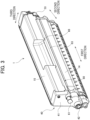
Fig. 2] Fig. 2 is a perspective view of a developing cartridge. - [
Fig. 3] Fig. 3 is another perspective view of the developing cartridge. - [
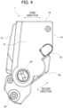
Fig. 4] Fig. 4 is a view of the developing cartridge as viewed in a first direction. - [
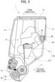
Fig. 5] Fig. 5 is a vertical cross-sectional view of the developing cartridge taken along a plane perpendicular to the first direction. - [
Fig. 6] Fig. 6 is an exploded perspective view of the developing cartridge. - [
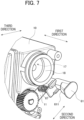
Fig. 7] Fig. 7 is a partial perspective view of the developing cartridge. - [
Fig. 8] Fig. 8 is a partial plan view of a drum cartridge. - [
Fig. 9] Fig. 9 is a transverse cross-sectional view of the drum cartridge and the developing cartridge in a state where a separating operation is not performed. - [
Fig. 10] Fig. 10 is a vertical cross-sectional view of the drum cartridge and the developing cartridge in a state where a separating operation is not performed. - [
Fig. 11] Fig. 11 is a transverse cross-sectional view of the drum cartridge and the developing cartridge in a state where a separating operation is performed. - [
Fig. 12] Fig. 12 is a vertical cross-sectional view of the drum cartridge and the developing cartridge in a state where a separating operation is performed. - Hereinafter, one embodiment of the present disclosure will be described while referring to the accompanying drawings.
- Incidentally, in the following description, a direction in which a first axis of a developing
roller 30 extends will be referred to as "first direction". Further, a direction in which, of a peripheral surface of the developingroller 30, a part exposed to an outside from acasing 10 and a part positioned inside thecasing 10 are aligned with each other will be referred to as "second direction". Further, a direction crossing the first direction and the second direction will be referred to as "third direction". - The first direction and the second direction cross each other (preferably, perpendicular to each other). The second direction and the third direction cross each other. The third direction and the first direction cross each other (preferably, perpendicular to each other).
-
Fig. 1 is a schematic view of an image-formingapparatus 100. The image-formingapparatus 100 is an electrophotographic type printer. Specifically, the image-formingapparatus 100 is a laser printer or an LED printer. As illustrated inFig. 1 , the image-formingapparatus 100 includes amain housing 101, adrum cartridge 2, and four developingcartridges 1. - The four developing
cartridges 1 are attachable to and detachable from thedrum cartridge 2. Further, thedrum cartridge 2 to which the four developingcartridges 1 are attached is attachable to and detachable from themain housing 101. - The four developing
cartridges 1 accommodate therein developing agents of four different colors (for example, yellow, magenta, cyan, and black). The developing agent is toner, for example. The image-formingapparatus 100 is configured to form an image on a surface of a printing sheet with the developing agents supplied from the developingcartridges 1. - Subsequently, a structure of the developing
cartridge 1 will be described.
Incidentally, the four developingcartridges 1 have the same structure as one another. Hence, in the following description, only one of the four developingcartridges 1 will be described.Figs. 2 and3 are perspective views of the developingcartridge 1.Fig .4 is a view of the developingcartridge 1 as viewed in the first direction.Fig. 5 is a vertical cross-sectional view of the developingcartridge 1 taken along a plane perpendicular to the first direction.Fig. 6 is an exploded perspective view of the developingcartridge 1. - As illustrated in
Figs. 2 through 6 , the developingcartridge 1 includes thecasing 10, anagitator 20, the developingroller 30, agear part 40, amemory assembly 50, and aseparation member 60. - The
casing 10 is a container that can store the developing agent therein. Thecasing 10 has afirst end surface 11 and asecond end surface 12. Thefirst end surface 11 is at one end portion of thecasing 10 in the first direction. Thesecond end surface 12 is at another end portion of thecasing 10 in the first direction. Thefirst end surface 11 and thesecond end surface 12 are positioned apart from each other in the first direction. - Further, the
casing 10 has a firstouter surface 13 and a secondouter surface 14.
The firstouter surface 13 is at one end portion of thecasing 10 in the third direction. The secondouter surface 14 is at another end portion of thecasing 10 in the third direction. The firstouter surface 13 and the secondouter surface 14 are positioned apart from each other in the third direction. A distance in the third direction between the firstouter surface 13 and the secondouter surface 14 is shorter than a distance in the first direction between thefirst end surface 11 and thesecond end surface 12. The firstouter surface 13 is positioned on the same side as the developingroller 30 descried later in the third direction. The secondouter surface 14 is positioned on the same side as theseparation member 60 described later in the third direction. - As illustrated in
Fig. 5 , astorage chamber 15 is provided in an interior of thecasing 10. The developing agent is stored in thestorage chamber 15. Further, thecasing 10 has anopening 16. Theopening 16 is positioned at one end portion of thecasing 10 in the second direction. Thestorage chamber 15 communicates with an exterior of thecasing 10 through theopening 16. - Further, as illustrated in
Fig. 6 , thecasing 10 includes atoner filling port 17 and acap 18. Thetoner filling port 17 is positioned at thefirst end surface 11 of thecasing 10. Thecap 18 is attachable to thetoner filling port 17 to close thetoner filling port 17. Thecap 18 is to be detached from thefirst end surface 11 for filling developing agent into thecasing 10, and the developing agent is filled in thestorage chamber 15 through thetoner filling port 17. - The
agitator 20 includes anagitator shaft 21 and afilm 22. Theagitator shaft 21 extends in the first direction. Thefilm 22 extends from theagitator shaft 21 toward an inner surface of thecasing 10. That is, thefilm 22 extends radially outwardly from theagitator shaft 21. A portion of theagitator shaft 21 and thefilm 22 are positioned inside thestorage chamber 15 of thecasing 10. - An agitator gear, which is included in the
gear part 40, is attached to one end portion of theagitator shaft 21 in the first direction. Specifically, the agitator gear included in thegear part 40 is fixed to the one end portion of theagitator shaft 21 in the first direction. As the agitator gear rotates, theagitator shaft 21 and thefilm 22 are caused to rotate about an axis (third axis) extending in the first direction. By the rotation of thefilm 22, the developing agent in thestorage chamber 15 is agitated. - The developing
roller 30 is a roller rotatable about an axis (first axis) extending in the first direction. The developingroller 30 is positioned at theopening 16 of thecasing 10. That is, the developingroller 30 is positioned at the one end portion of thecasing 10 in the second direction. Apart of the peripheral surface of the developingroller 30 on one side in the second direction is positioned outside of thecasing 10. A part of the peripheral surface of the developingroller 30 on an other side in the second direction is positioned inside thecasing 10. - Further, the developing
roller 30 is positioned on the same side as the firstouter surface 13 in the third direction. That is, the developingroller 30 is positioned at the one end portion of thecasing 10 in the third direction. - As illustrated in
Fig. 5 , the developingroller 30 includes a developing-roller body 31 and a developing-roller shaft 32. The developing-roller body 31 is a hollow cylindrical member extending in the first direction. The developing-roller body 31 is made of, for example, rubber having elasticity. The developing-roller shaft 32 is a solid columnar member extending throughout the developing-roller body 31 in the first direction. The developing-roller body 31 is fixed relative to the developing-roller shaft 32. The developing-roller shaft 32 is made of metal or electrically conductive resin. - A developing roller gear, which is included in the
gear part 40, is attached to one end portion of the developing-roller shaft 32 in the first direction. Specifically, the developing roller gear of thegear part 40 is fixed to the one end portion of the developing-roller shaft 32 in the first direction. As the developing roller gear rotates, the developing-roller shaft 32 and the developing-roller body 31 are caused to rotate about the axis (first axis) extending in the first direction. The developing agent stored in thecasing 10 is carried on an outer peripheral surface of the developing-roller body 31. - The
gear part 40 is positioned at thefirst end surface 11 of thecasing 10. Thegear part 40 includes agear cover 41, acoupling 42, and a plurality of gears. Thegear cover 41 is positioned at the one end portion of thecasing 10 in the first direction. Specifically, thegear cover 41 is fixed to thefirst end surface 11 of thecasing 10. The plurality of gears includes the above-described agitator gear and developing roller gear. At least a part of the plurality of gears is positioned between thefirst end surface 11 and thegear cover 41 in the first direction. - As illustrated in
Figs. 3 and4 , thecoupling 42 is exposed to the outside from thegear cover 41. Upon attachment of thedrum cartridge 2 to the image-formingapparatus 100 with the developingcartridges 1 attached to thedrum cartridge 2, a drive shaft of the image-formingapparatus 100 is connected to thecoupling 42. The rotation of the drive shaft is transmitted to theagitator 20 through thecoupling 42 and the agitator gear. Further, the rotation of the drive shaft is transmitted to the developingroller 30 through thecoupling 42 and the developing roller gear. - The
memory assembly 50 is positioned at thesecond end surface 12 of thecasing 10. Thememory assembly 50 includes amemory 51 as a storage medium, and aholder 52 holding thememory 51. Thememory 51 is an IC chip, for example. Thememory 51 has electrical contact surfaces 511. The electrical contact surfaces 511 are made of metal as an electrically conductive body. Of thememory 51, at least the electrical contact surfaces 511 are held on an outer surface of theholder 52. The electrical contact surfaces 511 extend to cross relative to the third direction. - The
memory 51 is configured to store various information about the developingcartridge 1. Specifically, thememory 51 is configured to store at least one of: a cumulative number of printed sheets using the developingroller 30; a cumulative number of rotations of the developingroller 30; and a cumulative consumption amount of the developing agent. Such information is information indicative of a service life of the developingcartridge 1. Further, thememory 51 may store information such as a production number of the developingcartridge 1, a matching model with which the developingcartridge 1 can be used, and the like. - As illustrated in
Figs. 3 through 5 , the developingcartridge 1 includes aholder cover 53. Theholder cover 53 is positioned at the other end portion of thecasing 10 in the first direction. Specifically, theholder cover 53 is attached to thesecond end surface 12 of thecasing 10. More specifically, theholder cover 53 is fixed to thesecond end surface 12 of thecasing 10. Theholder 52 is held by theholder cover 53. In the first direction, theholder 52 is positioned between thecasing 10 and theholder cover 53. - Upon attachment of the
drum cartridge 2 to themain housing 101 of the image-formingapparatus 100 with the developingcartridges 1 attached to thedrum cartridge 2, the electrical contact surfaces 511 of thememory 51 contacts an electrical contact provided in themain housing 101. Hence, a controller of the image-formingapparatus 100 can read information from thememory 51 and write information into thememory 51. - In a state where the
drum cartridge 2 having the developingcartridges 1 attached thereto is attached to the image-formingapparatus 100, the image-formingapparatus 100 can perform a separating operation with respect to each developingcartridge 1. The separating operation is an operation for moving the developingroller 30 from a contacting position where the developingroller 30 is in contact with aphotosensitive drum 80 to a separated position where the developingroller 30 is separated away from thephotosensitive drum 80. The image-formingapparatus 100 performs the separating operation to the developingcartridge 1 in a case where the developingcartridge 1 is not used. Hence, the developingroller 30 of the developingcartridge 1 that is not to be used is to be separated from thephotosensitive drum 80. - The
separation member 60 is configured to switch the developingroller 30 between the contacting position and the separated position. Theseparation member 60 is positioned at the other end portion of thecasing 10 in the third direction. Specifically, theseparation member 60 is positioned at the secondouter surface 14 of thecasing 10. That is, theseparation member 60 is positioned opposite the developingroller 30 with respect to theagitator shaft 21 in the third direction. Further, theseparation member 60 is positioned opposite the developingroller 30 with respect to theholder 52 in the third direction. Further, theseparation member 60 is positioned opposite the developingroller 30 with respect to thetoner filling port 17 in the third direction. - As illustrated in
Figs. 3 and6 , theseparation member 60 includes afirst cam 61, asecond cam 62, and ashaft 63. Thefirst cam 61, thesecond cam 62, and theshaft 63 are integrally molded with resin. - The
shaft 63 extends linearly along an axis (second axis) extending in the first direction. Theshaft 63 is positioned at the secondouter surface 14 of thecasing 10. Specifically, as illustrated inFigs. 5 and6 , the secondouter surface 14 of thecasing 10 has agroove 65 extending in the first direction. Theshaft 63 is positioned in thegroove 65. With this structure, theshaft 63 is held such that theshaft 63 is movable in the first direction relative to thecasing 10. Since theshaft 63 is positioned in thegroove 65, displacement of theshaft 63 in a direction crossing the first direction can be restrained. - As illustrated in
Fig. 5 , an outer surface of theshaft 63 includes a flat contactingsurface 631. The contactingsurface 631 extends in a direction crossing a rotational direction about the second axis. The contactingsurface 631 contacts a peripheral surface of thegroove 65. This structure can restrain theshaft 63 from rotating about the second axis relative to thecasing 10. - Further, as illustrated in
Figs. 5 and6 , thecasing 10 includes a pair ofribs 66. Eachrib 66 protrudes from the secondouter surface 14 of thecasing 10. Eachrib 66 partially covers thegroove 65. Theshaft 63 is positioned between thegroove 65 and eachrib 66 in the second direction. In this way, since theshaft 63 is positioned between the secondouter surface 14 and eachrib 66, positional displacement of theshaft 63 in the direction crossing the first direction can be further restrained. - The
first cam 61 is positioned at one end portion of theshaft 63 in the first direction. Thefirst cam 61 is positioned at thefirst end surface 11 of thecasing 10. Thefirst cam 61 has a firstinclined surface 611. The firstinclined surface 611 is positioned on a part of a peripheral surface of thefirst cam 61, the peripheral surface being centered on theshaft 63. The firstinclined surface 611 is inclined relative to the first direction. Specifically, the firstinclined surface 611 gradually separates from theshaft 63 in a radial direction thereof as extending toward the one end portion from an other end portion of theshaft 63 in the first direction. Further, the firstinclined surface 611 gradually approaches the developingroller 30 in the second direction as extending toward the one end portion from the other end portion of theshaft 63 in the first direction. - The
first cam 61 is held by thegear cover 41. Specifically, thegear cover 41 has a first through-hole 411. The first through-hole 411 penetrates thegear cover 41 in the first direction. A part of thefirst cam 61 is inserted in the first through-hole 411. Hence, thefirst cam 61 is held such that thefirst cam 61 is movable in the first direction relative to thegear cover 41. Further, thefirst cam 61 is restricted from rotating about the second axis relative to thegear cover 41. However, the firstinclined surface 611 is not inserted in the first through-hole 411 but is exposed to the outside from thegear cover 41. - As illustrated in
Fig. 4 , thefirst cam 61 is positioned between the firstouter surface 13 and the secondouter surface 14 in the third direction. That is, thefirst cam 61 does not protrude out from the secondouter surface 14 toward the other end portion of thecasing 10 in the third direction. With this structure, an outer dimension of the developingcartridge 1 can be reduced. - The
second cam 62 is positioned at the other end portion of theshaft 63 in the third direction. Thesecond cam 62 is positioned at thesecond end surface 12 of thecasing 10. Thesecond cam 62 has a secondinclined surface 621. The secondinclined surface 621 is positioned on a part of the peripheral surface of thesecond cam 62, the peripheral surface being centered on theshaft 63. The secondinclined surface 621 is inclined relative to the first direction. Specifically, the secondinclined surface 621 gradually separates from theshaft 63 in its radial direction as extending toward the one end portion from the other end portion of theshaft 63 in the first direction. Further, the secondinclined surface 621 gradually approaches the developingroller 30 in the second direction as extending toward the one end portion from the other end portion of theshaft 63 in the first direction. - The
second cam 61 is held by theholder cover 53. Specifically, theholder cover 53 has a second through-hole 531. The second through-hole 531 penetrates theholder cover 53 in the first direction. A part of thesecond cam 62 is inserted in the second through-hole 531. Hence, thesecond cam 62 is held such that thesecond cam 62 is movable in the first direction relative to theholder cover 53. Further, thesecond cam 62 is restricted from rotating about the second axis relative to theholder cover 53. However, the secondinclined surface 621 is not inserted in the second through-hole 531 but is exposed to the outside from theholder cover 53. - Similar to the
first cam 61, thesecond cam 62 is positioned between the firstouter surface 13 and the secondouter surface 14 in the third direction. That is, thesecond cam 62 does not protrude out from the secondouter surface 14 toward the other end portion of thecasing 10 in the third direction. Hence, the outer dimension of the developingcartridge 1 can be reduced. - The
separation member 60 is movable, relative to thecasing 10 and developingroller 30, between a first position and a second position in the first direction. The movement of theseparation member 60 from the first position to the second position represents a movement in a direction from thefirst cam 61 toward thesecond cam 62. -
Fig. 7 is a partial perspective view of the developingcartridge 1 from which thegear cover 41 is removed. As illustrated inFigs. 6 and7 , the developingcartridge 1 includes aresilient member 67. Theresilient member 67 is a spring capable of expanding and compressing in the first direction. Theresilient member 67 is positioned at thefirst end surface 11 of thecasing 10. Theresilient member 67 is interposed between thecasing 10 and thefirst cam 61 in the first direction. Theresilient member 67 has one end portion in the first direction that is seated on thefirst cam 61, and an other end portion in the first direction that is seated on thefirst end surface 11 of thecasing 10. - The
resilient member 67 is compressed to have a length shorter than its natural length in the first direction. Hence, theresilient member 67 urges theseparation member 60 in the first direction, from the second position toward the first position, relative to thecasing 10. Accordingly, theseparation member 60 is at the first position in a state where theseparation member 60 is not depressed by apressure shaft 102 described later. - Details of the separating operation using the
separation member 60 will be described later. - As illustrated in
Fig. 1 , thedrum cartridge 2 includes fourphotosensitive drums 80 and adrum frame 90. - The four
photosensitive drums 80 are supported by thedrum frame 90. The fourphotosensitive drums 80 are positioned on one end portion of thedrum frame 90 in the second direction. The fourphotosensitive drums 80 are arranged at intervals in the third direction. Eachphotosensitive drum 80 is rotatable about a drum axis extending in the first direction. Eachphotosensitive drum 80 has a cylindrical-shaped outer surface centered on the drum axis. An outer peripheral surface of eachphotosensitive drum 80 is covered with photosensitive material. Outer surfaces of the developingrollers 30 contact the outer surfaces of thephotosensitive drums 80 upon attachment of the developingcartridges 1 to thedrum cartridge 2. - The
drum frame 90 is a frame configured to support the four developingcartridges 1. The four developingcartridges 1 are attachable to and detachable from thedrum frame 90. -
Fig. 8 is a partial plan view of thedrum cartridge 2. As illustrated inFig. 8 , thedrum frame 90 includes afirst side frame 91 and asecond side frame 92. Thefirst side frame 91 is positioned at one end portion of thedrum frame 90 in the first direction. Thesecond side frame 92 is positioned at an other end portion of thedrum frame 90 in the first direction. Thefirst side frame 91 and thesecond side frame 92 are spaced apart from each other in the first direction. - The
photosensitive drum 80 is positioned between thefirst side frame 91 and thesecond side frame 92 in the first direction. Further, in a state where the developingcartridge 1 is attached to thedrum cartridge 2, thecasing 10 of the developingcartridge 1 is positioned between thefirst side frame 91 and thesecond side frame 92 in the first direction. - The
first side frame 91 includes first bearingparts 93. Thefirst bearing parts 93 are positioned at the one end portion of thedrum frame 90 in the first direction. Each first bearingpart 93 is a part configured to contact thefirst cam 61 of the corresponding developingcartridge 1 in the separating operation. In the present embodiment, thefirst bearing part 93 is a corner section formed in thefirst side frame 91. However, thefirst bearing part 93 may be a roller that is rotatable while being in contact with thefirst cam 61. - The
second side frame 92 includessecond bearing parts 94. Thesecond bearing parts 94 are positioned at the other end portion of thedrum frame 90 in the first direction. Eachsecond side frame 92 is a part configured to contact thesecond cam 62 of the corresponding developingcartridge 1 in the separating operation. In the present embodiment, thesecond bearing part 94 is a corner section formed in thesecond side frame 92. However, thesecond bearing part 94 may be a roller that is rotatable while being in contact with thesecond cam 62. - Next, the separating operation performed in the image-forming
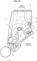
apparatus 100 will be described.Fig. 9 is a transverse cross-sectional view of thedrum cartridge 2 and the developingcartridge 1 while the separating operation is not performed.Fig. 10 is a vertical cross-sectional view of thedrum cartridge 2 and the developingcartridge 1 while the separating operation is not performed.Fig. 11 is a transverse cross-sectional view of thedrum cartridge 2 and the developingcartridge 1 while the separating operation is performed.Fig. 12 is a vertical cross-sectional view of thedrum cartridge 2 and the developingcartridge 1 while the separating operation is performed. - As illustrated in
Figs. 10 and12 , thedrum cartridge 2 includespressure mechanisms 95. The developingroller 30 is pressed by thecorresponding pressure mechanism 95 toward thephotosensitive drum 80 upon attachment of the developingcartridge 1 to thedrum cartridge 2. Hence, as illustrated inFigs. 9 and10 , the outer surface of the developingroller 30 contacts the outer surface of thephotosensitive drum 80. That is, the developingroller 30 is brought to the contacting position. - Further, as illustrated in
Figs. 9 and11 , the image-formingapparatus 100 includes thepressure shafts 102. Eachpressure shaft 102 faces thefirst cam 61 of the corresponding developingcartridge 1 in the first direction in the state where thedrum cartridge 2 having the four developingcartridges 1 attached thereto is attached to themain housing 101. - Each
pressure shaft 102 is movable in the first direction between a retracted position (illustrated inFig. 9 ) and a protruding position (illustrated inFig. 11 ), the protruding position being closer to the developingcartridge 1 than the retracted position is to the developingcartridge 1. For performing the separating operation, the image-formingapparatus 100 is configured to move thepressure shaft 102 from the retracted position to the protruding position, which movement brings thepressure shaft 102 into contact with thefirst cam 61. Accordingly, thepressure shaft 102 pushes theseparation member 60 in the direction toward thesecond cam 62 from thefirst cam 61 in the first direction. As a result, theresilient member 67 is compressed, thereby moving theseparation member 60 in the first position relative to thecasing 10 from the first position to the second position. That is, theseparation member 60 moves in the first direction, relative to thedrum frame 90, from the first position to the second position. - As the
separation member 60 moves from the first position to the second position, the firstinclined surface 611 of thefirst cam 61 moves in the first direction while being in contact with thefirst bearing part 93 of thedrum cartridge 2. At this time, thefirst cam 61 moves in a direction away from thephotosensitive drum 80, relative to thedrum frame 90, by a reaction force applied from thefirst bearing part 93. - Similarly, as the
separation member 60 moves from the first position to the second position, the secondinclined surface 621 of thesecond cam 62 moves in the first direction while being in contact with thesecond bearing part 94 of thedrum cartridge 2. At this time, thesecond cam 62 moves in the direction away from thephotosensitive drum 80, relative to thedrum frame 90, by a reaction force applied from thesecond bearing part 94. - Further, as the
first cam 61 and thesecond cam 62 move in the direction away from thephotosensitive drum 80, theshaft 63 pushes theribs 66 of thecasing 10 in the direction away from thephotosensitive drum 80 in the second direction. As such, thecasing 10 and the developingroller 30 move, together with theseparation member 60, relative to thedrum frame 90, in the direction away from thephotosensitive drum 80 in the second direction. As a result, the developingroller 30 moves from the contacting position where the developingroller 30 contacts thephotosensitive drum 80 to the separated position where the developingroller 30 is separated away from thephotosensitive drum 80. - Particularly, in the present embodiment, the
separation member 60 is not positioned at the firstouter surface 13 of thecasing 10 but is positioned at the secondouter surface 14 of thecasing 10. That is, thefirst cam 61, thesecond cam 62, and theshaft 63 are positioned opposite the developingroller 30 in the third direction. With this structure, compared to a structure where theseparation member 60 is positioned at the firstouter surface 13 of thecasing 10, theshaft 63 can be arranged closer to a position which is in line with the position of the center of gravity G of the developingcartridge 1 in the second direction. Accordingly, a load to be imparted on theshaft 63 for moving the developingcartridge 1 in the second direction can be reduced. Consequently, a pressing force of thepressure shaft 102 required for moving thefirst cam 61 in the first direction in the separating operation can be reduced. - According to the embodiment illustrated in
Figs. 10 and12 , the center of gravity G of the developingcartridge 1 and theshaft 63 are aligned in the second direction. In this case, the load to be imparted on theshaft 63 for moving the developingcartridge 1 in the second direction can be minimized. Accordingly, the pressing force of thepressure shaft 102 required for moving thefirst cam 61 in the first direction in the separating operation can be further reduced. - Incidentally, the position of the center of gravity G of the developing
cartridge 1 is subject to change according to the consumption amount of the developing agent. Specifically, as the developing agent stored in thecasing 10 decreases, the position of the center of gravity G of the developingcartridge 1 moves toward the developingroller 30. In this connection, the position of the center of gravity G of the developingcartridge 1 and the position of theshaft 63 may not be in line with each other in the second direction throughout an entire phase of the developingcartridge 1 from a non-used state to a used-up state. For example, the position of the center of gravity G of the developingcartridge 1 and the position of theshaft 63 may be in line with each other in the second direction in any one of the phases from the non-used state to the used-up state. - Incidentally, the
holder 52 is movable in the second direction relative to thecasing 10 and theholder cover 53. Hence, the electrical contact surfaces 511 can be kept in contact with the electrical contact of themain housing 101, regardless of whether the separating operation is performed or not. - While the embodiment of the present disclosure has been described above, the present disclosure is not limited to the above-described embodiment.
- In the above-described embodiment, the
first cam 61 of theseparation member 60 is held by thegear cover 41. However, the one end portion of theshaft 63 in the first direction may be held by thegear cover 41. - Further, in the above-described embodiment, the
second cam 62 of theseparation member 60 is held by theholder cover 53. However, the other end portion of theshaft 63 in the first direction may be held by theholder cover 53. - Further, in the above-described embodiment, the
separation member 60 includes thefirst cam 61 and thesecond cam 62. However, theseparation member 60 may not include thesecond cam 62. Further, in the above-described embodiment, thedrum frame 90 includes thefirst bearing part 93 and thesecond bearing part 94. However, thedrum frame 90 may not include thesecond bearing part 94. - Further, according the above-described embodiment, the
first cam 61, thesecond cam 62, and theshaft 63 are integrally molded with resin. However, thefirst cam 61, thesecond cam 62, and theshaft 63 may be components independent of each other. Further, theshaft 63 may be made from metal such as iron. - According the above-described embodiment, the four developing
cartridge 1 are attachable to thesingle drum cartridge 2. However, the number of the developingcartridges 1 attachable to thedrum cartridge 2 may be one through three, or five or more. - Further, each component appearing in the embodiment and modifications may be suitably combined as long as no technical inconsistency arises.
-
- 1: developing cartridge
- 2: drum cartridge
- 10: casing
- 13: first outer surface
- 14: second outer surface
- 20: agitator
- 30: developing roller
- 40: gear part
- 50: memory assembly
- 60: separation member
- 61: first cam
- 62: second cam
- 63: shaft
- 65: groove
- 66: rib
- 67: resilient member
- 80: photosensitive drum
- 90: drum frame
- 93: first bearing part
- 94: second bearing part
- 100: image-forming apparatus
- G: center of gravity
Claims (18)
- A developing cartridge comprising:a casing configured to store developing agent;a developing roller rotatable about a first axis extending in a first direction, a part of a peripheral surface of the developing roller on one side in a second direction being exposed to an outside of the casing and another part of the peripheral surface on an other side in the second direction being positioned inside the casing, the developing roller being positioned at one end portion of the casing in a third direction crossing the first direction and the second direction;a shaft extending along a second axis extending in the first direction, the shaft being movable in the first direction relative to the casing and the developing roller; anda first cam positioned at one end portion of the shaft in the first direction and movable in the first direction together with the shaft, the first cam having a first inclined surface that is inclined to approach the developing roller in the second direction as extending toward the one end portion of the shaft from an other end portion of the shaft in the first direction,wherein the shaft and the first cam are positioned at an other end portion of the casing in the third direction.
- The developing cartridge according to claim 1, further comprising an agitator rotatable about a third axis extending in the first direction, the agitator including an agitator shaft extending in the first direction,
wherein the shaft and the first cam are positioned opposite the developing roller with respect to the agitator shaft in the third direction. - The developing cartridge according to claim 1 or 2,
wherein the shaft is aligned with a center of gravity of the developing cartridge in the second direction. - The developing cartridge according to claim 1 or 2,
wherein the casing has:a first outer surface positioned on the same side as the developing roller in the third direction; anda second outer surface positioned on the same side as the shaft and the first cam in the third direction. - The developing cartridge according to claim 4,
wherein the first cam is positioned between the first outer surface and the second outer surface in the third direction. - The developing cartridge according to claim 4,
wherein the first cam is positioned at the second outer surface. - The developing cartridge according to claim 6,wherein the second outer surface has a groove extending in the first direction, andwherein the shaft is positioned in the groove.
- The developing cartridge according to claim 6,wherein the casing includes a rib protruding from the second outer surface, andwherein the shaft is positioned between the second outer surface and the rib in the second direction.
- The developing cartridge according to claim 1 or 2, further comprising a resilient member configured to expand and compress in the first direction and positioned between the casing and the first cam in the first direction.
- The developing cartridge according to claim 1 or 2, further comprising a gear cover positioned at one end portion of the casing in the first direction,
wherein the first cam is held by the gear cover. - The developing cartridge according to claim 10,wherein the gear cover has a first through-hole penetrating the gear cover in the first direction, andwherein the first cam is inserted in the first through-hole.
- The developing cartridge according to claim 1 or 2, further comprising a second cam positioned at the other end portion of the shaft in the first direction and movable in the first direction together with the shaft, the second cam having a second inclined surface that is inclined to approach the developing roller in the second direction as extending toward the one end portion of the shaft from the other end portion of the shaft in the first direction,
wherein the second cam is positioned at the other end portion of the casing in the third direction. - The developing cartridge according to claim 12, further comprising a holder cover positioned at an other end portion of the casing in the first direction,
wherein the second cam is held by the holder cover. - The developing cartridge according to claim 13,wherein the holder cover has a second through-hole penetrating the holder cover in the first direction, andwherein the second cam is inserted in the second through-hole.
- The developing cartridge according to claim 13, further comprising:a storage medium having an electrical contact surface; anda holder holding the electrical contact surface and positioned between the casing and the holder cover in the first direction,wherein the shaft and the first cam are positioned opposite the developing roller with respect to the holder in the third direction.
- The developing cartridge according to claim 1 or 2,wherein the casing has a toner filling port, andwherein the shaft and the first cam are positioned opposite the developing roller with respect to the toner filling port in the third direction.
- The developing cartridge according to claim 1 or 2,
wherein the shaft and the first cam are integrally molded with resin. - The developing cartridge according to claim 1 or 2, further comprising a storage medium having an electrical contact surface,
wherein the third direction is a direction crossing the electrical contact surface.
Applications Claiming Priority (2)
| Application Number | Priority Date | Filing Date | Title |
|---|---|---|---|
| JP2022104412A JP2024004677A (en) | 2022-06-29 | 2022-06-29 | developer cartridge |
| PCT/JP2023/022732 WO2024004756A1 (en) | 2022-06-29 | 2023-06-20 | Developer cartridge |
Publications (2)
| Publication Number | Publication Date |
|---|---|
| EP4550055A1 true EP4550055A1 (en) | 2025-05-07 |
| EP4550055A4 EP4550055A4 (en) | 2026-06-03 |
Family
ID=89382216
Family Applications (1)
| Application Number | Title | Priority Date | Filing Date |
|---|---|---|---|
| EP23831202.9A Pending EP4550055A4 (en) | 2022-06-29 | 2023-06-20 | DEVELOPER CARTRIDGE |
Country Status (5)
| Country | Link |
|---|---|
| US (1) | US12693614B2 (en) |
| EP (1) | EP4550055A4 (en) |
| JP (1) | JP2024004677A (en) |
| CN (1) | CN119404152A (en) |
| WO (1) | WO2024004756A1 (en) |
Family Cites Families (12)
| Publication number | Priority date | Publication date | Assignee | Title |
|---|---|---|---|---|
| JP6136650B2 (en) * | 2013-06-28 | 2017-05-31 | ブラザー工業株式会社 | cartridge |
| JP6582972B2 (en) | 2015-12-25 | 2019-10-02 | ブラザー工業株式会社 | Developer cartridge |
| JP7047541B2 (en) | 2018-03-30 | 2022-04-05 | ブラザー工業株式会社 | Develop cartridge |
| JP7006557B2 (en) * | 2018-09-28 | 2022-01-24 | ブラザー工業株式会社 | Image forming device |
| JP7215051B2 (en) * | 2018-09-28 | 2023-01-31 | ブラザー工業株式会社 | developer cartridge |
| JP7167796B2 (en) * | 2019-03-22 | 2022-11-09 | ブラザー工業株式会社 | image forming device |
| JP7331411B2 (en) * | 2019-03-28 | 2023-08-23 | ブラザー工業株式会社 | developer cartridge |
| US11454901B2 (en) * | 2020-08-10 | 2022-09-27 | Jiangxi Yibo E-Tech Co. Ltd. | Developing cartridge |
| JP7831098B2 (en) * | 2022-04-01 | 2026-03-17 | ブラザー工業株式会社 | Developing cartridge |
| JP7889252B2 (en) * | 2022-11-28 | 2026-07-14 | ブラザー工業株式会社 | Developing cartridge and image forming apparatus |
| JP2024116676A (en) * | 2023-02-16 | 2024-08-28 | ブラザー工業株式会社 | Image forming device |
| JP2024171771A (en) * | 2023-05-30 | 2024-12-12 | ブラザー工業株式会社 | Drum unit |
-
2022
- 2022-06-29 JP JP2022104412A patent/JP2024004677A/en active Pending
-
2023
- 2023-06-20 CN CN202380047725.3A patent/CN119404152A/en active Pending
- 2023-06-20 EP EP23831202.9A patent/EP4550055A4/en active Pending
- 2023-06-20 WO PCT/JP2023/022732 patent/WO2024004756A1/en not_active Ceased
-
2024
- 2024-12-17 US US18/983,693 patent/US12693614B2/en active Active
Also Published As
| Publication number | Publication date |
|---|---|
| JP2024004677A (en) | 2024-01-17 |
| US20250116954A1 (en) | 2025-04-10 |
| WO2024004756A1 (en) | 2024-01-04 |
| EP4550055A4 (en) | 2026-06-03 |
| US12693614B2 (en) | 2026-07-28 |
| CN119404152A (en) | 2025-02-07 |
Similar Documents
| Publication | Publication Date | Title |
|---|---|---|
| JP6776567B2 (en) | Image forming device | |
| JP7501736B2 (en) | Developing cartridge and image forming apparatus | |
| JP7352531B2 (en) | image forming device | |
| JP2020160224A (en) | Drum cartridge and development cartridge | |
| JP2026012935A (en) | Developer cartridge | |
| JP7552309B2 (en) | Developing cartridge | |
| EP3779601B1 (en) | Developing cartridge | |
| JP2020160223A (en) | Developing cartridge | |
| CN120202441A (en) | Developer Box | |
| JP7831098B2 (en) | Developing cartridge | |
| US20250116954A1 (en) | Developing cartridge including shaft and cam positioned on opposite side of casing from developing roller and movable in axial direction of developing roller | |
| JP7665994B2 (en) | How to assemble a developing cartridge | |
| JP2024171771A (en) | Drum unit | |
| JP2020160222A (en) | Developing cartridge | |
| EP3754430B1 (en) | Developing cartridge | |
| CN113678068B (en) | Developer Box | |
| CN223051644U (en) | Developing cartridge | |
| JP7552351B2 (en) | Developing cartridge | |
| JP7529002B2 (en) | Image forming device | |
| EP4682638A1 (en) | Developer cartridge | |
| JP2021162816A (en) | Developing cartridge | |
| CN118778385A (en) | Drum Unit | |
| EP3738000B1 (en) | Drum cartridge and developing cartridge | |
| JP2024114342A (en) | cartridge | |
| JP2026007162A (en) | Developing cartridge |
Legal Events
| Date | Code | Title | Description |
|---|---|---|---|
| STAA | Information on the status of an ep patent application or granted ep patent |
Free format text: STATUS: THE INTERNATIONAL PUBLICATION HAS BEEN MADE |
|
| PUAI | Public reference made under article 153(3) epc to a published international application that has entered the european phase |
Free format text: ORIGINAL CODE: 0009012 |
|
| STAA | Information on the status of an ep patent application or granted ep patent |
Free format text: STATUS: REQUEST FOR EXAMINATION WAS MADE |
|
| 17P | Request for examination filed |
Effective date: 20241216 |
|
| AK | Designated contracting states |
Kind code of ref document: A1 Designated state(s): AL AT BE BG CH CY CZ DE DK EE ES FI FR GB GR HR HU IE IS IT LI LT LU LV MC ME MK MT NL NO PL PT RO RS SE SI SK SM TR |
|
| P01 | Opt-out of the competence of the unified patent court (upc) registered |
Free format text: CASE NUMBER: APP_22565/2025 Effective date: 20250513 |
|
| DAV | Request for validation of the european patent (deleted) | ||
| DAX | Request for extension of the european patent (deleted) | ||
| A4 | Supplementary search report drawn up and despatched |
Effective date: 20260507 |
|
| RIC1 | Information provided on ipc code assigned before grant |
Ipc: G03G 15/08 20060101AFI20260429BHEP Ipc: G03G 21/16 20060101ALI20260429BHEP Ipc: G03G 21/18 20060101ALI20260429BHEP |