EP4550039A1 - Display device - Google Patents
Display device Download PDFInfo
- Publication number
- EP4550039A1 EP4550039A1 EP22951262.9A EP22951262A EP4550039A1 EP 4550039 A1 EP4550039 A1 EP 4550039A1 EP 22951262 A EP22951262 A EP 22951262A EP 4550039 A1 EP4550039 A1 EP 4550039A1
- Authority
- EP
- European Patent Office
- Prior art keywords
- area
- dots
- substrate
- frame
- disposed
- Prior art date
- Legal status (The legal status is an assumption and is not a legal conclusion. Google has not performed a legal analysis and makes no representation as to the accuracy of the status listed.)
- Pending
Links
Images















Classifications
-
- G—PHYSICS
- G02—OPTICS
- G02F—OPTICAL DEVICES OR ARRANGEMENTS FOR THE CONTROL OF LIGHT BY MODIFICATION OF THE OPTICAL PROPERTIES OF THE MEDIA OF THE ELEMENTS INVOLVED THEREIN; NON-LINEAR OPTICS; FREQUENCY-CHANGING OF LIGHT; OPTICAL LOGIC ELEMENTS; OPTICAL ANALOGUE/DIGITAL CONVERTERS
- G02F1/00—Devices or arrangements for the control of the intensity, colour, phase, polarisation or direction of light arriving from an independent light source, e.g. switching, gating or modulating; Non-linear optics
- G02F1/01—Devices or arrangements for the control of the intensity, colour, phase, polarisation or direction of light arriving from an independent light source, e.g. switching, gating or modulating; Non-linear optics for the control of the intensity, phase, polarisation or colour
- G02F1/13—Devices or arrangements for the control of the intensity, colour, phase, polarisation or direction of light arriving from an independent light source, e.g. switching, gating or modulating; Non-linear optics for the control of the intensity, phase, polarisation or colour based on liquid crystals, e.g. single liquid crystal display cells
- G02F1/133—Constructional arrangements; Operation of liquid crystal cells; Circuit arrangements
- G02F1/1333—Constructional arrangements; Manufacturing methods
- G02F1/1335—Structural association of cells with optical devices, e.g. polarisers or reflectors
- G02F1/1336—Illuminating devices
- G02F1/133602—Direct backlight
- G02F1/133608—Direct backlight including particular frames or supporting means
-
- G—PHYSICS
- G06—COMPUTING OR CALCULATING; COUNTING
- G06F—ELECTRIC DIGITAL DATA PROCESSING
- G06F1/00—Details not covered by groups G06F3/00 - G06F13/00 and G06F21/00
- G06F1/16—Constructional details or arrangements
- G06F1/1601—Constructional details related to the housing of computer displays, e.g. of CRT monitors, of flat displays
-
- G—PHYSICS
- G02—OPTICS
- G02F—OPTICAL DEVICES OR ARRANGEMENTS FOR THE CONTROL OF LIGHT BY MODIFICATION OF THE OPTICAL PROPERTIES OF THE MEDIA OF THE ELEMENTS INVOLVED THEREIN; NON-LINEAR OPTICS; FREQUENCY-CHANGING OF LIGHT; OPTICAL LOGIC ELEMENTS; OPTICAL ANALOGUE/DIGITAL CONVERTERS
- G02F1/00—Devices or arrangements for the control of the intensity, colour, phase, polarisation or direction of light arriving from an independent light source, e.g. switching, gating or modulating; Non-linear optics
- G02F1/01—Devices or arrangements for the control of the intensity, colour, phase, polarisation or direction of light arriving from an independent light source, e.g. switching, gating or modulating; Non-linear optics for the control of the intensity, phase, polarisation or colour
- G02F1/13—Devices or arrangements for the control of the intensity, colour, phase, polarisation or direction of light arriving from an independent light source, e.g. switching, gating or modulating; Non-linear optics for the control of the intensity, phase, polarisation or colour based on liquid crystals, e.g. single liquid crystal display cells
- G02F1/133—Constructional arrangements; Operation of liquid crystal cells; Circuit arrangements
- G02F1/1333—Constructional arrangements; Manufacturing methods
- G02F1/133308—Support structures for LCD panels, e.g. frames or bezels
- G02F1/133317—Intermediate frames, e.g. between backlight housing and front frame
-
- G—PHYSICS
- G02—OPTICS
- G02F—OPTICAL DEVICES OR ARRANGEMENTS FOR THE CONTROL OF LIGHT BY MODIFICATION OF THE OPTICAL PROPERTIES OF THE MEDIA OF THE ELEMENTS INVOLVED THEREIN; NON-LINEAR OPTICS; FREQUENCY-CHANGING OF LIGHT; OPTICAL LOGIC ELEMENTS; OPTICAL ANALOGUE/DIGITAL CONVERTERS
- G02F1/00—Devices or arrangements for the control of the intensity, colour, phase, polarisation or direction of light arriving from an independent light source, e.g. switching, gating or modulating; Non-linear optics
- G02F1/01—Devices or arrangements for the control of the intensity, colour, phase, polarisation or direction of light arriving from an independent light source, e.g. switching, gating or modulating; Non-linear optics for the control of the intensity, phase, polarisation or colour
- G02F1/13—Devices or arrangements for the control of the intensity, colour, phase, polarisation or direction of light arriving from an independent light source, e.g. switching, gating or modulating; Non-linear optics for the control of the intensity, phase, polarisation or colour based on liquid crystals, e.g. single liquid crystal display cells
- G02F1/133—Constructional arrangements; Operation of liquid crystal cells; Circuit arrangements
- G02F1/1333—Constructional arrangements; Manufacturing methods
- G02F1/133308—Support structures for LCD panels, e.g. frames or bezels
-
- G—PHYSICS
- G02—OPTICS
- G02F—OPTICAL DEVICES OR ARRANGEMENTS FOR THE CONTROL OF LIGHT BY MODIFICATION OF THE OPTICAL PROPERTIES OF THE MEDIA OF THE ELEMENTS INVOLVED THEREIN; NON-LINEAR OPTICS; FREQUENCY-CHANGING OF LIGHT; OPTICAL LOGIC ELEMENTS; OPTICAL ANALOGUE/DIGITAL CONVERTERS
- G02F1/00—Devices or arrangements for the control of the intensity, colour, phase, polarisation or direction of light arriving from an independent light source, e.g. switching, gating or modulating; Non-linear optics
- G02F1/01—Devices or arrangements for the control of the intensity, colour, phase, polarisation or direction of light arriving from an independent light source, e.g. switching, gating or modulating; Non-linear optics for the control of the intensity, phase, polarisation or colour
- G02F1/13—Devices or arrangements for the control of the intensity, colour, phase, polarisation or direction of light arriving from an independent light source, e.g. switching, gating or modulating; Non-linear optics for the control of the intensity, phase, polarisation or colour based on liquid crystals, e.g. single liquid crystal display cells
- G02F1/133—Constructional arrangements; Operation of liquid crystal cells; Circuit arrangements
- G02F1/1333—Constructional arrangements; Manufacturing methods
- G02F1/133388—Constructional arrangements; Manufacturing methods with constructional differences between the display region and the peripheral region
-
- G—PHYSICS
- G02—OPTICS
- G02F—OPTICAL DEVICES OR ARRANGEMENTS FOR THE CONTROL OF LIGHT BY MODIFICATION OF THE OPTICAL PROPERTIES OF THE MEDIA OF THE ELEMENTS INVOLVED THEREIN; NON-LINEAR OPTICS; FREQUENCY-CHANGING OF LIGHT; OPTICAL LOGIC ELEMENTS; OPTICAL ANALOGUE/DIGITAL CONVERTERS
- G02F1/00—Devices or arrangements for the control of the intensity, colour, phase, polarisation or direction of light arriving from an independent light source, e.g. switching, gating or modulating; Non-linear optics
- G02F1/01—Devices or arrangements for the control of the intensity, colour, phase, polarisation or direction of light arriving from an independent light source, e.g. switching, gating or modulating; Non-linear optics for the control of the intensity, phase, polarisation or colour
- G02F1/13—Devices or arrangements for the control of the intensity, colour, phase, polarisation or direction of light arriving from an independent light source, e.g. switching, gating or modulating; Non-linear optics for the control of the intensity, phase, polarisation or colour based on liquid crystals, e.g. single liquid crystal display cells
- G02F1/133—Constructional arrangements; Operation of liquid crystal cells; Circuit arrangements
- G02F1/1333—Constructional arrangements; Manufacturing methods
- G02F1/1335—Structural association of cells with optical devices, e.g. polarisers or reflectors
- G02F1/1336—Illuminating devices
- G02F1/133602—Direct backlight
-
- G—PHYSICS
- G02—OPTICS
- G02F—OPTICAL DEVICES OR ARRANGEMENTS FOR THE CONTROL OF LIGHT BY MODIFICATION OF THE OPTICAL PROPERTIES OF THE MEDIA OF THE ELEMENTS INVOLVED THEREIN; NON-LINEAR OPTICS; FREQUENCY-CHANGING OF LIGHT; OPTICAL LOGIC ELEMENTS; OPTICAL ANALOGUE/DIGITAL CONVERTERS
- G02F1/00—Devices or arrangements for the control of the intensity, colour, phase, polarisation or direction of light arriving from an independent light source, e.g. switching, gating or modulating; Non-linear optics
- G02F1/01—Devices or arrangements for the control of the intensity, colour, phase, polarisation or direction of light arriving from an independent light source, e.g. switching, gating or modulating; Non-linear optics for the control of the intensity, phase, polarisation or colour
- G02F1/13—Devices or arrangements for the control of the intensity, colour, phase, polarisation or direction of light arriving from an independent light source, e.g. switching, gating or modulating; Non-linear optics for the control of the intensity, phase, polarisation or colour based on liquid crystals, e.g. single liquid crystal display cells
- G02F1/133—Constructional arrangements; Operation of liquid crystal cells; Circuit arrangements
- G02F1/1333—Constructional arrangements; Manufacturing methods
- G02F1/1335—Structural association of cells with optical devices, e.g. polarisers or reflectors
- G02F1/1336—Illuminating devices
- G02F1/133602—Direct backlight
- G02F1/133603—Direct backlight with LEDs
-
- G—PHYSICS
- G02—OPTICS
- G02F—OPTICAL DEVICES OR ARRANGEMENTS FOR THE CONTROL OF LIGHT BY MODIFICATION OF THE OPTICAL PROPERTIES OF THE MEDIA OF THE ELEMENTS INVOLVED THEREIN; NON-LINEAR OPTICS; FREQUENCY-CHANGING OF LIGHT; OPTICAL LOGIC ELEMENTS; OPTICAL ANALOGUE/DIGITAL CONVERTERS
- G02F1/00—Devices or arrangements for the control of the intensity, colour, phase, polarisation or direction of light arriving from an independent light source, e.g. switching, gating or modulating; Non-linear optics
- G02F1/01—Devices or arrangements for the control of the intensity, colour, phase, polarisation or direction of light arriving from an independent light source, e.g. switching, gating or modulating; Non-linear optics for the control of the intensity, phase, polarisation or colour
- G02F1/13—Devices or arrangements for the control of the intensity, colour, phase, polarisation or direction of light arriving from an independent light source, e.g. switching, gating or modulating; Non-linear optics for the control of the intensity, phase, polarisation or colour based on liquid crystals, e.g. single liquid crystal display cells
- G02F1/133—Constructional arrangements; Operation of liquid crystal cells; Circuit arrangements
- G02F1/1333—Constructional arrangements; Manufacturing methods
- G02F1/1335—Structural association of cells with optical devices, e.g. polarisers or reflectors
- G02F1/1336—Illuminating devices
- G02F1/133602—Direct backlight
- G02F1/133605—Direct backlight including specially adapted reflectors
-
- G—PHYSICS
- G02—OPTICS
- G02F—OPTICAL DEVICES OR ARRANGEMENTS FOR THE CONTROL OF LIGHT BY MODIFICATION OF THE OPTICAL PROPERTIES OF THE MEDIA OF THE ELEMENTS INVOLVED THEREIN; NON-LINEAR OPTICS; FREQUENCY-CHANGING OF LIGHT; OPTICAL LOGIC ELEMENTS; OPTICAL ANALOGUE/DIGITAL CONVERTERS
- G02F1/00—Devices or arrangements for the control of the intensity, colour, phase, polarisation or direction of light arriving from an independent light source, e.g. switching, gating or modulating; Non-linear optics
- G02F1/01—Devices or arrangements for the control of the intensity, colour, phase, polarisation or direction of light arriving from an independent light source, e.g. switching, gating or modulating; Non-linear optics for the control of the intensity, phase, polarisation or colour
- G02F1/13—Devices or arrangements for the control of the intensity, colour, phase, polarisation or direction of light arriving from an independent light source, e.g. switching, gating or modulating; Non-linear optics for the control of the intensity, phase, polarisation or colour based on liquid crystals, e.g. single liquid crystal display cells
- G02F1/133—Constructional arrangements; Operation of liquid crystal cells; Circuit arrangements
- G02F1/1333—Constructional arrangements; Manufacturing methods
- G02F1/1335—Structural association of cells with optical devices, e.g. polarisers or reflectors
- G02F1/1336—Illuminating devices
- G02F1/133602—Direct backlight
- G02F1/133609—Direct backlight including means for improving the color mixing, e.g. white
-
- G—PHYSICS
- G02—OPTICS
- G02F—OPTICAL DEVICES OR ARRANGEMENTS FOR THE CONTROL OF LIGHT BY MODIFICATION OF THE OPTICAL PROPERTIES OF THE MEDIA OF THE ELEMENTS INVOLVED THEREIN; NON-LINEAR OPTICS; FREQUENCY-CHANGING OF LIGHT; OPTICAL LOGIC ELEMENTS; OPTICAL ANALOGUE/DIGITAL CONVERTERS
- G02F1/00—Devices or arrangements for the control of the intensity, colour, phase, polarisation or direction of light arriving from an independent light source, e.g. switching, gating or modulating; Non-linear optics
- G02F1/01—Devices or arrangements for the control of the intensity, colour, phase, polarisation or direction of light arriving from an independent light source, e.g. switching, gating or modulating; Non-linear optics for the control of the intensity, phase, polarisation or colour
- G02F1/13—Devices or arrangements for the control of the intensity, colour, phase, polarisation or direction of light arriving from an independent light source, e.g. switching, gating or modulating; Non-linear optics for the control of the intensity, phase, polarisation or colour based on liquid crystals, e.g. single liquid crystal display cells
- G02F1/133—Constructional arrangements; Operation of liquid crystal cells; Circuit arrangements
- G02F1/1333—Constructional arrangements; Manufacturing methods
- G02F1/1335—Structural association of cells with optical devices, e.g. polarisers or reflectors
- G02F1/1336—Illuminating devices
- G02F1/133602—Direct backlight
- G02F1/133611—Direct backlight including means for improving the brightness uniformity
Definitions
- the following description relates to a display device.
- LCD liquid crystal display
- OLED organic light emitting diodes
- Micro LED a display device
- the liquid crystal panel of the LCD includes a liquid crystal layer, and a TFT substrate and a color filter substrate that are opposite each other with the liquid crystal layer interposed therebetween, and may display an image by using light provided by a backlight unit.
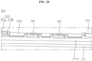
- a display device including: a display panel; a frame disposed at a rear of the display panel; a substrate disposed on the frame and having a light source that provides light; an inner frame coupled to the frame and supporting the display panel; and an optical layer disposed between the display panel and the inner frame, the optical layer placed on the inner frame, wherein the inner frame includes: a support part on which the optical layer is placed; and the sub-support part disposed between the optical layer and the frame, the sub-support part formed on the inner frame, wherein the sub-support part includes: a lower surface disposed adjacent to the substrate; an inclined surface disposed adjacent to a lower surface of the optical layer, the inclined surface reflecting the light, provided by the light source, to the optical layer; and a side surface connecting the lower surface and the inclined surface, the side surface reflecting the light provided by the light source.
- the display device according to the present disclosure has the following effects.
- a display device having a coupling structure capable of accommodating thermal expansion and/or contraction of a backlight unit may be provided.
- a display device having a firm coupling structure while reducing optical depth may be provided.
- a display device capable of improving luminance and optical uniformity of a backlight unit may be provided.
- a coupling structure of a display device capable of improving luminance and optical uniformity may be provided.
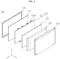
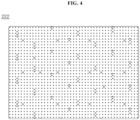
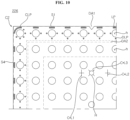
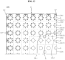
- FIGS. 1 to 36 are diagrams illustrating examples of a display device according to embodiments of the present disclosure.
- LCD liquid crystal display
- a display device may include a first long side LS1, a second long side LS2 opposite to the first long side LS1, a first short side SS1 adjacent to one end of each of the first long side LS1 and the second long side LS2, and a second short side SS2 opposite to the first short side SS1.
- an area of the first short side SS1 may be referred to as a first side area
- an area of the second short side SS2 may be referred to as a second side area opposite to the first side area
- an area of the first long side LS1 may be referred to as a third side area adjacent to the first side area and the second side area and disposed between the first side area and the second side area
- an area of the second long side LS2 may be referred to as a fourth side area adjacent to the first side area and the second side area, disposed between the first side area and the second side area, and opposite to the third side area.
- first and second long sides LS1 and LS2 are longer than the first and second short sides SS1 and SS2, but it is also possible that the lengths of the first and second long sides LS1 and LS2 may be approximately equal to the lengths of the first and second short sides SS1 and SS2.
- a first direction DR1 may be a direction parallel to the long sides LS1 and LS2 of the display device 100
- a second direction DR2 may be a direction parallel to the short sides SS1 and SS2 of the display device 100.
- a third direction DR3 may be a direction perpendicular to the first direction DR1 and/or the second direction DR2.
- the first direction DR1 and the second direction DR2 may be collectively referred to as a horizontal direction. Further, the third direction DR3 may be referred to as a vertical direction.
- a side or a surface, on which the display device displays an image may be referred to as a forward direction or a front side or a front surface.
- a side or a surface, at which the image cannot be observed may be referred to as a rearward direction or a rear side or a rear surface.
- the first long side LS1 When the display device is viewed from the forward direction or the front side or the front surface, the first long side LS1 may be referred to as an upper side or an upper surface. Likewise, the second long side LS2 may be referred to as a lower side or a lower surface. Likewise, the first short side SS1 may be referred to as a right side or a right surface, and the second short side SS2 may be referred to as a left side or a left surface.
- the first long side LS1, the second long side LS2, the first short side SS1, and the second short side SS2 may be referred to as edges of the display device. Further, positions where the first long side LS1, the second long side LS2, the first short side SS1, and the second short side SS2 meet each other may be referred to as corners.
- a position where the first long side LS1 and the first short side SS1 meet may be referred to as a first corner C1
- a position where the first long side LS1 and the second short side SS2 meet may be referred to as a second corner C2
- a position where the second short side SS2 and the second long side LS2 each other may be referred to as a third corner C3
- a position where the second long side LS2 and the first short side SS1 meet may be referred to as a fourth corner C4.
- a direction from the first short side SS1 to the second short side SS2 or a direction from the second short side SS2 to the first short side SS1 may be referred to as a left-right direction LR.
- a direction from the first long side LS1 to the second long side LS2 or a direction from the second long side LS2 to the first long side LS1 may be referred to as an up-down direction UD.
- a front cover 105 may cover at least a portion of the front and side surfaces of a display panel 110.
- the front cover 105 may be divided into a front cover located on the front surface of the display panel 110, and a side cover located on the side surface of the display panel 110. Either one of the front cover or the side cover may be omitted.
- the display panel 110 may be provided on the front surface of the display device 100 and may display an image.
- the display panel 110 may display an image in such a manner that a plurality of pixels output red, green or blue (RGB) for each pixel according to the timing.
- the display panel 110 may be divided into an active area, on which an image is displayed, and a de-active area on which an image is not displayed.
- the display panel 110 may include a front substrate and a rear substrate which are disposed opposite each other with a liquid crystal layer interposed therebetween.
- the front substrate may include a plurality of pixels composed of red (R), green (G), and blue (B) subpixels.
- the front substrate may emit light corresponding to red, green, or blue color in response to a control signal.
- the backlight unit 120 may be disposed at the rear of the display panel 110.
- the backlight unit 120 may include light sources.
- the backlight unit 120 may be coupled to a frame 130 in front of the frame 130.
- the frame 130 may be referred to as a rear frame 130 or a main frame 130.
- the backlight unit 120 may be driven by a full driving scheme or a partial driving scheme, such as local dimming, impulsive driving, or the like.
- the back light unit 120 may include an optical sheet 125 and an optical layer 123.
- the optical layer 123 may be referred to as an optical module 123 or an optical unit 123.
- the optical sheet 125 may allow light from the light source to be evenly transmitted to the display panel 110.
- the optical sheet 125 may be composed of a plurality of layers.
- the optical sheet 125 may include a prism sheet, a diffusion sheet, and the like.
- the optical sheet 125 may include a coupling part 125d.
- the coupling part 125d may be coupled to the front cover 105, the frame 130, and/or a back cover 150.
- the coupling part 125d may be fastened to a structure formed on or coupled to the front cover 105, the frame 130, and/or the back cover 150.
- the frame 130 may serve to support components of the display device 100.
- components such as the backlight unit 120 and the like, may be coupled to the frame 130.
- the frame 130 may be made of a metal material, such as an aluminum alloy and the like.
- the back cover 150 may be disposed on the rear surface or rear side of the display device 100.
- the back cover 150 may be coupled to the frame 130 and/or the front cover 105.
- the back cover 150 may be an injection-molded product made of a resion material.
- a substrate 122 may be formed in the shape of a plurality of straps which extend in a first direction and are spaced apart from each other in a second direction intersecting the first direction.
- At least one optical assembly 124 may be mounted on the substrate 122.
- An electrode pattern for connecting the optical assembly 124 to an adapter may be formed on the substrate 122.
- a carbon nanotube electrode pattern for connecting the optical assembly 124 to an adapter may be formed on the substrate 122.
- the substrate 122 may be made of at least one of polyethylene terephthalate (PET), glass, polycarbonate (PC), and silicon.
- the substrate 122 may be a printed circuit board (PCB) on which the at least one optical assembly 124 is mounted.
- PCB printed circuit board
- the optical assemblies 124 may be mounted on the substrate 122 at predetermined intervals in the first direction.
- a diameter of the optical assembly 124 may be greater than a width of the substrate 122. That is, the diameter may be greater than the length of the substrate 122 in the second direction.
- the optical assembly 124 may be a light emitting diode (LED) chip or an LED package including at least one LED chip.
- LED light emitting diode
- the optical assembly 124 may include a light source.
- the light source may be configured as a white LED or a colored LED emitting at least one color among colors such as red, blue, green, and the like.
- the colored LED may be a blue LED.
- the light source may be a mini LED.
- a reflective sheet 126 may be disposed on the front surface of the substrate 122.
- the reflective sheet 126 may be positioned on an area of the substrate 122, excluding the area where the optical assembly 124 is formed.
- the reflective sheet 126 may have a plurality of holes 235.
- the reflective sheet 126 may reflect light, emitted from the optical assembly 124, toward the front side. In addition, the reflective sheet 126 may recycle the light emitted from the optical assembly 124.
- Resin may be deposited or coated on the optical assembly 124 and/or the reflective sheet 126.
- the resin may serve to diffuse light emitted from the optical assembly 124.
- An optical layer 129 may include a phosphor.
- the optical layer 129 may be formed as a plate or a thin sheet.
- the optical layer 129 may include a red-based phosphor and/or a green-based phosphor.
- the optical layer 128 may change the wavelength or color of light provided by the optical assembly 124. For example, when the optical assembly 124 provides blue-based light, the optical layer 129 may change the blue-based light to white light.
- the optical layer 129 may be referred to as a quantum dot (QD) layer or QD sheet.
- QD quantum dot
- the optical sheet 125 may be disposed at the front of the optical layer 129.
- the rear surface of the optical sheet 125 may be in close contact with the optical layer 129, and the front surface of the optical sheet 125 may be in close contact with or adjacent to the rear surface of the display panel 110.
- the optical sheet 125 may include at least one or more sheets. More specifically, the optical sheet 125 may include one or more prism sheets and/or one or more diffusion sheets. The plurality of sheets included in the optical sheet 125 may be bonded or closely adhered to each other.
- the optical sheet 125 may be composed of a plurality of sheets having different functions.
- the optical sheet may include first to third optical sheets 125a to 125c.
- a first optical sheet 125a may be a diffusion sheet
- second and third optical sheets 125b and 125c may be prism sheets.
- the number and/or position of the diffusion sheet 125a and the prism sheets 125b and 125c may vary.
- the diffusion sheet 125a may prevent light, emitted from the optical layer 129, from being partially concentrated, thereby making light distribution uniform.
- the prism sheets 125b and 125c may collect light emitted from the diffusion sheet 125a and provide the collected light to the display panel 110.
- the coupling part 125d may be formed on a long side of the optical sheet 125.
- the coupling part 125d formed on the first long side may be asymmetric to the coupling part 125d formed on the second long side.
- the position and/or number of the coupling part 125d formed on the first long side and the coupling part 125d formed on the second long side may be different from each other.
- a substrate 222 may be a plate.
- the substrate 222 may have a white front surface.
- a white or reflective material may be applied to the front surface of the substrate 222.
- An optical assembly 224 may be mounted on the substrate 222.
- the optical assembly 224 may include a light source and a mini-lens.
- the light source may be a mini LED providing blue light.
- a plurality of light sources may be mounted on the substrate 222. The plurality of light sources may be arranged in a plurality of rows and a plurality of columns.
- An integrated device 2223 and a capacitor 2224 may be disposed around the light source 224.
- the integrated device 2223 may be an IC chip 2223.
- a plurality of capacitors 2224 may be opposite the integrated device 2223.
- the integrated device 2223 may control power supplied to the plurality of light sources 224 provided in a predetermined number.
- a supporter 2221 may be mounted on the substrate 222.
- the supporter 2221 may maintain a constant distance between the substrate 222 and the aforementioned optical layer 129.
- the supporter 2221 may have a generally conical shape.
- the supporter 2221 may be formed by double injection and may be bonded to the substrate 222.
- the supporter 2221 may be disposed between the optical assemblies 224 and may be fixed onto the substrate 222.
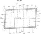
- the plurality of substrates 222 may include a first substrate 222a, a second substrate 222b, a third substrate 222c, a fourth substrate 222d, a fifth substrate 222e, a sixth substrate 222f, a seventh substrate 222g, an eighth substrate 222h, a ninth substrate 222i, and a tenth substrate 222j.
- the first substrate 222a may be positioned in contact with the first long side LS1 and the first short side SS1, and may form the first corner C1.
- the second substrate 222b may be positioned in contact with the first short side SS1 and the second long side LS2, and may form the fourth corner C4.
- the second substrate 222b may be vertically next to the first substrate 222a.
- the ninth substrate 222i may be positioned in contact with the first long side LS1 and the second short side SS2, and may form the second corner C2.
- the tenth substrate 222j may be positioned in contact with the second short side SS2 and the second long side LS2 and, and may form the third corner C3.
- the tenth substrate 222j may be vertically next to the ninth substrate 222i.
- the fifth substrate 222e may be in contact with the first long side LS1 and may be disposed between the first substrate 222a and the ninth substrate 222i.
- the sixth substrate 222f may be in contact with the second long side LS2 and may be disposed between the second substrate 222b and the tenth substrate 222j.
- the sixth substrate 222f may be vertically next to the fifth substrate 222e.
- the third substrate 222c may be in contact with the first long side LS1 and may be disposed between the first substrate 222a and the fifth substrate 222e.
- the fourth substrate 222d may be in contact with the second long side LS2 and may be disposed between the second substrate 222b and the sixth substrate 222f.
- the fourth substrate 222d may be vertically next to the third substrate 222c.
- the seventh substrate 222g may be in contact with the first long side LS1 and may be disposed between the fifth substrate 222e and the ninth substrate 222i.
- the eighth substrate 222h may be in contact with the second long side LS2 and may be disposed between the sixth substrate 222f and the tenth substrate 222j.
- the eighth substrate 222h may be vertically next to the seventh substrate 222g.
- the reflective sheet 226 may cover the substrate 222. There may be a plurality of reflective sheets 226. The plurality of reflective sheets 226 may cover a plurality of substrates 222. The plurality of reflective sheets 226 may include a first reflective sheet 226a, a second reflective sheet 226b, a third reflective sheet 226c, a fourth reflective sheet 226d, a fifth reflective sheet 226e, and a sixth reflective sheet 226f.
- the first reflective sheet 226a may cover the first substrate 222a.
- the first reflective sheet 226a may overlap the second substate 222b, the third substrate 222c, and the fourth substrate 222d.
- the second reflective sheet 226b may cover at least a portion or most of the second substrate 222b, and may overlap the fourth substrate 222d.
- the fifth reflective sheet 226e may cover at least a portion or most of the ninth substrate 222i, and may overlap the seventh substate 222g.
- the sixth reflective sheet 226f may cover the tenth substrate 222j.
- the sixth reflective sheet 226f may overlap the seventh substrate 222g, the eighth substrate 222h, and the ninth substrate 222i.
- An area DA or a dot area DA or a pattern area DA may be formed along the first long side LS1, the second long side LS2, the first short side SS1, and/or the second short side SS2.
- the reflective sheet 226 may include a plurality of holes h and a plurality of cut-lines CL.
- the plurality of holes h may be formed corresponding to the light sources 224 and the optical assemblies 224.
- An area of the hole h may be greater than a transverse cross-sectional area of the optical assembly 224.
- the reflective sheet 26 may have an accommodation hole H.
- a cut-line CL3 may be formed around the accommodation hole H.
- the cut-line CL3 may be formed in a radial direction of the accommodation hole H.
- the cut-line CL3 may have a + or cross shape.
- the accommodation hole H may be referred to as a cut-line hole H.
- the integrated device 2223 may be disposed in the accommodation hole H.
- An area of the accommodation hole H may be greater than a cross-sectional area of the integrated device 2223.
- the accommodation hole H may have a circular shape, and the integrated device 2223 may have a rectangular shape.
- a portion of the integrated device 2223 may overlap the accommodation hole H, and the cut-line CL around the accommodation hole H may be opened.
- the reflective sheet 226 may have a cut-line CL.
- the cut-line may have a + or cross shape.
- Cut-lines CL1 and CL2 may be formed between the holes h, and may be disposed adjacent to the accommodation hole H.
- a first cut-line CL1 may be disposed between the holes h and may be disposed adjacent to the accommodation hole H.
- a second cut-line CL2 may be opposite the first cut-line CL1 with respect to the accommodation hole H.
- the accommodation hole H may be disposed between the first cut-line CL1 and the second cut-line CL2.
- the capacitors 2224 adjacent to the integrated device 2223 may be positioned below the cut-lines CL1 and CL2, and the cut-lines CL1 and CL2 may be opened.
- the reflective sheet 26 may include a first area DA1 and a second area DA2.
- the first area DA1 may be referred to as a first dot area DA1 or a first pattern area DA1
- the second area DA2 may be referred to as a second dot area DA2 or a second pattern area DA2.
- the first area DA1 may be elongated along the first side S1 and/or the fourth side S4.
- a first plurality of holes h may be sequentially formed in the first area DA1 at regular intervals.
- the first area DA1 may be in contact with the first side S1 and/or the fourth side S4.
- the description of the first side S1 and/or the fourth side S4 may be applied to other sides S2 and S3.
- the second area DA2 may be elongated along the first side S1 and/or the fourth side S4.
- a second plurality of holes h may be sequentially formed in the second area DA2 at regular intervals.
- the second area DA2 may be in contact with or adjacent to the first area DA1.
- a distance from the first side S1 and/or the second side S2 to the second area DA2 may be greater than a distance from the first side S1 and/or the fourth side S4 to the first area DA1.
- the first area DA1 may be positioned between the second area DA2 and the first side S1 and/or the fourth side S4.
- the light pattern LP, CLP may include a phosphor.
- the light pattern LP, CLP may include a red-based phosphor and/or a green-based phosphor.
- the light pattern LP, CLP may include a yellow-based phosphor.
- the light pattern LP, CLP may have a yellow-based color, when viewed with the naked eye.
- the light pattern LP, CLP may convert blue-based light, provided by the light source 224 (see FIG. 5 ) or the optical assembly 224, into white light.
- the light pattern LP, CLP may have black or gray-based color, when viewed with the naked eye.
- the light pattern LP, CLP may absorb light provided by the light source 224 (see FIG. 5 ) or the optical assembly 224.
- the light pattern LP, CLP may be formed in the first area DA1.
- the light pattern LP, CLP may be formed between the first plurality of holes h and the first side S1 and/or the fourth side S4.
- the light pattern LP, CLP may include a plurality of segments LP and CLP.
- the plurality of segments LP and CLP may be an elongated line.
- Each of the plurality of lines LP may be positioned corresponding to each of the plurality of holes h.
- the length of the line LP may correspond to the diameter of the hole h.
- the length of the line LP may be smaller than the diameter of the hole h.
- the length of the line LP may be greater than the diameter of the hole h.
- a corner line CLP may extend while being curved and may have a fan shape or a semi-circular shape.
- the corner line CLP may be a quarter circle.
- the corner line CLP may be positioned between a hole h, disposed closest to the second corner C2, and the second corner C2.
- the description of the second corner C2 may also be applied to other corners C1, C3, and C4.
- the reflective sheet 226 may include a first area DA1 and a second area DA2.
- the first area DA1 may be referred to as a first dot area DA1 or a first pattern area DA1
- the second area DA2 may be referred to as a second dot area DA2 or a second pattern area DA2.
- the first area DA1 may be elongated along the first side S1 and/or the fourth side S4.
- a first plurality of holes h may be sequentially formed in the first area DA1 at regular intervals.
- the first area DA1 may be in contact with the first side S1 and/or the fourth side S4.
- the description of the first side S1 and/or the fourth side S4 may be applied to other sides S2 and S3.
- the second area DA2 may be elongated along the first side S1 and/or the fourth side S4.
- a second plurality of holes h may be sequentially formed in the second area DA2 at regular intervals.
- the second area DA2 may be in contact with or adjacent to the first area DA1.
- a distance from the first side S1 and/or the fourth side S4 to the second area DA2 may be greater than a distance from the first side S1 and/or the fourth side S4 to the first area DA1.
- the first area DA1 may be positioned between the second area DA2 and the first side S1 and/or the fourth side S4.
- the light pattern LP, CLP, DLP may include a phosphor.
- the light pattern LP, CLP, DLP may include a red-based phosphor and a green-based phosphor.
- the light pattern LP, CLP, DLP may include a yellow-based phosphor.
- the light pattern LP, CLP, DLP may have a yellow-based color, when viewed with the naked eye.
- the light pattern LP, CLP, DLP may convert blue-based light, provided by the light source 224 (see FIG. 5 ) or the optical assembly 224, into white light.
- the light pattern LP, CLP, DLP may have black or gray-based color, when viewed with the naked eye.
- the light pattern LP, CLP, DLP may absorb light provided by the light source 224 (see FIG. 5 ) or the optical assembly 224.
- the light pattern LP, CLP, DLP may be formed in the first area DA1.
- the light pattern LP, CLP, DLP may be formed between the first plurality of holes h and the first side S1 and/or the fourth side S4.
- the light pattern LP, CLP, DLP may include a plurality of segments LP.
- the plurality of segments LP may be an elongated line.
- Each of the plurality of lines LP may be positioned corresponding to each of the plurality of holes h.
- the length of the line LP may correspond to the diameter of the hole h.
- the length of the line LP may be smaller than the diameter of the hole h.
- the length of the line LP may be greater than the diameter of the hole h.
- the light pattern DLP may include dots DLP.
- the dots DLP may be disposed around the hole h.
- the dots DLP may be three in number.
- the line LP and the dot DLP may be disposed to surround the hole h. Two dots DLP may be positioned opposite each other with respect to the hole h, and one dot DLP may be positioned opposite the line LP with respect to the hole h.
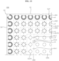
- the reflective sheet 226 may include a first area DA1, a second area DA2, a third area DA3, a fourth area DA4, and a central area CDA.
- the area DA may be referred to as a dot area DA.
- the first area DA1 may be elongated along the first side S1 and/or the fourth side S4.
- a first plurality of holes h may be sequentially formed in the first area DA1 at regular intervals.
- the first area DA1 may be in contact with the first side S1 and/or the fourth side S4.
- the description of the first side S1 and/or the fourth side S4 may be applied to other sides S2 and S3.
- the second area DA2 may be elongated along the first side S1 and/or the fourth side S4.
- a second plurality of holes h may be sequentially formed in the second area DA2 at regular intervals.
- the second area DA2 may be in contact with or next to the first area DA1.
- a distance from the first side S1 and/or the fourth side S4 to the second area DA2 may be greater than a distance from the first side S1 and/or the fourth side S4 to the first area DA1.
- the first area DA1 may be positioned between the second area DA2 and the first side S1 and/or the fourth side S4.
- the third area DA3 may be elongated along the first side S1 and/or the fourth side S4.
- a third plurality of holes h may be sequentially formed in the third area DA3 at regular intervals.
- the third area DA3 may be in contact with or next to the second area DA2.
- a distance from the first side S1 and/or the fourth side S4 to the third area DA3 may be greater than a distance from the first side S1 and/or the fourth side S4 to the second area DA2.
- the second area DA2 may be positioned between the third area DA3 and the first area DA1.
- the fourth area DA4 may be elongated along the first side S1.
- a fourth plurality of holes h may be sequentially formed in the fourth area DA4 at regular intervals.
- the fourth area DA4 may be in contact with or next to the third area DA3.
- a distance from the first side S1 and/or the fourth side S4 to the fourth area DA4 may be greater than a distance from the first side S1 and/or the fourth side S4 to the third area DA3.
- the third area DA3 may be positioned between the fourth area DA4 and the second area DA2.
- the central area CDA may be an area of the reflective sheet 226 excluding the first area DA1, the second area DA2, the third area DA3, and the fourth area DA4.
- the light pattern DLP may include a phosphor.
- the light pattern DLP may include a red-based phosphor and a green-based phosphor.
- the light pattern DLP may include a yellow-based phosphor.
- the light pattern DLP may have a yellow-based color, when viewed with the naked eye.
- the light pattern DLP may convert blue-based light, provided by the light source 224 (see FIG. 5 ) or the optical assembly 224, into white light.
- the light pattern DLP may have black or gray-based color, when viewed with the naked eye.
- the light pattern DLP may absorb light provided by the light source 224 (see FIG. 5 ) or the optical assembly 224.
- the light pattern DLP may include dots DLP.
- the dots DLP may be disposed around the hole h.
- the dots DLP may be disposed to surround the hole h.
- First dots DLP1 may be disposed around at least one hole h among the first plurality of holes h.
- the first dots DLP1 may be eight in number, and the eight first dots DLP1 may be sequentially arranged around the hole h at regular intervals.
- Second dots DLP2 may be disposed around at least one hole h among the second plurality of holes h.
- the second dots DLP2 may be eight in number, and the eight second dots DLP1 may be sequentially arranged around the hole h at regular intervals.
- Third dots DLP3 may be disposed around at least one hole h among the third plurality of holes h.
- the third dots DLP3 may be eight in number, and the eight third dots DLP1 may be sequentially arranged around the hole h at regular intervals.
- Fourth dots DLP4 may be disposed around at least one hole h among the fourth plurality of holes h.
- the fourth dots DLP4 may be three or four in number, and the four fourth dots DLP4 may be sequentially arranged around the hole h at regular intervals.
- the dots DLP4 around the hole h that is adjacent to the cut-line CL1 may be three in number.
- the dots DLP4 may be excluded from an area adjacent to the cut-line CL1 around the hole h.
- the size of the first dot DLP1 may be greater than the size of the second dot DLP2.
- the size of the second dot DLP2 may be greater than the size of the third dot DLP3.
- the size of the third dot DLP3 may be greater than the size of the fourth dot DLP4.
- the first dot DLP1, the second dot DLP2, the third dot DLP3, and the fourth dot DLP4 may have the same size. In the case where the dots DLP have the same size, the number of the dots DLP may increase.
- the description of the second corner C2 may be applied to other corners C1, C3, and C4.
- the reflective sheet 226 may include a first area DA1, a second area DA2, a third area DA3, a fourth area DA4, and a central area CDA.
- the area DA may be referred to as a dot area DA or a pattern area DA.
- the first area DA1 may be elongated along the first side S1 and/or the fourth side S4.
- a first plurality of holes h may be sequentially formed in the first area DA1 at regular intervals.
- the first area DA1 may be in contact with the first side S1 and/or the fourth side S4.
- the description of the first side S1 and/or the fourth side S4 may be applied to other sides S2 and S3.
- the second area DA2 may be elongated along the first side S1 and/or the fourth side S4.
- a second plurality of holes h may be sequentially formed in the second area DA2 at regular intervals.
- the second area DA2 may be in contact with or next to the first area DA1.
- a distance from the first side S1 and/or the fourth side S4 to the second area DA2 may be greater than a distance from the first side S1 and/or the fourth side S4 to the first area DA1.
- the first area DA1 may be positioned between the second area DA2 and the first side S1 and/or the fourth side S4.
- the third area DA3 may be elongated along the first side S1 and/or the fourth side S4.
- a third plurality of holes h may be sequentially formed in the third area DA3 at regular intervals.
- the third area DA3 may be in contact with or next to the second area DA2.
- a distance from the first side S1 and/or the fourth side S4 to the third area DA3 may be greater than a distance from the first side S1 and/or the fourth side S4 to the second area DA2.
- the second area DA2 may be positioned between the third area DA3 and the first area DA1.
- the fourth area DA4 may be elongated along the first side S1 and/or the fourth side S4.
- a fourth plurality of holes h may be sequentially formed in the fourth area DA4 at regular intervals.
- the fourth area DA4 may be in contact with or next to the third area DA3.
- a distance from the first side S1 and/or the fourth side S4 to the fourth area DA4 may be greater than a distance from the first side S1 and/or the fourth side S4 to the third area DA3.
- the third area DA3 may be positioned between the fourth area DA4 and the second area DA2.
- the light pattern DLP, LP may include a phosphor.
- the light pattern DLP, LP may include a red-based phosphor and a green-based phosphor.
- the light pattern DLP, LP may include a yellow-based phosphor.
- the light pattern DLP, LP may have a yellow-based color, when viewed with the naked eye.
- the light pattern DLP, LP may convert blue-based light, provided by the light source 224 (see FIG. 5 ) or the optical assembly 224, into white light.
- the light pattern DLP, LP may have black or gray-based color, when viewed with the naked eye.
- the light pattern DLP, LP may absorb light provided by the light source 224 (see FIG. 5 ) or the optical assembly 224.
- the light pattern DLP may include dots DLP.
- the dots DLP may be disposed around the hole h.
- the dots DLP may be disposed to surround the hole h.
- First dots DLP1 may be disposed around at least one hole h among the first plurality of holes h.
- the first dots DLP1 may be eight in number, and the eight first dots DLP1 may be sequentially arranged around the hole h at regular intervals.
- Second dots DLP2 may be disposed around at least one hole h among the second plurality of holes h.
- the second dots DLP2 may be eight in number, and the eight second dots DLP2 may be sequentially arranged around the hole h at regular intervals.
- Third dots DLP3 may be disposed around at least one hole h among the third plurality of holes h.
- the third dots DLP3 may be eight in number, and the eight third dots DLP3 may be sequentially arranged around the hole h at regular intervals.
- Fourth dots DLP4 may be disposed around at least one hole h among the fourth plurality of holes h.
- the fourth dots DLP4 may be three or four in number, and the four fourth dots DLP4 may be sequentially arranged around the hole h at regular intervals.
- the dots DLP4 around the hole h that is adjacent to the cut-line CL1 may be three in number.
- the dots DLP4 may be excluded from an area adjacent to the cut-line CL1 around the hole h.
- the size of the first dot DLP1 may be greater than the size of the second dot DLP2.
- the size of the second dot DLP2 may be greater than the size of the third dot DLP3.
- the size of the third dot DLP3 may be greater than the size of the fourth dot DLP4.
- the first dot DLP1, the second dot DLP2, the third dot DLP3, and the fourth dot DLP4 may have the same size. In the case where the dots DLP have the same size, the number of the dots DLP may increase.
- the light pattern LP may include a plurality of segments LP.
- the plurality of segments LP may be an elongated line.
- Each of the plurality of lines LP may be positioned corresponding to each of the plurality of holes h.
- the plurality of lines LP may be disposed between the first plurality of holes h and the first side S1 and/or the fourth side S4.
- the plurality of lines LP may be disposed between the first dots DA1 and the first side S1 and/or the fourth side S4.
- the length of the line LP may correspond to the diameter of the hole h. In another example, the length of the line LP may be smaller than the diameter of the hole h. In another example, the length of the line LP may be greater than the diameter of the hole h.
- the description of the second corner C2 may be applied to other corners C1, C3, and C4.
- the reflective sheet 226 may include a first area DA1, a second area DA2, a third area DA3, a fourth area DA4, and a central area CDA.
- the area DA may be referred to as a dot area DA or a pattern area DA.
- the first area DA1 may be elongated along the first side S1 and/or the fourth side S4.
- a first plurality of holes h may be sequentially formed in the first area DA1 at regular intervals.
- the first area DA1 may be in contact with the first side S1 and/or the fourth side S4.
- the description of the first side S1 and/or the fourth side S4 may be applied to other sides S2 and S3.
- the second area DA2 may be elongated along the first side S1 and/or the fourth side S4.
- a second plurality of holes h may be sequentially formed in the second area DA2 at regular intervals.
- the second area DA2 may be in contact with or next to the first area DA1.
- a distance from the first side S1 and/or the fourth side S4 to the second area DA2 may be greater than a distance from the first side S1 and/or the fourth side S4 to the first area DA1.
- the first area DA1 may be positioned between the second area DA2 and the first side S1 and/or the fourth side S4.
- the third area DA3 may be elongated along the first side S1 and/or the fourth side S4.
- a third plurality of holes h may be sequentially formed in the third area DA3 at regular intervals.
- the third area DA3 may be in contact with or next to the second area DA2.
- a distance from the first side S1 and/or the fourth side S4 to the third area DA3 may be greater than a distance from the first side S1 and/or the fourth side S4 to the second area DA2.
- the second area DA2 may be positioned between the third area DA3 and the first area DA1.
- the fourth area DA4 may be elongated along the fourth side S4.
- a fourth plurality of holes h may be sequentially formed in the fourth area DA4 at regular intervals.
- the fourth area DA4 may be in contact with or next to the third area DA3.
- a distance from the first side S1 and/or the fourth side S4 to the fourth area DA4 may be greater than a distance from the first side S1 and/or the fourth side S4 to the third area DA3.
- the third area DA3 may be positioned between the fourth area DA4 and the second area DA2.
- the central area CDA may be an area of the reflective sheet 226 excluding the first area DA1, the second area DA2, the third area DA3, and the fourth area DA4.
- the light pattern DLP, CLP may include a phosphor.
- the light pattern DLP, CLP may include a red-based phosphor and a green-based phosphor.
- the light pattern DLP, CLP may include a yellow-based phosphor.
- the light pattern DLP, CLP may have a yellow-based color, when viewed with the naked eye.
- the light pattern DLP, CLP may convert blue-based light, provided by the light source 224 (see FIG. 5 ) or the optical assembly 224, into white light.
- the light pattern DLP, CLP may have black or gray-based color, when viewed with the naked eye.
- the light pattern DLP, CLP may absorb light provided by the light source 224 (see FIG. 5 ) or the optical assembly 224.
- the light pattern DLP may include dots DLP.
- the dots DLP may be disposed around the hole h.
- the dots DLP may be disposed to surround the hole h.
- the curved line CLP may be disposed around at least one hole h among the first plurality of holes h.
- the curved line CLP may have a generally ring shape.
- the curved line CLP may be elongated along an outer circumference of the hole h.
- a portion of the curved line CLP may be opened.
- the open portion of the curved line CLP may face the first side S1 or the fourth side S4.
- Second dots DLP2 may be disposed around at least one hole h among the second plurality of holes h.
- the second dots DLP2 may be eight in number, and the eight second dots DLP2 may be sequentially arranged around the hole h at regular intervals.
- Third dots DLP3 may be disposed around at least one hole h among the third plurality of holes h.
- the third dots DLP3 may be eight in number, and the eight third dots DLP3 may be sequentially arranged around the hole h at regular intervals.
- Fourth dots DLP4 may be disposed around at least one hole h among the fourth plurality of holes h.
- the fourth dots DLP4 may be three or four in number, and the four fourth dots DLP4 may be sequentially arranged around the hole h at regular intervals.
- the dots DLP4 around the hole h that is adjacent to the cut line CL1, CL2, CL3 may be three in number.
- the dots DLP4 may be excluded from an area adjacent to the cut line CL1, CL2, CL3 around the hole h.
- the size of the second dot DLP2 may be greater than the size of the third dot DLP3.
- the size of the third dot DLP3 may be greater than the size of the fourth dot DLP4.
- the second dot DLP2, the third dot DLP3, and the fourth dot DLP4 may have the same size. In the case where the dots DLP have the same size, the number of the dots DLP may increase.
- the description of the second corner C2 may be applied to other corners C1, C3, and C4.
- the reflective sheet 226 may include a first area DA1, a second area DA2, a third area DA3, and a fourth area DA4.
- the area DA may be referred to as a dot area DA or a pattern area DA.
- the first area DA1 may be elongated along the first side S1 and/or the fourth side S4.
- a first plurality of holes h may be sequentially formed in the first area DA1 at regular intervals.
- the first area DA1 may be in contact with the first side S1 and/or the fourth side S4.
- the description of the first side S1 and/or the fourth side S4 may be applied to other sides S2 and S3 (see FIG. 7 ).
- the second area DA2 may be elongated along the first side S1 and/or the fourth side S4.
- a second plurality of holes h may be sequentially formed in the second area DA2 at regular intervals.
- the second area DA2 may be in contact with or next to the first area DA1.
- a distance from the first side S1 and/or the fourth side S4 to the second area DA2 may be greater than a distance from the first side S1 and/or the fourth side S4 to the first area DA1.
- the first area DA1 may be positioned between the second area DA2 and the first side S1 and/or the fourth side S4.
- the third area DA3 may be elongated along the first side S1 and/or the fourth side S4.
- a third plurality of holes h may be sequentially formed in the third area DA3 at regular intervals.
- the third area DA3 may be in contact with or next to the second area DA2.
- a distance from the first side S1 and/or the fourth side S4 to the third area DA3 may be greater than a distance from the first side S1 and/or the fourth side S4 to the second area DA2.
- the second area DA2 may be positioned between the third area DA3 and the first area DA1.
- the fourth area DA4 may be elongated along the first side S1.
- a fourth plurality of holes h may be sequentially formed in the fourth area DA4 at regular intervals.
- the fourth area DA4 may be in contact with or next to the third area DA3.
- a distance from the first side S1 and/or the fourth side S4 to the fourth area DA4 may be greater than a distance from the first side S1 and/or the fourth side S4 to the third area DA3.
- the third area DA3 may be positioned between the fourth area DA4 and the second area DA2.
- the light pattern DLP, CLP may include a phosphor.
- the light pattern DLP, CLP may include a red-based phosphor and a green-based phosphor.
- the light pattern DLP, CLP may include a yellow-based phosphor.
- the light pattern DLP, CLP may have a yellow-based color, when viewed with the naked eye.
- the light pattern DLP, CLP may convert blue-based light, provided by the light source 224 (see FIG. 5 ) or the optical assembly 224, into white light.
- the light pattern DLP, CLP may have black or gray-based color, when viewed with the naked eye.
- the light pattern DLP, CLP may absorb light provided by the light source 224 (see FIG. 5 ) or the optical assembly 224.
- the light pattern DLP may include dots DLP.
- the dots DLP may be disposed around the hole h.
- the dots DLP may be disposed to surround the hole h.
- the curved line CLP may be disposed around at least one hole h among the first plurality of holes h.
- the curved line CLP may have a generally ring shape, or a semi-circular shape or a fan shape.
- the curved line CLP may be elongated in an arc along an outer circumference of the hole h.
- a portion of the curved line CLP may be opened.
- the open portion of the curved line CLP may face the fourth side S4.
- the curved line CLP may be formed next to the first side S1.
- a curved line CLP1 may be positioned between the hole h and the first side S1.
- the dots DLP1 may be opposite the curved line CLP1 with respect to the hole h.
- the arc formed by the dots DLP1 may be larger than an arc formed by the curved line CLP1.
- five dots DLP1 may be arranged around the hole h, and the curved line CLP1 may be disposed in a remaining area. The curvature of the arc formed by the five dots DLP1 may be equal to the curvature of the arc formed by the curved line CLP1.
- a curved line CLP2 may be positioned around the hole h, and an open portion of the curved line CLP2 may face the fourth side S4.
- a width of the curved line CLP2 that is next to the fourth side S4 may be substantially equal to a width of the curved line CLP1 that is next to the first side S1.
- Second dots DLP2 may be disposed around at least one hole h among the second plurality of holes h.
- the second dots DLP2 may be eight in number, and the eight second dots DLP2 may be sequentially arranged around the hole h at regular intervals.
- the dots DLP2 around the hole h that is adjacent to the cut-line CL2 may be six in number.
- the dots DLP2 may be excluded from an area that is adjacent to the cut-line CL2 around the hole h.
- Third dots DLP3 may be disposed around at least one hole h among the third plurality of holes h.
- the third dots DLP3 may be eight in number, and the eight third dots DLP3 may be sequentially arranged around the hole h at regular intervals.
- Fourth dots DLP4 may be disposed around at least one hole h among the fourth plurality of holes h.
- the fourth dots DLP4 may be three or four in number, and the four fourth dots DLP4 may be sequentially arranged around the hole h at regular intervals.
- the dots DLP4 around the hole h that is adjacent to the cut-line CL4 may be three in number.
- the dots DLP4 may be excluded from an area adjacent to the cut-line CL4 around the hole h.
- the size of the second dot DLP2 may be greater than the size of the third dot DLP3.
- the size of the third dot DLP3 may be greater than the size of the fourth dot DLP4.
- the second dot DLP2, the third dot DLP3, and the fourth dot DLP4 may have the same size. In the case where the dots DLP have the same size, the number of the dots DLP may increase.
- the description of the second corner C2 may be applied to other corners C1, C3, and C4.
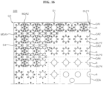
- the reflective sheet 226 may include a first area DA1, a second area DA2, a third area DA3, a fourth area DA4, a central area CDA, an intermediate area MDA1, MDA2, and a triangular area TDA.
- the area DA may be referred to as a dot area DA or a pattern area DA.
- the first area DA1 may be elongated along the first side S1 and/or the fourth side S4.
- a first plurality of holes h may be sequentially formed in the first area DA1 at regular intervals.
- the first area DA1 may be in contact with the first side S1 and/or the fourth side S4.
- the description of the first side S1 and/or the fourth side S4 may be applied to other sides S2 and S3 (see FIG. 7 ).
- the second area DA2 may be elongated along the first side S1 and/or the fourth side S4.
- a second plurality of holes h may be sequentially formed in the second area DA2 at regular intervals.
- the second area DA2 may be in contact with or next to the first area DA1.
- a distance from the first side S1 and/or the fourth side S4 to the second area DA2 may be greater than a distance from the first side S1 and/or the fourth side S4 to the first area DA1.
- the first area DA1 may be positioned between the second area DA2 and the first side S1 and/or the fourth side S4.
- the third area DA3 may be elongated along the first side S1 and/or the fourth side S4.
- a third plurality of holes h may be sequentially formed in the third area DA3 at regular intervals.
- the third area DA3 may be in contact with or next to the second area DA2.
- a distance from the first side S1 and/or the fourth side S4 to the third area DA3 may be greater than a distance from the first side S1 and/or the fourth side S4 to the second area DA2.
- the second area DA2 may be positioned between the third area DA3 and the first area DA1.
- the fourth area DA4 may be elongated along the fourth side S4.
- a fourth plurality of holes h may be sequentially formed in the fourth area DA4 at regular intervals.
- the fourth area DA4 may be in contact with or next to the third area DA3.
- a distance from the first side S1 and/or the fourth side S4 to the fourth area DA4 may be greater than a distance from the first side S1 and/or the fourth side S4 to the third area DA3.
- the third area DA3 may be positioned between the fourth area DA4 and the second area DA2.
- the central area CDA may be an area of the reflective sheet 226 excluding the first area DA1, the second area DA2, the third area DA3, and the fourth area DA4.
- the light pattern DLP may include a phosphor.
- the light pattern DLP may include a red-based phosphor and a green-based phosphor.
- the light pattern DLP may include a yellow-based phosphor.
- the light pattern DLP may have a yellow-based color, when viewed with the naked eye.
- the light pattern DLP may convert blue-based light, provided by the light source 224 (see FIG. 5 ) or the optical assembly 224, into white light.
- the light pattern DLP may have black or gray-based color, when viewed with the naked eye.
- the light pattern DLP may absorb light provided by the light source 224 (see FIG. 5 ) or the optical assembly 224.
- the light pattern DLP may include dots DLP.
- the dots DLP may be disposed around the hole h.
- the dots DLP may be disposed to surround the hole h.
- First dots DLP1 may be disposed around at least one hole h among the first plurality of holes h.
- the first dots DLP1 may be eight in number, and the eight first dots DLP1 may be sequentially arranged around the hole h at regular intervals.
- Second dots DLP2 may be disposed around at least one hole h among the second plurality of holes h.
- the second dots DLP2 may be eight in number, and the eight second dots DLP2 may be sequentially arranged around the hole h at regular intervals.
- Third dots DLP3 may be disposed around at least one hole h among the third plurality of holes h.
- the third dots DLP3 may be eight in number, and the eight third dots DLP3 may be sequentially arranged around the hole h at regular intervals.
- Fourth dots DLP4 may be disposed around at least one hole h among the fourth plurality of holes h.
- the fourth dots DLP4 may be three or four in number, and the four fourth dots DLP4 may be sequentially arranged around the hole h at regular intervals.
- the dots DLP4 around the hole h that is adjacent to the cut-line CL1 may be three in number.
- the dots DLP4 may be excluded from an area adjacent to the cut-line CL1 around the hole h.
- the size of the first dot DLP1 may be greater than the size of the second dot DLP2.
- the size of the second dot DLP2 may be greater than the size of the third dot DLP3.
- the size of the third dot DLP3 may be greater than the size of the fourth dot DLP4.
- the first dot DLP1, the second dot DLP2, the third dot DLP3, and the fourth dot DLP4 may have the same size.
- the number of the dots DLP may increase.
- the intermediate area MDA1 may be positioned between the first plurality of holes h.
- the intermediate area MDA1 may be formed between the first plurality of holes h adjacent to the first side S1.
- the intermediate area MDA1 may be elongated in a direction intersecting or perpendicular to a longitudinal direction of the first side S1.
- the dots DLP1 may be disposed in the intermediate area MDA1.
- a plurality of dots DLP1 may be disposed in a longitudinal direction of the intermediate area MDA1.
- the dots DLP1 may be two in number.
- the intermediate area MDA2 may be positioned between the second plurality of holes h.
- the intermediate area MDA2 may be formed between the second plurality of holes h adjacent to the fourth side S4.
- a plurality of intermediate areas MDA2 may be formed between the second plurality of holes h adjacent to the fourth side S4.
- the intermediate area MDA2 may form a triangular area.
- the dots DLP2 may be disposed in the intermediate area MDA2.
- a plurality of dots DLP2 may be disposed in the intermediate area MDA2.
- the dots DLP2 may be three in number.
- the intermediate area MDA2 may be formed between the first area DA1 and the second area DA2.
- the intermediate area MDA2 may be formed between the second area DA2 and the third area DA3.
- the intermediate area MDA2 may form a generally triangular area TDA extending over the second area DA2 and the third area DA3.
- the description of the second corner C2 may be applied to other corners C1, C3, and C4.
- the reflective sheet 226 may include a first area DA1, a second area DA2, a third area DA3, a fourth area DA4, a central area CDA, and an intermediate area MDA1, MDA2.
- the area DA may be referred to as a dot area DA or a pattern area DA.
- the first area DA1 may be elongated along the first side S1 and/or the fourth side S4.
- a first plurality of holes h may be sequentially formed in the first area DA1 at regular intervals.
- the first area DA1 may be in contact with the first side S1 and/or the fourth side S4.
- the description of the first side S1 and/or the fourth side S4 may be applied to other sides S2 and S3 (see FIG. 7 ).
- the second area DA2 may be elongated along the first side S1 and/or the fourth side S4.
- a second plurality of holes h may be sequentially formed in the second area DA2 at regular intervals.
- the second area DA2 may be in contact with or next to the first area DA1.
- a distance from the first side S1 and/or the fourth side S4 to the second area DA2 may be greater than a distance from the first side S1 and/or the fourth side S4 to the first area DA1.
- the first area DA1 may be disposed between the second area DA2 and the first side S1 and/or the fourth side S4.
- the third area DA3 may be elongated along the first side S1 and/or the fourth side S4.
- a third plurality of holes h may be sequentially formed in the third area DA3 at regular intervals.
- the third area DA3 may be in contact with or next to the second area DA2.
- a distance from the first side S1 and/or the fourth side S4 to the third area DA3 may be greater than a distance from the first side S1 and/or the fourth side S4 to the second area DA2.
- the second area DA2 may be disposed between the third area DA3 and the first area DA1.
- the fourth area DA4 may be elongated along the first side S1 and/or the fourth side S4.
- a fourth plurality of holes h may be sequentially formed in the fourth area DA4 at regular intervals.
- the fourth area DA4 may be in contact with or next to the third area DA3.
- a distance from the first side S1 and/or the fourth side S4 to the fourth area DA4 may be greater than a distance from the first side S1 and/or the fourth side S4 to the third area DA3.
- the third area DA3 may be disposed between the fourth area DA4 and the second area DA2.
- the central area CDA may be an area of the reflective sheet 226 excluding the first area DA1, the second area DA2, the third area DA3, and the fourth area DA4.
- the light pattern DLP may include a phosphor.
- the light pattern DLP may include a red-based phosphor and a green-based phosphor.
- the light pattern DLP may include a yellow-based phosphor.
- the light pattern DLP may have a yellow-based color, when viewed with the naked eye.
- the light pattern DLP may convert blue-based light, provided by the light source 224 (see FIG. 5 ) or the optical assembly 224, into white light.
- the light pattern DLP may have black or gray-based color, when viewed with the naked eye.
- the light pattern DLP may absorb light provided by the light source 224 (see FIG. 5 ) or the optical assembly 224.
- the light pattern DLP may include dots DLP.
- the dots DLP may be disposed around the hole h.
- the dots DLP may be disposed to surround the hole h.
- First dots DLP1 may be disposed around at least one hole h among the first plurality of holes h.
- the first dots DLP1 may be eight in number, and the eight first dots DLP1 may be sequentially arranged around the hole h at regular intervals.
- Second dots DLP2 may be disposed around at least one hole h among the second plurality of holes h.
- the second dots DLP2 may be eight in number, and the eight second dots DLP2 may be sequentially arranged around the hole h at regular intervals.
- Third dots DLP3 may be disposed around at least one hole h among the third plurality of holes h.
- the third dots DLP3 may be eight in number, and the eight third dots DLP3 may be sequentially arranged around the hole h at regular intervals.
- Fourth dots DLP4 may be disposed around at least one hole h among the fourth plurality of holes h.
- the fourth dots DLP4 may be four in number, and the four fourth dots DLP4 may be sequentially arranged around the hole h at regular intervals.
- the size of the first dot DLP1 may be greater than the size of the second dot DLP2.
- the size of the second dot DLP2 may be greater than the size of the third dot DLP3.
- the size of the third dot DLP3 may be greater than the size of the fourth dot DLP4.
- the first dot DLP1, the second dot DLP2, the third dot DLP3, and the fourth dot DLP4 may have the same size.
- the number of the dots DLP may increase.
- the intermediate area MDA1 may be located between the first plurality of holes h.
- the intermediate area MDA1 may be formed between the first plurality of holes h adjacent to the fourth side S4.
- the intermediate area MDA1 may be elongated in a direction intersecting or perpendicular to a longitudinal direction of the fourth side S4.
- the dots DLP1 may be disposed in the intermediate area MDA1.
- a plurality of dots DLP1 may be disposed in a longitudinal direction of the intermediate area MDA1.
- the dots DLP1 may be two in number.
- the intermediate area MDA2 may be located between the first plurality of holes h.
- the intermediate area MDA2 may be formed between the first plurality of holes h adjacent to the first side S1.
- a plurality of intermediate areas MDA2 may be formed between the first plurality of holes h adjacent to the first side S1.
- the intermediate area MDA2 may form a triangular area.
- the dots DLP1 may be disposed in the intermediate area MDA2.
- a plurality of dots DLP1 may be disposed in the intermediate area MDA2.
- the dots DLP1 may be three in number.
- the intermediate area MDA1 may be located between the second plurality of holes h.
- the intermediate area MDA1 may be formed between the second plurality of holes h adjacent to the fourth side S4.
- the intermediate area MDA1 may be elongated in a direction intersecting or perpendicular to a longitudinal direction of the fourth side S4.
- the dots DLP2 may be disposed in the intermediate area MDA1.
- a plurality of dots DLP2 may be disposed in a longitudinal direction of the intermediate area MDA1.
- the dots DLP2 may be two in number.
- the intermediate area MDA2 may be located between the second plurality of holes h.
- the intermediate area MDA2 may be formed between the second plurality of holes h adjacent to the first side S1.
- a plurality of intermediate areas MDA2 may be formed between the second plurality of holes h adjacent to the first side S1.
- the intermediate area MDA2 may form a triangular area.
- the dots DLP2 may be disposed in the intermediate area MDA2.
- a plurality of dots DLP2 may be disposed in the intermediate area MDA2.
- the dots DLP2 may be three in number.
- the intermediate area MDA1 may be located between the third plurality of holes h.
- the intermediate area MDA1 may be formed between the third plurality of holes h adjacent to the fourth side S4.
- the intermediate area MDA1 may be elongated in a direction intersecting or perpendicular to a longitudinal direction of the fourth side S4.
- the dots DLP3 may be disposed in the intermediate area MDA1.
- a plurality of dots DLP3 may be disposed in a longitudinal direction of the intermediate area MDA1.
- the dots DLP3 may be two in number.
- the intermediate area MDA2 may be located between the third plurality of holes h.
- the intermediate area MDA2 may be formed between the third plurality of holes h adjacent to the first side S1.
- a plurality of intermediate areas MDA2 may be formed between the third plurality of holes h adjacent to the first side S1.
- the intermediate area MDA2 may form a triangular area.
- the dots DLP3 may be disposed in the intermediate area MDA2.
- a plurality of dots DLP3 may be disposed in the intermediate area MDA2.
- the dots DLP3 may be three in number.
- the intermediate area MDA2 may be formed between the first area DA1 and the second area DA2.
- the intermediate area MDA2 may be formed between the second area DA2 and the third area DA3.
- the description of the second corner C2 may be applied to other corners C1, C3, and C4.
- an inner frame 310, 330 may be coupled to sides LS1, LS2, SS1, and SS2 or edges LS1, LS2, SS1, and SS2 of the rear frame 130.
- the inner frame 310, 330 may include a plurality of parts 310 and 330.
- a first part 310 may be coupled to the first long side LS1 of the rear frame 130.
- a second part 310 may be coupled to the second long side LS2 of the rear frame 130.
- a third part 330 may be coupled to the first short side SS1 of the rear frame 130.
- a fourth part 330 may be coupled to the second short side SS2 of the rear frame 130.
- the first part 310 may be coupled to the third part 330 and the fourth part 330, and the second part 310 may be coupled to the third part 330 and the fourth part 330.
- the first part 310, the second part 310, the third part 330, or the fourth part 330 may be referred to as the inner frame 310, 330.
- the inner frame 310 may be elongated and may have a bar shape that is curved at both ends.
- a center part 311 may be elongated and may have a rectangular cross-section.
- a support surface 311a may form one surface of the center part 311.
- a frame wall 313 may protrude from the support surface 311a and may be elongated in a longitudinal direction of the center part 311.
- a plurality of frame walls 313 may be formed side by side.
- a first frame wall 313a may be spaced apart from a second frame wall 313b.
- An accommodation portion 314 may be formed on the frame wall 313.
- the accommodation portion 314 may be formed as a flat surface at an upper end of the frame wall 313.
- a length of the accommodation portion 314 may be smaller than a length of the frame wall 313.
- a recessed portion 316 may be formed in the support surface 311a.
- the recessed portion 316 may be stepped downward from the support surface 311a.
- a cover wall 315 may be formed on one side of the recessed portion 316.
- the cover wall 315 may be disposed in alignment with an extension line of the first frame wall 313a.
- a pad AD or an adhesive pad AD may be fixed to the recessed portion 316, and the pad AD or the adhesive pad AD may support the optical layer 129 (see FIG. 3 ).
- a side part 312 may extend while being bent from one or both ends of the center part 311.
- the support surface 311a may form one surface of the side part 312.
- a coupling rib 319 may protrude from one end of the side part 312.
- the recessed portion 318 may be stepped downward from the support surface 311a of the side part 312.
- the cover wall 317 may be disposed on one side of the recessed portion 318 of the side part 312, and may be connected to the cover wall 315 of the center part 311.
- a coupling rib 321, 322 may protrude from the support surface 311a of the center part 311 and may be provided in plurality.
- a first coupling rib 321 may protrude from the support surface 311a of the center part 311 and may be elongated in a longitudinal direction of the center part 311.
- a second coupling rib 322 may be disposed next to the first coupling rib 321, and may be disposed in alignment with an extension line of the first coupling rib 321.
- a third frame wall 313c may extend from the first frame wall 313a and/or the second frame wall 313b.
- the third frame wall 313c may be disposed adjacent to the first coupling rib 321 and the second coupling rib 322, and may be in contact with one edge of the center part 311.
- the height of the third frame wall 313c may be smaller than the height of the first frame wall 313a and/or the second frame wall 313b.
- the inner frame 310 may include a middle coupler 324, 325.
- the middle coupler 324, 325 may be disposed on an outer surface of the center part 311.
- the middle coupler 324, 325 may be provided in plurality.
- a first middle coupler 324 may be defined by slots S or slits S formed by cutting out an outer surface 323 of the center part 311.
- a first middle coupler 324, 325 may include a locking protrusion 324 protruding from the outer surface 323 of the center part 311.
- the locking protrusion 324 may be formed adjacent to a distal end of the first middle coupler 324, 325 in a longitudinal direction of the center part 311.
- a coupling hole 325 may pass through the first middle coupler 324, 325 to be formed between the support surface 311a and the locking protrusion 324.
- a protrusion 132 of the frame 130 may be inserted into the coupling hole 325 of the first middle coupler 324, 325.
- a second middle coupler 324 may be positioned next to the first middle coupler 324, 325 in the longitudinal direction of the center part 311.
- the second middle coupler 324 may include a locking protrusion 324 protruding from the outer surface of the center part 311.
- the locking protrusion 324 may be formed adjacent to a distal end of the second middle coupler 324 in the longitudinal direction of the center part 311.
- the pad AD or the adhesive pad AD may be positioned in or fixed to the accommodation portion 314.
- a third middle coupler 324, 325 may include a locking protrusion 324 protruding from the outer surface 323 of the side part 312.
- the locking protrusion 324 may be formed adjacent to a distal end of the third middle coupler 324, 325.
- the coupling hole 325 may pass through the third middle coupler 324, 325 to be formed between the support surface 311a and the locking protrusion 324.
- the protrusion 132 of the frame 130 may be inserted into the coupling hole 325 of the third middle coupler 324, 325.
- a fourth middle coupler 326 may be disposed next to the third middle coupler 324, 325 in a longitudinal direction of the side part 312.
- the fourth middle coupler 326 may include a locking protrusion 326 protruding from the outer surface 323 of the side part 312.
- the locking protrusion 326 may be formed adjacent to a distal end of the fourth middle coupler 326 in the longitudinal direction of the side part 312.
- a slot S may be formed between the third middle coupler 324, 325 and the fourth middle coupler 326.
- the inner frame 330, 331 may include a support surface 331a and a side wall 332.
- the support surface 331a may form one surface of a third part 331 and/or a fourth part 331.
- a coupling recess 334 may be formed in the support surface 331a of the inner frame 330, 331.
- the rear frame 130 and the inner frame 330 may be coupled by a screw SC inserted into the coupling recess 334.
- An accommodation portion 333 may be formed by recessing or cutting out the upper surface of the sidewall 332.
- the pad AD or the adhesive pad AD may be disposed on or fixed to the accommodation portion 333.
- the optical layer 123 may be placed on the inner frame 310, 330.
- An outer frame 400 may be coupled to the inner frame 310, 330 while covering the periphery of the optical layer 123.
- the outer frame 400 may be referred to as a guide panel 400.
- An outer frame 410, 420, 430 may be coupled to the first short side SS1, the first long side LS1, and/or the second short side SS2 as the elongated frame 400 is bent.
- a separate outer frame 440 may be coupled to the second long side LS2.
- a first part 410 of the outer frame 400 may include a horizontal portion 411 and a vertical portion 412. The description of the first part 410 may be applied to the second part 420 and/or the third part 430.
- the horizontal portion 411 may have an elongated plate shape.
- the vertical portion 412 may have a plate shape that is bent and elongated from the horizontal portion 411.
- a rib hole 415 may be formed in the horizontal portion 411. There may be a plurality of rib holes 415.
- a first rib hole 415a may be an elongated long hole.
- a second rib hole 415b may be a long hole and may be disposed in a longitudinal direction of the first rib hole 415a.
- the rib holes 415 may be formed through the horizontal portion 411.
- a guide rib 414 may protrude from the horizontal portion 411 to be elongated.
- the guide rib 414 may be parallel to the vertical portion 412.
- the rib holes 415 may be positioned between the guide ribs 414.
- a hook line 413 may be formed at the vertical portion 412. The hook line 413 may be adjacent to the guide rib 414 or may face the guide rib 414.
- the first part 410 may include a horizontal portion 411 and a vertical wall 412W.
- the vertical wall 412W may have a constant height from the horizontal portion 411.
- the third part 430 may include a horizontal portion 431 and a vertical wall 432W.
- the vertical wall 432W may have a constant height from the horizontal portion 431.
- the vertical wall 412W of the first part 411 may be connected to the vertical wall 432W of the third part 430.
- a corner formed by the vertical wall 412W of the first part 411 and the vertical wall 432W of the third part 430 may be rounded.
- the vertical wall 412W of the first part 410 may form a gap with the vertical wall 432W of the third part 430.
- the outer frame 400 may be coupled to the rear frame 130 and/or the inner frame 310, 330 (see FIG. 17 ) while covering the optical sheet 125.
- the horizontal portion 411 of the outer frame 400 may be placed on the optical sheet 125, and the coupling ribs 321 and 322 to which the optical sheet 125 is coupled may be inserted into the rib hole 415.
- the pad AD or the adhesive member AD may be positioned on or fixed to the horizontal portion 411 of the outer frame 400.
- the pad AD may be a double-sided tape having a constant thickness.
- the display panel 110 (see FIG. 30 ) may be placed on the outer frame 400 and may be fixed to the horizontal portion 411 by the pad AD.
- the center frame 311 of the inner frame 310 may be coupled to one side of the rear frame 130.
- a distal end of the bent rear frame 130 may be inserted into the center frame 311 of the inner frame 310.
- the protrusion 132 protruding to the outside of the rear frame 130 may be inserted into he coupling hole 325 of the inner frame 310.
- the outer frame 410 may include a line groove 419.
- the line groove 419 may be formed in the vertical portion 412 of the outer frame 410.
- the locking protrusion 324 of the inner frame 310 may be inserted into the line groove 419 of the outer frame 410.
- the locking protrusion 324 of the inner frame 310 may be engaged with the hook line 413 of the outer frame 410.
- the guide rib 414 of the outer frame 410 may be inserted into the inner frame 310.
- the guide rib 414 may be inserted and fixed into the inner frame 310 as the outer frame 410 is placed on the inner frame 310.
- the optical layer 123 and the optical sheet 125 may be placed on the support surface 311a of the inner frame 310 and may be positioned between the support surface 311a of the inner frame 310 and the horizontal portion 411 of the outer frame 410.
- the display panel 110 may be placed on the horizontal portion 411 of the outer frame 410, and the vertical wall 412W may cover the side surface of the display panel 110.
- the frame 130 may include a rear plate 131 and a bending part 133.
- the rear plate 131 may be disposed at the rear of the display panel 110 and may face the display panel 110.
- the bending part 133 may be bent and extend from the rear plate 131.
- the inner frame 310, 330 may be coupled to the frame 130.
- the bending part 133 may be inserted into the inner frame 310, 330.
- the inner frame 310, 330 may include the support surface 311a, the frame wall 331, a front leg 311b, and a middle leg 311c.
- the support surface 311a may be elongated and may be parallel to or face the rear plate 131 of the frame 130.
- the optical layer 123 may be placed on the support surface 311a of the inner frame 310, 330.
- the optical sheet 125 may be stacked on the optical layer 123.
- the frame wall 313 may protrude above the support surface 311a and may be elongated in a direction of extension of the support surface 311a.
- the frame wall 313 may cover the side surface of the optical sheet 125 and the optical layer 123 and may face the side surface.
- the optical sheet 125 may be spaced apart from the frame wall 313 by a first distance B.
- the middle coupler 324 may be elongated from the frame wall 313 and may face or contact the bending part 133.
- the middle leg 311c may extend from the support surface 311a and may be parallel to the middle coupler 324.
- the middle leg 311c may be supported on the rear plate 131 of the frame 130.
- a gap or space may be formed between the middle leg 311c and the middle coupler 324, and the bending part 133 of the frame 130 may be inserted between the middle leg 311c and the middle coupler 324.
- the front leg 311b may be elongated from the support surface 311a and may be parallel to the middle leg 311c.
- a gap or space may be formed between the front leg 311b and the middle leg 311c.
- the front leg 311b may be supported on the rear plate 131 of the frame 130.
- the outer frame 400 may include a vertical portion 411 and a horizontal portion 412.
- the vertical portion 412 may cover the middle coupler 324 of the inner frame 310, 330.
- the vertical portion 412 may face or contact the middle coupler 324.
- the horizontal portion 412 may be connected to the vertical portion 412 and may cover the frame wall 313 of the inner frame 310, 330 and the optical sheet 125.
- a pad 416 may be disposed between the horizontal portion 411 and the optical sheet 125 and may be fixed or adhered to the horizontal portion 411. The pad 416 may allow the optical layer 123 and/or the optical sheet 125 to come into close contact with the support surface 311a of the inner frame 310, 330.
- the substrate 222 may be placed on the rear plate 131 of the frame 130.
- the reflective sheet 226 may be placed on the substrate 222.
- a side reflector 500 may be coupled or fixed to the front leg 311b of the inner frame 310, 330.
- the side reflector 500 may be elongated to cover the front leg 311b of the inner frame 310, 330.
- the side reflector 500 may include a white material.
- the reflective sheet 226 may also cover the outer surface of the side reflector 500.
- a fluorescent material may be applied to the outer surface of the side reflector 500.
- the fluorescent material may include a green-based and/or red-based phosphor. Accordingly, a yellowish phenomenon occurring in an area adjacent to the side surface of the optical layer 123 may be improved.
- a second distance A between the front leg 311b and the middle leg 311c may be substantially equal to a first distance B between the side surface of the optical layer 123 and the frame wall 313.
- the optical layer 123 is bent due to thermal expansion of the optical layer 123. As the optical layer 123 is bent, the optical sheet 125 rubs against the outer frame 400, causing scratches and damaging the alignment of the display panel 110. The damage to the optical layer 123 and the optical sheet 125 may deteriorate the image quality of the display device.
- the optical layer 123 is contracted, such that the optical layer 123 may be peeled off from the seating surface 311a.
- an image defect may occur.
- the side reflector 500 may include a first surface 510, a second surface 520, a third surface 530, a fourth surface 540, a fifth surface 550, and a base surface 501.
- the base surface 501 may be parallel to or face the substrate 222 and/or the rear plate 131.
- the base surface 501 may be spaced apart from the substrate 222.
- the first surface 510 may extend from the base surface 501.
- the first surface 510 may form an outer surface.
- the first surface 510 may be referred to as a side surface 510.
- the first surface 510 may form a second angle theta 2 with respect to the base surface 501.
- the second angle theta 2 may be an acute angle.
- the second angle theta 2 may range from 85 to 90 degrees.
- the first surface 510 may include a plurality of surfaces.
- the first surface 510 may form a polygonal surface.
- the first surface 510 may include a lower surface 511 and an upper surface 512.
- the lower surface 511 may be connected to the base surface 501, and the upper surface 512 may be connected to the second surface 520.
- the upper surface 512 may be a surface having a predetermined angle with respect to the lower surface 511.
- the predetermined angle may be an obtuse angle.
- the second surface 520 may be connected to the first surface 510.
- the second surface 520 may be referred to as a first inclined surface 520.
- the second surface 520 may form a predetermined first angle theta 1 with respect to the first surface 510.
- the first angle theta 1 may be an obtuse angle.
- the first angle theta 1 may range from 110 to 130 degrees.
- the first angle theta 1 may range from 115 to 125 degrees.
- the first angle theta 1 may be greater than the second angle theta 2.
- the second surface 520 may reflect light to the optical layer 123.
- the third surface 530 may be connected to the second surface 520.
- the third surface 530 may be referred to as a second inclined surface 530.
- the third surface 530 may form a predetermined third angle theta 3 with respect to the second surface 520.
- the third angle theta 3 may be an obtuse angle.
- the third angle theta 3 may be greater than the first angle theta 1.
- the third surface 530 may support the optical layer 123.
- the third surface 530 may reflect light to the optical layer 123.
- the first surface 510, the second surface 520, and/or the third surface 530 may be reflecting surfaces.
- the fourth surface 540 may be connected to the third surface 530, and the fifth surface 550 may be connected to the base surface 501.
- the fifth surface 550 may contact the fourth surface 540.
- the fourth surface 540 and the fifth surface 550 may be recessed inward of the side reflector 500.
- the fourth surface 540 and/or the fifth surface 550 may be in contact with or adhered to the front leg 311b of the inner plate 310, 330.
- the fourth surface 540 and/or the fifth surface 550 may be adhesion surfaces.
- a boundary between the second surface 520 and the third surface 530 may be disposed in alignment with an extension line of the fifth surface 550.
- the second surface 520 may correspond to the active area AA of the display panel 110
- the third surface 530 may correspond to the de-active area DA of the display panel 110.
- the inner frame 310, 330 may include the frame wall 313 and the support part 311a.
- the support part 311a may be referred to as the support surface 311a.
- the frame wall 313 may extend in a thickness direction intersecting the longitudinal direction of the display panel 110.
- the support part 311a may extend in a direction parallel to the longitudinal direction of the display panel 110.
- the support part 311a may intersect the frame wall 313.
- the inner frame 310, 330 may include the front leg 311b and the middle leg 311c.
- the front leg 311b may extend downward from the support part 311a, in parallel with the frame wall 313.
- the front leg 311b may be opposite the frame wall 313 with respect to the support part 311a.
- the middle leg 311c may be disposed between the front leg 311b and the frame wall 313.
- the middle leg 311c may extend parallel to the front leg 311b and/or the frame wall 313.
- the inner frame 310, 330 may include a sub-support part 340.
- the sub-support part 340 may be formed on the outer surface of the front leg 311b.
- the sub-support part 340 may be formed as one body with the front leg 311b.
- the sub-support part 340 may include an inclined surface 341, a round surface 342, a side surface 343, a tapered surface 346, and a lower surface 347.
- the inclined surface 341 may extend from the support surface 311a.
- the inclined surface 341 may be inclined with respect to the support surface 311a.
- a gap may be formed between the inclined surface 341 and the rear surface of the optical layer 123.
- the inclined surface 341 may be inclined at 30 to 60 degrees with respect to the support surface 311a.
- a boundary between the support surface 311a and the inclined surface 341 may be aligned with the boundary between the active area AA and the de-active area DA of the display panel 110.
- the round surface 342 may extend from the inclined surface 341.
- the round surface 342 may have a predetermined curvature.
- the side surface 343 may extend from the round surface 342 and may be parallel to the front leg 311b and/or the frame wall 313.
- the lower surface 347 may be parallel to the rear surface of the optical layer 123 and may protrude from the front leg 311b to extend in a direction intersecting a longitudinal direction of the front leg 311b.
- the tapered surface 346 may connect the side surface 343 and the lower surface 347.
- the tapered surface 346 may be formed by tapering a corner edge at which the side surface 343 and the lower surface 347 meet.
- the tapered surface 346 may overlap the substrate 222 and/or a distal end of the reflective sheet 226.
- An outer surface of the sub-support part 340 may be coated with a reflective material.
- a first distance B from the side surface of the optical layer 123 to the frame wall 313 may be greater than a second distance A by which the optical layer 123 and the support surface 311a overlap.
- the second distance A may be greater than a third distance C between the side surface 343 of the sub-support part 340 and the front leg 311b.
- a sum of the second distance A and the third distance C may correspond to the first distance B.
- the sum of the second distance A and the third distance C may be substantially equal to the first distance B.
- the optical layer 123 may be stably placed on the support surface 311a.
- a distance that the side surface of the optical layer 123 extends toward the frame wall 313 when the optical layer 123 is expanded may be smaller than the first distance B.
- a distance that the side surface of the optical layer 123 moves away from the frame wall 313 when the optical layer 123 is contracted may be smaller than the third distance C.
- light provided by the optical assembly 224 is reflected by the side surface 343, the round surface 342, and the inclined surface 341 of the sub-support part 340, and enters a gap formed between the optical layer 123 and the sub-support part 340, such that the light may be provided uniformly to a distal end of the active area AA of the display panel 110.
- the light reflected from the substrate 222 and the reflective sheet 226 may be recycled by the tapered surface 346.
- the inner frame 310, 330 may include the frame wall 313 and the support part 311a.
- the support part 311a may be referred to as the support surface 311a.
- the frame wall 313 may extend in a thickness direction intersecting the longitudinal direction of the display panel 110.
- the support part 311a may extend in a direction parallel to the longitudinal direction of the display panel 110.
- the support part 311a may intersect the frame wall 313.
- the inner frame 310, 330 may include the front leg 311b and the middle leg 311c.
- the front leg 311b may extend downward from the support part 311a, in parallel with the frame wall 313.
- the front leg 311b may be opposite the frame wall 313 with respect to the support part 311a.
- the middle leg 311c may be disposed between the front leg 311b and the frame wall 313.
- the middle leg 311c may extend parallel to the front leg 311b and/or the frame wall 313.
- the inner frame 310, 330 may include a sub-support part 340.
- the sub-support part 340 may be formed on the outer surface of the front leg 311b.
- the sub-support part 340 may be formed as one body with the front leg 311b.
- the sub-support part 340 may include an inclined surface 341, a round surface 342, a side surface 343, and a foot 345.
- the inclined surface 341 may extend from the support surface 311a.
- the inclined surface 341 may be inclined with respect to the support surface 311a.
- a gap may be formed between the inclined surface 341 and the rear surface of the optical layer 123.
- the inclined surface 341 may be inclined at 30 to 60 degrees with respect to the support surface 311a.
- a boundary between the support surface 311a and the inclined surface 341 may be aligned with the boundary between the active area AA and the de-active area DA of the display panel 110.
- the round surface 342 may extend from the inclined surface 341.
- the round surface 342 may have a predetermined curvature.
- the side surface 343 may extend from the round surface 342 and may be parallel to the front leg 311b and/or the frame wall 313.
- the foot 345 may protrude from the side surface 343.
- the foot 345 may extend in a direction parallel to the substrate 222 and/or the reflective sheet 226.
- the foot 345 may overlap the substrate 222 and/or the reflective sheet 226.
- the foot 345 may press the substrate 222 and/or the reflective sheet 226.
- the foot 345 may be disposed between the optical assembly 224 and the optical assembly 224.
- the foot 345 may be disposed between the hole h and the hole h of the reflective sheet 226 in which the optical assembly 224 is disposed.
- the reflective sheet 226 may be stably secured by the foot 345.
- the round surface 344 may connect the foot 345 and the side surface 343.
- An outer surface of the sub-support part 340 may be coated with a reflective material.
- a first distance B from the side surface of the optical layer 123 to the frame wall 313 may be greater than a second distance A by which the optical layer 123 and the support surface 311a overlap.
- the second distance A may be greater than a third distance C between the side surface 343 of the sub-support part 340 and the front leg 311b.
- a sum of the second distance A and the third distance C may correspond to the first distance B.
- the sum of the second distance A and the third distance C may be substantially equal to the first distance B.
- the optical layer 123 may be stably placed on the support surface 311a.
- a distance that the side surface of the optical layer 123 extends toward the frame wall 313 when the optical layer 123 is expanded may be smaller than the first distance B.
- a distance that the side surface of the optical layer 123 moves away from the frame wall 313 when the optical layer 123 is contracted may be smaller than the third distance C.
- the optical assembly 224 Accordingly, light provided by the optical assembly 224 is reflected by the side surface 343, the round surface 342, and the inclined surface 341 of the sub-support part 340, and enters a gap formed between the optical layer 123 and the sub-support part 340, such that the light may be provided uniformly to a distal end of the active area AA of the display panel 110.
- the substrate 222 and/or the optical sheet 226 may be stably secured even when the substrate 222 and/or the optical sheet 226 is expanded or contracted by heat.
- a display device includes: a display panel 110; a frame 130 disposed at a rear of the display panel 110; a substrate 222 disposed on the frame 130 and having a light source 224 that provides light; an inner frame 310, 330 coupled to the frame 130 and supporting the display panel 110; and an optical layer 123 disposed between the display panel 110 and the inner frame 310, 330, the optical layer 123 placed on the inner frame 310, 330, wherein the inner frame 310, 330 includes: a support part 311a on which the optical layer 123 is placed; and a sub-support part 340 disposed between the optical layer 123 and the frame 130, the sub-support part 340 formed on the inner frame 310, 330, wherein the sub-support part 340 includes: a lower surface 347 disposed adjacent to the substrate 222; an inclined surface 341 disposed adjacent to a lower surface of the optical layer 123, the inclined surface 341 reflecting the light, provided by the light source 224, to the
- the sub-support part 340 may further include a round surface 342 connecting the side surface 343 and the inclined surface 341, wherein the inclined surface 341 and the side surface 343 may form an obtuse angle.
- the sub-support part 340 may further include a tapered surface 346 connecting the side surface 343 and the lower surface 347, wherein the tapered surface 346 may overlap the substrate 222.
- the display panel 110 may include: an active area AA on which an image is displayed; and a de-active area DA formed around the active area AA, wherein the support part 311a of the inner frame 310, 330 may be aligned with the de-active area, and the sub-support part 340 of the inner frame 310, 330 may be aligned with the active-area AA.
- the inner frame 310, 330 may include a frame wall 313 that is opposite a side surface of the optical layer 123 with respect to the support part 311a, wherein a first distance B from the frame wall 313 to the side surface of the optical layer 123 may be greater than a second distance A by which the optical layer 123 and the support part 311a overlap.
- the second distance A may be greater than a third distance C which is a length of a lower surface of the sub-support part 311a.
- a sum of the second distance A and the third distance C may be substantially equal to the first distance B.
- the sub-support part 340 may further include a foot 345 that extends by protruding from the side surface 343 of the sub-support part 340, the foot 345 having a bottom that forms the lower surface and having an upper surface connected to the side surface 343, wherein the foot 345 may overlap an upper surface of the substrate 222.
- the substrate 222 may include a plurality of light sources 224, wherein the plurality of light sources 224 may be spaced apart from each other, and the foot 345 may be disposed between the plurality of light sources 224.
- the optical layer 123 When being contracted, the optical layer 123 may be supported by the sub-support part 340.
- a configuration "A” described in one embodiment of the disclosure and the drawings and a configuration "B” described in another embodiment of the disclosure and the drawings may be combined with each other. Namely, although the combination between the configurations is not directly described, the combination is possible except in the case where it is described that the combination is impossible.
Landscapes
- Physics & Mathematics (AREA)
- Nonlinear Science (AREA)
- General Physics & Mathematics (AREA)
- Optics & Photonics (AREA)
- Crystallography & Structural Chemistry (AREA)
- Chemical & Material Sciences (AREA)
- Mathematical Physics (AREA)
- Engineering & Computer Science (AREA)
- General Engineering & Computer Science (AREA)
- Theoretical Computer Science (AREA)
- Computer Hardware Design (AREA)
- Human Computer Interaction (AREA)
- Liquid Crystal (AREA)
Abstract
Description
- The following description relates to a display device.
- With the development of the information society, there have been growing demands for various types of display devices, and in order to meet these demands, various display devices, such as a liquid crystal display (LCD) device, organic light emitting diodes (OLED), a Micro LED, etc., have been researched and used recently.
- Among them, the liquid crystal panel of the LCD includes a liquid crystal layer, and a TFT substrate and a color filter substrate that are opposite each other with the liquid crystal layer interposed therebetween, and may display an image by using light provided by a backlight unit.
- Recently, as interest in image quality of a display device increases, color expression or color reproducibility close to true color has received considerable attention, and much research has been devoted to improving image quality to improve light uniformity and to realize true color.
- It is an object of the present disclosure to solve the above and other problems.
- It is another object of the present disclosure to provide a display device having a coupling structure capable of accommodating thermal expansion and/or contraction of a backlight unit.
- It is yet another object of the present disclosure to provide a display device having a firm coupling structure while reducing optical depth.
- It is still another object of the present disclosure to provide a display device capable of improving luminance and optical uniformity of a backlight unit.
- It is further another object of the present disclosure to provide a coupling structure of a display device capable of improving luminance and optical uniformity.
- In accordance with an aspect of the present disclosure, the above and other objects can be accomplished by providing a display device including: a display panel; a frame disposed at a rear of the display panel; a substrate disposed on the frame and having a light source that provides light; an inner frame coupled to the frame and supporting the display panel; and an optical layer disposed between the display panel and the inner frame, the optical layer placed on the inner frame, wherein the inner frame includes: a support part on which the optical layer is placed; and the sub-support part disposed between the optical layer and the frame, the sub-support part formed on the inner frame, wherein the sub-support part includes: a lower surface disposed adjacent to the substrate; an inclined surface disposed adjacent to a lower surface of the optical layer, the inclined surface reflecting the light, provided by the light source, to the optical layer; and a side surface connecting the lower surface and the inclined surface, the side surface reflecting the light provided by the light source.
- The display device according to the present disclosure has the following effects.
- According to at least one of the embodiments of the present disclosure, a display device having a coupling structure capable of accommodating thermal expansion and/or contraction of a backlight unit may be provided.
- According to at least one of the embodiments of the present disclosure, a display device having a firm coupling structure while reducing optical depth may be provided.
- According to at least one of the embodiments of the present disclosure, a display device capable of improving luminance and optical uniformity of a backlight unit may be provided.
- According to at least one of the embodiments of the present disclosure, a coupling structure of a display device capable of improving luminance and optical uniformity may be provided.
- Further scope of applicability of the present disclosure will become apparent from the detailed description given hereinafter. However, it should be understood that the detailed description and specific examples, while indicating preferred embodiments of the present disclosure, are given by illustration only, since various changes and modifications within the spirit and scope of the present disclosure will become apparent to those skilled in the art from this detailed description.
-
FIGS. 1 to 36 are diagrams illustrating examples of a display device according to embodiments of the present disclosure. - Hereinafter, the present disclosure will be described in detail with reference to the accompanying drawings, in which the same reference numerals are used throughout the drawings to designate the same or similar components, and a redundant description thereof will be omitted.
- The suffixes, such as "module" and "unit," for elements used in the following description are given simply in view of the ease of the description, and do not have a distinguishing meaning or role.
- In addition, it will be noted that a detailed description of known arts will be omitted if it is determined that the detailed description of the known arts can obscure the embodiments of the present disclosure.
- Further, the accompanying drawings are used to help easily understand various technical features and it should be understood that the embodiments presented herein are not limited by the accompanying drawings. As such, the present disclosure should be construed to extend to any alterations, equivalents and substitutes in addition to those which are particularly set out in the accompanying drawings.
- The following description will be made using a liquid crystal display (LCD) device as an example of a display panel, but the display panel that is applicable to the present disclosure is not limited to the LCD device.
- Referring to
FIG. 1 , a display device may include a first long side LS1, a second long side LS2 opposite to the first long side LS1, a first short side SS1 adjacent to one end of each of the first long side LS1 and the second long side LS2, and a second short side SS2 opposite to the first short side SS1. - Here, an area of the first short side SS1 may be referred to as a first side area, an area of the second short side SS2 may be referred to as a second side area opposite to the first side area, an area of the first long side LS1 may be referred to as a third side area adjacent to the first side area and the second side area and disposed between the first side area and the second side area, and an area of the second long side LS2 may be referred to as a fourth side area adjacent to the first side area and the second side area, disposed between the first side area and the second side area, and opposite to the third side area.
- It is illustrated and described that the first and second long sides LS1 and LS2 are longer than the first and second short sides SS1 and SS2, but it is also possible that the lengths of the first and second long sides LS1 and LS2 may be approximately equal to the lengths of the first and second short sides SS1 and SS2.
- A first direction DR1 may be a direction parallel to the long sides LS1 and LS2 of the
display device 100, and a second direction DR2 may be a direction parallel to the short sides SS1 and SS2 of thedisplay device 100. A third direction DR3 may be a direction perpendicular to the first direction DR1 and/or the second direction DR2. - The first direction DR1 and the second direction DR2 may be collectively referred to as a horizontal direction. Further, the third direction DR3 may be referred to as a vertical direction.
- A side or a surface, on which the display device displays an image, may be referred to as a forward direction or a front side or a front surface. When the display device displays an image, a side or a surface, at which the image cannot be observed, may be referred to as a rearward direction or a rear side or a rear surface.
- When the display device is viewed from the forward direction or the front side or the front surface, the first long side LS1 may be referred to as an upper side or an upper surface. Likewise, the second long side LS2 may be referred to as a lower side or a lower surface. Likewise, the first short side SS1 may be referred to as a right side or a right surface, and the second short side SS2 may be referred to as a left side or a left surface.
- The first long side LS1, the second long side LS2, the first short side SS1, and the second short side SS2 may be referred to as edges of the display device. Further, positions where the first long side LS1, the second long side LS2, the first short side SS1, and the second short side SS2 meet each other may be referred to as corners. For example, a position where the first long side LS1 and the first short side SS1 meet may be referred to as a first corner C1, a position where the first long side LS1 and the second short side SS2 meet may be referred to as a second corner C2, a position where the second short side SS2 and the second long side LS2 each other may be referred to as a third corner C3, and a position where the second long side LS2 and the first short side SS1 meet may be referred to as a fourth corner C4.
- A direction from the first short side SS1 to the second short side SS2 or a direction from the second short side SS2 to the first short side SS1 may be referred to as a left-right direction LR. A direction from the first long side LS1 to the second long side LS2 or a direction from the second long side LS2 to the first long side LS1 may be referred to as an up-down direction UD.
- Referring to
FIG. 2 , afront cover 105 may cover at least a portion of the front and side surfaces of adisplay panel 110. Thefront cover 105 may be divided into a front cover located on the front surface of thedisplay panel 110, and a side cover located on the side surface of thedisplay panel 110. Either one of the front cover or the side cover may be omitted. - The
display panel 110 may be provided on the front surface of thedisplay device 100 and may display an image. Thedisplay panel 110 may display an image in such a manner that a plurality of pixels output red, green or blue (RGB) for each pixel according to the timing. Thedisplay panel 110 may be divided into an active area, on which an image is displayed, and a de-active area on which an image is not displayed. Thedisplay panel 110 may include a front substrate and a rear substrate which are disposed opposite each other with a liquid crystal layer interposed therebetween. - The front substrate may include a plurality of pixels composed of red (R), green (G), and blue (B) subpixels. The front substrate may emit light corresponding to red, green, or blue color in response to a control signal.
- The rear substrate may include switching elements. The rear substrate may switch on or off pixel electrodes. For example, the pixel electrode may change a molecular arrangement of a liquid crystal layer in response to a control signal received from the outside. The liquid crystal layer may include liquid crystal molecules. The arrangement of the liquid crystal molecules may change depending on a difference in voltage generated between the pixel electrode and a common electrode. The liquid crystal layer may allow or interrupt the transmission of the light from a
backlight unit 120 to the front substrate. - The
backlight unit 120 may be disposed at the rear of thedisplay panel 110. Thebacklight unit 120 may include light sources. Thebacklight unit 120 may be coupled to aframe 130 in front of theframe 130. Theframe 130 may be referred to as arear frame 130 or amain frame 130. - The
backlight unit 120 may be driven by a full driving scheme or a partial driving scheme, such as local dimming, impulsive driving, or the like. The backlight unit 120 may include anoptical sheet 125 and anoptical layer 123. Theoptical layer 123 may be referred to as anoptical module 123 or anoptical unit 123. - The
optical sheet 125 may allow light from the light source to be evenly transmitted to thedisplay panel 110. Theoptical sheet 125 may be composed of a plurality of layers. For example, theoptical sheet 125 may include a prism sheet, a diffusion sheet, and the like. - The
optical sheet 125 may include acoupling part 125d. Thecoupling part 125d may be coupled to thefront cover 105, theframe 130, and/or aback cover 150. Alternatively, thecoupling part 125d may be fastened to a structure formed on or coupled to thefront cover 105, theframe 130, and/or theback cover 150. - The
frame 130 may serve to support components of thedisplay device 100. For example, components, such as thebacklight unit 120 and the like, may be coupled to theframe 130. For example, theframe 130 may be made of a metal material, such as an aluminum alloy and the like. - The
back cover 150 may be disposed on the rear surface or rear side of thedisplay device 100. Theback cover 150 may be coupled to theframe 130 and/or thefront cover 105. For example, theback cover 150 may be an injection-molded product made of a resion material. - Referring to
FIG. 3 , asubstrate 122 may be formed in the shape of a plurality of straps which extend in a first direction and are spaced apart from each other in a second direction intersecting the first direction. - At least one
optical assembly 124 may be mounted on thesubstrate 122. An electrode pattern for connecting theoptical assembly 124 to an adapter may be formed on thesubstrate 122. For example, a carbon nanotube electrode pattern for connecting theoptical assembly 124 to an adapter may be formed on thesubstrate 122. - The
substrate 122 may be made of at least one of polyethylene terephthalate (PET), glass, polycarbonate (PC), and silicon. For example, thesubstrate 122 may be a printed circuit board (PCB) on which the at least oneoptical assembly 124 is mounted. - The
optical assemblies 124 may be mounted on thesubstrate 122 at predetermined intervals in the first direction. A diameter of theoptical assembly 124 may be greater than a width of thesubstrate 122. That is, the diameter may be greater than the length of thesubstrate 122 in the second direction. - The
optical assembly 124 may be a light emitting diode (LED) chip or an LED package including at least one LED chip. - The
optical assembly 124 may include a light source. The light source may be configured as a white LED or a colored LED emitting at least one color among colors such as red, blue, green, and the like. The colored LED may be a blue LED. For example, the light source may be a mini LED. - A
reflective sheet 126 may be disposed on the front surface of thesubstrate 122. Thereflective sheet 126 may be positioned on an area of thesubstrate 122, excluding the area where theoptical assembly 124 is formed. Thereflective sheet 126 may have a plurality ofholes 235. - The
reflective sheet 126 may reflect light, emitted from theoptical assembly 124, toward the front side. In addition, thereflective sheet 126 may recycle the light emitted from theoptical assembly 124. - The
reflective sheet 126 may include at least one of a metal and a metal oxide as a reflective material. For example, thereflective sheet 126 may include a metal having a high reflectance, such as at least one of aluminum (Al), silver (Ag), gold (Au), and titanium dioxide (TiO2), and/or a metal oxide. - Resin may be deposited or coated on the
optical assembly 124 and/or thereflective sheet 126. The resin may serve to diffuse light emitted from theoptical assembly 124. - An
optical layer 129 may include a phosphor. Theoptical layer 129 may be formed as a plate or a thin sheet. Theoptical layer 129 may include a red-based phosphor and/or a green-based phosphor. Theoptical layer 128 may change the wavelength or color of light provided by theoptical assembly 124. For example, when theoptical assembly 124 provides blue-based light, theoptical layer 129 may change the blue-based light to white light. Theoptical layer 129 may be referred to as a quantum dot (QD) layer or QD sheet. - The
optical sheet 125 may be disposed at the front of theoptical layer 129. The rear surface of theoptical sheet 125 may be in close contact with theoptical layer 129, and the front surface of theoptical sheet 125 may be in close contact with or adjacent to the rear surface of thedisplay panel 110. - The
optical sheet 125 may include at least one or more sheets. More specifically, theoptical sheet 125 may include one or more prism sheets and/or one or more diffusion sheets. The plurality of sheets included in theoptical sheet 125 may be bonded or closely adhered to each other. - The
optical sheet 125 may be composed of a plurality of sheets having different functions. For example, the optical sheet may include first to thirdoptical sheets 125a to 125c. For example, a firstoptical sheet 125a may be a diffusion sheet, and second and thirdoptical sheets diffusion sheet 125a and theprism sheets - The
diffusion sheet 125a may prevent light, emitted from theoptical layer 129, from being partially concentrated, thereby making light distribution uniform. Theprism sheets diffusion sheet 125a and provide the collected light to thedisplay panel 110. - The
coupling part 125d may be formed on at least one of the sides or edges of theoptical sheet 125. Thecoupling part 125d may be formed on at least one of the first to thirdoptical sheets 125a to 125c. - The
coupling part 125d may be formed on a long side of theoptical sheet 125. Thecoupling part 125d formed on the first long side may be asymmetric to thecoupling part 125d formed on the second long side. For example, the position and/or number of thecoupling part 125d formed on the first long side and thecoupling part 125d formed on the second long side may be different from each other. - Referring to
FIGS. 4 and5 , asubstrate 222 may be a plate. Thesubstrate 222 may have a white front surface. A white or reflective material may be applied to the front surface of thesubstrate 222. Anoptical assembly 224 may be mounted on thesubstrate 222. Theoptical assembly 224 may include a light source and a mini-lens. For example, the light source may be a mini LED providing blue light. A plurality of light sources may be mounted on thesubstrate 222. The plurality of light sources may be arranged in a plurality of rows and a plurality of columns. - An
integrated device 2223 and acapacitor 2224 may be disposed around thelight source 224. For example, theintegrated device 2223 may be anIC chip 2223. A plurality ofcapacitors 2224 may be opposite theintegrated device 2223. Theintegrated device 2223 may control power supplied to the plurality oflight sources 224 provided in a predetermined number. - A
supporter 2221 may be mounted on thesubstrate 222. Thesupporter 2221 may maintain a constant distance between thesubstrate 222 and the aforementionedoptical layer 129. Thesupporter 2221 may have a generally conical shape. Thesupporter 2221 may be formed by double injection and may be bonded to thesubstrate 222. Thesupporter 2221 may be disposed between theoptical assemblies 224 and may be fixed onto thesubstrate 222. - Referring to
FIG. 6 , there may be a plurality ofsubstrates 222. The plurality ofsubstrates 222 may include afirst substrate 222a, asecond substrate 222b, athird substrate 222c, afourth substrate 222d, afifth substrate 222e, asixth substrate 222f, aseventh substrate 222g, aneighth substrate 222h, aninth substrate 222i, and atenth substrate 222j. - The
first substrate 222a may be positioned in contact with the first long side LS1 and the first short side SS1, and may form the first corner C1. Thesecond substrate 222b may be positioned in contact with the first short side SS1 and the second long side LS2, and may form the fourth corner C4. Thesecond substrate 222b may be vertically next to thefirst substrate 222a. - The
ninth substrate 222i may be positioned in contact with the first long side LS1 and the second short side SS2, and may form the second corner C2. Thetenth substrate 222j may be positioned in contact with the second short side SS2 and the second long side LS2 and, and may form the third corner C3. Thetenth substrate 222j may be vertically next to theninth substrate 222i. - The
fifth substrate 222e may be in contact with the first long side LS1 and may be disposed between thefirst substrate 222a and theninth substrate 222i. Thesixth substrate 222f may be in contact with the second long side LS2 and may be disposed between thesecond substrate 222b and thetenth substrate 222j. Thesixth substrate 222f may be vertically next to thefifth substrate 222e. - The
third substrate 222c may be in contact with the first long side LS1 and may be disposed between thefirst substrate 222a and thefifth substrate 222e. Thefourth substrate 222d may be in contact with the second long side LS2 and may be disposed between thesecond substrate 222b and thesixth substrate 222f. Thefourth substrate 222d may be vertically next to thethird substrate 222c. - The
seventh substrate 222g may be in contact with the first long side LS1 and may be disposed between thefifth substrate 222e and theninth substrate 222i. Theeighth substrate 222h may be in contact with the second long side LS2 and may be disposed between thesixth substrate 222f and thetenth substrate 222j. Theeighth substrate 222h may be vertically next to theseventh substrate 222g. - The
reflective sheet 226 may cover thesubstrate 222. There may be a plurality ofreflective sheets 226. The plurality ofreflective sheets 226 may cover a plurality ofsubstrates 222. The plurality ofreflective sheets 226 may include a firstreflective sheet 226a, a secondreflective sheet 226b, a thirdreflective sheet 226c, a fourthreflective sheet 226d, a fifthreflective sheet 226e, and a sixthreflective sheet 226f. - The first
reflective sheet 226a may cover thefirst substrate 222a. The firstreflective sheet 226a may overlap thesecond substate 222b, thethird substrate 222c, and thefourth substrate 222d. The secondreflective sheet 226b may cover at least a portion or most of thesecond substrate 222b, and may overlap thefourth substrate 222d. - The third
reflective sheet 226c may cover at least a portion or most of thefifth substrate 222e. The thirdreflective sheet 226c may overlap thethird substrate 222c, thefourth substrate 222d, thesixth substrate 222f, and theseventh substrate 222g. The fourthreflective sheet 226d may cover at least a portion or most of thesixth substrate 222f, and may overlap thefourth substrate 222d, thefifth substrate 222e, thesixth substrate 222f, and theseventh substrate 222g. - The fifth
reflective sheet 226e may cover at least a portion or most of theninth substrate 222i, and may overlap theseventh substate 222g. The sixthreflective sheet 226f may cover thetenth substrate 222j. The sixthreflective sheet 226f may overlap theseventh substrate 222g, theeighth substrate 222h, and theninth substrate 222i. - An area DA or a dot area DA or a pattern area DA may be formed along the first long side LS1, the second long side LS2, the first short side SS1, and/or the second short side SS2.
- Referring to
FIGS. 7 and8 , thereflective sheet 226 may include a first side S1, a second side S2, a third side S3, and a fourth side S4. The side S may be referred to as an edge S. - The
reflective sheet 226 may include a plurality of holes h and a plurality of cut-lines CL. The plurality of holes h may be formed corresponding to thelight sources 224 and theoptical assemblies 224. An area of the hole h may be greater than a transverse cross-sectional area of theoptical assembly 224. - The reflective sheet 26 may have an accommodation hole H. A cut-line CL3 may be formed around the accommodation hole H. The cut-line CL3 may be formed in a radial direction of the accommodation hole H. For example, the cut-line CL3 may have a + or cross shape. The accommodation hole H may be referred to as a cut-line hole H. The
integrated device 2223 may be disposed in the accommodation hole H. An area of the accommodation hole H may be greater than a cross-sectional area of theintegrated device 2223. For example, the accommodation hole H may have a circular shape, and theintegrated device 2223 may have a rectangular shape. A portion of theintegrated device 2223 may overlap the accommodation hole H, and the cut-line CL around the accommodation hole H may be opened. - The
reflective sheet 226 may have a cut-line CL. For example, the cut-line may have a + or cross shape. Cut-lines CL1 and CL2 may be formed between the holes h, and may be disposed adjacent to the accommodation hole H. A first cut-line CL1 may be disposed between the holes h and may be disposed adjacent to the accommodation hole H. A second cut-line CL2 may be opposite the first cut-line CL1 with respect to the accommodation hole H. The accommodation hole H may be disposed between the first cut-line CL1 and the second cut-line CL2. The capacitors 2224 (seeFIG. 5 ) adjacent to theintegrated device 2223 may be positioned below the cut-lines CL1 and CL2, and the cut-lines CL1 and CL2 may be opened. - Accordingly, it is possible to prevent the
reflective sheet 226 from being separated from thesubstrate 222 and may improve optical uniformity. - Referring to
FIG. 9 , the reflective sheet 26 may include a first area DA1 and a second area DA2. The first area DA1 may be referred to as a first dot area DA1 or a first pattern area DA1, and the second area DA2 may be referred to as a second dot area DA2 or a second pattern area DA2. - The first area DA1 may be elongated along the first side S1 and/or the fourth side S4. A first plurality of holes h may be sequentially formed in the first area DA1 at regular intervals. The first area DA1 may be in contact with the first side S1 and/or the fourth side S4. The description of the first side S1 and/or the fourth side S4 may be applied to other sides S2 and S3.
- The second area DA2 may be elongated along the first side S1 and/or the fourth side S4. A second plurality of holes h may be sequentially formed in the second area DA2 at regular intervals. The second area DA2 may be in contact with or adjacent to the first area DA1. A distance from the first side S1 and/or the second side S2 to the second area DA2 may be greater than a distance from the first side S1 and/or the fourth side S4 to the first area DA1. The first area DA1 may be positioned between the second area DA2 and the first side S1 and/or the fourth side S4.
- The light pattern LP, CLP may include a phosphor. The light pattern LP, CLP may include a red-based phosphor and/or a green-based phosphor. The light pattern LP, CLP may include a yellow-based phosphor.
- For example, the light pattern LP, CLP may have a yellow-based color, when viewed with the naked eye. The light pattern LP, CLP may convert blue-based light, provided by the light source 224 (see
FIG. 5 ) or theoptical assembly 224, into white light. - In another example, the light pattern LP, CLP may have black or gray-based color, when viewed with the naked eye. The light pattern LP, CLP may absorb light provided by the light source 224 (see
FIG. 5 ) or theoptical assembly 224. - The light pattern LP, CLP may be formed in the first area DA1. The light pattern LP, CLP may be formed between the first plurality of holes h and the first side S1 and/or the fourth side S4. The light pattern LP, CLP may include a plurality of segments LP and CLP. The plurality of segments LP and CLP may be an elongated line. Each of the plurality of lines LP may be positioned corresponding to each of the plurality of holes h. For example, the length of the line LP may correspond to the diameter of the hole h. In another example, the length of the line LP may be smaller than the diameter of the hole h. In another example, the length of the line LP may be greater than the diameter of the hole h.
- A corner line CLP may extend while being curved and may have a fan shape or a semi-circular shape. For example, the corner line CLP may be a quarter circle. The corner line CLP may be positioned between a hole h, disposed closest to the second corner C2, and the second corner C2. The description of the second corner C2 may also be applied to other corners C1, C3, and C4.
- Referring to
FIG. 10 , thereflective sheet 226 may include a first area DA1 and a second area DA2. The first area DA1 may be referred to as a first dot area DA1 or a first pattern area DA1, and the second area DA2 may be referred to as a second dot area DA2 or a second pattern area DA2. - The first area DA1 may be elongated along the first side S1 and/or the fourth side S4. A first plurality of holes h may be sequentially formed in the first area DA1 at regular intervals. The first area DA1 may be in contact with the first side S1 and/or the fourth side S4. The description of the first side S1 and/or the fourth side S4 may be applied to other sides S2 and S3.
- The second area DA2 may be elongated along the first side S1 and/or the fourth side S4. A second plurality of holes h may be sequentially formed in the second area DA2 at regular intervals. The second area DA2 may be in contact with or adjacent to the first area DA1. A distance from the first side S1 and/or the fourth side S4 to the second area DA2 may be greater than a distance from the first side S1 and/or the fourth side S4 to the first area DA1. The first area DA1 may be positioned between the second area DA2 and the first side S1 and/or the fourth side S4.
- The light pattern LP, CLP, DLP may include a phosphor. The light pattern LP, CLP, DLP may include a red-based phosphor and a green-based phosphor. The light pattern LP, CLP, DLP may include a yellow-based phosphor.
- For example, the light pattern LP, CLP, DLP may have a yellow-based color, when viewed with the naked eye. The light pattern LP, CLP, DLP may convert blue-based light, provided by the light source 224 (see
FIG. 5 ) or theoptical assembly 224, into white light. - In another example, the light pattern LP, CLP, DLP may have black or gray-based color, when viewed with the naked eye. The light pattern LP, CLP, DLP may absorb light provided by the light source 224 (see
FIG. 5 ) or theoptical assembly 224. - The light pattern LP, CLP, DLP may be formed in the first area DA1. The light pattern LP, CLP, DLP may be formed between the first plurality of holes h and the first side S1 and/or the fourth side S4.
- The light pattern LP, CLP, DLP may include a plurality of segments LP. The plurality of segments LP may be an elongated line. Each of the plurality of lines LP may be positioned corresponding to each of the plurality of holes h. For example, the length of the line LP may correspond to the diameter of the hole h. In another example, the length of the line LP may be smaller than the diameter of the hole h. In another example, the length of the line LP may be greater than the diameter of the hole h.
- The light pattern DLP may include dots DLP. The dots DLP may be disposed around the hole h. For example, the dots DLP may be three in number. The line LP and the dot DLP may be disposed to surround the hole h. Two dots DLP may be positioned opposite each other with respect to the hole h, and one dot DLP may be positioned opposite the line LP with respect to the hole h.
- The light pattern CLP may include a corner line CLP. The corner line CLP may extend while being curved and may have a fan shape or a semi-circular shape. For example, the corner line CLP may be a quarter circle. The corner line CLP may be positioned between a hole h, disposed closest to the second corner C2, and the second corner C2. The corner line CLP may be referred to as a curved line CLP. The dots DLP may be disposed around the hole h that is closest to the second corner C2. For example, the dots DLP may be five in number. The five dots DLP may be sequentially disposed around the hole h that is closest to the second corner C2 together with the corner line CLP. The dots DLP may be opposite the corner line CLP with respect to the hole h. The description of the second corner C2 may be applied to other corners C1, C3, and C4.
- Referring to
FIG. 11 , thereflective sheet 226 may include a first area DA1, a second area DA2, a third area DA3, a fourth area DA4, and a central area CDA. The area DA may be referred to as a dot area DA. - The first area DA1 may be elongated along the first side S1 and/or the fourth side S4. A first plurality of holes h may be sequentially formed in the first area DA1 at regular intervals. The first area DA1 may be in contact with the first side S1 and/or the fourth side S4. The description of the first side S1 and/or the fourth side S4 may be applied to other sides S2 and S3.
- The second area DA2 may be elongated along the first side S1 and/or the fourth side S4. A second plurality of holes h may be sequentially formed in the second area DA2 at regular intervals. The second area DA2 may be in contact with or next to the first area DA1. A distance from the first side S1 and/or the fourth side S4 to the second area DA2 may be greater than a distance from the first side S1 and/or the fourth side S4 to the first area DA1. The first area DA1 may be positioned between the second area DA2 and the first side S1 and/or the fourth side S4.
- The third area DA3 may be elongated along the first side S1 and/or the fourth side S4. A third plurality of holes h may be sequentially formed in the third area DA3 at regular intervals. The third area DA3 may be in contact with or next to the second area DA2. A distance from the first side S1 and/or the fourth side S4 to the third area DA3 may be greater than a distance from the first side S1 and/or the fourth side S4 to the second area DA2. The second area DA2 may be positioned between the third area DA3 and the first area DA1.
- The fourth area DA4 may be elongated along the first side S1. A fourth plurality of holes h may be sequentially formed in the fourth area DA4 at regular intervals. The fourth area DA4 may be in contact with or next to the third area DA3. A distance from the first side S1 and/or the fourth side S4 to the fourth area DA4 may be greater than a distance from the first side S1 and/or the fourth side S4 to the third area DA3. The third area DA3 may be positioned between the fourth area DA4 and the second area DA2.
- The central area CDA may be an area of the
reflective sheet 226 excluding the first area DA1, the second area DA2, the third area DA3, and the fourth area DA4. - The light pattern DLP may include a phosphor. The light pattern DLP may include a red-based phosphor and a green-based phosphor. The light pattern DLP may include a yellow-based phosphor.
- For example, the light pattern DLP may have a yellow-based color, when viewed with the naked eye. The light pattern DLP may convert blue-based light, provided by the light source 224 (see
FIG. 5 ) or theoptical assembly 224, into white light. - In another example, the light pattern DLP may have black or gray-based color, when viewed with the naked eye. The light pattern DLP may absorb light provided by the light source 224 (see
FIG. 5 ) or theoptical assembly 224. - The light pattern DLP may include dots DLP. The dots DLP may be disposed around the hole h. The dots DLP may be disposed to surround the hole h.
- First dots DLP1 may be disposed around at least one hole h among the first plurality of holes h. For example, the first dots DLP1 may be eight in number, and the eight first dots DLP1 may be sequentially arranged around the hole h at regular intervals.
- Second dots DLP2 may be disposed around at least one hole h among the second plurality of holes h. For example, the second dots DLP2 may be eight in number, and the eight second dots DLP1 may be sequentially arranged around the hole h at regular intervals.
- Third dots DLP3 may be disposed around at least one hole h among the third plurality of holes h. For example, the third dots DLP3 may be eight in number, and the eight third dots DLP1 may be sequentially arranged around the hole h at regular intervals.
- Fourth dots DLP4 may be disposed around at least one hole h among the fourth plurality of holes h. For example, the fourth dots DLP4 may be three or four in number, and the four fourth dots DLP4 may be sequentially arranged around the hole h at regular intervals. The dots DLP4 around the hole h that is adjacent to the cut-line CL1 may be three in number. The dots DLP4 may be excluded from an area adjacent to the cut-line CL1 around the hole h.
- For example, the size of the first dot DLP1 may be greater than the size of the second dot DLP2. The size of the second dot DLP2 may be greater than the size of the third dot DLP3. The size of the third dot DLP3 may be greater than the size of the fourth dot DLP4. In another example, the first dot DLP1, the second dot DLP2, the third dot DLP3, and the fourth dot DLP4 may have the same size. In the case where the dots DLP have the same size, the number of the dots DLP may increase.
- The description of the second corner C2 may be applied to other corners C1, C3, and C4.
- Referring to
FIG. 12 , thereflective sheet 226 may include a first area DA1, a second area DA2, a third area DA3, a fourth area DA4, and a central area CDA. The area DA may be referred to as a dot area DA or a pattern area DA. - The first area DA1 may be elongated along the first side S1 and/or the fourth side S4. A first plurality of holes h may be sequentially formed in the first area DA1 at regular intervals. The first area DA1 may be in contact with the first side S1 and/or the fourth side S4. The description of the first side S1 and/or the fourth side S4 may be applied to other sides S2 and S3.
- The second area DA2 may be elongated along the first side S1 and/or the fourth side S4. A second plurality of holes h may be sequentially formed in the second area DA2 at regular intervals. The second area DA2 may be in contact with or next to the first area DA1. A distance from the first side S1 and/or the fourth side S4 to the second area DA2 may be greater than a distance from the first side S1 and/or the fourth side S4 to the first area DA1. The first area DA1 may be positioned between the second area DA2 and the first side S1 and/or the fourth side S4.
- The third area DA3 may be elongated along the first side S1 and/or the fourth side S4. A third plurality of holes h may be sequentially formed in the third area DA3 at regular intervals. The third area DA3 may be in contact with or next to the second area DA2. A distance from the first side S1 and/or the fourth side S4 to the third area DA3 may be greater than a distance from the first side S1 and/or the fourth side S4 to the second area DA2. The second area DA2 may be positioned between the third area DA3 and the first area DA1.
- The fourth area DA4 may be elongated along the first side S1 and/or the fourth side S4. A fourth plurality of holes h may be sequentially formed in the fourth area DA4 at regular intervals. The fourth area DA4 may be in contact with or next to the third area DA3. A distance from the first side S1 and/or the fourth side S4 to the fourth area DA4 may be greater than a distance from the first side S1 and/or the fourth side S4 to the third area DA3. The third area DA3 may be positioned between the fourth area DA4 and the second area DA2.
- The central area CDA may be an area of the
reflective sheet 226 excluding the first area DA1, the second area DA2, the third area DA3, and the fourth area DA4. - The light pattern DLP, LP may include a phosphor. The light pattern DLP, LP may include a red-based phosphor and a green-based phosphor. The light pattern DLP, LP may include a yellow-based phosphor.
- For example, the light pattern DLP, LP may have a yellow-based color, when viewed with the naked eye. The light pattern DLP, LP may convert blue-based light, provided by the light source 224 (see
FIG. 5 ) or theoptical assembly 224, into white light. - In another example, the light pattern DLP, LP may have black or gray-based color, when viewed with the naked eye. The light pattern DLP, LP may absorb light provided by the light source 224 (see
FIG. 5 ) or theoptical assembly 224. - The light pattern DLP may include dots DLP. The dots DLP may be disposed around the hole h. The dots DLP may be disposed to surround the hole h.
- First dots DLP1 may be disposed around at least one hole h among the first plurality of holes h. For example, the first dots DLP1 may be eight in number, and the eight first dots DLP1 may be sequentially arranged around the hole h at regular intervals.
- Second dots DLP2 may be disposed around at least one hole h among the second plurality of holes h. For example, the second dots DLP2 may be eight in number, and the eight second dots DLP2 may be sequentially arranged around the hole h at regular intervals.
- Third dots DLP3 may be disposed around at least one hole h among the third plurality of holes h. For example, the third dots DLP3 may be eight in number, and the eight third dots DLP3 may be sequentially arranged around the hole h at regular intervals.
- Fourth dots DLP4 may be disposed around at least one hole h among the fourth plurality of holes h. For example, the fourth dots DLP4 may be three or four in number, and the four fourth dots DLP4 may be sequentially arranged around the hole h at regular intervals. The dots DLP4 around the hole h that is adjacent to the cut-line CL1 may be three in number. The dots DLP4 may be excluded from an area adjacent to the cut-line CL1 around the hole h.
- For example, the size of the first dot DLP1 may be greater than the size of the second dot DLP2. The size of the second dot DLP2 may be greater than the size of the third dot DLP3. The size of the third dot DLP3 may be greater than the size of the fourth dot DLP4. In another example, the first dot DLP1, the second dot DLP2, the third dot DLP3, and the fourth dot DLP4 may have the same size. In the case where the dots DLP have the same size, the number of the dots DLP may increase.
- The light pattern LP may include a plurality of segments LP. The plurality of segments LP may be an elongated line. Each of the plurality of lines LP may be positioned corresponding to each of the plurality of holes h. The plurality of lines LP may be disposed between the first plurality of holes h and the first side S1 and/or the fourth side S4. The plurality of lines LP may be disposed between the first dots DA1 and the first side S1 and/or the fourth side S4.
- For example, the length of the line LP may correspond to the diameter of the hole h. In another example, the length of the line LP may be smaller than the diameter of the hole h. In another example, the length of the line LP may be greater than the diameter of the hole h.
- The description of the second corner C2 may be applied to other corners C1, C3, and C4.
- Referring to
FIG. 13 , thereflective sheet 226 may include a first area DA1, a second area DA2, a third area DA3, a fourth area DA4, and a central area CDA. The area DA may be referred to as a dot area DA or a pattern area DA. - The first area DA1 may be elongated along the first side S1 and/or the fourth side S4. A first plurality of holes h may be sequentially formed in the first area DA1 at regular intervals. The first area DA1 may be in contact with the first side S1 and/or the fourth side S4. The description of the first side S1 and/or the fourth side S4 may be applied to other sides S2 and S3.
- The second area DA2 may be elongated along the first side S1 and/or the fourth side S4. A second plurality of holes h may be sequentially formed in the second area DA2 at regular intervals. The second area DA2 may be in contact with or next to the first area DA1. A distance from the first side S1 and/or the fourth side S4 to the second area DA2 may be greater than a distance from the first side S1 and/or the fourth side S4 to the first area DA1. The first area DA1 may be positioned between the second area DA2 and the first side S1 and/or the fourth side S4.
- The third area DA3 may be elongated along the first side S1 and/or the fourth side S4. A third plurality of holes h may be sequentially formed in the third area DA3 at regular intervals. The third area DA3 may be in contact with or next to the second area DA2. A distance from the first side S1 and/or the fourth side S4 to the third area DA3 may be greater than a distance from the first side S1 and/or the fourth side S4 to the second area DA2. The second area DA2 may be positioned between the third area DA3 and the first area DA1.
- The fourth area DA4 may be elongated along the fourth side S4. A fourth plurality of holes h may be sequentially formed in the fourth area DA4 at regular intervals. The fourth area DA4 may be in contact with or next to the third area DA3. A distance from the first side S1 and/or the fourth side S4 to the fourth area DA4 may be greater than a distance from the first side S1 and/or the fourth side S4 to the third area DA3. The third area DA3 may be positioned between the fourth area DA4 and the second area DA2.
- The central area CDA may be an area of the
reflective sheet 226 excluding the first area DA1, the second area DA2, the third area DA3, and the fourth area DA4. - The light pattern DLP, CLP may include a phosphor. The light pattern DLP, CLP may include a red-based phosphor and a green-based phosphor. The light pattern DLP, CLP may include a yellow-based phosphor.
- For example, the light pattern DLP, CLP may have a yellow-based color, when viewed with the naked eye. The light pattern DLP, CLP may convert blue-based light, provided by the light source 224 (see
FIG. 5 ) or theoptical assembly 224, into white light. - In another example, the light pattern DLP, CLP may have black or gray-based color, when viewed with the naked eye. The light pattern DLP, CLP may absorb light provided by the light source 224 (see
FIG. 5 ) or theoptical assembly 224. - The light pattern DLP may include dots DLP. The dots DLP may be disposed around the hole h. The dots DLP may be disposed to surround the hole h.
- The curved line CLP may be disposed around at least one hole h among the first plurality of holes h. The curved line CLP may have a generally ring shape. The curved line CLP may be elongated along an outer circumference of the hole h. A portion of the curved line CLP may be opened. The open portion of the curved line CLP may face the first side S1 or the fourth side S4.
- Second dots DLP2 may be disposed around at least one hole h among the second plurality of holes h. For example, the second dots DLP2 may be eight in number, and the eight second dots DLP2 may be sequentially arranged around the hole h at regular intervals.
- Third dots DLP3 may be disposed around at least one hole h among the third plurality of holes h. For example, the third dots DLP3 may be eight in number, and the eight third dots DLP3 may be sequentially arranged around the hole h at regular intervals.
- Fourth dots DLP4 may be disposed around at least one hole h among the fourth plurality of holes h. For example, the fourth dots DLP4 may be three or four in number, and the four fourth dots DLP4 may be sequentially arranged around the hole h at regular intervals. The dots DLP4 around the hole h that is adjacent to the cut line CL1, CL2, CL3 may be three in number. The dots DLP4 may be excluded from an area adjacent to the cut line CL1, CL2, CL3 around the hole h.
- For example, the size of the second dot DLP2 may be greater than the size of the third dot DLP3. The size of the third dot DLP3 may be greater than the size of the fourth dot DLP4. In another example, the second dot DLP2, the third dot DLP3, and the fourth dot DLP4 may have the same size. In the case where the dots DLP have the same size, the number of the dots DLP may increase.
- The description of the second corner C2 may be applied to other corners C1, C3, and C4.
- Referring to
FIG. 14 , thereflective sheet 226 may include a first area DA1, a second area DA2, a third area DA3, and a fourth area DA4. The area DA may be referred to as a dot area DA or a pattern area DA. - The first area DA1 may be elongated along the first side S1 and/or the fourth side S4. A first plurality of holes h may be sequentially formed in the first area DA1 at regular intervals. The first area DA1 may be in contact with the first side S1 and/or the fourth side S4. The description of the first side S1 and/or the fourth side S4 may be applied to other sides S2 and S3 (see
FIG. 7 ). - The second area DA2 may be elongated along the first side S1 and/or the fourth side S4. A second plurality of holes h may be sequentially formed in the second area DA2 at regular intervals. The second area DA2 may be in contact with or next to the first area DA1. A distance from the first side S1 and/or the fourth side S4 to the second area DA2 may be greater than a distance from the first side S1 and/or the fourth side S4 to the first area DA1. The first area DA1 may be positioned between the second area DA2 and the first side S1 and/or the fourth side S4.
- The third area DA3 may be elongated along the first side S1 and/or the fourth side S4. A third plurality of holes h may be sequentially formed in the third area DA3 at regular intervals. The third area DA3 may be in contact with or next to the second area DA2. A distance from the first side S1 and/or the fourth side S4 to the third area DA3 may be greater than a distance from the first side S1 and/or the fourth side S4 to the second area DA2. The second area DA2 may be positioned between the third area DA3 and the first area DA1.
- The fourth area DA4 may be elongated along the first side S1. A fourth plurality of holes h may be sequentially formed in the fourth area DA4 at regular intervals. The fourth area DA4 may be in contact with or next to the third area DA3. A distance from the first side S1 and/or the fourth side S4 to the fourth area DA4 may be greater than a distance from the first side S1 and/or the fourth side S4 to the third area DA3. The third area DA3 may be positioned between the fourth area DA4 and the second area DA2.
- The light pattern DLP, CLP may include a phosphor. The light pattern DLP, CLP may include a red-based phosphor and a green-based phosphor. The light pattern DLP, CLP may include a yellow-based phosphor.
- For example, the light pattern DLP, CLP may have a yellow-based color, when viewed with the naked eye. The light pattern DLP, CLP may convert blue-based light, provided by the light source 224 (see
FIG. 5 ) or theoptical assembly 224, into white light. - In another example, the light pattern DLP, CLP may have black or gray-based color, when viewed with the naked eye. The light pattern DLP, CLP may absorb light provided by the light source 224 (see
FIG. 5 ) or theoptical assembly 224. - The light pattern DLP may include dots DLP. The dots DLP may be disposed around the hole h. The dots DLP may be disposed to surround the hole h.
- The curved line CLP may be disposed around at least one hole h among the first plurality of holes h. The curved line CLP may have a generally ring shape, or a semi-circular shape or a fan shape. The curved line CLP may be elongated in an arc along an outer circumference of the hole h. A portion of the curved line CLP may be opened. The open portion of the curved line CLP may face the fourth side S4. The curved line CLP may be formed next to the first side S1.
- In the hole h that is next to the first side S1, a curved line CLP1 may be positioned between the hole h and the first side S1. The dots DLP1 may be opposite the curved line CLP1 with respect to the hole h. For example, the arc formed by the dots DLP1 may be larger than an arc formed by the curved line CLP1. In another example, five dots DLP1 may be arranged around the hole h, and the curved line CLP1 may be disposed in a remaining area. The curvature of the arc formed by the five dots DLP1 may be equal to the curvature of the arc formed by the curved line CLP1.
- In the hole h that is next to the fourth side S4, a curved line CLP2 may be positioned around the hole h, and an open portion of the curved line CLP2 may face the fourth side S4. A width of the curved line CLP2 that is next to the fourth side S4 may be substantially equal to a width of the curved line CLP1 that is next to the first side S1.
- Second dots DLP2 may be disposed around at least one hole h among the second plurality of holes h. For example, the second dots DLP2 may be eight in number, and the eight second dots DLP2 may be sequentially arranged around the hole h at regular intervals. The dots DLP2 around the hole h that is adjacent to the cut-line CL2 may be six in number. The dots DLP2 may be excluded from an area that is adjacent to the cut-line CL2 around the hole h.
- Third dots DLP3 may be disposed around at least one hole h among the third plurality of holes h. For example, the third dots DLP3 may be eight in number, and the eight third dots DLP3 may be sequentially arranged around the hole h at regular intervals.
- Fourth dots DLP4 may be disposed around at least one hole h among the fourth plurality of holes h. For example, the fourth dots DLP4 may be three or four in number, and the four fourth dots DLP4 may be sequentially arranged around the hole h at regular intervals. The dots DLP4 around the hole h that is adjacent to the cut-line CL4 may be three in number. The dots DLP4 may be excluded from an area adjacent to the cut-line CL4 around the hole h.
- For example, the size of the second dot DLP2 may be greater than the size of the third dot DLP3. The size of the third dot DLP3 may be greater than the size of the fourth dot DLP4. In another example, the second dot DLP2, the third dot DLP3, and the fourth dot DLP4 may have the same size. In the case where the dots DLP have the same size, the number of the dots DLP may increase.
- The description of the second corner C2 may be applied to other corners C1, C3, and C4.
- Referring to
FIG. 15 , thereflective sheet 226 may include a first area DA1, a second area DA2, a third area DA3, a fourth area DA4, a central area CDA, an intermediate area MDA1, MDA2, and a triangular area TDA. The area DA may be referred to as a dot area DA or a pattern area DA. - The first area DA1 may be elongated along the first side S1 and/or the fourth side S4. A first plurality of holes h may be sequentially formed in the first area DA1 at regular intervals. The first area DA1 may be in contact with the first side S1 and/or the fourth side S4. The description of the first side S1 and/or the fourth side S4 may be applied to other sides S2 and S3 (see
FIG. 7 ). - The second area DA2 may be elongated along the first side S1 and/or the fourth side S4. A second plurality of holes h may be sequentially formed in the second area DA2 at regular intervals. The second area DA2 may be in contact with or next to the first area DA1. A distance from the first side S1 and/or the fourth side S4 to the second area DA2 may be greater than a distance from the first side S1 and/or the fourth side S4 to the first area DA1. The first area DA1 may be positioned between the second area DA2 and the first side S1 and/or the fourth side S4.
- The third area DA3 may be elongated along the first side S1 and/or the fourth side S4. A third plurality of holes h may be sequentially formed in the third area DA3 at regular intervals. The third area DA3 may be in contact with or next to the second area DA2. A distance from the first side S1 and/or the fourth side S4 to the third area DA3 may be greater than a distance from the first side S1 and/or the fourth side S4 to the second area DA2. The second area DA2 may be positioned between the third area DA3 and the first area DA1.
- The fourth area DA4 may be elongated along the fourth side S4. A fourth plurality of holes h may be sequentially formed in the fourth area DA4 at regular intervals. The fourth area DA4 may be in contact with or next to the third area DA3. A distance from the first side S1 and/or the fourth side S4 to the fourth area DA4 may be greater than a distance from the first side S1 and/or the fourth side S4 to the third area DA3. The third area DA3 may be positioned between the fourth area DA4 and the second area DA2.
- The central area CDA may be an area of the
reflective sheet 226 excluding the first area DA1, the second area DA2, the third area DA3, and the fourth area DA4. - The light pattern DLP may include a phosphor. The light pattern DLP may include a red-based phosphor and a green-based phosphor. The light pattern DLP may include a yellow-based phosphor.
- For example, the light pattern DLP may have a yellow-based color, when viewed with the naked eye. The light pattern DLP may convert blue-based light, provided by the light source 224 (see
FIG. 5 ) or theoptical assembly 224, into white light. - In another example, the light pattern DLP may have black or gray-based color, when viewed with the naked eye. The light pattern DLP may absorb light provided by the light source 224 (see
FIG. 5 ) or theoptical assembly 224. - The light pattern DLP may include dots DLP. The dots DLP may be disposed around the hole h. The dots DLP may be disposed to surround the hole h.
- First dots DLP1 may be disposed around at least one hole h among the first plurality of holes h. For example, the first dots DLP1 may be eight in number, and the eight first dots DLP1 may be sequentially arranged around the hole h at regular intervals.
- Second dots DLP2 may be disposed around at least one hole h among the second plurality of holes h. For example, the second dots DLP2 may be eight in number, and the eight second dots DLP2 may be sequentially arranged around the hole h at regular intervals.
- Third dots DLP3 may be disposed around at least one hole h among the third plurality of holes h. For example, the third dots DLP3 may be eight in number, and the eight third dots DLP3 may be sequentially arranged around the hole h at regular intervals.
- Fourth dots DLP4 may be disposed around at least one hole h among the fourth plurality of holes h. For example, the fourth dots DLP4 may be three or four in number, and the four fourth dots DLP4 may be sequentially arranged around the hole h at regular intervals. The dots DLP4 around the hole h that is adjacent to the cut-line CL1 may be three in number. The dots DLP4 may be excluded from an area adjacent to the cut-line CL1 around the hole h.
- For example, the size of the first dot DLP1 may be greater than the size of the second dot DLP2. The size of the second dot DLP2 may be greater than the size of the third dot DLP3. The size of the third dot DLP3 may be greater than the size of the fourth dot DLP4.
- In another example, the first dot DLP1, the second dot DLP2, the third dot DLP3, and the fourth dot DLP4 may have the same size. In the case where the dots DLP have the same size, the number of the dots DLP may increase.
- The intermediate area MDA1 may be positioned between the first plurality of holes h. The intermediate area MDA1 may be formed between the first plurality of holes h adjacent to the first side S1. The intermediate area MDA1 may be elongated in a direction intersecting or perpendicular to a longitudinal direction of the first side S1. The dots DLP1 may be disposed in the intermediate area MDA1. For example, a plurality of dots DLP1 may be disposed in a longitudinal direction of the intermediate area MDA1. For example, the dots DLP1 may be two in number.
- The intermediate area MDA2 may be positioned between the first plurality of holes h. The intermediate area MDA2 may be formed between the first plurality of holes h adjacent to the fourth side S4. A plurality of intermediate areas MDA2 may be formed between the first plurality of holes h adjacent to the fourth side S4. The intermediate area MDA2 may form a triangular area. The dots DLP1 may be disposed in the intermediate area MDA2. For example, a plurality of dots DLP1 may be disposed in the intermediate area MDA2. For example, the dots DLP1 may be three in number.
- The intermediate area MDA2 may be positioned between the second plurality of holes h. The intermediate area MDA2 may be formed between the second plurality of holes h adjacent to the fourth side S4. A plurality of intermediate areas MDA2 may be formed between the second plurality of holes h adjacent to the fourth side S4. The intermediate area MDA2 may form a triangular area. The dots DLP2 may be disposed in the intermediate area MDA2. For example, a plurality of dots DLP2 may be disposed in the intermediate area MDA2. For example, the dots DLP2 may be three in number.
- The intermediate area MDA2 may be formed between the first area DA1 and the second area DA2. The intermediate area MDA2 may be formed between the second area DA2 and the third area DA3. The intermediate area MDA2 may form a generally triangular area TDA extending over the second area DA2 and the third area DA3.
- The description of the second corner C2 may be applied to other corners C1, C3, and C4.
- Referring to
FIG. 16 , thereflective sheet 226 may include a first area DA1, a second area DA2, a third area DA3, a fourth area DA4, a central area CDA, and an intermediate area MDA1, MDA2. The area DA may be referred to as a dot area DA or a pattern area DA. - The first area DA1 may be elongated along the first side S1 and/or the fourth side S4. A first plurality of holes h may be sequentially formed in the first area DA1 at regular intervals. The first area DA1 may be in contact with the first side S1 and/or the fourth side S4. The description of the first side S1 and/or the fourth side S4 may be applied to other sides S2 and S3 (see
FIG. 7 ). - The second area DA2 may be elongated along the first side S1 and/or the fourth side S4. A second plurality of holes h may be sequentially formed in the second area DA2 at regular intervals. The second area DA2 may be in contact with or next to the first area DA1. A distance from the first side S1 and/or the fourth side S4 to the second area DA2 may be greater than a distance from the first side S1 and/or the fourth side S4 to the first area DA1. The first area DA1 may be disposed between the second area DA2 and the first side S1 and/or the fourth side S4.
- The third area DA3 may be elongated along the first side S1 and/or the fourth side S4. A third plurality of holes h may be sequentially formed in the third area DA3 at regular intervals. The third area DA3 may be in contact with or next to the second area DA2. A distance from the first side S1 and/or the fourth side S4 to the third area DA3 may be greater than a distance from the first side S1 and/or the fourth side S4 to the second area DA2. The second area DA2 may be disposed between the third area DA3 and the first area DA1.
- The fourth area DA4 may be elongated along the first side S1 and/or the fourth side S4. A fourth plurality of holes h may be sequentially formed in the fourth area DA4 at regular intervals. The fourth area DA4 may be in contact with or next to the third area DA3. A distance from the first side S1 and/or the fourth side S4 to the fourth area DA4 may be greater than a distance from the first side S1 and/or the fourth side S4 to the third area DA3. The third area DA3 may be disposed between the fourth area DA4 and the second area DA2.
- The central area CDA may be an area of the
reflective sheet 226 excluding the first area DA1, the second area DA2, the third area DA3, and the fourth area DA4. - The light pattern DLP may include a phosphor. The light pattern DLP may include a red-based phosphor and a green-based phosphor. The light pattern DLP may include a yellow-based phosphor.
- For example, the light pattern DLP may have a yellow-based color, when viewed with the naked eye. The light pattern DLP may convert blue-based light, provided by the light source 224 (see
FIG. 5 ) or theoptical assembly 224, into white light. - In another example, the light pattern DLP may have black or gray-based color, when viewed with the naked eye. The light pattern DLP may absorb light provided by the light source 224 (see
FIG. 5 ) or theoptical assembly 224. - The light pattern DLP may include dots DLP. The dots DLP may be disposed around the hole h. The dots DLP may be disposed to surround the hole h.
- First dots DLP1 may be disposed around at least one hole h among the first plurality of holes h. For example, the first dots DLP1 may be eight in number, and the eight first dots DLP1 may be sequentially arranged around the hole h at regular intervals.
- Second dots DLP2 may be disposed around at least one hole h among the second plurality of holes h. For example, the second dots DLP2 may be eight in number, and the eight second dots DLP2 may be sequentially arranged around the hole h at regular intervals.
- Third dots DLP3 may be disposed around at least one hole h among the third plurality of holes h. For example, the third dots DLP3 may be eight in number, and the eight third dots DLP3 may be sequentially arranged around the hole h at regular intervals.
- Fourth dots DLP4 may be disposed around at least one hole h among the fourth plurality of holes h. For example, the fourth dots DLP4 may be four in number, and the four fourth dots DLP4 may be sequentially arranged around the hole h at regular intervals.
- For example, the size of the first dot DLP1 may be greater than the size of the second dot DLP2. The size of the second dot DLP2 may be greater than the size of the third dot DLP3. The size of the third dot DLP3 may be greater than the size of the fourth dot DLP4.
- In another example, the first dot DLP1, the second dot DLP2, the third dot DLP3, and the fourth dot DLP4 may have the same size. In the case where the dots DLP have the same size, the number of the dots DLP may increase.
- The intermediate area MDA1 may be located between the first plurality of holes h. The intermediate area MDA1 may be formed between the first plurality of holes h adjacent to the fourth side S4. The intermediate area MDA1 may be elongated in a direction intersecting or perpendicular to a longitudinal direction of the fourth side S4. The dots DLP1 may be disposed in the intermediate area MDA1. For example, a plurality of dots DLP1 may be disposed in a longitudinal direction of the intermediate area MDA1. For example, the dots DLP1 may be two in number.
- The intermediate area MDA2 may be located between the first plurality of holes h. The intermediate area MDA2 may be formed between the first plurality of holes h adjacent to the first side S1. A plurality of intermediate areas MDA2 may be formed between the first plurality of holes h adjacent to the first side S1. The intermediate area MDA2 may form a triangular area. The dots DLP1 may be disposed in the intermediate area MDA2. For example, a plurality of dots DLP1 may be disposed in the intermediate area MDA2. For example, the dots DLP1 may be three in number.
- The intermediate area MDA1 may be located between the second plurality of holes h. The intermediate area MDA1 may be formed between the second plurality of holes h adjacent to the fourth side S4. The intermediate area MDA1 may be elongated in a direction intersecting or perpendicular to a longitudinal direction of the fourth side S4. The dots DLP2 may be disposed in the intermediate area MDA1. For example, a plurality of dots DLP2 may be disposed in a longitudinal direction of the intermediate area MDA1. For example, the dots DLP2 may be two in number.
- The intermediate area MDA2 may be located between the second plurality of holes h. The intermediate area MDA2 may be formed between the second plurality of holes h adjacent to the first side S1. A plurality of intermediate areas MDA2 may be formed between the second plurality of holes h adjacent to the first side S1. The intermediate area MDA2 may form a triangular area. The dots DLP2 may be disposed in the intermediate area MDA2. For example, a plurality of dots DLP2 may be disposed in the intermediate area MDA2. For example, the dots DLP2 may be three in number.
- The intermediate area MDA1 may be located between the third plurality of holes h. The intermediate area MDA1 may be formed between the third plurality of holes h adjacent to the fourth side S4. The intermediate area MDA1 may be elongated in a direction intersecting or perpendicular to a longitudinal direction of the fourth side S4. The dots DLP3 may be disposed in the intermediate area MDA1. For example, a plurality of dots DLP3 may be disposed in a longitudinal direction of the intermediate area MDA1. For example, the dots DLP3 may be two in number.
- The intermediate area MDA2 may be located between the third plurality of holes h. The intermediate area MDA2 may be formed between the third plurality of holes h adjacent to the first side S1. A plurality of intermediate areas MDA2 may be formed between the third plurality of holes h adjacent to the first side S1. The intermediate area MDA2 may form a triangular area. The dots DLP3 may be disposed in the intermediate area MDA2. For example, a plurality of dots DLP3 may be disposed in the intermediate area MDA2. For example, the dots DLP3 may be three in number.
- The intermediate area MDA2 may be formed between the first area DA1 and the second area DA2. The intermediate area MDA2 may be formed between the second area DA2 and the third area DA3.
- The description of the second corner C2 may be applied to other corners C1, C3, and C4.
- Referring to
FIG. 17 , aninner frame rear frame 130. Theinner frame parts first part 310 may be coupled to the first long side LS1 of therear frame 130. Asecond part 310 may be coupled to the second long side LS2 of therear frame 130. Athird part 330 may be coupled to the first short side SS1 of therear frame 130. Afourth part 330 may be coupled to the second short side SS2 of therear frame 130. Thefirst part 310 may be coupled to thethird part 330 and thefourth part 330, and thesecond part 310 may be coupled to thethird part 330 and thefourth part 330. Thefirst part 310, thesecond part 310, thethird part 330, or thefourth part 330 may be referred to as theinner frame - Referring to
FIGS. 18 and19 , theinner frame 310 may be elongated and may have a bar shape that is curved at both ends. Acenter part 311 may be elongated and may have a rectangular cross-section. Asupport surface 311a may form one surface of thecenter part 311. Aframe wall 313 may protrude from thesupport surface 311a and may be elongated in a longitudinal direction of thecenter part 311. A plurality offrame walls 313 may be formed side by side. Afirst frame wall 313a may be spaced apart from asecond frame wall 313b. - An
accommodation portion 314 may be formed on theframe wall 313. Theaccommodation portion 314 may be formed as a flat surface at an upper end of theframe wall 313. A length of theaccommodation portion 314 may be smaller than a length of theframe wall 313. A recessedportion 316 may be formed in thesupport surface 311a. The recessedportion 316 may be stepped downward from thesupport surface 311a. Acover wall 315 may be formed on one side of the recessedportion 316. Thecover wall 315 may be disposed in alignment with an extension line of thefirst frame wall 313a. A pad AD or an adhesive pad AD may be fixed to the recessedportion 316, and the pad AD or the adhesive pad AD may support the optical layer 129 (seeFIG. 3 ). - A
side part 312 may extend while being bent from one or both ends of thecenter part 311. Thesupport surface 311a may form one surface of theside part 312. Acoupling rib 319 may protrude from one end of theside part 312. The recessedportion 318 may be stepped downward from thesupport surface 311a of theside part 312. Thecover wall 317 may be disposed on one side of the recessedportion 318 of theside part 312, and may be connected to thecover wall 315 of thecenter part 311. - Referring to
FIGS. 19 and20 , acoupling rib support surface 311a of thecenter part 311 and may be provided in plurality. Afirst coupling rib 321 may protrude from thesupport surface 311a of thecenter part 311 and may be elongated in a longitudinal direction of thecenter part 311. Asecond coupling rib 322 may be disposed next to thefirst coupling rib 321, and may be disposed in alignment with an extension line of thefirst coupling rib 321. - A
third frame wall 313c may extend from thefirst frame wall 313a and/or thesecond frame wall 313b. Thethird frame wall 313c may be disposed adjacent to thefirst coupling rib 321 and thesecond coupling rib 322, and may be in contact with one edge of thecenter part 311. The height of thethird frame wall 313c may be smaller than the height of thefirst frame wall 313a and/or thesecond frame wall 313b. - Referring to
FIG. 21 together withFIG. 19 , theinner frame 310 may include amiddle coupler middle coupler center part 311. Themiddle coupler middle coupler 324 may be defined by slots S or slits S formed by cutting out anouter surface 323 of thecenter part 311. - A first
middle coupler protrusion 324 protruding from theouter surface 323 of thecenter part 311. The lockingprotrusion 324 may be formed adjacent to a distal end of the firstmiddle coupler center part 311. Acoupling hole 325 may pass through the firstmiddle coupler support surface 311a and the lockingprotrusion 324. Aprotrusion 132 of theframe 130 may be inserted into thecoupling hole 325 of the firstmiddle coupler - A second
middle coupler 324 may be positioned next to the firstmiddle coupler center part 311. The secondmiddle coupler 324 may include a lockingprotrusion 324 protruding from the outer surface of thecenter part 311. The lockingprotrusion 324 may be formed adjacent to a distal end of the secondmiddle coupler 324 in the longitudinal direction of thecenter part 311. - The pad AD or the adhesive pad AD may be positioned in or fixed to the
accommodation portion 314. - Referring to
FIG. 22 together withFIG. 19 , theinner frame 310 may include a sidemiddle coupler middle coupler side part 312. The sidemiddle coupler middle coupler outer surface 323 of theside part 312. - A third
middle coupler protrusion 324 protruding from theouter surface 323 of theside part 312. The lockingprotrusion 324 may be formed adjacent to a distal end of the thirdmiddle coupler coupling hole 325 may pass through the thirdmiddle coupler support surface 311a and the lockingprotrusion 324. Theprotrusion 132 of theframe 130 may be inserted into thecoupling hole 325 of the thirdmiddle coupler - A fourth
middle coupler 326 may be disposed next to the thirdmiddle coupler side part 312. The fourthmiddle coupler 326 may include a lockingprotrusion 326 protruding from theouter surface 323 of theside part 312. The lockingprotrusion 326 may be formed adjacent to a distal end of the fourthmiddle coupler 326 in the longitudinal direction of theside part 312. A slot S may be formed between the thirdmiddle coupler middle coupler 326. - Referring to
FIG. 23 , theinner frame support surface 331a and aside wall 332. Thesupport surface 331a may form one surface of athird part 331 and/or afourth part 331. Acoupling recess 334 may be formed in thesupport surface 331a of theinner frame rear frame 130 and theinner frame 330 may be coupled by a screw SC inserted into thecoupling recess 334. Anaccommodation portion 333 may be formed by recessing or cutting out the upper surface of thesidewall 332. The pad AD or the adhesive pad AD may be disposed on or fixed to theaccommodation portion 333. - Referring to
FIGS. 24 to 26 , theoptical layer 123 may be placed on theinner frame outer frame 400 may be coupled to theinner frame optical layer 123. Theouter frame 400 may be referred to as aguide panel 400. Anouter frame elongated frame 400 is bent. A separateouter frame 440 may be coupled to the second long side LS2. - A
first part 410 of theouter frame 400 may include ahorizontal portion 411 and avertical portion 412. The description of thefirst part 410 may be applied to thesecond part 420 and/or thethird part 430. Thehorizontal portion 411 may have an elongated plate shape. Thevertical portion 412 may have a plate shape that is bent and elongated from thehorizontal portion 411. Arib hole 415 may be formed in thehorizontal portion 411. There may be a plurality of rib holes 415. Afirst rib hole 415a may be an elongated long hole. Asecond rib hole 415b may be a long hole and may be disposed in a longitudinal direction of thefirst rib hole 415a. The rib holes 415 may be formed through thehorizontal portion 411. - A
guide rib 414 may protrude from thehorizontal portion 411 to be elongated. Theguide rib 414 may be parallel to thevertical portion 412. The rib holes 415 may be positioned between theguide ribs 414. Ahook line 413 may be formed at thevertical portion 412. Thehook line 413 may be adjacent to theguide rib 414 or may face theguide rib 414. - Referring to
FIG. 27 , thefirst part 410 may include ahorizontal portion 411 and a vertical wall 412W. The vertical wall 412W may have a constant height from thehorizontal portion 411. Thethird part 430 may include ahorizontal portion 431 and a vertical wall 432W. The vertical wall 432W may have a constant height from thehorizontal portion 431. - The vertical wall 412W of the
first part 411 may be connected to the vertical wall 432W of thethird part 430. A corner formed by the vertical wall 412W of thefirst part 411 and the vertical wall 432W of thethird part 430 may be rounded. The vertical wall 412W of thefirst part 410 may form a gap with the vertical wall 432W of thethird part 430. - Referring to
FIGS. 28 and29 , theouter frame 400 may be coupled to therear frame 130 and/or theinner frame 310, 330 (seeFIG. 17 ) while covering theoptical sheet 125. Thehorizontal portion 411 of theouter frame 400 may be placed on theoptical sheet 125, and thecoupling ribs optical sheet 125 is coupled may be inserted into therib hole 415. - The pad AD or the adhesive member AD may be positioned on or fixed to the
horizontal portion 411 of theouter frame 400. For example, the pad AD may be a double-sided tape having a constant thickness. The display panel 110 (seeFIG. 30 ) may be placed on theouter frame 400 and may be fixed to thehorizontal portion 411 by the pad AD. - Referring to
FIGS. 29 and30 , thecenter frame 311 of theinner frame 310 may be coupled to one side of therear frame 130. A distal end of the bentrear frame 130 may be inserted into thecenter frame 311 of theinner frame 310. Theprotrusion 132 protruding to the outside of therear frame 130 may be inserted into he couplinghole 325 of theinner frame 310. - The
outer frame 410 may include aline groove 419. Theline groove 419 may be formed in thevertical portion 412 of theouter frame 410. The lockingprotrusion 324 of theinner frame 310 may be inserted into theline groove 419 of theouter frame 410. The lockingprotrusion 324 of theinner frame 310 may be engaged with thehook line 413 of theouter frame 410. - The
guide rib 414 of theouter frame 410 may be inserted into theinner frame 310. Theguide rib 414 may be inserted and fixed into theinner frame 310 as theouter frame 410 is placed on theinner frame 310. - The
optical layer 123 and theoptical sheet 125 may be placed on thesupport surface 311a of theinner frame 310 and may be positioned between thesupport surface 311a of theinner frame 310 and thehorizontal portion 411 of theouter frame 410. Thedisplay panel 110 may be placed on thehorizontal portion 411 of theouter frame 410, and the vertical wall 412W may cover the side surface of thedisplay panel 110. - Referring to
FIGS. 30 and31 , theframe 130 may include arear plate 131 and a bendingpart 133. Therear plate 131 may be disposed at the rear of thedisplay panel 110 and may face thedisplay panel 110. The bendingpart 133 may be bent and extend from therear plate 131. Theinner frame frame 130. The bendingpart 133 may be inserted into theinner frame - The
inner frame support surface 311a, theframe wall 331, afront leg 311b, and amiddle leg 311c. Thesupport surface 311a may be elongated and may be parallel to or face therear plate 131 of theframe 130. Theoptical layer 123 may be placed on thesupport surface 311a of theinner frame optical sheet 125 may be stacked on theoptical layer 123. Theframe wall 313 may protrude above thesupport surface 311a and may be elongated in a direction of extension of thesupport surface 311a. Theframe wall 313 may cover the side surface of theoptical sheet 125 and theoptical layer 123 and may face the side surface. Theoptical sheet 125 may be spaced apart from theframe wall 313 by a first distance B. - The
middle coupler 324 may be elongated from theframe wall 313 and may face or contact the bendingpart 133. Themiddle leg 311c may extend from thesupport surface 311a and may be parallel to themiddle coupler 324. Themiddle leg 311c may be supported on therear plate 131 of theframe 130. A gap or space may be formed between themiddle leg 311c and themiddle coupler 324, and the bendingpart 133 of theframe 130 may be inserted between themiddle leg 311c and themiddle coupler 324. Thefront leg 311b may be elongated from thesupport surface 311a and may be parallel to themiddle leg 311c. A gap or space may be formed between thefront leg 311b and themiddle leg 311c. Thefront leg 311b may be supported on therear plate 131 of theframe 130. - The
outer frame 400 may include avertical portion 411 and ahorizontal portion 412. Thevertical portion 412 may cover themiddle coupler 324 of theinner frame vertical portion 412 may face or contact themiddle coupler 324. Thehorizontal portion 412 may be connected to thevertical portion 412 and may cover theframe wall 313 of theinner frame optical sheet 125. Apad 416 may be disposed between thehorizontal portion 411 and theoptical sheet 125 and may be fixed or adhered to thehorizontal portion 411. Thepad 416 may allow theoptical layer 123 and/or theoptical sheet 125 to come into close contact with thesupport surface 311a of theinner frame - The
substrate 222 may be placed on therear plate 131 of theframe 130. Thereflective sheet 226 may be placed on thesubstrate 222. - A
side reflector 500 may be coupled or fixed to thefront leg 311b of theinner frame side reflector 500 may be elongated to cover thefront leg 311b of theinner frame side reflector 500 may include a white material. Thereflective sheet 226 may also cover the outer surface of theside reflector 500. A fluorescent material may be applied to the outer surface of theside reflector 500. For example, the fluorescent material may include a green-based and/or red-based phosphor. Accordingly, a yellowish phenomenon occurring in an area adjacent to the side surface of theoptical layer 123 may be improved. - Referring to
FIGS. 31 and32 , in an area of contact between theoptical layer 123 and aseating surface 311a, a second distance A between thefront leg 311b and themiddle leg 311c may be substantially equal to a first distance B between the side surface of theoptical layer 123 and theframe wall 313. - If the second distance A is greater than the first distance B, the
optical layer 123 is bent due to thermal expansion of theoptical layer 123. As theoptical layer 123 is bent, theoptical sheet 125 rubs against theouter frame 400, causing scratches and damaging the alignment of thedisplay panel 110. The damage to theoptical layer 123 and theoptical sheet 125 may deteriorate the image quality of the display device. - If the second distance A is smaller than the first distance B, the
optical layer 123 is contracted, such that theoptical layer 123 may be peeled off from theseating surface 311a. When theoptical layer 123 is peeled off, an image defect may occur. - Referring to
FIGS. 32 and33 , theside reflector 500 may include afirst surface 510, asecond surface 520, athird surface 530, afourth surface 540, afifth surface 550, and abase surface 501. Thebase surface 501 may be parallel to or face thesubstrate 222 and/or therear plate 131. Thebase surface 501 may be spaced apart from thesubstrate 222. - The
first surface 510 may extend from thebase surface 501. Thefirst surface 510 may form an outer surface. Thefirst surface 510 may be referred to as aside surface 510. Thefirst surface 510 may form asecond angle theta 2 with respect to thebase surface 501. Thesecond angle theta 2 may be an acute angle. For example, thesecond angle theta 2 may range from 85 to 90 degrees. Thefirst surface 510 may include a plurality of surfaces. For example, thefirst surface 510 may form a polygonal surface. Thefirst surface 510 may include alower surface 511 and anupper surface 512. Thelower surface 511 may be connected to thebase surface 501, and theupper surface 512 may be connected to thesecond surface 520. Theupper surface 512 may be a surface having a predetermined angle with respect to thelower surface 511. For example, the predetermined angle may be an obtuse angle. - The
second surface 520 may be connected to thefirst surface 510. Thesecond surface 520 may be referred to as a firstinclined surface 520. Thesecond surface 520 may form a predeterminedfirst angle theta 1 with respect to thefirst surface 510. For example, thefirst angle theta 1 may be an obtuse angle. For example, thefirst angle theta 1 may range from 110 to 130 degrees. In another example, thefirst angle theta 1 may range from 115 to 125 degrees. Thefirst angle theta 1 may be greater than thesecond angle theta 2. Thesecond surface 520 may reflect light to theoptical layer 123. - The
third surface 530 may be connected to thesecond surface 520. Thethird surface 530 may be referred to as a secondinclined surface 530. Thethird surface 530 may form a predetermined third angle theta 3 with respect to thesecond surface 520. For example, the third angle theta 3 may be an obtuse angle. The third angle theta 3 may be greater than thefirst angle theta 1. When theoptical layer 123 is contracted, thethird surface 530 may support theoptical layer 123. When theoptical layer 123 is expanded, thethird surface 530 may reflect light to theoptical layer 123. Thefirst surface 510, thesecond surface 520, and/or thethird surface 530 may be reflecting surfaces. - The
fourth surface 540 may be connected to thethird surface 530, and thefifth surface 550 may be connected to thebase surface 501. Thefifth surface 550 may contact thefourth surface 540. Thefourth surface 540 and thefifth surface 550 may be recessed inward of theside reflector 500. Thefourth surface 540 and/or thefifth surface 550 may be in contact with or adhered to thefront leg 311b of theinner plate fourth surface 540 and/or thefifth surface 550 may be adhesion surfaces. - A boundary between the
second surface 520 and thethird surface 530 may be disposed in alignment with an extension line of thefifth surface 550. Thesecond surface 520 may correspond to the active area AA of thedisplay panel 110, and thethird surface 530 may correspond to the de-active area DA of thedisplay panel 110. - Accordingly, it is possible to increase the quantity of light to be provided to the
display panel 110 and theoptical layer 123, and to ensure structural stability of theoptical layer 123. - Referring to
FIG. 34 , theinner frame frame wall 313 and thesupport part 311a. Thesupport part 311a may be referred to as thesupport surface 311a. Theframe wall 313 may extend in a thickness direction intersecting the longitudinal direction of thedisplay panel 110. Thesupport part 311a may extend in a direction parallel to the longitudinal direction of thedisplay panel 110. Thesupport part 311a may intersect theframe wall 313. - The
inner frame front leg 311b and themiddle leg 311c. Thefront leg 311b may extend downward from thesupport part 311a, in parallel with theframe wall 313. Thefront leg 311b may be opposite theframe wall 313 with respect to thesupport part 311a. Themiddle leg 311c may be disposed between thefront leg 311b and theframe wall 313. Themiddle leg 311c may extend parallel to thefront leg 311b and/or theframe wall 313. - The
inner frame sub-support part 340. Thesub-support part 340 may be formed on the outer surface of thefront leg 311b. Thesub-support part 340 may be formed as one body with thefront leg 311b. Thesub-support part 340 may include aninclined surface 341, around surface 342, aside surface 343, atapered surface 346, and alower surface 347. Theinclined surface 341 may extend from thesupport surface 311a. Theinclined surface 341 may be inclined with respect to thesupport surface 311a. A gap may be formed between theinclined surface 341 and the rear surface of theoptical layer 123. For example, theinclined surface 341 may be inclined at 30 to 60 degrees with respect to thesupport surface 311a. A boundary between thesupport surface 311a and theinclined surface 341 may be aligned with the boundary between the active area AA and the de-active area DA of thedisplay panel 110. - The
round surface 342 may extend from theinclined surface 341. Theround surface 342 may have a predetermined curvature. Theside surface 343 may extend from theround surface 342 and may be parallel to thefront leg 311b and/or theframe wall 313. Thelower surface 347 may be parallel to the rear surface of theoptical layer 123 and may protrude from thefront leg 311b to extend in a direction intersecting a longitudinal direction of thefront leg 311b. Thetapered surface 346 may connect theside surface 343 and thelower surface 347. Thetapered surface 346 may be formed by tapering a corner edge at which theside surface 343 and thelower surface 347 meet. Thetapered surface 346 may overlap thesubstrate 222 and/or a distal end of thereflective sheet 226. An outer surface of thesub-support part 340 may be coated with a reflective material. - A first distance B from the side surface of the
optical layer 123 to theframe wall 313 may be greater than a second distance A by which theoptical layer 123 and thesupport surface 311a overlap. The second distance A may be greater than a third distance C between theside surface 343 of thesub-support part 340 and thefront leg 311b. A sum of the second distance A and the third distance C may correspond to the first distance B. For example, the sum of the second distance A and the third distance C may be substantially equal to the first distance B. - Accordingly, even when the
optical layer 123 is expanded or contracted by heat, theoptical layer 123 may be stably placed on thesupport surface 311a. For example, a distance that the side surface of theoptical layer 123 extends toward theframe wall 313 when theoptical layer 123 is expanded may be smaller than the first distance B. In addition, a distance that the side surface of theoptical layer 123 moves away from theframe wall 313 when theoptical layer 123 is contracted may be smaller than the third distance C. - Accordingly, light provided by the
optical assembly 224 is reflected by theside surface 343, theround surface 342, and theinclined surface 341 of thesub-support part 340, and enters a gap formed between theoptical layer 123 and thesub-support part 340, such that the light may be provided uniformly to a distal end of the active area AA of thedisplay panel 110. In addition, the light reflected from thesubstrate 222 and thereflective sheet 226 may be recycled by the taperedsurface 346. - Referring to
FIGS. 35 and36 , theinner frame frame wall 313 and thesupport part 311a. Thesupport part 311a may be referred to as thesupport surface 311a. Theframe wall 313 may extend in a thickness direction intersecting the longitudinal direction of thedisplay panel 110. Thesupport part 311a may extend in a direction parallel to the longitudinal direction of thedisplay panel 110. Thesupport part 311a may intersect theframe wall 313. - The
inner frame front leg 311b and themiddle leg 311c. Thefront leg 311b may extend downward from thesupport part 311a, in parallel with theframe wall 313. Thefront leg 311b may be opposite theframe wall 313 with respect to thesupport part 311a. Themiddle leg 311c may be disposed between thefront leg 311b and theframe wall 313. Themiddle leg 311c may extend parallel to thefront leg 311b and/or theframe wall 313. - The
inner frame sub-support part 340. Thesub-support part 340 may be formed on the outer surface of thefront leg 311b. Thesub-support part 340 may be formed as one body with thefront leg 311b. Thesub-support part 340 may include aninclined surface 341, around surface 342, aside surface 343, and afoot 345. Theinclined surface 341 may extend from thesupport surface 311a. Theinclined surface 341 may be inclined with respect to thesupport surface 311a. A gap may be formed between theinclined surface 341 and the rear surface of theoptical layer 123. For example, theinclined surface 341 may be inclined at 30 to 60 degrees with respect to thesupport surface 311a. A boundary between thesupport surface 311a and theinclined surface 341 may be aligned with the boundary between the active area AA and the de-active area DA of thedisplay panel 110. - The
round surface 342 may extend from theinclined surface 341. Theround surface 342 may have a predetermined curvature. Theside surface 343 may extend from theround surface 342 and may be parallel to thefront leg 311b and/or theframe wall 313. - The
foot 345 may protrude from theside surface 343. Thefoot 345 may extend in a direction parallel to thesubstrate 222 and/or thereflective sheet 226. Thefoot 345 may overlap thesubstrate 222 and/or thereflective sheet 226. Thefoot 345 may press thesubstrate 222 and/or thereflective sheet 226. Thefoot 345 may be disposed between theoptical assembly 224 and theoptical assembly 224. Thefoot 345 may be disposed between the hole h and the hole h of thereflective sheet 226 in which theoptical assembly 224 is disposed. Thereflective sheet 226 may be stably secured by thefoot 345. Theround surface 344 may connect thefoot 345 and theside surface 343. An outer surface of thesub-support part 340 may be coated with a reflective material. - A first distance B from the side surface of the
optical layer 123 to theframe wall 313 may be greater than a second distance A by which theoptical layer 123 and thesupport surface 311a overlap. The second distance A may be greater than a third distance C between theside surface 343 of thesub-support part 340 and thefront leg 311b. A sum of the second distance A and the third distance C may correspond to the first distance B. For example, the sum of the second distance A and the third distance C may be substantially equal to the first distance B. - Accordingly, even when the
optical layer 123 is expanded or contracted by heat, theoptical layer 123 may be stably placed on thesupport surface 311a. For example, a distance that the side surface of theoptical layer 123 extends toward theframe wall 313 when theoptical layer 123 is expanded may be smaller than the first distance B. In addition, a distance that the side surface of theoptical layer 123 moves away from theframe wall 313 when theoptical layer 123 is contracted may be smaller than the third distance C. - Accordingly, light provided by the
optical assembly 224 is reflected by theside surface 343, theround surface 342, and theinclined surface 341 of thesub-support part 340, and enters a gap formed between theoptical layer 123 and thesub-support part 340, such that the light may be provided uniformly to a distal end of the active area AA of thedisplay panel 110. In addition, thesubstrate 222 and/or theoptical sheet 226 may be stably secured even when thesubstrate 222 and/or theoptical sheet 226 is expanded or contracted by heat. - Referring to
FIGS. 1 to 36 , a display device includes: adisplay panel 110; aframe 130 disposed at a rear of thedisplay panel 110; asubstrate 222 disposed on theframe 130 and having alight source 224 that provides light; aninner frame frame 130 and supporting thedisplay panel 110; and anoptical layer 123 disposed between thedisplay panel 110 and theinner frame optical layer 123 placed on theinner frame inner frame support part 311a on which theoptical layer 123 is placed; and asub-support part 340 disposed between theoptical layer 123 and theframe 130, thesub-support part 340 formed on theinner frame sub-support part 340 includes: alower surface 347 disposed adjacent to thesubstrate 222; aninclined surface 341 disposed adjacent to a lower surface of theoptical layer 123, theinclined surface 341 reflecting the light, provided by thelight source 224, to theoptical layer 123; and aside surface 343 connecting thelower surface 347 and theinclined surface 341, theside surface 343 reflecting the light provided by thelight source 224. - The
sub-support part 340 may further include around surface 342 connecting theside surface 343 and theinclined surface 341, wherein theinclined surface 341 and theside surface 343 may form an obtuse angle. - The
sub-support part 340 may further include atapered surface 346 connecting theside surface 343 and thelower surface 347, wherein the taperedsurface 346 may overlap thesubstrate 222. - The
display panel 110 may include: an active area AA on which an image is displayed; and a de-active area DA formed around the active area AA, wherein thesupport part 311a of theinner frame sub-support part 340 of theinner frame - The
inner frame frame wall 313 that is opposite a side surface of theoptical layer 123 with respect to thesupport part 311a, wherein a first distance B from theframe wall 313 to the side surface of theoptical layer 123 may be greater than a second distance A by which theoptical layer 123 and thesupport part 311a overlap. - The second distance A may be greater than a third distance C which is a length of a lower surface of the
sub-support part 311a. - A sum of the second distance A and the third distance C may be substantially equal to the first distance B.
- The
sub-support part 340 may further include afoot 345 that extends by protruding from theside surface 343 of thesub-support part 340, thefoot 345 having a bottom that forms the lower surface and having an upper surface connected to theside surface 343, wherein thefoot 345 may overlap an upper surface of thesubstrate 222. - The
substrate 222 may include a plurality oflight sources 224, wherein the plurality oflight sources 224 may be spaced apart from each other, and thefoot 345 may be disposed between the plurality oflight sources 224. - When being contracted, the
optical layer 123 may be supported by thesub-support part 340. - Certain embodiments or other embodiments of the disclosure described above are not mutually exclusive or distinct from each other. Any or all elements of the embodiments of the disclosure described above may be combined or combined with each other in configuration or function.
- For example, a configuration "A" described in one embodiment of the disclosure and the drawings and a configuration "B" described in another embodiment of the disclosure and the drawings may be combined with each other. Namely, although the combination between the configurations is not directly described, the combination is possible except in the case where it is described that the combination is impossible.
- The foregoing embodiments are merely examples and are not to be considered as limiting the present disclosure. The scope of the present disclosure should be determined by rational interpretation of the appended claims, and all modifications within the equivalents of the disclosure are intended to be included within the scope of the present disclosure.
Claims (10)
- A display device comprising:a display panel;a frame disposed at a rear of the display panel;a substrate disposed on the frame and having a light source that provides light;an inner frame coupled to the frame and supporting the display panel; andan optical layer disposed between the display panel and the inner frame, the optical layer placed on the inner frame,wherein the inner frame comprises:a support part on which the optical layer is placed; anda sub-support part disposed between the optical layer and the frame, the sub-support part formed on the inner frame,wherein the sub-support part comprises:a lower surface disposed adjacent to the substrate;an inclined surface disposed adjacent to a lower surface of the optical layer, the inclined surface reflecting the light, provided by the light source, to the optical layer; anda side surface connecting the lower surface and the inclined surface, the side surface reflecting the light provided by the light source.
- The display device of claim 1, wherein the sub-support part further comprises a round surface connecting the side surface and the inclined surface,
wherein the inclined surface and the side surface form an obtuse angle. - The display device of claim 2, wherein the sub-support part further comprises a tapered surface connecting the side surface and the lower surface,
wherein the tapered surface overlaps the substrate. - The display device of claim 1, wherein the display panel comprises:an active area on which an image is displayed; anda de-active area formed around the active area,wherein the support part of the inner frame is aligned with the de-active area, and the sub-support part of the inner frame is aligned with the active-area.
- The display device of claim 1, wherein the inner frame comprises a frame wall that is opposite a side surface of the optical layer with respect to the support part,
wherein a first distance from the frame wall to the side surface of the optical layer is greater than a second distance by which the optical layer and the support part overlap. - The display device of claim 5, wherein the second distance is greater than a third distance which is a length of a lower surface of the sub-support part.
- The display device of claim 6, wherein a sum of the second distance and the third distance is substantially equal to the first distance.
- The display device of claim 1, wherein the sub-support part further comprises a foot that extends by protruding from the side surface of the sub-support part, the foot having a bottom that forms the lower surface and having an upper surface connected to the side surface,
wherein the foot overlaps an upper surface of the substrate. - The display device of claim 8, wherein the substrate comprises a plurality of light sources,
wherein the plurality of light sources are spaced apart from each other, and the foot is disposed between the plurality of light sources. - The display device of claim 1, wherein when being contracted, the optical layer is supported by the sub-support part.
Applications Claiming Priority (2)
| Application Number | Priority Date | Filing Date | Title |
|---|---|---|---|
| KR1020220086087A KR102669125B1 (en) | 2022-07-13 | 2022-07-13 | Display device |
| PCT/KR2022/011375 WO2024014607A1 (en) | 2022-07-13 | 2022-08-02 | Display device |
Publications (2)
| Publication Number | Publication Date |
|---|---|
| EP4550039A1 true EP4550039A1 (en) | 2025-05-07 |
| EP4550039A4 EP4550039A4 (en) | 2025-10-01 |
Family
ID=89536974
Family Applications (1)
| Application Number | Title | Priority Date | Filing Date |
|---|---|---|---|
| EP22951262.9A Pending EP4550039A4 (en) | 2022-07-13 | 2022-08-02 | DISPLAY DEVICE |
Country Status (4)
| Country | Link |
|---|---|
| US (1) | US12585151B2 (en) |
| EP (1) | EP4550039A4 (en) |
| KR (1) | KR102669125B1 (en) |
| WO (1) | WO2024014607A1 (en) |
Family Cites Families (17)
| Publication number | Priority date | Publication date | Assignee | Title |
|---|---|---|---|---|
| JP5023587B2 (en) * | 2006-07-18 | 2012-09-12 | 富士ゼロックス株式会社 | Image display device and image display method |
| US7948572B2 (en) * | 2006-07-21 | 2011-05-24 | Samsung Electronics Co., Ltd. | Hollow mold for receiving liquid crystal panel and diffuser plate and liquid crystal display including hollow mold |
| KR101529574B1 (en) * | 2009-01-06 | 2015-06-19 | 삼성디스플레이 주식회사 | Liquid crystal display device |
| JP5244872B2 (en) | 2010-08-30 | 2013-07-24 | シャープ株式会社 | Image display device |
| KR101957184B1 (en) * | 2011-12-02 | 2019-03-13 | 엘지전자 주식회사 | Backlight unit and display apparatus having the same |
| KR102081246B1 (en) * | 2013-04-15 | 2020-02-25 | 엘지전자 주식회사 | Display apparatus |
| KR102078808B1 (en) * | 2013-07-11 | 2020-02-20 | 삼성디스플레이 주식회사 | Back light unit and display device |
| KR101647490B1 (en) * | 2014-12-30 | 2016-08-11 | 엘지디스플레이 주식회사 | Curved liquid Crystal Display device |
| US9823472B2 (en) * | 2015-07-17 | 2017-11-21 | Lg Electronics Inc. | Head up display for vehicle |
| KR102374544B1 (en) * | 2015-09-18 | 2022-03-14 | 엘지디스플레이 주식회사 | Display device and multi display device comprising the same |
| KR102423634B1 (en) * | 2015-10-28 | 2022-07-22 | 삼성디스플레이 주식회사 | Backlight unit display apparatus including the same, and did display device including a plurality of the display apparatue |
| JP6580161B2 (en) * | 2015-12-17 | 2019-09-25 | 堺ディスプレイプロダクト株式会社 | Display device |
| KR20190116836A (en) * | 2018-04-05 | 2019-10-15 | 엘지전자 주식회사 | Display device |
| KR102613460B1 (en) * | 2019-01-03 | 2023-12-14 | 삼성전자주식회사 | Display appartus |
| KR102735178B1 (en) * | 2019-12-17 | 2024-11-29 | 삼성디스플레이 주식회사 | Display apparatus and tiled display apparatus including the same |
| KR102831847B1 (en) * | 2020-11-30 | 2025-07-08 | 엘지디스플레이 주식회사 | Display device |
| EP4361713A4 (en) * | 2021-06-21 | 2025-06-25 | LG Electronics Inc. | DISPLAY DEVICE |
-
2022
- 2022-07-13 KR KR1020220086087A patent/KR102669125B1/en active Active
- 2022-08-02 US US18/993,993 patent/US12585151B2/en active Active
- 2022-08-02 EP EP22951262.9A patent/EP4550039A4/en active Pending
- 2022-08-02 WO PCT/KR2022/011375 patent/WO2024014607A1/en not_active Ceased
Also Published As
| Publication number | Publication date |
|---|---|
| KR20240009055A (en) | 2024-01-22 |
| WO2024014607A1 (en) | 2024-01-18 |
| US12585151B2 (en) | 2026-03-24 |
| US20260016714A1 (en) | 2026-01-15 |
| EP4550039A4 (en) | 2025-10-01 |
| KR102669125B1 (en) | 2024-05-23 |
Similar Documents
| Publication | Publication Date | Title |
|---|---|---|
| KR102161206B1 (en) | Display device | |
| KR102370820B1 (en) | Display device | |
| KR102303803B1 (en) | Display device | |
| US12248212B2 (en) | Display device comprising a locking protrusion protruding from an outer lateral side of an inner frame and coupled to a vertical portion of an outer frame | |
| EP3196690B1 (en) | Display device | |
| EP4361713A1 (en) | Display device | |
| KR102931808B1 (en) | display device | |
| KR102814537B1 (en) | Display device | |
| EP4550039A1 (en) | Display device | |
| KR102858590B1 (en) | display device | |
| EP2549308B1 (en) | Lighting system including a backlight unit and display apparatus using the same | |
| KR102841904B1 (en) | Display device | |
| KR102776862B1 (en) | Display device | |
| KR102721547B1 (en) | Display device | |
| KR102230023B1 (en) | Display device | |
| KR102800252B1 (en) | Display device | |
| US11703715B2 (en) | Display device | |
| US20240288724A1 (en) | Display device |
Legal Events
| Date | Code | Title | Description |
|---|---|---|---|
| STAA | Information on the status of an ep patent application or granted ep patent |
Free format text: STATUS: THE INTERNATIONAL PUBLICATION HAS BEEN MADE |
|
| PUAI | Public reference made under article 153(3) epc to a published international application that has entered the european phase |
Free format text: ORIGINAL CODE: 0009012 |
|
| STAA | Information on the status of an ep patent application or granted ep patent |
Free format text: STATUS: REQUEST FOR EXAMINATION WAS MADE |
|
| 17P | Request for examination filed |
Effective date: 20250131 |
|
| AK | Designated contracting states |
Kind code of ref document: A1 Designated state(s): AL AT BE BG CH CY CZ DE DK EE ES FI FR GB GR HR HU IE IS IT LI LT LU LV MC MK MT NL NO PL PT RO RS SE SI SK SM TR |
|
| A4 | Supplementary search report drawn up and despatched |
Effective date: 20250829 |
|
| RIC1 | Information provided on ipc code assigned before grant |
Ipc: G02F 1/13357 20060101AFI20250825BHEP Ipc: G02F 1/1333 20060101ALI20250825BHEP Ipc: G06F 1/16 20060101ALI20250825BHEP |
|
| DAV | Request for validation of the european patent (deleted) | ||
| DAX | Request for extension of the european patent (deleted) |