EP4549971A1 - Battery management apparatus and operating method thereof - Google Patents
Battery management apparatus and operating method thereof Download PDFInfo
- Publication number
- EP4549971A1 EP4549971A1 EP23872785.3A EP23872785A EP4549971A1 EP 4549971 A1 EP4549971 A1 EP 4549971A1 EP 23872785 A EP23872785 A EP 23872785A EP 4549971 A1 EP4549971 A1 EP 4549971A1
- Authority
- EP
- European Patent Office
- Prior art keywords
- battery
- batteries
- switches
- capacity
- abnormal
- Prior art date
- Legal status (The legal status is an assumption and is not a legal conclusion. Google has not performed a legal analysis and makes no representation as to the accuracy of the status listed.)
- Pending
Links
Images




Classifications
-
- H—ELECTRICITY
- H02—GENERATION; CONVERSION OR DISTRIBUTION OF ELECTRIC POWER
- H02J—ELECTRIC POWER NETWORKS; CIRCUIT ARRANGEMENTS OR SYSTEMS FOR SUPPLYING OR DISTRIBUTING ELECTRIC POWER; SYSTEMS FOR STORING ELECTRIC ENERGY
- H02J7/00—Circuit arrangements for charging or discharging batteries or for supplying loads from batteries
- H02J7/60—Circuit arrangements for charging or discharging batteries or for supplying loads from batteries including safety or protection arrangements
-
- G—PHYSICS
- G01—MEASURING; TESTING
- G01R—MEASURING ELECTRIC VARIABLES; MEASURING MAGNETIC VARIABLES
- G01R31/00—Arrangements for testing electric properties; Arrangements for locating electric faults; Arrangements for electrical testing characterised by what is being tested not provided for elsewhere
- G01R31/36—Arrangements for testing, measuring or monitoring the electrical condition of accumulators or electric batteries, e.g. capacity or state of charge [SoC]
- G01R31/396—Acquisition or processing of data for testing or for monitoring individual cells or groups of cells within a battery
-
- G—PHYSICS
- G01—MEASURING; TESTING
- G01R—MEASURING ELECTRIC VARIABLES; MEASURING MAGNETIC VARIABLES
- G01R31/00—Arrangements for testing electric properties; Arrangements for locating electric faults; Arrangements for electrical testing characterised by what is being tested not provided for elsewhere
- G01R31/36—Arrangements for testing, measuring or monitoring the electrical condition of accumulators or electric batteries, e.g. capacity or state of charge [SoC]
- G01R31/371—Arrangements for testing, measuring or monitoring the electrical condition of accumulators or electric batteries, e.g. capacity or state of charge [SoC] with remote indication, e.g. on external chargers
-
- G—PHYSICS
- G01—MEASURING; TESTING
- G01R—MEASURING ELECTRIC VARIABLES; MEASURING MAGNETIC VARIABLES
- G01R31/00—Arrangements for testing electric properties; Arrangements for locating electric faults; Arrangements for electrical testing characterised by what is being tested not provided for elsewhere
- G01R31/36—Arrangements for testing, measuring or monitoring the electrical condition of accumulators or electric batteries, e.g. capacity or state of charge [SoC]
- G01R31/382—Arrangements for monitoring battery or accumulator variables, e.g. SoC
-
- G—PHYSICS
- G01—MEASURING; TESTING
- G01R—MEASURING ELECTRIC VARIABLES; MEASURING MAGNETIC VARIABLES
- G01R31/00—Arrangements for testing electric properties; Arrangements for locating electric faults; Arrangements for electrical testing characterised by what is being tested not provided for elsewhere
- G01R31/36—Arrangements for testing, measuring or monitoring the electrical condition of accumulators or electric batteries, e.g. capacity or state of charge [SoC]
- G01R31/392—Determining battery ageing or deterioration, e.g. state of health
-
- H—ELECTRICITY
- H01—ELECTRIC ELEMENTS
- H01M—PROCESSES OR MEANS, e.g. BATTERIES, FOR THE DIRECT CONVERSION OF CHEMICAL ENERGY INTO ELECTRICAL ENERGY
- H01M10/00—Secondary cells; Manufacture thereof
- H01M10/05—Accumulators with non-aqueous electrolyte
- H01M10/052—Li-accumulators
-
- H—ELECTRICITY
- H01—ELECTRIC ELEMENTS
- H01M—PROCESSES OR MEANS, e.g. BATTERIES, FOR THE DIRECT CONVERSION OF CHEMICAL ENERGY INTO ELECTRICAL ENERGY
- H01M10/00—Secondary cells; Manufacture thereof
- H01M10/42—Methods or arrangements for servicing or maintenance of secondary cells or secondary half-cells
- H01M10/425—Structural combination with electronic components, e.g. electronic circuits integrated to the outside of the casing
-
- H—ELECTRICITY
- H01—ELECTRIC ELEMENTS
- H01M—PROCESSES OR MEANS, e.g. BATTERIES, FOR THE DIRECT CONVERSION OF CHEMICAL ENERGY INTO ELECTRICAL ENERGY
- H01M10/00—Secondary cells; Manufacture thereof
- H01M10/42—Methods or arrangements for servicing or maintenance of secondary cells or secondary half-cells
- H01M10/48—Accumulators combined with arrangements for measuring, testing or indicating the condition of cells, e.g. the level or density of the electrolyte
- H01M10/486—Accumulators combined with arrangements for measuring, testing or indicating the condition of cells, e.g. the level or density of the electrolyte for measuring temperature
-
- H—ELECTRICITY
- H02—GENERATION; CONVERSION OR DISTRIBUTION OF ELECTRIC POWER
- H02J—ELECTRIC POWER NETWORKS; CIRCUIT ARRANGEMENTS OR SYSTEMS FOR SUPPLYING OR DISTRIBUTING ELECTRIC POWER; SYSTEMS FOR STORING ELECTRIC ENERGY
- H02J7/00—Circuit arrangements for charging or discharging batteries or for supplying loads from batteries
- H02J7/50—Circuit arrangements for charging or discharging batteries or for supplying loads from batteries acting upon multiple batteries simultaneously or sequentially
-
- H—ELECTRICITY
- H02—GENERATION; CONVERSION OR DISTRIBUTION OF ELECTRIC POWER
- H02J—ELECTRIC POWER NETWORKS; CIRCUIT ARRANGEMENTS OR SYSTEMS FOR SUPPLYING OR DISTRIBUTING ELECTRIC POWER; SYSTEMS FOR STORING ELECTRIC ENERGY
- H02J7/00—Circuit arrangements for charging or discharging batteries or for supplying loads from batteries
- H02J7/50—Circuit arrangements for charging or discharging batteries or for supplying loads from batteries acting upon multiple batteries simultaneously or sequentially
- H02J7/52—Circuit arrangements for charging or discharging batteries or for supplying loads from batteries acting upon multiple batteries simultaneously or sequentially for charge balancing, e.g. equalisation of charge between batteries
- H02J7/54—Passive balancing, e.g. using resistors or parallel MOSFETs
-
- H—ELECTRICITY
- H02—GENERATION; CONVERSION OR DISTRIBUTION OF ELECTRIC POWER
- H02J—ELECTRIC POWER NETWORKS; CIRCUIT ARRANGEMENTS OR SYSTEMS FOR SUPPLYING OR DISTRIBUTING ELECTRIC POWER; SYSTEMS FOR STORING ELECTRIC ENERGY
- H02J7/00—Circuit arrangements for charging or discharging batteries or for supplying loads from batteries
- H02J7/80—Circuit arrangements for charging or discharging batteries or for supplying loads from batteries including monitoring or indicating arrangements
-
- H—ELECTRICITY
- H01—ELECTRIC ELEMENTS
- H01M—PROCESSES OR MEANS, e.g. BATTERIES, FOR THE DIRECT CONVERSION OF CHEMICAL ENERGY INTO ELECTRICAL ENERGY
- H01M10/00—Secondary cells; Manufacture thereof
- H01M10/42—Methods or arrangements for servicing or maintenance of secondary cells or secondary half-cells
- H01M10/425—Structural combination with electronic components, e.g. electronic circuits integrated to the outside of the casing
- H01M2010/4271—Battery management systems including electronic circuits, e.g. control of current or voltage to keep battery in healthy state, cell balancing
-
- H—ELECTRICITY
- H01—ELECTRIC ELEMENTS
- H01M—PROCESSES OR MEANS, e.g. BATTERIES, FOR THE DIRECT CONVERSION OF CHEMICAL ENERGY INTO ELECTRICAL ENERGY
- H01M10/00—Secondary cells; Manufacture thereof
- H01M10/42—Methods or arrangements for servicing or maintenance of secondary cells or secondary half-cells
- H01M10/425—Structural combination with electronic components, e.g. electronic circuits integrated to the outside of the casing
- H01M2010/4278—Systems for data transfer from batteries, e.g. transfer of battery parameters to a controller, data transferred between battery controller and main controller
-
- Y—GENERAL TAGGING OF NEW TECHNOLOGICAL DEVELOPMENTS; GENERAL TAGGING OF CROSS-SECTIONAL TECHNOLOGIES SPANNING OVER SEVERAL SECTIONS OF THE IPC; TECHNICAL SUBJECTS COVERED BY FORMER USPC CROSS-REFERENCE ART COLLECTIONS [XRACs] AND DIGESTS
- Y02—TECHNOLOGIES OR APPLICATIONS FOR MITIGATION OR ADAPTATION AGAINST CLIMATE CHANGE
- Y02E—REDUCTION OF GREENHOUSE GAS [GHG] EMISSIONS, RELATED TO ENERGY GENERATION, TRANSMISSION OR DISTRIBUTION
- Y02E60/00—Enabling technologies; Technologies with a potential or indirect contribution to GHG emissions mitigation
- Y02E60/10—Energy storage using batteries
Definitions
- Embodiments disclosed herein relate to a battery management apparatus and an operating method thereof.
- Secondary batteries which are chargeable/dischargeable batteries, may include all of conventional nickel (Ni)/cadmium (Cd) batteries, Ni/metal hydride (MH) batteries, etc., and recent lithium-ion batteries.
- a lithium-ion battery has a much higher energy density than those of conventional Ni/Cd batteries, Ni/MH batteries, etc.
- the lithium-ion battery may be manufactured to be small and lightweight, such that the lithium-ion battery has been used as a power source of mobile devices, and recently, a use range thereof has been extended to power sources for electric vehicles, attracting attention as next-generation energy storage media.
- a battery swapping service has been provided.
- chain ignition may occur to nearby batteries, causing all batteries in the battery swapping station to burn out.
- a discharge rate of the igniting battery may be raised to prevent the chain ignition of the battery swapping station, but the discharge rate of the battery may be determined and fixed by a resistance value of a discharge resistor connected to the battery, such that the discharge resistor needs to be changed to adjust the discharge rate.
- Embodiments disclosed herein provide a battery management apparatus and an operating method thereof in which a discharge rate and/or heating of a battery may be controlled using a plurality of resistors connected to one another in parallel.
- a battery management apparatus includes a plurality of resistors respectively connected to a plurality of batteries, a plurality of first switches configured to respectively connect the plurality of resistors to output terminals of the plurality of batteries, a plurality of second switches configured to connect the plurality of resistors in parallel, and a controller configured to determine whether each of the plurality of batteries is abnormal, and control operations of the plurality of first switches and the plurality of second switches based on whether each of the plurality of batteries is abnormal.
- the plurality of resistors may be respectively connected to the plurality of batteries in parallel, and the plurality of second switches may be serially connected to one another.
- the battery management apparatus may further include a communication unit configured to receive an abnormality signal of the plurality of batteries from a battery management system (BMS) for each of the plurality of batteries, in which the controller is further configured to determine a first battery for which an abnormality signal is sensed and at least one second battery related to the first battery among the plurality of batteries, based on the abnormality signal.
- BMS battery management system
- the controller may be further configured to obtain temperature information of the plurality of batteries from a plurality of temperature measurement sensors that measure temperatures of the plurality of batteries, and determine a first battery for which an abnormal temperature is sensed and at least one second battery related to the first battery among the plurality of batteries, based on the temperature information.
- the controller may be further configured to determine the at least one second battery adjacent to the first battery based on an arrangement order of the plurality of batteries, when sensing an abnormal temperature or an abnormality signal of the first battery among the plurality of batteries.
- the controller may be further configured to calculate a capacity of the first battery and a capacity of the at least one second battery and compare the capacity of the first battery with the capacity of the second battery to control operations of the plurality of first switches and the plurality of second switches.
- the controller when the capacity of the first battery exceeds the capacity of the at least one second battery, the controller may be further configured to turn on a first switch for connecting the first battery to a resistor connected to the first battery among the plurality of first switches and turn on at least any one second switch among the plurality of second switches.
- the controller when the capacity of the first battery is less than the capacity of the at least one second battery, the controller may be further configured to turn on a first switch for connecting the second battery to a resistor connected to the second battery among the plurality of first switches and turn on at least any one second switch among the plurality of second switches.
- An operating method of a battery management apparatus includes determining whether each of the plurality of batteries is abnormal, controlling operations of a plurality of first switches for respectively connecting a plurality of resistors respectively connected to the plurality of batteries to battery current output terminals of the plurality of batteries, based on whether each of the plurality of batteries is abnormal, and controlling operations of a plurality of second switches connecting the plurality of resistors in parallel.
- the determining of whether each of the plurality of batteries is abnormal may include receiving an abnormality signal of the plurality of batteries from a battery management system (BMS) for each of the plurality of batteries and determining a first battery for which an abnormality signal is sensed and at least one second battery related to the first battery among the plurality of batteries, based on the abnormality signal.
- BMS battery management system
- the determining of whether each of the plurality of batteries is abnormal may include obtaining temperature information of the plurality of batteries from a plurality of temperature measurement sensors that measure temperatures of the plurality of batteries and determining a first battery for which an abnormal temperature is sensed and at least one second battery related to the first battery among the plurality of batteries, based on the temperature information.
- the determining of whether each of the plurality of batteries is abnormal may include determining the at least one second battery adjacent to the first battery based on an arrangement order of the plurality of batteries, when sensing an abnormal temperature or an abnormality signal of the first battery among the plurality of batteries.
- the determining of whether each of the plurality of batteries is abnormal may include calculating a capacity of the first battery and a capacity of the at least one second battery and comparing the capacity of the first battery with the capacity of the second battery to control operations of the plurality of first switches and the plurality of second switches.
- the controlling of the operations of a plurality of first switches for respectively connecting a plurality of resistors respectively connected to the plurality of batteries to battery current output terminals of the plurality of batteries, based on whether each of the plurality of batteries is abnormal may include, when the capacity of the first battery exceeds the capacity of the at least one second battery, turning on a first switch for connecting the first battery to a resistor connected to the first battery among the plurality of first switches, and the controlling of the operations of a plurality of second switches connecting the plurality of resistors in parallel may include turning on at least any one second switch among the plurality of second switches.
- the controlling of the operations of a plurality of first switches for respectively connecting a plurality of resistors respectively connected to the plurality of batteries to battery current output terminals of the plurality of batteries, based on whether each of the plurality of batteries is abnormal may include, when the capacity of the first battery is less than the capacity of the at least one second battery, turning on a first switch for connecting the second battery to a resistor connected to the second battery among the plurality of first switches, and the controlling of the operations of a plurality of second switches connecting the plurality of resistors in parallel may include turning on at least any one second switch among the plurality of second switches.
- a battery management apparatus and an operating method thereof may control a discharge rate and/or heating of a battery by using a plurality of resistors connected to one another in parallel.
- the battery management system and the operating method thereof may stably manage the lifespan of a battery.
- terms such as first, second, A, B, (a), (b), etc. may be used. These terms are used merely for distinguishing one component from another component and do not limit the component to the essence, sequence, order, etc., of the component.
- the terms used herein, including technical and scientific terms, have the same meanings as terms that are generally understood by those skilled in the art, as long as the terms are not differently defined.
- the terms defined in a generally used dictionary should be interpreted as having the same meanings as the contextual meanings of the relevant technology and should not be interpreted as having ideal or exaggerated meanings unless they are clearly defined in the present application.
- FIG. 1 is a diagram conceptually showing a battery swapping station according to an embodiment disclosed herein.
- a battery swapping system (BSS) 1000 may provide an overall management service for evaluation, measurement, charge, exchange, etc., of a battery, and in the present disclosure, a function of the battery swapping system 1000 will be described based on a battery swapping service.
- the battery swapping service may mean a service that analyzes states of a plurality of batteries 10, 20, 30, 40, and 50 that are service subjects and swaps the batteries 10, 20, 30, 40, and 50 with other batteries 10, 20, 30, 40, and 50 according to an analysis result.
- Such swapping may be automatically performed by a manager and/or user's setting.
- the battery swapping station 1000 may provide a user with a battery swapping service by collecting the batteries 10, 20, 30, 40, and 50 returned from the user and providing other previously charged batteries 10, 20, 30, 40, and 50 to the user.
- the batteries 10, 20, 30, 40, and 50 may be devices mounted on a subject device (e.g., an electrical transportation such as an electrical vehicle, an electrical scooter, an electrical bike, etc.) to supply power for driving the subject device, and may be implemented in the form of battery packs.
- the battery pack may include a battery that stores power and a battery management system (BMS) that controls an operation of the battery.
- BMS battery management system
- the battery may include at least one battery cell for storing power under control of the BMS.
- the battery cell which is a basic unit of a battery available by charging and discharging electrical energy, may be a lithium ion (Li-ion) battery, an Li-ion polymer battery, a nickel-cadmium (Ni-Cd) battery, a nickel hydrogen (Ni-MH) battery, etc., and is not limited thereto.
- the BMS may control charge and discharge of the battery, and collect data that is a basis for state analysis of the battery and transmit the data to an external device at the request of the external device.
- the plurality of batteries 10, 20, 30, 40, and 50 are implemented in the form of battery packs. While it is illustrated in FIG. 1 that the number of batteries 10, 20, 30, 40, and 50 is 5, the batteries may include n batteries (n is a natural number greater than or equal to 2).
- the battery swapping station 1000 may be arranged in a service station where the battery swapping service is provided or in a space that is separate from the service station.
- the battery swapping station 1000 may analyze the states of the plurality of batteries 10, 20, 30, 40, and 50 connected thereto and swap the batteries 10, 20, and 30 with other batteries 10, 20, and 30 or reuse (i.e., not swap) the batteries 10, 20, and 30, according to a result of state analysis.
- the battery swapping station 1000 may autonomously determine whether state analysis with respect to the plurality of batteries 10, 20, 30, 40, and 50 and/or swapping of the batteries 10, 20, and 30 are required, but according to another embodiment, at least some operation may be performed in association with a server (e.g., a cloud server) connected through a network.
- the battery swapping station 1000 may transmit to the cloud server, information that is a basis for determining whether swapping of a battery is required, and the cloud server may transmit to the battery swapping station 1000, the information about whether swapping of the battery is required.
- FIG. 2 is a diagram conceptually showing a battery swapping station according to another embodiment disclosed herein.
- the battery swapping station 1000 may include a battery slot unit 100, a battery management apparatus 200, and a charger 300.
- the battery slot unit 100 may accommodate the plurality of batteries 10, 20, 30, 40, and 50 connected.
- the battery slot unit 100 may include a plurality of battery slots that respectively accommodate the plurality of batteries connected.
- the battery slot unit 100 may be connected to the battery management apparatus 200.
- the plurality of batteries 10, 20, 30, 40, and 50 accommodated in the battery slot unit 100 may be physically controlled based on a control signal of the battery management apparatus 200.
- the battery management apparatus 200 may manage and/or control a state and/or an operation of the plurality of batteries 10, 20, 30, 40, and 50.
- the battery management apparatus 200 may manage charge and/or discharge of the plurality of batteries 10, 20, 30, 40, and 50.
- the battery management apparatus 200 may monitor a voltage, a current, a temperature, etc., of each of the plurality of batteries 10, 20, 30, 40, and 50.
- the battery management apparatus 200 may calculate parameters indicating the states of the plurality of batteries 10, 20, 30, 40, and 50 based on measurement values of the monitored voltage, current, temperature, etc.
- the battery management apparatus 200 may manage a state of charge (SoC) and/or a state of health (SoH) of the plurality of batteries 10, 20, 30, 40, and 50.
- the battery management apparatus 200 may receive SoC information of each of the plurality of batteries 10, 20, 30, 40, and 50 from the corresponding batteries 10, 20, 30, 40, and 50.
- the SoC information may indicate a current SoC of the corresponding battery and the SoC may mean a charge state of a battery included in the battery, i.e., a remaining capacity rate.
- a BMS for the corresponding battery may calculate the remaining capacity rate by dividing the current available capacity of the battery by a total capacity of the battery. For example, the remaining capacity rate may be calculated as a percentage.
- the battery management apparatus 200 may obtain SoC information by directly calculating a remaining capacity rate for a battery of the battery without receiving the SoC information from the BMS for the battery.
- the charger 300 may charge each of the plurality of batteries 10, 20, 30, 40, and 50 under control of the battery management apparatus 200.
- the charger 300 may be supplied with power from an external utility power source to convert the power into a power form that may be received by the plurality of batteries 10, 20, 30, 40, and 50, and supply the power to the plurality of batteries 10, 20, 30, 40, and 50.
- the charger 300 may supply power until the SoCs of the plurality of batteries 10, 20, 30, 40, and 50 reach 100 %, thus fully charging the plurality of batteries 10, 20, 30, 40, and 50.
- FIG. 3 is a block diagram of a battery management apparatus according to an embodiment disclosed herein.
- the battery management apparatus 200 may include a plurality of resistors R, a plurality of first switches 210, a plurality of second switches 220, a controller 230, and a communication unit 240.
- the battery management apparatus 200 may discharge an igniting battery or a nearby battery to remove fuel that is an energy source of the igniting battery or the nearby battery so as to suppress the spread of heat to the nearby battery or all the batteries.
- the battery management apparatus 200 may respectively connect the plurality of resistors R to the exterior of the plurality of batteries 10, 20, 30, 40, and 50 and apply discharge current to each resistor to discharge the batteries,
- the discharge rate of the battery may be determined by the resistance value of the plurality of resistors R, and the resistance value needs to be changed to adjust the discharge rate of the battery.
- the battery management apparatus 200 may connect the plurality of resistors R in parallel and distribute discharge current to the plurality of resistors R connected in parallel to adjust the discharge current value, thus controlling the discharge rate.
- the plurality of resistors R may be serially connected to the plurality of batteries 10, 20, 30, 40, and 50.
- the plurality of resistors R may be respectively connected to the plurality of first switches 210 in series. More specifically, as the plurality of first switches 210 are turned on, the plurality of resistors R may be respectively connected in series to the plurality of batteries 10, 20, 30, 40, and 50 serially connected to the first switches 210, thus discharging the batteries.
- the plurality of resistors R may be connected to one another in parallel, and may be selectively connected in parallel based on the plurality of first switches 210 respectively connected thereto being turned on/off. More specifically, as any one of the plurality of first switches 210 respectively connected in series to the plurality of resistors R is selectively turned on, the resistors R connected to the plurality of first switches 210 in the on state among the plurality of resistors R connected in parallel may be connected to one another in parallel.
- the plurality of first switches 210 may respectively connect the plurality of resistors R to output terminals of the plurality of batteries 10, 20, 30, 40, and 50.
- the plurality of first switches 210 may be respectively connected to the plurality of batteries 10, 20, 30, 40, and 50 in series.
- the plurality of first switches 210 may be respectively connected to the plurality of resistors R in series.
- Each of the plurality of first switches 210 may receive a control signal from the controller 230, thus being turned on or off.
- the plurality of second switches 220 may be connected to the plurality of resistors R in parallel.
- the plurality of second switches 220 may be serially connected to one another.
- Each of the plurality of second switches 220 may receive a control signal from the controller 230, thus being turned on or off.
- the communication unit 240 may wiredly and/or wirelessly communicate with a BMS for each of the plurality of batteries 10, 20, 30, 40, and 50.
- the communication unit 240 may communicate with a BMS for each of the plurality of batteries 10, 20, 30, 40, and 50 according to a differential input communication protocol.
- examples of the differential input communication protocol may include a controller area network (CAN).
- the communication unit 240 may communicate with a BMS for each of the plurality of batteries 10, 20, 30, 40, and 50 according to a wireless communication protocol such as WiFi (a registered trademark), Bluetooth (a registered trademark), etc.
- the communication unit 240 may periodically communicate with a BMS for each of the plurality of batteries 10, 20, 30, 40, and 50.
- a BMS for any one of the plurality of batteries 10, 20, 30, 40, and 50 does not transmit a communication signal after an elapse of a specific period
- the communication unit 240 may transmit a communication signal to the BMS for any one of the plurality of batteries 10, 20, 30, 40, and 50.
- the communication unit 240 may receive an abnormality signal of the battery from the BMS for any one of the plurality of batteries 10, 20, 30, 40, and 50.
- the controller 230 may determine whether each of the plurality of batteries 10, 20, 30, 40, and 50 is abnormal.
- the controller 230 may determine any one of the plurality of batteries 10, 20, 30, 40, and 50 to be an abnormal battery.
- the controller 230 may determine the any one of the plurality of batteries 10, 20, 30, 40, and 50 to be an abnormal battery.
- the controller 230 may receive temperature information of the plurality of batteries 10, 20, 30, 40, and 50 from a plurality of temperature measurement sensors mounted in the battery slot unit 100, and may determine any one of the plurality of batteries 10, 20, 30, 40, and 50 to be an abnormal battery when a temperature of the any one of the plurality of batteries 10, 20, 30, 40, and 50 exceeds a threshold temperature based on the temperature information.
- the controller 230 may determine, as the abnormal battery, the first battery 10 among the plurality of batteries 10, 20, 30, 40, and 50 for which an abnormal temperature or an abnormality signal is sensed.
- the controller 230 may determine at least one second battery 20 related to the first battery 10 determined as the abnormal battery.
- the controller 230 may determine at least one second battery 20 adjacent to the first battery 10 based on a previously stored arrangement order of the plurality of batteries 10, 20, 30, 40, and 50.
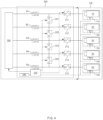
- FIG. 4 is a circuit diagram for describing an operation of a battery management apparatus, according to an embodiment disclosed herein.
- n batteries n is a natural number of 2 or greater
- the battery slot unit 100 may include a plurality of battery slots 110, 120, 130, 140, and 150.
- Each of the plurality of battery slots 110, 120, 130, 140, and 150 may include any one of the plurality of batteries 10, 20, 30, 40, and 50.
- the plurality of battery slots 110, 120, 130, 140, and 150 may respectively include temperature measurement sensors T1, T2, T3, T4, and T5.
- the plurality of temperature measurement sensors T1, T2, T3, T4, and T5 may measure temperatures of the plurality of batteries 10, 20, 30, 40, and 50.
- the plurality of temperature measurement sensors T1, T2, T3, T4, and T5 may include a plurality of thermistors.
- a thermistor may mean a resistor having a resistance sensitively changing with a temperature, and the thermistor may measure a temperature by using a resistance change of a ceramic material with respect to a temperature. The temperature of the thermistor may increase due to occurrence of a self-heating phenomenon when current is applied thereto.
- the controller 230 may obtain temperature information of the plurality of batteries 10, 20, 30, 40, and 50 from the plurality of temperature measurement sensors T1, T2, T3, T4, and T5 that measure the temperatures of the plurality of batteries 10, 20, 30, 40, and 50. For example, the controller 230 may determine, as the abnormal battery, the first battery 10 among the plurality of batteries 10, 20, 30, 40, and 50 for which an abnormal temperature is sensed.
- the controller 230 may determine the first battery 10 to be an abnormal battery.
- the controller 230 may determine the first battery 10 as an abnormal battery.
- the controller 230 may transmit a charge stop signal of the plurality of batteries 10, 20, 30, 40, and 50 to the charger 300.
- the controller 230 may calculate capacities of the first battery 10 and the second battery 20.
- the controller 230 may receive battery data through communication with a BMS for the first battery 10 and a BMS for the second battery 10.
- the battery data may include, for example, a voltage of the battery, a voltage of a battery cell of the battery, a fault signal, an internal temperature of the battery, etc.
- the controller 230 may calculate capacities of the first battery 10 and the second battery 20 based on the battery data of the first battery 10 and the second battery 20.
- the controller 230 may control operations of the plurality of first switches 210 and the plurality of second switches 220 by comparing the capacity of the first battery 10 with the capacity of the second battery 20.
- the controller 230 may discharge the first battery 10 until the capacity of the first battery 10 is equal to the capacity of the second battery 20.
- the capacity of the first battery 10 is 8000 mA
- a voltage of the first battery 10 is 60 V
- the capacity of the second battery 20 is 4000 mAh
- a voltage of the second battery 20 is 50 V
- the controller 230 may discharge the first battery 10 until the capacity of the first battery 10 is equal to the capacity of the second battery 20.
- the controller 230 may turn on, among the plurality of first switches 210, a first switch 211 for connecting the first battery 10 to a first resistor R1 connected to the first battery 10, and turn off the plurality of other first switches 212, 213, 214, and 215.
- the controller 230 may turn on at least any one second switch of the plurality of second switches 220 to adjust a distribution ratio of discharge current of the first battery 10 applied to the plurality of resistors R.
- the controller 230 may connect a first resistor R1, a second resistor R2, a third resistor R3, and a fourth resistor R4 among the plurality of resistors R in parallel to control a total resistance value of the first resistor R1, the second resistor R2, the third resistor R3, and the fourth resistor R4 connected in parallel to be 6 ohm.
- the controller 230 may turn on some second switches 221, 222 and 223 capable of connecting the first resistor R1, the second resistor R2, the third resistor R3, and the fourth resistor R4 in parallel among the plurality of second switches 220, and turn off a second switch 224 capable of connecting a fifth resistor R5 in parallel.
- the controller 230 may discharge the second battery 20 until the capacity of the second battery 20 is equal to the capacity of the first battery 10.
- the controller 230 may discharge the second battery 20 until the capacity of the second battery 20 is equal to the capacity of the first battery 10.
- the controller 230 may turn on, among the plurality of first switches 210, the first switch 212 for connecting the second battery 20 to a second resistor R2 connected to the second battery 20, and turn off the plurality of other first switches 211, 213, 214, and 215.
- the controller 230 may turn on at least any one second switch of the plurality of second switches 220 to adjust a distribution ratio of discharge current of the second battery 20 applied to the plurality of resistors R.
- the controller 230 may connect a first resistor R1, a second resistor R2, a third resistor R3, and a fourth resistor R4 among the plurality of resistors R in parallel to control a total resistance value of the first resistor R1, the second resistor 2, the third resistor R3, and the fourth resistor R4 connected in parallel to be 6 ohm.
- the controller 230 may turn on some second switches 221, 222 and 223 capable of connecting the first resistor R1, the second resistor R2, the third resistor R3, and the fourth resistor R4 in parallel among the plurality of second switches 220, and turn off a second switch 224 capable of connecting a fifth resistor R5 in parallel.
- the controller 230 may turn on, among the plurality of first switches 210, the first switch 211 for connecting the first battery 10 to the first resistor R1 connected to the first battery 10, turn on the first switch 212 for connecting the second battery 20 to the second resistor R2 connected to the second battery 20, and turn off the plurality of other first switches 213, 214, and 215.
- the controller 230 may turn on at least any one second switch of the plurality of second switches 220 to adjust a distribution ratio of discharge currents of the first battery 10 and the second battery 20 applied to the plurality of resistors R.
- the battery management apparatus may control a discharge rate and heating by using a plurality of resistors connected to one another in parallel.
- the battery management apparatus may forcedly discharge an abnormal battery and a nearby battery to prevent a chain accident from occurring on the nearby battery, thereby stably operating the battery swapping station.
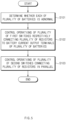
- FIG. 5 is a flowchart of an operating method of a battery management apparatus according to an embodiment disclosed herein.
- the operating method of the battery management apparatus may include operation S101 of determining whether each of a plurality of batteries is abnormal, operation S102 of controlling operations of a plurality of first switches for connecting a plurality of resistors respectively connected to the plurality of batteries to battery current output terminals of the plurality of batteries, based on whether each of the plurality of batteries is abnormal, and operation S103 of controlling operations of a plurality of second switches for connecting the plurality of resistors in parallel.
- the battery management apparatus 200 may be substantially the same as the battery management apparatus 200 described with reference to FIGS. 1 to 4 , and thus will be briefly described to avoid redundant description.
- the controller 230 may determine whether each of the plurality of batteries 10, 20, 30, 40, and 50 is abnormal.
- the controller 230 may determine any one of the plurality of batteries 10, 20, 30, 40, and 50 to be an abnormal battery.
- the controller 230 may determine the any one of the plurality of batteries 10, 20, 30, 40, and 50 to be an abnormal battery.
- the controller 230 may receive temperature information of the plurality of batteries 10, 20, 30, 40, and 50 from a plurality of temperature measurement sensors mounted in the battery slot unit 100, and may determine any one of the plurality of batteries 10, 20, 30, 40, and 50 to be an abnormal battery when a temperature of the any one of the plurality of batteries 10, 20, 30, 40, and 50 exceeds a threshold temperature based on the temperature information.
- the controller 230 may determine, as the abnormal battery, the first battery 10 among the plurality of batteries 10, 20, 30, 40, and 50 for which an abnormal temperature or an abnormality signal is sensed.
- the controller 230 may determine at least one second battery 20 related to the first battery 10 determined as the abnormal battery.
- the controller 230 may determine at least one second battery 20 adjacent to the first battery 10 based on a previously stored arrangement order of the plurality of batteries 10, 20, 30, 40, and 50.
- the controller 230 may control operations of the plurality of first switches 210, based on whether the plurality of batteries 10, 20, 30, 40, and 50 are abnormal.
- the controller 230 may control operations of the plurality of first switches 210 by comparing the capacity of the first battery 10 with the capacity of the second battery 20.
- the controller 230 may control operations of the plurality of first switches 210, based on whether the plurality of batteries 10, 20, 30, 40, and 50 are abnormal.
- the controller 230 may turn on at least any one second switch of the plurality of second switches 220 to adjust a distribution ratio of discharge current of the first battery 10 applied to the plurality of resistors R.
- the controller 230 may connect a first resistor R1, a second resistor R2, a third resistor R3, and a fourth resistor R4 among the plurality of resistors R in parallel to control a total resistance value of the first resistor R1, the second resistor R2, the third resistor R3, and the fourth resistor R4 connected in parallel to be 6 ohm.
- the controller 230 may turn on some second switches 221, 222 and 223 capable of connecting the first resistor R1, the second resistor R2, the third resistor R3, and the fourth resistor R4 in parallel among the plurality of second switches 220, and turn off a second switch 224 capable of connecting a fifth resistor R5 in parallel.
- FIG. 6 is a flowchart showing an operating method of a battery management apparatus, according to another embodiment disclosed herein.
- the operating method of the battery management apparatus may include operation S201 of determining whether each of a plurality of batteries is abnormal, operation S202 of stopping charge of all of the plurality of batteries, operation S203 of determining capacities of a first battery and a second battery, operation S204 of comparing the capacity of the first battery with the capacity of the second battery, operation S205 of discharging the first battery until the capacity of the first battery is equal to the capacity of the second battery, operation S206 of discharging the second battery until the capacity of the second battery is equal to the capacity of the first battery, and operation S207 of starting simultaneous discharge of the first battery and the second battery.
- the battery management apparatus 200 may be substantially the same as the battery management apparatus 200 described with reference to FIGS. 1 to 4 , and thus will be briefly described to avoid redundant description.
- the controller 230 may determine whether each of the plurality of batteries 10, 20, 30, 40, and 50 is abnormal.
- the controller 230 may determine, as the abnormal battery, the first battery 10 among the plurality of batteries 10, 20, 30, 40, and 50 for which an abnormal temperature or an abnormality signal is sensed. In operation S201, the controller 230 may determine at least one second battery 20 related to the first battery 10 determined as the abnormal battery. In operation S201, for example, the controller 230 may determine at least one second battery 20 adjacent to the first battery 10 based on a previously stored arrangement order of the plurality of batteries 10, 20, 30, 40, and 50.
- the controller 230 may stop charge of the plurality of batteries 10, 20, 30, 40, and 50. In operation S202, the controller 230 may transmit a charge stop signal for the first battery 10 determined as the abnormal battery and the second battery 20 adjacent to the first battery 10 to the charger 300.
- the controller 230 may calculate the capacities of the first battery 10 determined as the abnormal battery and the second battery 20.
- the controller 230 may receive battery data through communication with a BMS for the first battery 10 and a BMS for the second battery 10.
- the battery data may include, for example, a voltage of the battery, a voltage of a battery cell of the battery, a fault signal, an internal temperature of the battery, etc.
- the controller 230 may calculate capacities of the first battery 10 and the second battery 10 based on the battery data of the first battery 10 and the second battery 20.
- the controller 230 may compare the capacity of the first battery 10 with the capacity of the second battery 20.
- the controller 230 may control operations of the plurality of first switches 210 by comparing the capacity of the first battery 10 with the capacity of the second battery 20.
- the controller 230 may discharge the first battery 10 until the capacity of the first battery 10 is equal to the capacity of the second battery 20.
- the controller 230 may discharge the first battery 10 until the capacity of the first battery 10 is equal to the capacity of the second battery 20.
- the controller 230 may turn on, among the plurality of first switches 210, the first switch 211 for connecting the first battery 10 to the first resistor R1 connected to the first battery 10, and turn off the plurality of other first switches 212, 213, 214, and 215.
- the controller 230 may discharge the second battery 20 until the capacity of the second battery 20 is equal to the capacity of the first battery 10.
- the controller 230 may discharge the second battery 20 until the capacity of the second battery 20 is equal to the capacity of the first battery 10.
- the controller 230 may turn on, among the plurality of first switches 210, the first switch 212 for connecting the second battery 20 to the second resistor R2 connected to the second battery 20, and turn off the plurality of other first switches 211, 213, 214, and 215.
- the controller 230 may discharge the first battery 10 and the second battery 20 at the same time.
- the controller 230 may turn on, among the plurality of first switches 210, the first switch 211 for connecting the first battery 10 to the first resistor R1 connected to the first battery 10, turn on the first switch 212 for connecting the second battery 20 to the second resistor R2 connected to the second battery 20, and turn off the plurality of other first switches 213, 214, and 215.
- the controller 230 may turn on at least any one second switch of the plurality of second switches 220 to adjust a distribution ratio of discharge currents of the first battery 10 and the second battery 20 applied to the plurality of resistors R.
- FIG. 7 is a block diagram showing a hardware configuration of a computing system for performing an operating method of a battery management apparatus, according to an embodiment disclosed herein.
- a computing system 2000 may include an MCU 2100, a memory 2200, an input/output I/F 2300, and a communication I/F 2400.
- the MCU 2100 may be a processor that executes various programs (e.g., a battery capacity calculation program) stored in the memory 2200, processes various data including an SOC, an SOH, etc., of a plurality of battery cells through these programs, executes functions of the battery management apparatus 200 described above with reference to FIG. 1 , or executes the operating method of the battery management apparatus described with reference to FIG. 4 .
- various programs e.g., a battery capacity calculation program
- the memory 2200 may store various programs regarding SOH calculation of the battery cell, cell target determination, etc. Moreover, the memory 2200 may store various data such as SOC data, SOH data, etc., of each battery cell.
- the memory 2200 may be provided in plural, depending on a need.
- the memory 2200 may be volatile memory or non-volatile memory.
- RAM random access memory
- DRAM dynamic RAM
- SRAM static RAM
- ROM read only memory
- PROM programmable ROM
- EAROM electrically alterable ROM
- EPROM erasable PROM
- EEPROM electrically erasable PROM
- flash memory etc.
- the above-listed examples of the memory 220 are merely examples and are not limited thereto.
- the input/output I/F 2300 may provide an interface for transmitting and receiving data by connecting an input device (not shown) such as a keyboard, a mouse, a touch panel, etc., and an output device such as a display (not shown), etc., to the MCU 2100.
- an input device such as a keyboard, a mouse, a touch panel, etc.
- an output device such as a display (not shown), etc.
- the communication I/F 2300 which is a component capable of transmitting and receiving various data to and from a server, may be various devices capable of supporting wired or wireless communication.
- a program for SOH calculation of the battery cell or target determination or various data, etc. may be transmitted and received to and from a separately provided external server through the communication I/F 2300.
- an operating method of a battery management apparatus may be recorded in the memory 2200 and executed by the MCU 2100.
Landscapes
- Engineering & Computer Science (AREA)
- General Physics & Mathematics (AREA)
- Physics & Mathematics (AREA)
- Power Engineering (AREA)
- Chemical & Material Sciences (AREA)
- Electrochemistry (AREA)
- General Chemical & Material Sciences (AREA)
- Chemical Kinetics & Catalysis (AREA)
- Manufacturing & Machinery (AREA)
- Microelectronics & Electronic Packaging (AREA)
- Charge And Discharge Circuits For Batteries Or The Like (AREA)
- Secondary Cells (AREA)
- Tests Of Electric Status Of Batteries (AREA)
- Protection Of Static Devices (AREA)
Abstract
Description
- This application claims priority to and the benefit of
Korean Patent Application No. 10-2022-0122898 filed in the Korean Intellectual Property Office on September 27, 2022 - Embodiments disclosed herein relate to a battery management apparatus and an operating method thereof.
- Recently, research and development of secondary batteries have been actively performed. Secondary batteries, which are chargeable/dischargeable batteries, may include all of conventional nickel (Ni)/cadmium (Cd) batteries, Ni/metal hydride (MH) batteries, etc., and recent lithium-ion batteries. Among the secondary batteries, a lithium-ion battery has a much higher energy density than those of conventional Ni/Cd batteries, Ni/MH batteries, etc. Moreover, the lithium-ion battery may be manufactured to be small and lightweight, such that the lithium-ion battery has been used as a power source of mobile devices, and recently, a use range thereof has been extended to power sources for electric vehicles, attracting attention as next-generation energy storage media.
- To further increase the usability and portability of the lithium-ion battery, a battery swapping service has been provided. However, when some of the batteries in a battery swapping station catch fire, chain ignition may occur to nearby batteries, causing all batteries in the battery swapping station to burn out.
- A discharge rate of the igniting battery may be raised to prevent the chain ignition of the battery swapping station, but the discharge rate of the battery may be determined and fixed by a resistance value of a discharge resistor connected to the battery, such that the discharge resistor needs to be changed to adjust the discharge rate.
- Embodiments disclosed herein provide a battery management apparatus and an operating method thereof in which a discharge rate and/or heating of a battery may be controlled using a plurality of resistors connected to one another in parallel.
- Technical problems of the embodiments disclosed herein are not limited to the above-described technical problems, and other unmentioned technical problems would be clearly understood by one of ordinary skill in the art from the following description.
- A battery management apparatus according to an embodiment disclosed herein includes a plurality of resistors respectively connected to a plurality of batteries, a plurality of first switches configured to respectively connect the plurality of resistors to output terminals of the plurality of batteries, a plurality of second switches configured to connect the plurality of resistors in parallel, and a controller configured to determine whether each of the plurality of batteries is abnormal, and control operations of the plurality of first switches and the plurality of second switches based on whether each of the plurality of batteries is abnormal.
- In an embodiment, the plurality of resistors may be respectively connected to the plurality of batteries in parallel, and the plurality of second switches may be serially connected to one another.
- In an embodiment, the battery management apparatus may further include a communication unit configured to receive an abnormality signal of the plurality of batteries from a battery management system (BMS) for each of the plurality of batteries, in which the controller is further configured to determine a first battery for which an abnormality signal is sensed and at least one second battery related to the first battery among the plurality of batteries, based on the abnormality signal.
- In an embodiment, the controller may be further configured to obtain temperature information of the plurality of batteries from a plurality of temperature measurement sensors that measure temperatures of the plurality of batteries, and determine a first battery for which an abnormal temperature is sensed and at least one second battery related to the first battery among the plurality of batteries, based on the temperature information.
- In an embodiment, the controller may be further configured to determine the at least one second battery adjacent to the first battery based on an arrangement order of the plurality of batteries, when sensing an abnormal temperature or an abnormality signal of the first battery among the plurality of batteries.
- In an embodiment, the controller may be further configured to calculate a capacity of the first battery and a capacity of the at least one second battery and compare the capacity of the first battery with the capacity of the second battery to control operations of the plurality of first switches and the plurality of second switches.
- In an embodiment, when the capacity of the first battery exceeds the capacity of the at least one second battery, the controller may be further configured to turn on a first switch for connecting the first battery to a resistor connected to the first battery among the plurality of first switches and turn on at least any one second switch among the plurality of second switches.
- In an embodiment, when the capacity of the first battery is less than the capacity of the at least one second battery, the controller may be further configured to turn on a first switch for connecting the second battery to a resistor connected to the second battery among the plurality of first switches and turn on at least any one second switch among the plurality of second switches.
- An operating method of a battery management apparatus according to an embodiment disclosed herein includes determining whether each of the plurality of batteries is abnormal, controlling operations of a plurality of first switches for respectively connecting a plurality of resistors respectively connected to the plurality of batteries to battery current output terminals of the plurality of batteries, based on whether each of the plurality of batteries is abnormal, and controlling operations of a plurality of second switches connecting the plurality of resistors in parallel.
- In an embodiment, the determining of whether each of the plurality of batteries is abnormal may include receiving an abnormality signal of the plurality of batteries from a battery management system (BMS) for each of the plurality of batteries and determining a first battery for which an abnormality signal is sensed and at least one second battery related to the first battery among the plurality of batteries, based on the abnormality signal.
- In an embodiment, the determining of whether each of the plurality of batteries is abnormal may include obtaining temperature information of the plurality of batteries from a plurality of temperature measurement sensors that measure temperatures of the plurality of batteries and determining a first battery for which an abnormal temperature is sensed and at least one second battery related to the first battery among the plurality of batteries, based on the temperature information.
- In an embodiment, the determining of whether each of the plurality of batteries is abnormal may include determining the at least one second battery adjacent to the first battery based on an arrangement order of the plurality of batteries, when sensing an abnormal temperature or an abnormality signal of the first battery among the plurality of batteries.
- In an embodiment, the determining of whether each of the plurality of batteries is abnormal may include calculating a capacity of the first battery and a capacity of the at least one second battery and comparing the capacity of the first battery with the capacity of the second battery to control operations of the plurality of first switches and the plurality of second switches.
- In an embodiment, the controlling of the operations of a plurality of first switches for respectively connecting a plurality of resistors respectively connected to the plurality of batteries to battery current output terminals of the plurality of batteries, based on whether each of the plurality of batteries is abnormal may include, when the capacity of the first battery exceeds the capacity of the at least one second battery, turning on a first switch for connecting the first battery to a resistor connected to the first battery among the plurality of first switches, and the controlling of the operations of a plurality of second switches connecting the plurality of resistors in parallel may include turning on at least any one second switch among the plurality of second switches.
- In an embodiment, the controlling of the operations of a plurality of first switches for respectively connecting a plurality of resistors respectively connected to the plurality of batteries to battery current output terminals of the plurality of batteries, based on whether each of the plurality of batteries is abnormal may include, when the capacity of the first battery is less than the capacity of the at least one second battery, turning on a first switch for connecting the second battery to a resistor connected to the second battery among the plurality of first switches, and the controlling of the operations of a plurality of second switches connecting the plurality of resistors in parallel may include turning on at least any one second switch among the plurality of second switches.
- A battery management apparatus and an operating method thereof according to an embodiment disclosed herein may control a discharge rate and/or heating of a battery by using a plurality of resistors connected to one another in parallel.
- Moreover, the battery management system and the operating method thereof according to an embodiment disclosed herein may stably manage the lifespan of a battery.
-
-
FIG. 1 is a diagram conceptually showing a battery swapping station according to an embodiment disclosed herein. -
FIG. 2 is a diagram conceptually showing a battery swapping station according to another embodiment disclosed herein. -
FIG. 3 is a block diagram of a battery management apparatus according to an embodiment disclosed herein. -
FIG. 4 is a circuit diagram for describing an operation of a battery management apparatus, according to an embodiment disclosed herein. -
FIG. 5 is a flowchart of an operating method of a battery management apparatus according to an embodiment disclosed herein. -
FIG. 6 is a flowchart showing an operating method of a battery management apparatus, according to another embodiment disclosed herein. -
FIG. 7 is a block diagram showing a hardware configuration of a computing system for performing an operating method of a battery management apparatus, according to an embodiment disclosed herein. - Hereinafter, embodiments disclosed in this document will be described in detail with reference to the exemplary drawings. In adding reference numerals to components of each drawing, it should be noted that the same components are given the same reference numerals even though they are indicated in different drawings. In addition, in describing the embodiments disclosed in this document, when it is determined that a detailed description of a related known configuration or function interferes with the understanding of an embodiment disclosed in this document, the detailed description thereof will be omitted.
- To describe a component of an embodiment disclosed herein, terms such as first, second, A, B, (a), (b), etc., may be used. These terms are used merely for distinguishing one component from another component and do not limit the component to the essence, sequence, order, etc., of the component. The terms used herein, including technical and scientific terms, have the same meanings as terms that are generally understood by those skilled in the art, as long as the terms are not differently defined. Generally, the terms defined in a generally used dictionary should be interpreted as having the same meanings as the contextual meanings of the relevant technology and should not be interpreted as having ideal or exaggerated meanings unless they are clearly defined in the present application.
-
FIG. 1 is a diagram conceptually showing a battery swapping station according to an embodiment disclosed herein. - Referring to
FIG. 1 , a battery swapping system (BSS) 1000 may provide an overall management service for evaluation, measurement, charge, exchange, etc., of a battery, and in the present disclosure, a function of thebattery swapping system 1000 will be described based on a battery swapping service. Herein, the battery swapping service may mean a service that analyzes states of a plurality ofbatteries batteries other batteries battery swapping station 1000 may provide a user with a battery swapping service by collecting thebatteries batteries - Herein, the
batteries - Hereinbelow, a description will be made assuming that the plurality of
batteries FIG. 1 that the number ofbatteries - Depending on an embodiment, the
battery swapping station 1000 may be arranged in a service station where the battery swapping service is provided or in a space that is separate from the service station. - The
battery swapping station 1000 may analyze the states of the plurality ofbatteries batteries other batteries batteries battery swapping station 1000 may autonomously determine whether state analysis with respect to the plurality ofbatteries batteries battery swapping station 1000 may transmit to the cloud server, information that is a basis for determining whether swapping of a battery is required, and the cloud server may transmit to thebattery swapping station 1000, the information about whether swapping of the battery is required. -
FIG. 2 is a diagram conceptually showing a battery swapping station according to another embodiment disclosed herein. - Referring to
FIG. 2 , thebattery swapping station 1000 may include abattery slot unit 100, abattery management apparatus 200, and acharger 300. - The
battery slot unit 100 may accommodate the plurality ofbatteries battery slot unit 100 may include a plurality of battery slots that respectively accommodate the plurality of batteries connected. Thebattery slot unit 100 may be connected to thebattery management apparatus 200. The plurality ofbatteries battery slot unit 100 may be physically controlled based on a control signal of thebattery management apparatus 200. - The
battery management apparatus 200 may manage and/or control a state and/or an operation of the plurality ofbatteries battery management apparatus 200 may manage charge and/or discharge of the plurality ofbatteries - In addition, the
battery management apparatus 200 may monitor a voltage, a current, a temperature, etc., of each of the plurality ofbatteries battery management apparatus 200 may calculate parameters indicating the states of the plurality ofbatteries - The
battery management apparatus 200 may manage a state of charge (SoC) and/or a state of health (SoH) of the plurality ofbatteries battery management apparatus 200 may receive SoC information of each of the plurality ofbatteries batteries battery management apparatus 200 may obtain SoC information by directly calculating a remaining capacity rate for a battery of the battery without receiving the SoC information from the BMS for the battery. - The
charger 300 may charge each of the plurality ofbatteries battery management apparatus 200. Thecharger 300 may be supplied with power from an external utility power source to convert the power into a power form that may be received by the plurality ofbatteries batteries charger 300 may supply power until the SoCs of the plurality ofbatteries batteries - Hereinbelow, a configuration and an operation of the
battery management apparatus 200 will be described in more detail with reference toFIG. 3 . -
FIG. 3 is a block diagram of a battery management apparatus according to an embodiment disclosed herein. - Referring to
FIG. 3 , thebattery management apparatus 200 may include a plurality of resistors R, a plurality offirst switches 210, a plurality ofsecond switches 220, acontroller 230, and acommunication unit 240. - When any one of the plurality of
batteries battery management apparatus 200 ignites, thebattery management apparatus 200 may discharge an igniting battery or a nearby battery to remove fuel that is an energy source of the igniting battery or the nearby battery so as to suppress the spread of heat to the nearby battery or all the batteries. Thebattery management apparatus 200 may respectively connect the plurality of resistors R to the exterior of the plurality ofbatteries - Herein, the discharge rate of the battery may be determined by the resistance value of the plurality of resistors R, and the resistance value needs to be changed to adjust the discharge rate of the battery. Thus, the
battery management apparatus 200 may connect the plurality of resistors R in parallel and distribute discharge current to the plurality of resistors R connected in parallel to adjust the discharge current value, thus controlling the discharge rate. - The plurality of resistors R may be serially connected to the plurality of
batteries first switches 210 in series. More specifically, as the plurality offirst switches 210 are turned on, the plurality of resistors R may be respectively connected in series to the plurality ofbatteries first switches 210, thus discharging the batteries. - The plurality of resistors R may be connected to one another in parallel, and may be selectively connected in parallel based on the plurality of
first switches 210 respectively connected thereto being turned on/off. More specifically, as any one of the plurality offirst switches 210 respectively connected in series to the plurality of resistors R is selectively turned on, the resistors R connected to the plurality offirst switches 210 in the on state among the plurality of resistors R connected in parallel may be connected to one another in parallel. - That is, some of the plurality of resistors R may be selectively connected in parallel based on the plurality of
first switches 210 being on or off. Thus, resistance values of the plurality of resistors R may be changed, such that discharge rates of the plurality ofbatteries - The plurality of
first switches 210 may respectively connect the plurality of resistors R to output terminals of the plurality ofbatteries first switches 210 may be respectively connected to the plurality ofbatteries first switches 210 may be respectively connected to the plurality of resistors R in series. - Each of the plurality of
first switches 210 may receive a control signal from thecontroller 230, thus being turned on or off. - The plurality of
second switches 220 may be connected to the plurality of resistors R in parallel. The plurality ofsecond switches 220 may be serially connected to one another. Each of the plurality ofsecond switches 220 may receive a control signal from thecontroller 230, thus being turned on or off. - The
communication unit 240 may wiredly and/or wirelessly communicate with a BMS for each of the plurality ofbatteries communication unit 240 may communicate with a BMS for each of the plurality ofbatteries communication unit 240 may communicate with a BMS for each of the plurality ofbatteries - According to an embodiment, the
communication unit 240 may periodically communicate with a BMS for each of the plurality ofbatteries batteries communication unit 240 may transmit a communication signal to the BMS for any one of the plurality ofbatteries - According to an embodiment, the
communication unit 240 may receive an abnormality signal of the battery from the BMS for any one of the plurality ofbatteries - The
controller 230 may determine whether each of the plurality ofbatteries - According to an embodiment, when the
communication unit 240 does not receive a communication signal after an elapse of a specific period from a BMS for any one of the plurality ofbatteries batteries controller 230 may determine any one of the plurality ofbatteries - According to an embodiment, when the
communication unit 240 receives an abnormality signal from any one of the plurality ofbatteries controller 230 may determine the any one of the plurality ofbatteries - According to an embodiment, the
controller 230 may receive temperature information of the plurality ofbatteries battery slot unit 100, and may determine any one of the plurality ofbatteries batteries - For example, the
controller 230 may determine, as the abnormal battery, thefirst battery 10 among the plurality ofbatteries controller 230 may determine at least onesecond battery 20 related to thefirst battery 10 determined as the abnormal battery. For example, thecontroller 230 may determine at least onesecond battery 20 adjacent to thefirst battery 10 based on a previously stored arrangement order of the plurality ofbatteries - The
controller 230 may control operations of the plurality offirst switches 210 and the plurality ofsecond switches 220 based on whether the plurality ofbatteries -
FIG. 4 is a circuit diagram for describing an operation of a battery management apparatus, according to an embodiment disclosed herein. - Hereinbelow, an operation of the battery management apparatus will be described in detail with reference to
FIG. 4 . - While it is shown in
FIG. 4 that fivebatteries battery swapping system 1000, the scope of the present disclosure is not limited thereto and n batteries (n is a natural number of 2 or greater) for receiving the battery swapping service may be connected to thebattery swapping system 1000. - Referring to
FIG. 4 , thebattery slot unit 100 may include a plurality ofbattery slots battery slots batteries - The plurality of
battery slots batteries - According to an embodiment, the
controller 230 may obtain temperature information of the plurality ofbatteries batteries controller 230 may determine, as the abnormal battery, thefirst battery 10 among the plurality ofbatteries - In addition, for example, when the
communication unit 240 does not receive a communication signal after an elapse of a specific period from a BMS for thefirst battery 10 of the plurality ofbatteries first battery 10, thecontroller 230 may determine thefirst battery 10 to be an abnormal battery. - In addition, for example, when the
communication unit 240 receives an abnormality signal of the battery from thefirst battery 10 of the plurality ofbatteries controller 230 may determine thefirst battery 10 as an abnormal battery. - When determining that the
first battery 10 as an abnormal battery, thecontroller 230 may transmit a charge stop signal of the plurality ofbatteries charger 300. - The
controller 230 may calculate capacities of thefirst battery 10 and thesecond battery 20. Thecontroller 230 may receive battery data through communication with a BMS for thefirst battery 10 and a BMS for thesecond battery 10. Herein, the battery data may include, for example, a voltage of the battery, a voltage of a battery cell of the battery, a fault signal, an internal temperature of the battery, etc. Thecontroller 230 may calculate capacities of thefirst battery 10 and thesecond battery 20 based on the battery data of thefirst battery 10 and thesecond battery 20. - The
controller 230 may control operations of the plurality offirst switches 210 and the plurality ofsecond switches 220 by comparing the capacity of thefirst battery 10 with the capacity of thesecond battery 20. - According to an embodiment, when the capacity of the
first battery 10 exceeds the capacity of thesecond battery 20, thecontroller 230 may discharge thefirst battery 10 until the capacity of thefirst battery 10 is equal to the capacity of thesecond battery 20. For example, when the capacity of thefirst battery 10 is 8000 mA, a voltage of thefirst battery 10 is 60 V, the capacity of thesecond battery 20 is 4000 mAh, and a voltage of thesecond battery 20 is 50 V, thecontroller 230 may discharge thefirst battery 10 until the capacity of thefirst battery 10 is equal to the capacity of thesecond battery 20. Thecontroller 230 may turn on, among the plurality offirst switches 210, afirst switch 211 for connecting thefirst battery 10 to a first resistor R1 connected to thefirst battery 10, and turn off the plurality of otherfirst switches - The
controller 230 may turn on at least any one second switch of the plurality ofsecond switches 220 to adjust a distribution ratio of discharge current of thefirst battery 10 applied to the plurality of resistors R. - For example, when the discharge current of the
first battery 10 is 10 A and the voltage of thefirst battery 10 is 60 V, thecontroller 230 may turn on some of the plurality ofsecond switches 220 and turn off some others to control the plurality of resistor R values to be 60 V/10 A = 6 ohm. - For example, when a resistance value of each of the plurality of resistors R is 24 ohm, the
controller 230 may connect a first resistor R1, a second resistor R2, a third resistor R3, and a fourth resistor R4 among the plurality of resistors R in parallel to control a total resistance value of the first resistor R1, the second resistor R2, the third resistor R3, and the fourth resistor R4 connected in parallel to be 6 ohm. More specifically, thecontroller 230 may turn on somesecond switches second switches 220, and turn off asecond switch 224 capable of connecting a fifth resistor R5 in parallel. - According to an embodiment, when the capacity of the
first battery 10 is less than the capacity of thesecond battery 20, thecontroller 230 may discharge thesecond battery 20 until the capacity of thesecond battery 20 is equal to the capacity of thefirst battery 10. For example, when the capacity of thefirst battery 10 is 4000 mA, the voltage of thefirst battery 10 is 50 V, the capacity of thesecond battery 20 is 8000 mAh, and the voltage of thesecond battery 20 is 60 V, thecontroller 230 may discharge thesecond battery 20 until the capacity of thesecond battery 20 is equal to the capacity of thefirst battery 10. Thecontroller 230 may turn on, among the plurality offirst switches 210, thefirst switch 212 for connecting thesecond battery 20 to a second resistor R2 connected to thesecond battery 20, and turn off the plurality of otherfirst switches - The
controller 230 may turn on at least any one second switch of the plurality ofsecond switches 220 to adjust a distribution ratio of discharge current of thesecond battery 20 applied to the plurality of resistors R. - For example, when the discharge current of the
second battery 20 is 10 A and the voltage of thesecond battery 20 is 60 V, thecontroller 230 may turn on some of the plurality ofsecond switches 220 and turn off some others to control the plurality of resistor R values to be 60 V/10 A = 6 ohm. - For example, when a resistance value of each of the plurality of resistors R is 24 ohm, the
controller 230 may connect a first resistor R1, a second resistor R2, a third resistor R3, and a fourth resistor R4 among the plurality of resistors R in parallel to control a total resistance value of the first resistor R1, the second resistor 2, the third resistor R3, and the fourth resistor R4 connected in parallel to be 6 ohm. More specifically, thecontroller 230 may turn on somesecond switches second switches 220, and turn off asecond switch 224 capable of connecting a fifth resistor R5 in parallel. - According to an embodiment, when the capacity of the
first battery 10 is equal to the capacity of thesecond battery 20, thecontroller 230 may discharge thefirst battery 10 and thesecond battery 20 at the same time. - The
controller 230 may turn on, among the plurality offirst switches 210, thefirst switch 211 for connecting thefirst battery 10 to the first resistor R1 connected to thefirst battery 10, turn on thefirst switch 212 for connecting thesecond battery 20 to the second resistor R2 connected to thesecond battery 20, and turn off the plurality of otherfirst switches controller 230 may turn on at least any one second switch of the plurality ofsecond switches 220 to adjust a distribution ratio of discharge currents of thefirst battery 10 and thesecond battery 20 applied to the plurality of resistors R. - As described above, the battery management apparatus according to an embodiment disclosed herein may control a discharge rate and heating by using a plurality of resistors connected to one another in parallel.
- When a dangerous situation and abnormality occur in some batteries, the battery management apparatus may forcedly discharge an abnormal battery and a nearby battery to prevent a chain accident from occurring on the nearby battery, thereby stably operating the battery swapping station.
-
FIG. 5 is a flowchart of an operating method of a battery management apparatus according to an embodiment disclosed herein. - Referring to
FIG. 5 , the operating method of the battery management apparatus according to an embodiment disclosed herein may include operation S101 of determining whether each of a plurality of batteries is abnormal, operation S102 of controlling operations of a plurality of first switches for connecting a plurality of resistors respectively connected to the plurality of batteries to battery current output terminals of the plurality of batteries, based on whether each of the plurality of batteries is abnormal, and operation S103 of controlling operations of a plurality of second switches for connecting the plurality of resistors in parallel. - Hereinbelow, operations S101 through S103 will be described in detail with reference to
FIGS. 1 and4 . Thebattery management apparatus 200 may be substantially the same as thebattery management apparatus 200 described with reference toFIGS. 1 to 4 , and thus will be briefly described to avoid redundant description. - In operation S101, the
controller 230 may determine whether each of the plurality ofbatteries - In operation S101, when the
communication unit 240 does not receive a communication signal after an elapse of a specific period from a BMS for any one of the plurality ofbatteries batteries controller 230 may determine any one of the plurality ofbatteries - In operation S101, when the
communication unit 240 receives an abnormality signal from any one of the plurality ofbatteries controller 230 may determine the any one of the plurality ofbatteries - In operation S101, the
controller 230 may receive temperature information of the plurality ofbatteries battery slot unit 100, and may determine any one of the plurality ofbatteries batteries - In operation S101, the
controller 230 may determine, as the abnormal battery, thefirst battery 10 among the plurality ofbatteries controller 230 may determine at least onesecond battery 20 related to thefirst battery 10 determined as the abnormal battery. In operation S101, for example, thecontroller 230 may determine at least onesecond battery 20 adjacent to thefirst battery 10 based on a previously stored arrangement order of the plurality ofbatteries - In operation S102, the
controller 230 may control operations of the plurality offirst switches 210, based on whether the plurality ofbatteries - In operation S102, the
controller 230 may control operations of the plurality offirst switches 210 by comparing the capacity of thefirst battery 10 with the capacity of thesecond battery 20. - In operation S103, the
controller 230 may control operations of the plurality offirst switches 210, based on whether the plurality ofbatteries - In operation S103, the
controller 230 may turn on at least any one second switch of the plurality ofsecond switches 220 to adjust a distribution ratio of discharge current of thefirst battery 10 applied to the plurality of resistors R. - In operation S103, for example, when the discharge current of the
first battery 10 is 10 A and the voltage of thefirst battery 10 is 60 V, thecontroller 230 may turn on some of the plurality ofsecond switches 220 and turn off some others to control the plurality of resistor R values to be 60 V/10 A = 6 ohm. - In operation S103, for example, when a resistance value of each of the plurality of resistors R is 24 ohm, the
controller 230 may connect a first resistor R1, a second resistor R2, a third resistor R3, and a fourth resistor R4 among the plurality of resistors R in parallel to control a total resistance value of the first resistor R1, the second resistor R2, the third resistor R3, and the fourth resistor R4 connected in parallel to be 6 ohm. In operation S103, more specifically, thecontroller 230 may turn on somesecond switches second switches 220, and turn off asecond switch 224 capable of connecting a fifth resistor R5 in parallel. -
FIG. 6 is a flowchart showing an operating method of a battery management apparatus, according to another embodiment disclosed herein. - Referring to
FIG. 6 , the operating method of the battery management apparatus according to an embodiment disclosed herein may include operation S201 of determining whether each of a plurality of batteries is abnormal, operation S202 of stopping charge of all of the plurality of batteries, operation S203 of determining capacities of a first battery and a second battery, operation S204 of comparing the capacity of the first battery with the capacity of the second battery, operation S205 of discharging the first battery until the capacity of the first battery is equal to the capacity of the second battery, operation S206 of discharging the second battery until the capacity of the second battery is equal to the capacity of the first battery, and operation S207 of starting simultaneous discharge of the first battery and the second battery. - Hereinbelow, operations S201 through S207 will be described in detail with reference to
FIGS. 1 and4 . Thebattery management apparatus 200 may be substantially the same as thebattery management apparatus 200 described with reference toFIGS. 1 to 4 , and thus will be briefly described to avoid redundant description. - In operation S201, the
controller 230 may determine whether each of the plurality ofbatteries - In operation S201, the
controller 230 may determine, as the abnormal battery, thefirst battery 10 among the plurality ofbatteries controller 230 may determine at least onesecond battery 20 related to thefirst battery 10 determined as the abnormal battery. In operation S201, for example, thecontroller 230 may determine at least onesecond battery 20 adjacent to thefirst battery 10 based on a previously stored arrangement order of the plurality ofbatteries - In operation S202, the
controller 230 may stop charge of the plurality ofbatteries controller 230 may transmit a charge stop signal for thefirst battery 10 determined as the abnormal battery and thesecond battery 20 adjacent to thefirst battery 10 to thecharger 300. - In operation S203, the
controller 230 may calculate the capacities of thefirst battery 10 determined as the abnormal battery and thesecond battery 20. In operation S203, thecontroller 230 may receive battery data through communication with a BMS for thefirst battery 10 and a BMS for thesecond battery 10. Herein, the battery data may include, for example, a voltage of the battery, a voltage of a battery cell of the battery, a fault signal, an internal temperature of the battery, etc. In operation S203, thecontroller 230 may calculate capacities of thefirst battery 10 and thesecond battery 10 based on the battery data of thefirst battery 10 and thesecond battery 20. - In operation S204, the
controller 230 may compare the capacity of thefirst battery 10 with the capacity of thesecond battery 20. - In operation S205, the
controller 230 may control operations of the plurality offirst switches 210 by comparing the capacity of thefirst battery 10 with the capacity of thesecond battery 20. - In operation S205, when the capacity of the
first battery 10 exceeds the capacity of thesecond battery 20, thecontroller 230 may discharge thefirst battery 10 until the capacity of thefirst battery 10 is equal to the capacity of thesecond battery 20. In operation S205, for example, when the capacity of thefirst battery 10 is 8000 mA, a voltage of thefirst battery 10 is 60 V, the capacity of thesecond battery 20 is 4000 mAh, and a voltage of thesecond battery 20 is 50 V, thecontroller 230 may discharge thefirst battery 10 until the capacity of thefirst battery 10 is equal to the capacity of thesecond battery 20. In operation S102, thecontroller 230 may turn on, among the plurality offirst switches 210, thefirst switch 211 for connecting thefirst battery 10 to the first resistor R1 connected to thefirst battery 10, and turn off the plurality of otherfirst switches - In operation S206, when the capacity of the
first battery 10 is less than the capacity of thesecond battery 20, thecontroller 230 may discharge thesecond battery 20 until the capacity of thesecond battery 20 is equal to the capacity of thefirst battery 10. In operation S206, for example, when the capacity of thefirst battery 10 is 4000 mA, the voltage of thefirst battery 10 is 50 V, the capacity of thesecond battery 20 is 8000 mAh, and the voltage of thesecond battery 20 is 60 V, thecontroller 230 may discharge thesecond battery 20 until the capacity of thesecond battery 20 is equal to the capacity of thefirst battery 10. In operation S206, thecontroller 230 may turn on, among the plurality offirst switches 210, thefirst switch 212 for connecting thesecond battery 20 to the second resistor R2 connected to thesecond battery 20, and turn off the plurality of otherfirst switches - In operation S207, when the capacity of the
first battery 10 is equal to the capacity of thesecond battery 20, thecontroller 230 may discharge thefirst battery 10 and thesecond battery 20 at the same time. - In operation S207, the
controller 230 may turn on, among the plurality offirst switches 210, thefirst switch 211 for connecting thefirst battery 10 to the first resistor R1 connected to thefirst battery 10, turn on thefirst switch 212 for connecting thesecond battery 20 to the second resistor R2 connected to thesecond battery 20, and turn off the plurality of otherfirst switches controller 230 may turn on at least any one second switch of the plurality ofsecond switches 220 to adjust a distribution ratio of discharge currents of thefirst battery 10 and thesecond battery 20 applied to the plurality of resistors R. -
FIG. 7 is a block diagram showing a hardware configuration of a computing system for performing an operating method of a battery management apparatus, according to an embodiment disclosed herein. - Referring to
FIG. 7 , acomputing system 2000 according to an embodiment disclosed herein may include anMCU 2100, amemory 2200, an input/output I/F 2300, and a communication I/F 2400. - The
MCU 2100 may be a processor that executes various programs (e.g., a battery capacity calculation program) stored in thememory 2200, processes various data including an SOC, an SOH, etc., of a plurality of battery cells through these programs, executes functions of thebattery management apparatus 200 described above with reference toFIG. 1 , or executes the operating method of the battery management apparatus described with reference toFIG. 4 . - The
memory 2200 may store various programs regarding SOH calculation of the battery cell, cell target determination, etc. Moreover, thememory 2200 may store various data such as SOC data, SOH data, etc., of each battery cell. - The
memory 2200 may be provided in plural, depending on a need. Thememory 2200 may be volatile memory or non-volatile memory. For thememory 2200 as the volatile memory, random access memory (RAM), dynamic RAM (DRAM), static RAM (SRAM), etc., may be used. For thememory 2200 as the nonvolatile memory, read only memory (ROM), programmable ROM (PROM), electrically alterable ROM (EAROM), erasable PROM (EPROM), electrically erasable PROM (EEPROM), flash memory, etc., may be used. The above-listed examples of thememory 220 are merely examples and are not limited thereto. - The input/output I/
F 2300 may provide an interface for transmitting and receiving data by connecting an input device (not shown) such as a keyboard, a mouse, a touch panel, etc., and an output device such as a display (not shown), etc., to theMCU 2100. - The communication I/
F 2300, which is a component capable of transmitting and receiving various data to and from a server, may be various devices capable of supporting wired or wireless communication. For example, a program for SOH calculation of the battery cell or target determination or various data, etc., may be transmitted and received to and from a separately provided external server through the communication I/F 2300. - As such, an operating method of a battery management apparatus according to an embodiment disclosed herein may be recorded in the
memory 2200 and executed by theMCU 2100. - The above description is merely illustrative of the technical idea of the present disclosure, and various modifications and variations will be possible without departing from the essential characteristics of embodiments of the present disclosure by those of ordinary skill in the art to which the embodiments disclosed herein pertains.
- Therefore, the embodiments disclosed herein are intended for description rather than limitation of the technical spirit of the embodiments disclosed herein and the scope of the technical spirit of the present disclosure is not limited by these embodiments disclosed herein. The protection scope of the technical spirit disclosed herein should be interpreted by the following claims, and all technical spirits within the same range should be understood to be included in the range of the present disclosure.
-
- 10, 20, 30, 40, 50: Plurality of Batteries
- 1000: Battery Swapping Station
- 100: Battery slot unit
- 110, 120, 130, 140: Plurality of Battery Slots
- T1, T2, T3, T4, T5: Plurality of Temperature Measurement Sensors
- 200: Battery Management Apparatus
- R1: First Resistor
- R2: Second Resistor
- R3: Third Resistor
- R4: Fourth Resistor
- R5: Fifth Resistor
- 211, 212, 213, 214, 215: Plurality of First Switches
- 221, 222, 223, 224: Plurality of Second Switches
- 230: Controller
- 240: Communication Unit
- 300: Charger
- 2000: Computing System
- 2100: MCU
- 2200: Memory
- 2300: Input/Output I/F
- 2400: Communication I/F
Claims (15)
- A battery management apparatus comprising:a plurality of resistors respectively connected to a plurality of batteries;a plurality of first switches configured to respectively connect the plurality of resistors to output terminals of the plurality of batteries;a plurality of second switches configured to connect the plurality of resistors in parallel; anda controller configured to determine whether each of the plurality of batteries is abnormal, and control operations of the plurality of first switches and the plurality of second switches based on whether each of the plurality of batteries is abnormal.
- The battery management apparatus of claim 1, wherein the plurality of resistors are respectively connected to the plurality of batteries in series, and
the plurality of second switches are serially connected to one another. - The battery management apparatus of claim 2, further comprising a communication unit configured to receive an abnormality signal of the plurality of batteries from a battery management system (BMS) for each of the plurality of batteries,
wherein the controller is further configured to determine a first battery for which an abnormality signal is sensed and at least one second battery related to the first battery among the plurality of batteries, based on the abnormality signal. - The battery management apparatus of claim 3, wherein the controller is further configured to obtain temperature information of the plurality of batteries from a plurality of temperature measurement sensors that measure temperatures of the plurality of batteries, and determine a first battery for which an abnormal temperature is sensed and at least one second battery related to the first battery among the plurality of batteries, based on the temperature information.
- The battery management apparatus of claim 4, wherein the controller is further configured to determine the at least one second battery adjacent to the first battery based on an arrangement order of the plurality of batteries, when sensing an abnormal temperature or an abnormality signal of the first battery among the plurality of batteries.
- The battery management apparatus of claim 4, wherein the controller is further configured to calculate a capacity of the first battery and a capacity of the at least one second battery and compare the capacity of the first battery with the capacity of the second battery to control operations of the plurality of first switches and the plurality of second switches.
- The battery management apparatus of claim 6, wherein, when the capacity of the first battery exceeds the capacity of the at least one second battery, the controller is further configured to turn on a first switch for connecting the first battery to a resistor connected to the first battery among the plurality of first switches and turn on at least any one second switch among the plurality of second switches.
- The battery management apparatus of claim 6, wherein, when the capacity of the first battery is less than the capacity of the at least one second battery, the controller is further configured to turn on a first switch for connecting the second battery to a resistor connected to the second battery among the plurality of first switches and turn on at least any one second switch among the plurality of second switches.
- An operating method of a battery management apparatus, the operating method comprising:determining whether each of the plurality of batteries is abnormal;controlling operations of a plurality of first switches for respectively connecting a plurality of resistors respectively connected to the plurality of batteries to battery current output terminals of the plurality of batteries, based on whether each of the plurality of batteries is abnormal; andcontrolling operations of a plurality of second switches connecting the plurality of resistors in parallel.
- The operating method of claim 9, wherein the determining of whether each of the plurality of batteries is abnormal comprises:receiving an abnormality signal of the plurality of batteries from a battery management system (BMS) for each of the plurality of batteries; anddetermining a first battery for which an abnormality signal is sensed and at least one second battery related to the first battery among the plurality of batteries, based on the abnormality signal.
- The operating method of claim 10, wherein the determining of whether each of the plurality of batteries is abnormal comprises:obtaining temperature information of the plurality of batteries from a plurality of temperature measurement sensors that measure temperatures of the plurality of batteries; anddetermining a first battery for which an abnormal temperature is sensed and at least one second battery related to the first battery among the plurality of batteries, based on the temperature information.
- The operating method of claim 11, wherein the determining of whether each of the plurality of batteries is abnormal comprises determining the at least one second battery adjacent to the first battery based on an arrangement order of the plurality of batteries, when sensing an abnormal temperature or an abnormality signal of the first battery among the plurality of batteries.
- The operating method of claim 12, wherein the determining of whether each of the plurality of batteries is abnormal comprises calculating a capacity of the first battery and a capacity of the at least one second battery and comparing the capacity of the first battery with the capacity of the second battery to control operations of the plurality of first switches and the plurality of second switches.
- The operating method of claim 13, wherein the controlling of the operations of a plurality of first switches for respectively connecting a plurality of resistors respectively connected to the plurality of batteries to battery current output terminals of the plurality of batteries, based on whether each of the plurality of batteries is abnormal comprises, when the capacity of the first battery exceeds the capacity of the at least one second battery, turning on a first switch for connecting the first battery to a resistor connected to the first battery among the plurality of first switches, and
the controlling of the operations of a plurality of second switches connecting the plurality of resistors in parallel comprises turning on at least any one second switch among the plurality of second switches. - The operating method of claim 13, wherein the controlling of the operations of a plurality of first switches for respectively connecting a plurality of resistors respectively connected to the plurality of batteries to battery current output terminals of the plurality of batteries, based on whether each of the plurality of batteries is abnormal comprises, when the capacity of the first battery is less than the capacity of the at least one second battery, turning on a first switch for connecting the second battery to a resistor connected to the second battery among the plurality of first switches, and
the controlling of the operations of a plurality of second switches connecting the plurality of resistors in parallel comprises turning on at least any one second switch among the plurality of second switches.
Applications Claiming Priority (2)
| Application Number | Priority Date | Filing Date | Title |
|---|---|---|---|
| KR1020220122898A KR102888916B1 (en) | 2022-09-27 | 2022-09-27 | Apparatus for managing battery and operating method of the same |
| PCT/KR2023/011775 WO2024071662A1 (en) | 2022-09-27 | 2023-08-09 | Battery management apparatus and operating method thereof |
Publications (2)
| Publication Number | Publication Date |
|---|---|
| EP4549971A1 true EP4549971A1 (en) | 2025-05-07 |
| EP4549971A4 EP4549971A4 (en) | 2025-10-15 |
Family
ID=90478342
Family Applications (1)
| Application Number | Title | Priority Date | Filing Date |
|---|---|---|---|
| EP23872785.3A Pending EP4549971A4 (en) | 2022-09-27 | 2023-08-09 | BATTERY MANAGEMENT APPARATUS AND ITS OPERATING METHOD |
Country Status (6)
| Country | Link |
|---|---|
| US (1) | US20260025013A1 (en) |
| EP (1) | EP4549971A4 (en) |
| JP (1) | JP2025528846A (en) |
| KR (1) | KR102888916B1 (en) |
| CN (1) | CN119731548A (en) |
| WO (1) | WO2024071662A1 (en) |
Family Cites Families (11)
| Publication number | Priority date | Publication date | Assignee | Title |
|---|---|---|---|---|
| JP3878602B2 (en) * | 2003-12-25 | 2007-02-07 | 日本無線株式会社 | Charge control device for large capacity capacitor, discharge control device for large capacity capacitor, charge control method for large capacity capacitor, and discharge control method for large capacity capacitor |
| JP4195026B2 (en) * | 2005-08-24 | 2008-12-10 | 矢崎総業株式会社 | Battery charge state adjustment device |
| KR100912350B1 (en) * | 2006-07-27 | 2009-08-14 | 주식회사 엘지화학 | Method and device for heating battery device |
| US8350528B2 (en) * | 2009-02-04 | 2013-01-08 | Samsung Sdi Co., Ltd. | Battery pack and balancing method of battery cells |
| KR20120059247A (en) * | 2010-11-30 | 2012-06-08 | 현대자동차주식회사 | System for cell balance control of battery pack and method thereof |
| CN105190987B (en) * | 2013-05-08 | 2018-06-22 | 株式会社Lg化学 | Battery warm-up system and battery warm-up method using the same |
| KR101610925B1 (en) * | 2014-12-12 | 2016-04-08 | 현대오트론 주식회사 | Apparatus and method for discharging battery |
| KR102192188B1 (en) * | 2017-04-17 | 2020-12-16 | 주식회사 엘지화학 | Apparatus and method for preventing overcharge |
| KR102349705B1 (en) * | 2017-06-22 | 2022-01-10 | 주식회사 엘지에너지솔루션 | Battery cell balancing circuit and apparatus and method for balancing of a battery cell for using the same |
| JP2021036734A (en) * | 2017-10-06 | 2021-03-04 | 株式会社村田製作所 | Batteries |
| CN107769330B (en) * | 2017-11-22 | 2019-07-16 | 集美大学 | A kind of energy management and control method of Electrical Propulsion Ship |
-
2022
- 2022-09-27 KR KR1020220122898A patent/KR102888916B1/en active Active
-
2023
- 2023-08-09 EP EP23872785.3A patent/EP4549971A4/en active Pending
- 2023-08-09 US US18/998,361 patent/US20260025013A1/en active Pending
- 2023-08-09 CN CN202380059960.2A patent/CN119731548A/en active Pending
- 2023-08-09 JP JP2025508794A patent/JP2025528846A/en active Pending
- 2023-08-09 WO PCT/KR2023/011775 patent/WO2024071662A1/en not_active Ceased
Also Published As
| Publication number | Publication date |
|---|---|
| CN119731548A (en) | 2025-03-28 |
| WO2024071662A1 (en) | 2024-04-04 |
| KR20240043605A (en) | 2024-04-03 |
| KR102888916B1 (en) | 2025-11-20 |
| JP2025528846A (en) | 2025-09-02 |
| US20260025013A1 (en) | 2026-01-22 |
| EP4549971A4 (en) | 2025-10-15 |
Similar Documents
| Publication | Publication Date | Title |
|---|---|---|
| US10873201B2 (en) | Battery management apparatus and method for protecting a lithium iron phosphate cell from over-voltage using the same | |
| US12449485B2 (en) | Battery management apparatus and method | |
| EP4394407B1 (en) | Battery management device and operation method thereof | |
| KR20230108663A (en) | Battery depth of charge calculating apparatus and operating method of the same | |
| KR20230055178A (en) | Apparatus and method for checking current sensor abnormality in battery | |
| US20230344248A1 (en) | Battery management apparatus and operating method thereof | |
| US20260025013A1 (en) | Battery management apparatus and operating method thereof | |
| EP4365613A1 (en) | Battery pack and operating method thereof | |
| KR102864746B1 (en) | Battery management apparatus and operating method of the same | |
| JP7472430B2 (en) | Battery management device and method, battery management system | |
| US20240356346A1 (en) | Battery management apparatus and operating method thereof | |
| EP4325232A1 (en) | Battery management device and operating method therefor | |
| EP4635790A1 (en) | Apparatus for providing battery life information and operating method thereof | |
| US20250170917A1 (en) | Battery Management Apparatus and Operating Method Thereof | |
| EP4661158A1 (en) | Battery pack and diagnosis method therefor | |
| US20260086159A1 (en) | Battery Management Apparatus and Operating Method Thereof | |
| EP4697046A1 (en) | Battery diagnosis apparatus and operating method thereof | |
| KR20250010934A (en) | Battery management apparatus and operating method of the same | |
| KR20250014601A (en) | Battery management apparatus and operating method of the same | |
| KR20250059009A (en) | Battery management system and operating method thereof | |
| KR20240093233A (en) | Battery management apparatus and operating method of the same | |
| KR20250043907A (en) | Battery diagnosis apparatus and operating method of the same | |
| JPH11339857A (en) | Discharge control device for secondary battery |
Legal Events
| Date | Code | Title | Description |
|---|---|---|---|
| STAA | Information on the status of an ep patent application or granted ep patent |
Free format text: STATUS: THE INTERNATIONAL PUBLICATION HAS BEEN MADE |
|
| PUAI | Public reference made under article 153(3) epc to a published international application that has entered the european phase |
Free format text: ORIGINAL CODE: 0009012 |
|
| STAA | Information on the status of an ep patent application or granted ep patent |
Free format text: STATUS: REQUEST FOR EXAMINATION WAS MADE |
|
| 17P | Request for examination filed |
Effective date: 20250129 |
|
| AK | Designated contracting states |
Kind code of ref document: A1 Designated state(s): AL AT BE BG CH CY CZ DE DK EE ES FI FR GB GR HR HU IE IS IT LI LT LU LV MC ME MK MT NL NO PL PT RO RS SE SI SK SM TR |
|
| A4 | Supplementary search report drawn up and despatched |
Effective date: 20250911 |
|
| RIC1 | Information provided on ipc code assigned before grant |
Ipc: G01R 31/392 20190101AFI20250905BHEP Ipc: G01R 31/371 20190101ALI20250905BHEP Ipc: G01R 31/382 20190101ALI20250905BHEP Ipc: G01R 31/396 20190101ALI20250905BHEP Ipc: H01M 10/48 20060101ALI20250905BHEP Ipc: H01M 10/052 20100101ALI20250905BHEP |
|
| DAV | Request for validation of the european patent (deleted) | ||
| DAX | Request for extension of the european patent (deleted) |