EP4549954A1 - Connector and connection structure for microfluidic device - Google Patents
Connector and connection structure for microfluidic device Download PDFInfo
- Publication number
- EP4549954A1 EP4549954A1 EP23830832.4A EP23830832A EP4549954A1 EP 4549954 A1 EP4549954 A1 EP 4549954A1 EP 23830832 A EP23830832 A EP 23830832A EP 4549954 A1 EP4549954 A1 EP 4549954A1
- Authority
- EP
- European Patent Office
- Prior art keywords
- connector
- fluid device
- holder
- micro
- tube
- Prior art date
- Legal status (The legal status is an assumption and is not a legal conclusion. Google has not performed a legal analysis and makes no representation as to the accuracy of the status listed.)
- Pending
Links
Images
Classifications
-
- B—PERFORMING OPERATIONS; TRANSPORTING
- B01—PHYSICAL OR CHEMICAL PROCESSES OR APPARATUS IN GENERAL
- B01L—CHEMICAL OR PHYSICAL LABORATORY APPARATUS FOR GENERAL USE
- B01L3/00—Containers or dishes for laboratory use, e.g. laboratory glassware; Droppers
- B01L3/56—Labware specially adapted for transferring fluids
- B01L3/563—Joints or fittings; Separable fluid transfer means to transfer fluids between at least two containers, e.g. connectors
-
- F—MECHANICAL ENGINEERING; LIGHTING; HEATING; WEAPONS; BLASTING
- F16—ENGINEERING ELEMENTS AND UNITS; GENERAL MEASURES FOR PRODUCING AND MAINTAINING EFFECTIVE FUNCTIONING OF MACHINES OR INSTALLATIONS; THERMAL INSULATION IN GENERAL
- F16L—PIPES; JOINTS OR FITTINGS FOR PIPES; SUPPORTS FOR PIPES, CABLES OR PROTECTIVE TUBING; MEANS FOR THERMAL INSULATION IN GENERAL
- F16L21/00—Joints with sleeve or socket
- F16L21/02—Joints with sleeve or socket with elastic sealing rings between pipe and sleeve or between pipe and socket, e.g. with rolling or other prefabricated profiled rings
- F16L21/03—Joints with sleeve or socket with elastic sealing rings between pipe and sleeve or between pipe and socket, e.g. with rolling or other prefabricated profiled rings placed in the socket before connection
-
- B—PERFORMING OPERATIONS; TRANSPORTING
- B01—PHYSICAL OR CHEMICAL PROCESSES OR APPARATUS IN GENERAL
- B01L—CHEMICAL OR PHYSICAL LABORATORY APPARATUS FOR GENERAL USE
- B01L3/00—Containers or dishes for laboratory use, e.g. laboratory glassware; Droppers
- B01L3/50—Containers for the purpose of retaining a material to be analysed, e.g. test tubes
- B01L3/502—Containers for the purpose of retaining a material to be analysed, e.g. test tubes with fluid transport, e.g. in multi-compartment structures
- B01L3/5027—Containers for the purpose of retaining a material to be analysed, e.g. test tubes with fluid transport, e.g. in multi-compartment structures by integrated microfluidic structures, i.e. dimensions of channels and chambers are such that surface tension forces are important, e.g. lab-on-a-chip
- B01L3/502715—Containers for the purpose of retaining a material to be analysed, e.g. test tubes with fluid transport, e.g. in multi-compartment structures by integrated microfluidic structures, i.e. dimensions of channels and chambers are such that surface tension forces are important, e.g. lab-on-a-chip characterised by interfacing components, e.g. fluidic, electrical, optical or mechanical interfaces
-
- B—PERFORMING OPERATIONS; TRANSPORTING
- B01—PHYSICAL OR CHEMICAL PROCESSES OR APPARATUS IN GENERAL
- B01L—CHEMICAL OR PHYSICAL LABORATORY APPARATUS FOR GENERAL USE
- B01L3/00—Containers or dishes for laboratory use, e.g. laboratory glassware; Droppers
- B01L3/56—Labware specially adapted for transferring fluids
- B01L3/565—Seals
-
- B—PERFORMING OPERATIONS; TRANSPORTING
- B01—PHYSICAL OR CHEMICAL PROCESSES OR APPARATUS IN GENERAL
- B01L—CHEMICAL OR PHYSICAL LABORATORY APPARATUS FOR GENERAL USE
- B01L2200/00—Solutions for specific problems relating to chemical or physical laboratory apparatus
- B01L2200/02—Adapting objects or devices to another
- B01L2200/026—Fluid interfacing between devices or objects, e.g. connectors, inlet details
- B01L2200/027—Fluid interfacing between devices or objects, e.g. connectors, inlet details for microfluidic devices
-
- B—PERFORMING OPERATIONS; TRANSPORTING
- B01—PHYSICAL OR CHEMICAL PROCESSES OR APPARATUS IN GENERAL
- B01L—CHEMICAL OR PHYSICAL LABORATORY APPARATUS FOR GENERAL USE
- B01L2200/00—Solutions for specific problems relating to chemical or physical laboratory apparatus
- B01L2200/06—Fluid handling related problems
- B01L2200/0689—Sealing
-
- B—PERFORMING OPERATIONS; TRANSPORTING
- B01—PHYSICAL OR CHEMICAL PROCESSES OR APPARATUS IN GENERAL
- B01L—CHEMICAL OR PHYSICAL LABORATORY APPARATUS FOR GENERAL USE
- B01L2300/00—Additional constructional details
- B01L2300/08—Geometry, shape and general structure
- B01L2300/0809—Geometry, shape and general structure rectangular shaped
-
- B—PERFORMING OPERATIONS; TRANSPORTING
- B01—PHYSICAL OR CHEMICAL PROCESSES OR APPARATUS IN GENERAL
- B01L—CHEMICAL OR PHYSICAL LABORATORY APPARATUS FOR GENERAL USE
- B01L2300/00—Additional constructional details
- B01L2300/08—Geometry, shape and general structure
- B01L2300/0809—Geometry, shape and general structure rectangular shaped
- B01L2300/0816—Cards, e.g. flat sample carriers usually with flow in two horizontal directions
-
- B—PERFORMING OPERATIONS; TRANSPORTING
- B01—PHYSICAL OR CHEMICAL PROCESSES OR APPARATUS IN GENERAL
- B01L—CHEMICAL OR PHYSICAL LABORATORY APPARATUS FOR GENERAL USE
- B01L2300/00—Additional constructional details
- B01L2300/08—Geometry, shape and general structure
- B01L2300/0832—Geometry, shape and general structure cylindrical, tube shaped
- B01L2300/0838—Capillaries
-
- B—PERFORMING OPERATIONS; TRANSPORTING
- B01—PHYSICAL OR CHEMICAL PROCESSES OR APPARATUS IN GENERAL
- B01L—CHEMICAL OR PHYSICAL LABORATORY APPARATUS FOR GENERAL USE
- B01L2300/00—Additional constructional details
- B01L2300/12—Specific details about materials
- B01L2300/123—Flexible; Elastomeric
-
- B—PERFORMING OPERATIONS; TRANSPORTING
- B01—PHYSICAL OR CHEMICAL PROCESSES OR APPARATUS IN GENERAL
- B01L—CHEMICAL OR PHYSICAL LABORATORY APPARATUS FOR GENERAL USE
- B01L2400/00—Moving or stopping fluids
- B01L2400/04—Moving fluids with specific forces or mechanical means
- B01L2400/0475—Moving fluids with specific forces or mechanical means specific mechanical means and fluid pressure
- B01L2400/0487—Moving fluids with specific forces or mechanical means specific mechanical means and fluid pressure fluid pressure, pneumatics
-
- C—CHEMISTRY; METALLURGY
- C12—BIOCHEMISTRY; BEER; SPIRITS; WINE; VINEGAR; MICROBIOLOGY; ENZYMOLOGY; MUTATION OR GENETIC ENGINEERING
- C12M—APPARATUS FOR ENZYMOLOGY OR MICROBIOLOGY; APPARATUS FOR CULTURING MICROORGANISMS FOR PRODUCING BIOMASS, FOR GROWING CELLS OR FOR OBTAINING FERMENTATION OR METABOLIC PRODUCTS, i.e. BIOREACTORS OR FERMENTERS
- C12M23/00—Constructional details, e.g. recesses, hinges
- C12M23/02—Form or structure of the vessel
- C12M23/16—Microfluidic devices; Capillary tubes
Definitions
- the present invention relates to a connector and a connection structure for a micro fluid device, and more particularly, to a connector interposed between a tube for supplying a fluid to a micro flow path formed inside a micro fluid device and a micro fluid device, and a connection structure for a micro fluid device using the connector.
- a micro fluid device for forming a fine flow path called a micro flow path having an flow path diameter of several micrometers to several hundred micrometers inside a resinous material or a glass material and performing various operations and processes such as separating, concentrating, reacting, and analyzing while flowing various fluids, including liquids such as a culture solution or a reaction solution, or a powder, through the micro flow path, on a microscale, by applying a semiconductor microfabrication technique or the like.
- a flow of blood or the like in a blood vessel can be reproduced in a micro flow path, or a biological experiment such as a cell culture or a tissue culture, a medical inspection, or the like can be performed in three dimensions and with a flow of a fluid, compared to the conventional method using a petri dish or the like.
- a supply operation for example, a liquid supply operation
- a fluid such as a culture solution to a fine micro flow path
- a method is known in which a micro pipette equipped with a pipette chip is used to inject a predetermined amount of fluid into a micro flow path.
- a connector formed of a resin material or the like may be interposed between the tube and the micro fluid device (for example, refer to Patent Document 1).
- a connector configured in a so-called "set screw" shape in which a tube insertion hole that passes through the central part and into which a tube can be inserted is provided, and a male screw is formed on one end side of the connector, is known.
- a device holder that supports the micro fluid device to which the connector is connected is provided with a connector receiving part in which a female screw that can be screwed with a male screw part of the connector is formed, and the connector receiving part and the flow path opening of the micro flow path of the fluid device are formed in communication.
- a fluid such as a culture solution supplied from a tube made of resin through a fluid supply unit can be supplied through a supply port to a space inside a micro flow path formed inside the micro fluid device through a connector, and various operations and processes such as culturing of cells and the like can be performed by using fluids supplied into the micro flow path and flowing therethrough.
- the fluid that has passed through the micro flow path is discharged from the other flow path opening (discharge port side) of the micro fluid path to the outside of the micro fluid device.
- a connector connected to the tube is interposed in the flow path opening on the discharge side in the same way as the supply side, and the fluid is discharged while the leakage of the fluid is prevented between the micro fluid device and the tube.
- the connector and the connection structure of the micro fluid device described above may cause the following problems.
- the connector in which the tube is connected needs to be screwed to the connector receiving part, and depending on the degree of fastening of the connector to the connector receiving part (degree of screwing), a part of the tube insertion hole inside the connector may be blocked, or a part of the micro flow path connected to the connector receiving part may be blocked. Therefore, it is necessary to pay sufficient attention to the mounting operation of the connector to the connector receiving part, and mounting such a connector may take time and may impose an excessive work load on the operator, such as troublesome work and complicated adjustment.
- an object of the present invention is to provide a connector formed with a relatively simple structure for connecting a tube for supplying or discharging fluid to a fluid device to supply a fluid to a micro flow path, and capable of easily performing a connecting operation between a tube and a micro fluid device, and a connection structure for a micro fluid device using the connector.
- a connector and a connection structure for a micro fluid device that solve the above problems are provided below.
- the connector of the present invention is formed in a relatively simple structure, and the connection between the tube and the micro fluid device can be performed in a simple and short time, and the connection structure for the micro fluid device of the present invention can be constructed.
- the connection structure for the micro fluid device using the connector of the present invention can reduce the time required for various operations such as culture experiments and preparation for processing, reduce the number of work steps, and eliminate the complexity of the work process.
- a connector and a connection structure for a micro fluid device (hereinafter, simply referred to as a "device connection structure") of the present invention will be described with reference to the drawings.
- the connector and the device connection structure of the present invention are not limited to those shown below, and various design changes, modifications, improvements, and the like can be made without departing from the gist of the present invention.
- a connector 1 of an embodiment of the present invention mainly includes a connector body 2, a guide part 3, and a lip part 4, and the connector body 2, the guide part 3, and the lip part 4 are integrally formed of an elastically deformable elastic rubber material.
- a tube 8 made mainly of resin for supplying a fluid 7 such as a liquid to a micro fluid path 6 formed inside a micro fluid device 5 (hereinafter, simply referred to as a "fluid device 5") or discharging the fluid 7 from the micro flow path 6 can be connected to the fluid device 5 without leakage of the fluid 7, so that the device connection structure 20 of the present invention can be constructed (see FIGs. 10 to 12 ).
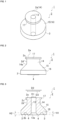
- FIG. 1 is a perspective view showing a schematic configuration of a connector 1 of the present embodiment
- FIG. 2 is a front view showing a schematic configuration of a connector 1 of the present embodiment
- FIG. 3 is a cross-sectional view showing a schematic configuration of a connector 1 of the present embodiment.
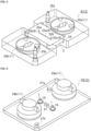
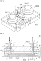
- FIG. 4 is an explanatory view showing a fluid device 5 and a lower holder 9
- FIG. 5 is an explanatory view showing an upper holder 10 mounted with a connector 1
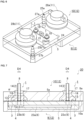
- FIG. 6 is an explanatory view showing a state in which the upper holder 10 and the lower holder 9 are superposed on each other
- FIG. 7 is a cross-sectional view schematically showing a state in which the upper holder 10 and the lower holder 9 are superposed on each other in FIG. 6
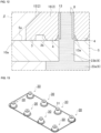
- FIG. 8 is an enlarged cross-sectional view of a region ⁇ enclosed by the broken line in FIG. 7
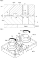
- FIG. 9 is an explanatory view showing a clamp operation by a clamp part 11, FIG.
- FIG. 10 is an explanatory view showing a device connection structure 20 after the clamp operation
- FIG. 11 is a cross-sectional view schematically showing the device connection structure 20 of FIG. 10
- FIG. 12 is an enlarged cross-sectional view of a region ⁇ enclosed by the broken line in FIG. 11
- FIG. 13 is an explanatory view showing an example of the supply of a fluid 7 to a micro flow path 31 via a plurality of connectors 30.
- the elastically deformable elastic rubber material for forming the connector 1 of the present embodiment in which the connector body 2, the guide part 3, and the lip part 4 are integrally formed is not particularly limited, and for example, silicon rubber, butylrubber, halogenated butylrubber, vinyl modified butylrubber, ethylene propylene-based rubber, fluoro rubber, acrylic rubber, or hydrogen-added nitrile rubber or the like can be used.
- the elastic rubber material can be formed into the shape of the connector 1 of the present embodiment by using a molding die made in accordance with the shape of the connector 1 designed in advance and using a well-known rubber molding technique such as extrusion or injection molding.
- a connector body 2 has a tube insertion hole 13 that is formed between a connector upper surface 2a and a connector lower surface 2b opposite to the connector upper surface 2a in parallel thereto.
- the tube insertion hole 13 is formed so that a tube 8 for supplying a fluid 7 to the micro flow path 6 formed inside the fluid device 5 or discharging the fluid 7 from the micro flow path 6 can be inserted therein for connection (see FIG. 9 or FIG. 10 ).
- the tube insertion hole 13 is formed so as to penetrate the center of the connector of the connector 1 of the present embodiment along the vertical direction and to maintain a constant tube insertion hole diameter D1.
- the material of the tube 8, which is made of resin and inserted into the tube insertion hole 13, is not particularly limited, and various resin materials and the like can be used as in the above-described connector 1, and it is particularly preferable to use a silicone rubber having excellent biocompatibility and excellent chemical resistance.
- the connector body 2 includes an upper connector body 14 including a connector upper surface 2a, a part of the tube insertion hole 13 formed in the center, and having a cylindrical shape, and a lower connector body 16 including a connector lower surface 2b, a remaining part of the tube insertion hole 13 formed in the center, and including a tapered part 15 extending from a lower end 14a of the upper connector body 14 toward the connector lower surface 2b so as to be enlarged in diameter.
- the connector body 2 is mainly composed of two members: an upper connector body 14 having a substantially cylindrical shape and a lower connector body 16 having a truncated conical shape.
- the connector body 2 By providing the connector body 2 with the above-described characteristic configuration, in particular, by configuring the lower connector body to have a tapered part 15 and a substantially trapezoidal cross-section, when the connector body is pressed against the fluid device 5 mounted and supported by a device holder 12 (see FIG. 4 and the like) to be described later, and a compressive load is applied from the vertical direction, the compression excess applied to the tapered part 15 of the connector 1 can be dispersed in the force to press the lip part 4 in the vertical downward direction toward the fluid device 5 (corresponding to the downward direction of the paper surface in FIG. 11 ), and the force to press the tube 8 inserted into the tube insertion hole 13 toward the center direction of the tube insertion hole 13 (or the tube 8).
- the guide part 3 of the connector 1 of the present embodiment protrudes downward from the connector lower surface 2b along a lower end peripheral edge of the connector body 2 (lower connector body 16), and is formed so as to be able to be brought into contact with a part of the fluid device 5. Since the connector 1 includes the guide part 3, the connector 1 capable of being brought into contact with a part of the fluid device 5, is brought into contact with the fluid device 5 with a gap between the device surface 5a of the fluid device 5 and the connector lower surface 2b. That is, the connector lower surface 2b can be positioned above the device surface 5a by the guide part protruding height H1 of the guide part 3 protruding from the connector lower surface 2b without the connector lower surface 2b directly contacting the device surface.
- the lip part 4 of the connector 1 of the present embodiment is formed to surround the periphery of a lower end opening 13a of the tube insertion hole 13 opened to the connector lower surface 2b in a circular shape, to protrude downward from the connector lower surface 2b and protrude higher than the guide part protruding height H1 of the guide part 3, and to be capable of being brought into contact with a part of the fluid device 5. That is, the lip part 4 has a lip part protruding height H2 higher than the guide part protruding height H1 of the guide part 3, and for example, as shown in a lateral view of the connector 1 shown in FIG. 2 or a cross-sectional view of the connector 1 shown in FIG. 3 , the tip of the lip part 4 is formed so as to protrude beyond the tip of the guide part 3.
- the tip of the lip part 4 protrudes beyond the guide part 3 as described above.
- the lip part 4 formed integrally with the connector body 2 or the like of an elastically deformable elastic rubber material is deformed such that the tip part of the lip part 4 is crushed, and the guide part protruding height H1 of the guide part 3 and the lip part protruding height H2 of the lip part 4 temporarily become the same height.
- the elastic repulsive force of the lip part 4 exerts a strong pressing force on the device surface 5a that comes into contact with the lip part.
- a high sealing property can be achieved between the lip part 4 and the fluid device 5.
- the connector 1 of the present embodiment further includes a flange 17 protruding horizontally from a connector-side peripheral surface 2d along an upper end peripheral edge 2c of the connector body 2 (the upper connector body 14).
- the first connector diameter D2 of the upper connector body 14 including the flange 17 is formed so as to be approximately 0.3mm to 0.5mm larger than the second connector diameter D3 of the upper connector body 14 not including the flange 17 (the connector-side peripheral surface 2d corresponds to the outer surface) (see FIG. 3 ).
- the flange 17 corresponds to a so-called "barb portion", and when the connector 1 is mounted to a connector mounting hole 18 of the upper holder 10, the movement of the connector 1 can be restricted. As a result, it is possible to provide a fall-off prevention function that prevents the connector 1, once mounted, from easily falling off the upper holder 10.
- the second connector diameter D3 not including the flange 17 is formed so as to substantially coincide with the hole diameter of the narrowest part of the connector mounting hole 18.
- the tube insertion hole diameter D1 (see FIG. 3 ) of the tube insertion hole 13 formed through the connector body 2 (the upper connector body 14 and the lower connector body 16) is set to be smaller than the tube outer diameter D4 (see FIG. 7 ) of the tube 8 inserted into and connected to the tube insertion hole 13.
- the tube 8 can be inserted into the tube insertion hole 13 as it is even when the tube insertion hole diameter D1 is set smaller than the tube outer diameter D4 of the tube 8 as described above, and the outer surface of the tube 8 is brought into close contact with the tube insertion hole 13. As a result, the tube 8 and the connector 1 can be connected with a simple operation, and the leakage of the fluid 7 or the like from between the tube 8 and the tube insertion hole 13 is prevented.
- the tube insertion hole diameter D1 and the tube outer diameter D4 can be set arbitrarily, but in consideration of the mounting operation and the like, for example, it is preferable to set the tube insertion hole diameter D1 to be approximately 0.05 to 0.10mm smaller than the tube outer diameter D4.
- connection structure 20 of the fluid device using the connector 1 of the present embodiment described in 1. above (corresponding to the connection structure of the micro fluid device of the present invention.
- device connection structure 20 simply referred to as the "device connection structure 20"
- the configurations of the connector 1 and the like described above are denoted by the same reference numerals, and detailed descriptions thereof will be omitted.
- the device connection structure 20 of the present embodiment mainly includes a connector 1 made of an elastic rubber material such as silicone resin, a fluid device 5 formed with a micro flow path 6 therein, and a device holder holding the connector 1 and the fluid device 5 sandwiched therebetween.
- the device holder 12 mainly includes an upper holder 10 having a connector mounting hole 18 into which the connector 1 can be mounted and being disposed from above the fluid device 5, a lower holder 9 for mounting the fluid device 5 and supporting it from below, and a clamp part 11 for fixing the connector 1 mounted on the upper holder 10 and the fluid device 5 mounted and supported on the lower holder 9 in close contact with each other in a state in which the upper holder 10 and the lower holder 9 are vertically overlapped.
- a fluid device 5 with a micro flow path 6 is placed in a lower holder 9 (see FIG. 4 ).
- the fluid device 5 has a substantially rectangular parallelepiped shape, and the micro flow path 6 is formed inside the fluid device 5.
- the micro flow path 6 is formed with a straight pipe section 23a having a straight pipe-shape formed along the longitudinal direction of the fluid device 5, and a pair of vertical pipe sections 23b and 23c that are bent vertically upward (toward the device surface 5a) from the respective ends of the straight pipe section 23a and have flow path openings 22a and 22b that open to the device surface 5a.
- the micro flow path 6 having such a configuration allows the fluid 7 supplied from one flow path opening 22a (corresponding to the supply port) that comes into contact with the connector 1 connected to the tube 8 to pass through one of the vertical pipe section 23b, the straight pipe section 23a, and the other vertical pipe section 23c (corresponding to the discharge port), and to be discharged to the outside of the fluid device 5 and the device connection structure 20 through the other flow path opening 22b.
- the lower holder 9 is configured to include a device mounting and supporting part 24 for mounting the fluid device 5 and supporting it from below, positioning projections 25a and 25b for aligning the overlapping position with the upper holder 10, and clamp receiving parts 26a and 26b constituting a part of the clamp part 11 for performing a clamp operation of the upper holder 10 and the lower holder 9, respectively.
- the device mounting and supporting part 24 is formed such that the device surface 5a of the mounted fluid device 5 and the holder upper surface 9a of the lower holder 9 are flush with each other (see FIGs. 7 and 8 ).
- the upper holder 10 has a connector mounting hole 18 formed therethrough, into which the connector 1 can be mounted, and further includes positioning holes 27a and 27b provided so as to correspond to the positions of the positioning projections 25a and 25b of the lower holder 9, clamp operation parts 28a and 28b constituting a part of the clamp part 11 for performing a clamp operation, and an observation hole 21 for observing a state in the micro flow path 6.
- a pair of connector mounting holes 18 are provided in parallel, and a position where the connector mounting holes 18 are provided is a position opposed to flow path openings 22a and 22b of the above-described micro flow path 6 when the upper holder 10 and the lower holder 9 are overlapped. That is, the lower end opening 13a of the tube insertion hole 13 of the connector 1 mounted in the connector mounting hole 18 and flow path openings 22a and 22b of the micro flow path 6 are opposed to each other.
- a flange 17 is provided at the upper part of the connector 1 (see FIG. 3 and the like).
- the connector 1 when the connector 1 is mounted in the connector mounting hole 18 of the upper holder 10, the connector 1, which is formed of an elastically deformable elastic rubber material (for example, silicone) and is in the vicinity of the flange 17, is crushed and deformed so as to be smaller than the hole diameter of the connector mounting hole 18, and then the connector is mounted. After the upper part of the connector body 2 including the flange 17 passes through the connector mounting hole 18, the force of crushing the connector 1 is released.
- an elastically deformable elastic rubber material for example, silicone
- the connector body 2 in the vicinity of the deformed flange 17 is elastically returned, and the connector 1 is fitted into the connector mounting hole 18 of the upper holder 10 as shown in FIG. 7 , for example.
- the connector mounting hole 18 provided in the upper holder 10 is provided with a hole shape so as to substantially match the appearance shape of the connector 1 having a tapered part 15, and the height of the tip of the guide part 3 and the holder lower surface 10a of the upper holder 10 are set to coincide with each other when the connector 1 is fitted into the connector mounting hole 18.
- the movement in the vertical direction in FIG. 7 of the connector 1 in a state of being mounted on the upper holder 10 is restricted by the action of the flange 17 provided in the connector 1. Consequently, when the fluid 7 is supplied to the micro flow path 6 or when the fluid 7 is discharged from the micro flow path 6, the connector 1 is not easily detached from the upper holder 10. That is, the flange 17 can function as a so-called "barb portion".
- the upper holder 10 to which a pair of connectors 1 are mounted is superimposed on the lower holder 9 to which the fluid device 5 is mounted and supported.
- a pair of positioning projections 25a and 25b provided in the lower holder 9 are respectively inserted into a pair of positioning holes 27a and 27b provided in the upper holder 10.
- the upper holder 10 and the lower holder 9 can be overlapped with each other at the correct position.
- FIG. 8 is an enlarged view of a region ⁇ surrounded by a broken line in FIG. 7.
- FIG. 7 shows a state in which the tube 8 is inserted into the tube insertion hole 13. Further, the tube 8 is shown only in the vicinity of the connector 1, and other parts are not shown (the same in FIGs. 9 to 11 ).
- a clamp operation is performed in which the clamp operation parts 28a and 28b of the clamp part 11 are rotated clockwise (rotated in the clamp operation direction CL) while the tubes 8 made of resin are inserted into the tube insertion holes 13 of the pair of connectors 1.
- a force is applied in a direction that brings the upper holder 10 and the lower holder 9 close to each other, and the holder lower surface 10a of the upper holder 10 and the holder upper surface 9a of the lower holder 9 come into contact with each other.
- a compressive load is applied to the connector 1 mounted on the upper holder 10 and the fluid device 5 mounted and supported on the lower holder 9 in the vertical direction so as to bring them close to each other.
- the connector 1 is integrally formed of silicone rubber, which is an elastic rubber material, and when such a compressive load is applied, a part of the lip part 4 (particularly a tip part) provided in the connector 1 is deformed by contact with the device surface 5a (see FIGs. 10 to 12 ). Consequently, the above-described gap S is eliminated, and the gap between the lower end opening 13a of the tube insertion hole 13 of the connector 1 and the flow path opening 22a (or flow path opening 22b) of the micro flow path 6 is sealed by the lip part 4 formed so as to surround the lower end opening 13a.
- the connector 1 since the connector 1 includes the lower connector body 16 having the tapered part 15, the connection state between the tube 8 inserted into the tube insertion hole 13 and the connector 1 is stabilized. As a result, it is possible to regulate the movement of the fluid 7 supplied through the tube 8, from the sealed space to the lateral direction of FIG. 7 and FIG. 8 . Therefore, the construction of the device connection structure 20 of the present embodiment is completed.
- the fluid 7 is supplied to the micro flow path 6 through one connector 1 connected to the tube 8, as shown in FIGs. 10 to 12 .
- the fluid 7 can be stably supplied to the micro flow path 6 while a sufficient sealing property between the lip part 4 and the device surface 5a is maintained by the lip part 4 and a sealing property between the tube 8 and the connector 1 is maintained, and operations and processes for various experiments such as culturing of cells and the like can be performed.
- the connector 1 of the present embodiment has the lower connector body 16 having the tapered part 15
- the close state between the tube 8 and the tube insertion hole 13 of the connector 1 and the close state between the lip part 4 of the connector 1 and the device surface 5a of the fluid device 5 can be strengthened when a compressive load in the vertical direction is applied to the connector 1 and the fluid device 5 by the clamp operation. This prevents leakage of the fluid 7 at the connecting part of the tube 8 and the fluid device 5.
- the lip part 4 protrudes beyond the guide part 3, the elastic deformation force of the lip part 4 can be increased, and the sealing property of the fluid 7 can be further improved.
- the connector mounting hole 18 of the upper holder 10 of the device holder 12 is formed with a tapered part corresponding to the tapered part 15 of the connector 1. This makes it possible to strengthen the close contact between the tube 8 and the tube insertion hole 13 of the connector 1 and the close contact between the lip part 4 of the connector 1 and the device surface 5a of the fluid device 5, and the upper holder 10 and the connector 1 can be brought into close contact with each other, thereby improving the sealing property between the connector 1 and the device holder 12.
- one connector 1 is connected to each of the flow path openings 22a, 22b, and the like of the micro flow path 6, but the present invention is not limited thereto, and, for example, as shown in FIG. 13 , as long as it is possible to apply a sufficiently compressive load by a device holder (not shown), two or more connectors 30 may be provided to match the flow path openings of the fluid device side.
- the connector and the fluid connection structure of the present invention can be suitably used in various processes and operations in a micro flow path by a micro fluid device.
Landscapes
- Chemical & Material Sciences (AREA)
- Health & Medical Sciences (AREA)
- Clinical Laboratory Science (AREA)
- Chemical Kinetics & Catalysis (AREA)
- Engineering & Computer Science (AREA)
- General Engineering & Computer Science (AREA)
- Dispersion Chemistry (AREA)
- Analytical Chemistry (AREA)
- General Health & Medical Sciences (AREA)
- Hematology (AREA)
- Mechanical Engineering (AREA)
- Quick-Acting Or Multi-Walled Pipe Joints (AREA)
Abstract
A connector 1 includes a connector body 2 having a tube insertion hole 13 that is formed between a connector upper surface 2a and a connector lower surface 2b and into which a tube can be inserted and connected; a guide part 3 that protrudes downward from the connector lower surface 2b along a lower end peripheral edge of the connector body 2 and is capable of being brought into contact with a part of a micro fluid device; and a lip part 4 that surrounds a lower end opening 13a of the tube insertion hole 13 opened to the connector lower surface 2b, protrudes downward from the connector lower surface 2b, protrudes higher than the guide part 3, and is capable of being brought into contact with a part of the micro fluid device, wherein the connector body 2, the guide part 3, and the lip part 4 are integrally formed by an elastically deformable elastic rubber material.
Description
- The present invention relates to a connector and a connection structure for a micro fluid device, and more particularly, to a connector interposed between a tube for supplying a fluid to a micro flow path formed inside a micro fluid device and a micro fluid device, and a connection structure for a micro fluid device using the connector.
- Conventionally, there has been known a micro fluid device for forming a fine flow path called a micro flow path having an flow path diameter of several micrometers to several hundred micrometers inside a resinous material or a glass material and performing various operations and processes such as separating, concentrating, reacting, and analyzing while flowing various fluids, including liquids such as a culture solution or a reaction solution, or a powder, through the micro flow path, on a microscale, by applying a semiconductor microfabrication technique or the like.
- By using such a micro fluid device, for example, a flow of blood or the like in a blood vessel can be reproduced in a micro flow path, or a biological experiment such as a cell culture or a tissue culture, a medical inspection, or the like can be performed in three dimensions and with a flow of a fluid, compared to the conventional method using a petri dish or the like.
- As a result, various experiments and inspections can be performed in a state close to the actual environment and conditions, and further, the use amount of fluids, chemicals, and the like to be used can be reduced by being performed on a microscale, and the reaction and the like can be efficiently performed. As such, there has been an increasing opportunity to use a micro fluid device, particularly in recent years in various fields.
- When various operations are performed using a micro fluid device, a supply operation (for example, a liquid supply operation) for stably supplying a fluid such as a culture solution to a fine micro flow path needs to be performed. For example, a method is known in which a micro pipette equipped with a pipette chip is used to inject a predetermined amount of fluid into a micro flow path.
- Further, there is also known a method in which conventionally known fluid supply means such as a pump or a syringe are used, and the fluid supply means and the micro fluid device are connected to each other by a resin tube made of a resin material such as silicone rubber, and a certain amount of fluid is continuously supplied into the micro flow path through the tube.
- In the method of continuously supplying a fluid as described above, it is required to connect the distal end of the tube having a hollow tubular shape and one flow path opening (supply port side) of the micro flow path, and to pour a fluid such as a liquid into the micro flow path at a predetermined flow rate, and to prevent the occurrence of a defect such as the leakage of the fluid from the connecting part of the tube and the flow path opening. Therefore, a connector (resin connector) formed of a resin material or the like may be interposed between the tube and the micro fluid device (for example, refer to Patent Document 1).
- As an example of a conventional connector interposed between a tube and a micro fluid device, for example, a connector configured in a so-called "set screw" shape in which a tube insertion hole that passes through the central part and into which a tube can be inserted is provided, and a male screw is formed on one end side of the connector, is known.
- On the other hand, a device holder (holder jig) that supports the micro fluid device to which the connector is connected is provided with a connector receiving part in which a female screw that can be screwed with a male screw part of the connector is formed, and the connector receiving part and the flow path opening of the micro flow path of the fluid device are formed in communication.
- In a state in which a tube made of resin or the like is connected to a tube insertion hole of the connector, when a male screw on the connector side and a female screw on the fluid device side are screwed together, the connector and the fluid device can be connected to each other, and when the connector is fastened and fixed by screwing the male screw and the female screw, the tube and the fluid device can be connected via the connector, and the leakage of fluid from the connecting part of the tube and the fluid device can be prevented by screwing the male screw and the female screw.
- As a result, a fluid such as a culture solution supplied from a tube made of resin through a fluid supply unit can be supplied through a supply port to a space inside a micro flow path formed inside the micro fluid device through a connector, and various operations and processes such as culturing of cells and the like can be performed by using fluids supplied into the micro flow path and flowing therethrough.
- The fluid that has passed through the micro flow path is discharged from the other flow path opening (discharge port side) of the micro fluid path to the outside of the micro fluid device. In addition, a connector connected to the tube is interposed in the flow path opening on the discharge side in the same way as the supply side, and the fluid is discharged while the leakage of the fluid is prevented between the micro fluid device and the tube.
- Furthermore, in the
above Patent Document 1, a device structure in which a packing (seal member) formed of a resin material is interposed between the tube and the fluid device to prevent the leakage of the fluid by the seal member, which is a further development of the connection structure of the micro fluid device using the connector that utilizes the screwing of the male screw and the female screw described above, is also proposed. - [Patent Document 1]
JP-A-2006-337032 - However, the connector and the connection structure of the micro fluid device described above may cause the following problems.
- In other words, in the case of the connector that utilizes the screwing of the male screw and the female screw, the connector in which the tube is connected needs to be screwed to the connector receiving part, and depending on the degree of fastening of the connector to the connector receiving part (degree of screwing), a part of the tube insertion hole inside the connector may be blocked, or a part of the micro flow path connected to the connector receiving part may be blocked. Therefore, it is necessary to pay sufficient attention to the mounting operation of the connector to the connector receiving part, and mounting such a connector may take time and may impose an excessive work load on the operator, such as troublesome work and complicated adjustment.
- Further, there is a possibility that a large amount of time is required for the troublesome work and complicated adjustment, and it may take a lot of time for an operator (a person in charge of an experiment, a work executor, or the like) who performs an experiment such as cell culture to prepare before starting an actual experiment. Further, when an operator is inexperienced in preparing experiments, there may be a variation in the mounting operation (tightening operation) of the connector to the connector receiving part, which can result in unstable flow of the fluid in the micro flow path and make it difficult to perform highly accurate cellular experiments and the like.
- On the other hand, even in the case of a connection structure in which a conventional seal member such as a packing is interposed, a defect such as the leakage of the fluid may occur. Further, due to insufficient tightening of the seal member, the seal member may be detached from the device holder, or the seal member may not provide a sufficient seal. As a result, the leakage of the fluid or the like occurs in the same manner as described above, and the experimental accuracy cannot be sufficiently ensured in some cases.
- In view of the above circumstances, an object of the present invention is to provide a connector formed with a relatively simple structure for connecting a tube for supplying or discharging fluid to a fluid device to supply a fluid to a micro flow path, and capable of easily performing a connecting operation between a tube and a micro fluid device, and a connection structure for a micro fluid device using the connector.
- According to the present invention, a connector and a connection structure for a micro fluid device that solve the above problems are provided below.
- [1] A connector comprising: a connector body having a tube insertion hole that is formed between a connector upper surface and a connector lower surface opposite to the connector upper surface and into which a tube used for supplying a fluid to a micro flow path formed inside a micro fluid device or discharging the fluid from the micro flow path can be inserted and connected; a guide part that protrudes downward from the connector lower surface along a lower end peripheral edge of the connector body and is capable of being brought into contact with a part of the micro fluid device; and a lip part that surrounds a lower end opening of the tube insertion hole opened to the connector lower surface, protrudes downward from the connector lower surface, protrudes higher than the guide part, and is capable of being brought into contact with a part of the micro fluid device, wherein the connector body, the guide part, and the lip part are integrally formed of an elastically deformable elastic rubber material.
- [2] The connector according to [1], wherein the connector body includes an upper connector body including the connector upper surface and having a cylindrical shape, and a lower connector body including the connector lower surface and having a tapered part extending from a lower end of the upper connector body toward the connector lower surface so as to be enlarged in diameter.
- [3] The connector according to [1] or [2], further comprising a flange that protrudes horizontally from a connector-side peripheral surface along an upper end peripheral edge of the connector body.
- [4] The connector according to [1] or [2], wherein an insertion hole diameter of the tube insertion hole is set to be smaller than an outer diameter of the tube to be inserted and connected.
- [5] The connector according to [3], wherein a flange outer diameter of the flange is set to be larger than a connector mounting hole of a device holder to which the connector can be mounted.
- [6] The connector according to [1] or [2], wherein the elastic rubber material is a silicone rubber.
- [7] A connection structure for a micro fluid device using the connector according to [1] or [2], comprising: a connector having a connector body having a tube insertion hole; a guide part; and a lip part, wherein the connector body, the guide part and the lip part are integrally formed of an elastically deformable elastic rubber material, and a tube is connected to the tube insertion hole; a micro fluid device having a micro flow path formed therein; and a device holder including an upper holder, a lower holder, and a clamp part that holds the connector and the micro fluid device in a state of being sandwiched between the upper holder and the lower holder, wherein the lower end opening of the tube insertion hole opened to the connector lower surface of the connector is aligned with a position opposed to the flow path opening of the micro flow path of the micro fluid device, and the connector and the micro fluid device are sandwiched between the upper holder and the lower holder from above and below by using the clamp part, thereby holding close contact between a lip part protruding from the connector lower surface of the connector and the micro fluid device.
- The connector of the present invention is formed in a relatively simple structure, and the connection between the tube and the micro fluid device can be performed in a simple and short time, and the connection structure for the micro fluid device of the present invention can be constructed. The connection structure for the micro fluid device using the connector of the present invention can reduce the time required for various operations such as culture experiments and preparation for processing, reduce the number of work steps, and eliminate the complexity of the work process.
-
-
FIG. 1 is a perspective view showing a connector of an embodiment of the present invention. -
FIG. 2 is a front view of a connector of the present embodiment. -
FIG. 3 is a cross-sectional view showing a connector of the present embodiment. -
FIG. 4 is an explanatory view showing a fluid device and a lower holder. -
FIG. 5 is an explanatory view showing an upper holder mounted with a connector. -
FIG. 6 is an explanatory view showing a state in which the upper holder and the lower holder are superposed on each other. -
FIG. 7 is a cross-sectional view schematically showing a state in which the upper holder and the lower holder are superposed on each other inFIG. 6 . -
FIG. 8 is an enlarged cross-sectional view of a region α enclosed by the broken line inFIG. 7 . -
FIG. 9 is an explanatory view showing a clamp operation by a clamp part. -
FIG. 10 is an explanatory view showing a connection structure of a micro fluid device after the clamp operation. -
FIG. 11 is a cross-sectional view schematically showing the connection structure of the micro fluid device ofFIG. 10 . -
FIG. 12 is an enlarged cross-sectional view of a region β enclosed by the broken line inFIG. 11 . -
FIG. 13 is an explanatory view showing an example of the supply of a fluid to a micro flow path via a plurality of connectors. - Hereinafter, embodiments of a connector and a connection structure for a micro fluid device (hereinafter, simply referred to as a "device connection structure") of the present invention will be described with reference to the drawings. Note that the connector and the device connection structure of the present invention are not limited to those shown below, and various design changes, modifications, improvements, and the like can be made without departing from the gist of the present invention.
- As shown mainly in
FIGs. 1 to 3 , aconnector 1 of an embodiment of the present invention mainly includes aconnector body 2, aguide part 3, and alip part 4, and theconnector body 2, theguide part 3, and thelip part 4 are integrally formed of an elastically deformable elastic rubber material. - By using the
connector 1 of the present embodiment, atube 8 made mainly of resin for supplying afluid 7 such as a liquid to amicro fluid path 6 formed inside a micro fluid device 5 (hereinafter, simply referred to as a "fluid device 5") or discharging thefluid 7 from themicro flow path 6 can be connected to thefluid device 5 without leakage of thefluid 7, so that thedevice connection structure 20 of the present invention can be constructed (seeFIGs. 10 to 12 ). - Here,
FIG. 1 is a perspective view showing a schematic configuration of aconnector 1 of the present embodiment,FIG. 2 is a front view showing a schematic configuration of aconnector 1 of the present embodiment, andFIG. 3 is a cross-sectional view showing a schematic configuration of aconnector 1 of the present embodiment. - In addition,
FIG. 4 is an explanatory view showing afluid device 5 and alower holder 9,FIG. 5 is an explanatory view showing anupper holder 10 mounted with aconnector 1,FIG. 6 is an explanatory view showing a state in which theupper holder 10 and thelower holder 9 are superposed on each other,FIG. 7 is a cross-sectional view schematically showing a state in which theupper holder 10 and thelower holder 9 are superposed on each other inFIG. 6 ,FIG. 8 is an enlarged cross-sectional view of a region α enclosed by the broken line inFIG. 7 ,FIG. 9 is an explanatory view showing a clamp operation by aclamp part 11,FIG. 10 is an explanatory view showing adevice connection structure 20 after the clamp operation,FIG. 11 is a cross-sectional view schematically showing thedevice connection structure 20 ofFIG. 10 ,FIG. 12 is an enlarged cross-sectional view of a region β enclosed by the broken line inFIG. 11 , andFIG. 13 is an explanatory view showing an example of the supply of afluid 7 to amicro flow path 31 via a plurality ofconnectors 30. - The elastically deformable elastic rubber material for forming the
connector 1 of the present embodiment in which theconnector body 2, theguide part 3, and thelip part 4 are integrally formed is not particularly limited, and for example, silicon rubber, butylrubber, halogenated butylrubber, vinyl modified butylrubber, ethylene propylene-based rubber, fluoro rubber, acrylic rubber, or hydrogen-added nitrile rubber or the like can be used. - Various operations and processes of the
fluid device 5 using theconnector 1 in themicro flow path 6 are often performed on a microscale basis, for example in experiments in the biological field such as cell culture, or experiments in the chemical field using various chemicals. Therefore, among the elastic rubber materials listed above, it is preferable to use a silicone rubber that is particularly excellent in biocompatibility and excellent in chemical resistance. The elastic rubber material can be formed into the shape of theconnector 1 of the present embodiment by using a molding die made in accordance with the shape of theconnector 1 designed in advance and using a well-known rubber molding technique such as extrusion or injection molding. - To explain each component in more detail, a
connector body 2 has atube insertion hole 13 that is formed between a connectorupper surface 2a and a connectorlower surface 2b opposite to the connectorupper surface 2a in parallel thereto. Thetube insertion hole 13 is formed so that atube 8 for supplying afluid 7 to themicro flow path 6 formed inside thefluid device 5 or discharging thefluid 7 from themicro flow path 6 can be inserted therein for connection (seeFIG. 9 orFIG. 10 ). - As shown in
FIG. 3 and the like, thetube insertion hole 13 is formed so as to penetrate the center of the connector of theconnector 1 of the present embodiment along the vertical direction and to maintain a constant tube insertion hole diameter D1. Here, the material of thetube 8, which is made of resin and inserted into thetube insertion hole 13, is not particularly limited, and various resin materials and the like can be used as in the above-describedconnector 1, and it is particularly preferable to use a silicone rubber having excellent biocompatibility and excellent chemical resistance. - Further, as shown mainly in
FIGs. 1 to 3 , theconnector body 2 includes anupper connector body 14 including a connectorupper surface 2a, a part of thetube insertion hole 13 formed in the center, and having a cylindrical shape, and alower connector body 16 including a connectorlower surface 2b, a remaining part of thetube insertion hole 13 formed in the center, and including atapered part 15 extending from alower end 14a of theupper connector body 14 toward the connectorlower surface 2b so as to be enlarged in diameter. That is, theconnector body 2 is mainly composed of two members: anupper connector body 14 having a substantially cylindrical shape and alower connector body 16 having a truncated conical shape. - By providing the
connector body 2 with the above-described characteristic configuration, in particular, by configuring the lower connector body to have a taperedpart 15 and a substantially trapezoidal cross-section, when the connector body is pressed against thefluid device 5 mounted and supported by a device holder 12 (seeFIG. 4 and the like) to be described later, and a compressive load is applied from the vertical direction, the compression excess applied to thetapered part 15 of theconnector 1 can be dispersed in the force to press thelip part 4 in the vertical downward direction toward the fluid device 5 (corresponding to the downward direction of the paper surface inFIG. 11 ), and the force to press thetube 8 inserted into thetube insertion hole 13 toward the center direction of the tube insertion hole 13 (or the tube 8). - This maintains a high sealing property between the
lip part 4 and thedevice surface 5a of thefluid device 5, and makes it possible to strengthen the adhesion between theconnector 1 and thetube 8. As a result, it is possible to suppress occurrence of a defect such as leakage of thefluid 7 between theconnector 1 and thefluid device 5 and between theconnector 1 and thetube 8. - Further, the
guide part 3 of theconnector 1 of the present embodiment protrudes downward from the connectorlower surface 2b along a lower end peripheral edge of the connector body 2 (lower connector body 16), and is formed so as to be able to be brought into contact with a part of thefluid device 5. Since theconnector 1 includes theguide part 3, theconnector 1 capable of being brought into contact with a part of thefluid device 5, is brought into contact with thefluid device 5 with a gap between thedevice surface 5a of thefluid device 5 and the connectorlower surface 2b. That is, the connectorlower surface 2b can be positioned above thedevice surface 5a by the guide part protruding height H1 of theguide part 3 protruding from the connectorlower surface 2b without the connectorlower surface 2b directly contacting the device surface. - In addition, the
lip part 4 of theconnector 1 of the present embodiment is formed to surround the periphery of alower end opening 13a of thetube insertion hole 13 opened to the connectorlower surface 2b in a circular shape, to protrude downward from the connectorlower surface 2b and protrude higher than the guide part protruding height H1 of theguide part 3, and to be capable of being brought into contact with a part of thefluid device 5. That is, thelip part 4 has a lip part protruding height H2 higher than the guide part protruding height H1 of theguide part 3, and for example, as shown in a lateral view of theconnector 1 shown inFIG. 2 or a cross-sectional view of theconnector 1 shown inFIG. 3 , the tip of thelip part 4 is formed so as to protrude beyond the tip of theguide part 3. - Therefore, when no compressive load is applied to the
connector 1, the tip of thelip part 4 protrudes beyond theguide part 3 as described above. On the other hand, when a compressive load is applied from the vertical direction to theconnector 1, thelip part 4 formed integrally with theconnector body 2 or the like of an elastically deformable elastic rubber material is deformed such that the tip part of thelip part 4 is crushed, and the guide part protruding height H1 of theguide part 3 and the lip part protruding height H2 of thelip part 4 temporarily become the same height. As a result, the elastic repulsive force of thelip part 4 exerts a strong pressing force on thedevice surface 5a that comes into contact with the lip part. As a result, a high sealing property can be achieved between thelip part 4 and thefluid device 5. - In addition to the above-described configuration, the
connector 1 of the present embodiment further includes aflange 17 protruding horizontally from a connector-sideperipheral surface 2d along an upper endperipheral edge 2c of the connector body 2 (the upper connector body 14). It is preferable that the first connector diameter D2 of theupper connector body 14 including the flange 17 (corresponding to the flange outer diameter in the present invention) is formed so as to be approximately 0.3mm to 0.5mm larger than the second connector diameter D3 of theupper connector body 14 not including the flange 17 (the connector-sideperipheral surface 2d corresponds to the outer surface) (seeFIG. 3 ). - By providing the
flange 17 in this manner, theflange 17 corresponds to a so-called "barb portion", and when theconnector 1 is mounted to aconnector mounting hole 18 of theupper holder 10, the movement of theconnector 1 can be restricted. As a result, it is possible to provide a fall-off prevention function that prevents theconnector 1, once mounted, from easily falling off theupper holder 10. - On the other hand, the second connector diameter D3 not including the
flange 17 is formed so as to substantially coincide with the hole diameter of the narrowest part of theconnector mounting hole 18. As described above, theflange 17 is set such that the first connector diameter D2 (=corresponding to the flange outer diameter) is larger than the hole diameter of the narrowest portion of theconnector mounting hole 18. - In the
connector 1 of the present embodiment, the tube insertion hole diameter D1 (seeFIG. 3 ) of thetube insertion hole 13 formed through the connector body 2 (theupper connector body 14 and the lower connector body 16) is set to be smaller than the tube outer diameter D4 (seeFIG. 7 ) of thetube 8 inserted into and connected to thetube insertion hole 13. - Since the
connector 1 is made of an elastically deformable elastic rubber material, thetube 8 can be inserted into thetube insertion hole 13 as it is even when the tube insertion hole diameter D1 is set smaller than the tube outer diameter D4 of thetube 8 as described above, and the outer surface of thetube 8 is brought into close contact with thetube insertion hole 13. As a result, thetube 8 and theconnector 1 can be connected with a simple operation, and the leakage of thefluid 7 or the like from between thetube 8 and thetube insertion hole 13 is prevented. The tube insertion hole diameter D1 and the tube outer diameter D4 can be set arbitrarily, but
in consideration of the mounting operation and the like, for example, it is preferable to set the tube insertion hole diameter D1 to be approximately 0.05 to 0.10mm smaller than the tube outer diameter D4. - Next, the
connection structure 20 of the fluid device using theconnector 1 of the present embodiment described in 1. above (corresponding to the connection structure of the micro fluid device of the present invention. Hereinafter, simply referred to as the "device connection structure 20") will be described. Note that, in thedevice connection structure 20 of the present embodiment, the configurations of theconnector 1 and the like described above are denoted by the same reference numerals, and detailed descriptions thereof will be omitted. - The
device connection structure 20 of the present embodiment mainly includes aconnector 1 made of an elastic rubber material such as silicone resin, afluid device 5 formed with amicro flow path 6 therein, and a device holder holding theconnector 1 and thefluid device 5 sandwiched therebetween. - As shown in
FIGs. 4 to 12 , thedevice holder 12 mainly includes anupper holder 10 having aconnector mounting hole 18 into which theconnector 1 can be mounted and being disposed from above thefluid device 5, alower holder 9 for mounting thefluid device 5 and supporting it from below, and aclamp part 11 for fixing theconnector 1 mounted on theupper holder 10 and thefluid device 5 mounted and supported on thelower holder 9 in close contact with each other in a state in which theupper holder 10 and thelower holder 9 are vertically overlapped. - By providing the above three configurations, it is possible to construct a
device connection structure 20 in which thelower end opening 13a of thetube insertion hole 13 of theconnector 1 is aligned to a position opposed to theflow path openings micro flow path 6 of thefluid device 5, theconnector 1 and thefluid device 5 are brought into close contact by using theclamp part 11, and the state is maintained (seeFIGs. 8 and11 ). - Details of the
device connection structure 20 of the present embodiment and details of the functions and effects of theconnector 1 by thedevice connection structure 20 will be described below mainly with reference toFIGs. 4 to 10 . - First, a
fluid device 5 with amicro flow path 6 is placed in a lower holder 9 (seeFIG. 4 ). Here, thefluid device 5 has a substantially rectangular parallelepiped shape, and themicro flow path 6 is formed inside thefluid device 5. Further, themicro flow path 6 is formed with astraight pipe section 23a having a straight pipe-shape formed along the longitudinal direction of thefluid device 5, and a pair ofvertical pipe sections device surface 5a) from the respective ends of thestraight pipe section 23a and haveflow path openings device surface 5a. - The
micro flow path 6 having such a configuration allows thefluid 7 supplied from one flow path opening 22a (corresponding to the supply port) that comes into contact with theconnector 1 connected to thetube 8 to pass through one of thevertical pipe section 23b, thestraight pipe section 23a, and the othervertical pipe section 23c (corresponding to the discharge port), and to be discharged to the outside of thefluid device 5 and thedevice connection structure 20 through the other flow path opening 22b. - Here, the
lower holder 9 is configured to include a device mounting and supportingpart 24 for mounting thefluid device 5 and supporting it from below,positioning projections upper holder 10, andclamp receiving parts clamp part 11 for performing a clamp operation of theupper holder 10 and thelower holder 9, respectively. Furthermore, the device mounting and supportingpart 24 is formed such that thedevice surface 5a of the mountedfluid device 5 and the holderupper surface 9a of thelower holder 9 are flush with each other (seeFIGs. 7 and8 ). - On the other hand, as shown in
FIG. 5 , theupper holder 10 has aconnector mounting hole 18 formed therethrough, into which theconnector 1 can be mounted, and further includespositioning holes positioning projections lower holder 9,clamp operation parts clamp part 11 for performing a clamp operation, and anobservation hole 21 for observing a state in themicro flow path 6. - Here, in the
upper holder 10, a pair ofconnector mounting holes 18 are provided in parallel, and a position where theconnector mounting holes 18 are provided is a position opposed to flowpath openings micro flow path 6 when theupper holder 10 and thelower holder 9 are overlapped. That is, thelower end opening 13a of thetube insertion hole 13 of theconnector 1 mounted in theconnector mounting hole 18 and flowpath openings micro flow path 6 are opposed to each other. - As described above, a
flange 17 is provided at the upper part of the connector 1 (seeFIG. 3 and the like). The first connector diameter D2 of the connector body 2 (the upper connector body 14) including theflange 17 is formed to be larger than the hole diameter (=the second connector diameter D3) of theconnector mounting hole 18. - Therefore, when the
connector 1 is mounted in theconnector mounting hole 18 of theupper holder 10, theconnector 1, which is formed of an elastically deformable elastic rubber material (for example, silicone) and is in the vicinity of theflange 17, is crushed and deformed so as to be smaller than the hole diameter of theconnector mounting hole 18, and then the connector is mounted. After the upper part of theconnector body 2 including theflange 17 passes through theconnector mounting hole 18, the force of crushing theconnector 1 is released. - As a result, the
connector body 2 in the vicinity of thedeformed flange 17 is elastically returned, and theconnector 1 is fitted into theconnector mounting hole 18 of theupper holder 10 as shown inFIG. 7 , for example. Further, theconnector mounting hole 18 provided in theupper holder 10 is provided with a hole shape so as to substantially match the appearance shape of theconnector 1 having atapered part 15, and the height of the tip of theguide part 3 and the holderlower surface 10a of theupper holder 10 are set to coincide with each other when theconnector 1 is fitted into theconnector mounting hole 18. - Further, the movement in the vertical direction in
FIG. 7 of theconnector 1 in a state of being mounted on theupper holder 10 is restricted by the action of theflange 17 provided in theconnector 1. Consequently, when thefluid 7 is supplied to themicro flow path 6 or when thefluid 7 is discharged from themicro flow path 6, theconnector 1 is not easily detached from theupper holder 10. That is, theflange 17 can function as a so-called "barb portion". - Next, as shown in
FIG. 6 , theupper holder 10 to which a pair ofconnectors 1 are mounted is superimposed on thelower holder 9 to which thefluid device 5 is mounted and supported. At this time, a pair ofpositioning projections lower holder 9 are respectively inserted into a pair ofpositioning holes upper holder 10. As a result, theupper holder 10 and thelower holder 9 can be overlapped with each other at the correct position. - At this time, the clamp operation by the
clamp part 11 is not performed. Therefore, as shown inFIG. 8 in whichFIG.7 and a partial area ofFIG. 7 are enlarged, a gap S is formed between theupper holder 10 and thelower holder 9. That is, since thelip part 4 protrudes from the connectorlower surface 2b higher than the guide part protruding height H1 of theguide part 3, thelip part 4 is in contact with thedevice surface 5a of thefluid device 5. Here,FIG. 8 is an enlarged view of a region α surrounded by a broken line inFIG. 7. FIG. 7 shows a state in which thetube 8 is inserted into thetube insertion hole 13. Further, thetube 8 is shown only in the vicinity of theconnector 1, and other parts are not shown (the same inFIGs. 9 to 11 ). - Thereafter, as shown in
FIG. 9 , a clamp operation is performed in which theclamp operation parts clamp part 11 are rotated clockwise (rotated in the clamp operation direction CL) while thetubes 8 made of resin are inserted into the tube insertion holes 13 of the pair ofconnectors 1. By the clamp operation, a force is applied in a direction that brings theupper holder 10 and thelower holder 9 close to each other, and the holderlower surface 10a of theupper holder 10 and the holderupper surface 9a of thelower holder 9 come into contact with each other. At this time, a compressive load is applied to theconnector 1 mounted on theupper holder 10 and thefluid device 5 mounted and supported on thelower holder 9 in the vertical direction so as to bring them close to each other. - That is, a force that eliminates the above-described gap S between the holder
lower surface 10a and the holderupper surface 9a is applied. Theconnector 1 is integrally formed of silicone rubber, which is an elastic rubber material, and when such a compressive load is applied, a part of the lip part 4 (particularly a tip part) provided in theconnector 1 is deformed by contact with thedevice surface 5a (seeFIGs. 10 to 12 ). Consequently, the above-described gap S is eliminated, and the gap between thelower end opening 13a of thetube insertion hole 13 of theconnector 1 and the flow path opening 22a (or flow path opening 22b) of themicro flow path 6 is sealed by thelip part 4 formed so as to surround thelower end opening 13a. Further, as described above, since theconnector 1 includes thelower connector body 16 having the taperedpart 15, the connection state between thetube 8 inserted into thetube insertion hole 13 and theconnector 1 is stabilized. As a result, it is possible to regulate the movement of thefluid 7 supplied through thetube 8, from the sealed space to the lateral direction ofFIG. 7 andFIG. 8 . Therefore, the construction of thedevice connection structure 20 of the present embodiment is completed. - While maintaining the sealed state between the
tube 8 and theconnector 1 and between theconnector 1 and thefluid device 5 in this manner, thefluid 7 is supplied to themicro flow path 6 through oneconnector 1 connected to thetube 8, as shown inFIGs. 10 to 12 . Thereby, thefluid 7 can be stably supplied to themicro flow path 6 while a sufficient sealing property between thelip part 4 and thedevice surface 5a is maintained by thelip part 4 and a sealing property between thetube 8 and theconnector 1 is maintained, and operations and processes for various experiments such as culturing of cells and the like can be performed. - In particular, since the
connector 1 of the present embodiment has thelower connector body 16 having the taperedpart 15, the close state between thetube 8 and thetube insertion hole 13 of theconnector 1 and the close state between thelip part 4 of theconnector 1 and thedevice surface 5a of thefluid device 5 can be strengthened when a compressive load in the vertical direction is applied to theconnector 1 and thefluid device 5 by the clamp operation. This prevents leakage of thefluid 7 at the connecting part of thetube 8 and thefluid device 5. Further, since thelip part 4 protrudes beyond theguide part 3, the elastic deformation force of thelip part 4 can be increased, and the sealing property of thefluid 7 can be further improved. Further, theconnector mounting hole 18 of theupper holder 10 of thedevice holder 12 is formed with a tapered part corresponding to thetapered part 15 of theconnector 1. This makes it possible to strengthen the close contact between thetube 8 and thetube insertion hole 13 of theconnector 1 and the close contact between thelip part 4 of theconnector 1 and thedevice surface 5a of thefluid device 5, and theupper holder 10 and theconnector 1 can be brought into close contact with each other, thereby improving the sealing property between theconnector 1 and thedevice holder 12. - In the
connector 1 and thedevice connection structure 20 of the present embodiment described above, oneconnector 1 is connected to each of theflow path openings micro flow path 6, but the present invention is not limited thereto, and, for example, as shown inFIG. 13 , as long as it is possible to apply a sufficiently compressive load by a device holder (not shown), two ormore connectors 30 may be provided to match the flow path openings of the fluid device side. - The connector and the fluid connection structure of the present invention can be suitably used in various processes and operations in a micro flow path by a micro fluid device.
-
- 1, 30: connector
- 2: connector body
- 2a: connector upper surface
- 2b: connector lower surface
- 2c: upper end peripheral edge
- 2d: connector-side peripheral surface
- 3: guide part
- 4: lip part
- 5: fluid device (micro fluid device)
- 5a: device surface
- 6, 31: micro flow path
- 7: fluid
- 8: tube
- 9: lower holder
- 9a: holder upper surface
- 10: upper holder
- 10a: holder lower surface
- 11: clamp part
- 12: device holder
- 13: tube insertion hole
- 13a: lower end opening
- 14: upper connector body
- 14a: lower end
- 15: tapered part
- 16: lower connector body
- 17: flange
- 18: connector mounting hole
- 20: device connection structure (connection structure of micro fluid device)
- 21: observation hole
- 22a, 22b: flow path opening
- 23a: straight pipe section
- 23b, 23c: vertical pipe section
- 24: device mounting and supporting part
- 25a, 25b: positioning projection
- 26a, 26b: clamp receiving part
- 27a, 27b: positioning hole
- 28a, 28b: clamp operation part
- CL: clamp operation direction
- D1: tube insertion hole diameter
- D2: first connector diameter
- D3: second connector diameter
- D4: tube outer diameter
- H1: guide part protruding height
- H2: lip part protruding height
- S: gap
- α, β: region enclosed by the broken line
Claims (7)
- A connector comprising:a connector body having a tube insertion hole that is formed between a connector upper surface and a connector lower surface opposite to the connector upper surface and into which a tube used for supplying a fluid to a micro flow path formed inside a micro fluid device or discharging the fluid from the micro flow path can be inserted and connected;a guide part that protrudes downward from the connector lower surface along a lower end peripheral edge of the connector body and is capable of being brought into contact with a part of the micro fluid device; anda lip part that surrounds a lower end opening of the tube insertion hole opened to the connector lower surface, protrudes downward from the connector lower surface, protrudes higher than the guide part, and is capable of being brought into contact with a part of the micro fluid device,wherein the connector body, the guide part, and the lip part are integrally formed of an elastically deformable elastic rubber material.
- The connector according to claim 1, wherein the connector body includesan upper connector body including the connector upper surface and having a cylindrical shape, anda lower connector body including the connector lower surface and having a tapered part extending from a lower end of the upper connector body toward the connector lower surface so as to be enlarged in diameter.
- The connector according to claim 1 or 2, further comprising a flange that protrudes horizontally from a connector-side peripheral surface along an upper end peripheral edge of the connector body.
- The connector according to claim 1 or 2, wherein an insertion hole diameter of the tube insertion hole is set to be smaller than an outer diameter of the tube to be inserted and connected.
- The connector according to claim 3, wherein a flange outer diameter of the flange is set to be larger than a connector mounting hole of a device holder to which the connector can be mounted.
- The connector according to claim 1 or 2, wherein the elastic rubber material is a silicone rubber.
- A connection structure for a micro fluid device using the connector according to claim 1 or 2, comprising:a connector having a connector body having a tube insertion hole; a guide part; and a lip part, wherein the connector body, the guide part and the lip part are integrally formed of an elastically deformable elastic rubber material, and a tube is connected to the tube insertion hole;a micro fluid device having a micro flow path formed therein; anda device holder including an upper holder, a lower holder, and a clamp part that holds the connector and the micro fluid device in a state of being sandwiched between the upper holder and the lower holder,wherein the lower end opening of the tube insertion hole opened to the connector lower surface of the connector is aligned with a position opposed to the flow path opening of the micro flow path of the micro fluid device, and the connector and the micro fluid device are sandwiched between the upper holder and the lower holder from above and below by using the clamp part, thereby holding close contact between a lip part protruding from the connector lower surface of the connector and the micro fluid device.
Applications Claiming Priority (2)
| Application Number | Priority Date | Filing Date | Title |
|---|---|---|---|
| JP2022103764 | 2022-06-28 | ||
| PCT/JP2023/017305 WO2024004380A1 (en) | 2022-06-28 | 2023-05-08 | Connector and connection structure for microfluidic device |
Publications (1)
| Publication Number | Publication Date |
|---|---|
| EP4549954A1 true EP4549954A1 (en) | 2025-05-07 |
Family
ID=89381912
Family Applications (1)
| Application Number | Title | Priority Date | Filing Date |
|---|---|---|---|
| EP23830832.4A Pending EP4549954A1 (en) | 2022-06-28 | 2023-05-08 | Connector and connection structure for microfluidic device |
Country Status (5)
| Country | Link |
|---|---|
| US (1) | US20250347367A1 (en) |
| EP (1) | EP4549954A1 (en) |
| JP (1) | JP7782043B2 (en) |
| CN (1) | CN119497823A (en) |
| WO (1) | WO2024004380A1 (en) |
Family Cites Families (7)
| Publication number | Priority date | Publication date | Assignee | Title |
|---|---|---|---|---|
| DE10238266A1 (en) * | 2002-02-28 | 2003-11-06 | Ibidi Gmbh | Microfluidic system |
| AU2003900329A0 (en) * | 2003-01-24 | 2003-02-13 | Microtechnology Centre Management Limited | Microfluidic connector |
| JP4479590B2 (en) | 2005-05-31 | 2010-06-09 | 株式会社島津製作所 | Piping connection method and microchip device |
| KR101563689B1 (en) * | 2009-03-13 | 2015-11-09 | 삼성전자주식회사 | Accessories for connecting tubes and microfluidic systems with them |
| WO2014011115A1 (en) * | 2012-07-12 | 2014-01-16 | Agency For Science, Technology And Research | A connector for microfluidic device, a method for injecting fluid into microfluidic device using the connector and a method of providing and operating a valve |
| JPWO2017208772A1 (en) * | 2016-05-30 | 2019-03-22 | Nok株式会社 | Liquid injection attachment |
| WO2018043119A1 (en) * | 2016-08-31 | 2018-03-08 | Nok株式会社 | Attachment for liquid injection |
-
2023
- 2023-05-08 WO PCT/JP2023/017305 patent/WO2024004380A1/en not_active Ceased
- 2023-05-08 JP JP2024530337A patent/JP7782043B2/en active Active
- 2023-05-08 EP EP23830832.4A patent/EP4549954A1/en active Pending
- 2023-05-08 US US18/879,409 patent/US20250347367A1/en active Pending
- 2023-05-08 CN CN202380049825.XA patent/CN119497823A/en active Pending
Also Published As
| Publication number | Publication date |
|---|---|
| JPWO2024004380A1 (en) | 2024-01-04 |
| CN119497823A (en) | 2025-02-21 |
| US20250347367A1 (en) | 2025-11-13 |
| JP7782043B2 (en) | 2025-12-08 |
| WO2024004380A1 (en) | 2024-01-04 |
Similar Documents
| Publication | Publication Date | Title |
|---|---|---|
| EP2982440B1 (en) | Attachment for liquid injection and liquid injection method | |
| CN104080507B (en) | Connector | |
| WO2021169251A1 (en) | In-vitro diagnostic analyzer and reagent card | |
| CN107106410B (en) | Connector system with at least two extraction ports | |
| JP2015199028A (en) | Method of injecting liquid into micro-channel | |
| US10843197B2 (en) | Fluidic connector, microfluidic chip cartridge, and fluidic connector assembly thereof | |
| WO2021147352A1 (en) | In-vitro diagnostic analyzer, reagent card, and mounting structure | |
| US20250347367A1 (en) | Connector and connection structure for micro fluid device | |
| CN113351267B (en) | Sealing matching joint module applied to quick detachment of microfluidic chip and operation platform thereof | |
| KR101319279B1 (en) | Bag with attached mouth member and connection structure of said bag | |
| US20250033041A1 (en) | Reagent pre-embedding and sample injecting device, and sample injection method therefor and application thereof | |
| EP3508857A1 (en) | Attachment for liquid injection | |
| JPWO2017208772A1 (en) | Liquid injection attachment | |
| EP3462158A1 (en) | Liquid injection attachment, and liquid injecting device | |
| US10882008B2 (en) | Apparatus for processing biological sample | |
| CN115672419A (en) | Fluid treatment system | |
| CN213933291U (en) | Sample pretreatment device | |
| JP2017166989A (en) | Micro flow path chip | |
| CN108025307A (en) | The mounting structure and liquid injection accessory of pipette or pipette tip with liquid injection with accessory | |
| CN112393960A (en) | Sample pretreatment device and sample pretreatment method using same | |
| CN101548182A (en) | Needle hub for fluid connection | |
| JP2023534148A (en) | sample prep tube | |
| EP4692808A1 (en) | Analysis device | |
| EP3473179A1 (en) | Emulsion production member, and sample collection tube and blood collection tube each equipped with same | |
| CN107406186B (en) | Joint structure for viscous liquid discharge device, and viscous liquid discharge device using the joint structure |
Legal Events
| Date | Code | Title | Description |
|---|---|---|---|
| STAA | Information on the status of an ep patent application or granted ep patent |
Free format text: STATUS: THE INTERNATIONAL PUBLICATION HAS BEEN MADE |
|
| PUAI | Public reference made under article 153(3) epc to a published international application that has entered the european phase |
Free format text: ORIGINAL CODE: 0009012 |
|
| STAA | Information on the status of an ep patent application or granted ep patent |
Free format text: STATUS: REQUEST FOR EXAMINATION WAS MADE |
|
| 17P | Request for examination filed |
Effective date: 20241122 |
|
| AK | Designated contracting states |
Kind code of ref document: A1 Designated state(s): AL AT BE BG CH CY CZ DE DK EE ES FI FR GB GR HR HU IE IS IT LI LT LU LV MC ME MK MT NL NO PL PT RO RS SE SI SK SM TR |
|
| DAV | Request for validation of the european patent (deleted) | ||
| DAX | Request for extension of the european patent (deleted) |