EP4549917A1 - Measurement system - Google Patents
Measurement system Download PDFInfo
- Publication number
- EP4549917A1 EP4549917A1 EP24209054.6A EP24209054A EP4549917A1 EP 4549917 A1 EP4549917 A1 EP 4549917A1 EP 24209054 A EP24209054 A EP 24209054A EP 4549917 A1 EP4549917 A1 EP 4549917A1
- Authority
- EP
- European Patent Office
- Prior art keywords
- region
- measurement
- measurement system
- test sample
- verification
- Prior art date
- Legal status (The legal status is an assumption and is not a legal conclusion. Google has not performed a legal analysis and makes no representation as to the accuracy of the status listed.)
- Pending
Links
Images











Classifications
-
- G—PHYSICS
- G01—MEASURING; TESTING
- G01N—INVESTIGATING OR ANALYSING MATERIALS BY DETERMINING THEIR CHEMICAL OR PHYSICAL PROPERTIES
- G01N33/00—Investigating or analysing materials by specific methods not covered by groups G01N1/00 - G01N31/00
- G01N33/48—Biological material, e.g. blood, urine; Haemocytometers
- G01N33/50—Chemical analysis of biological material, e.g. blood, urine; Testing involving biospecific ligand binding methods; Immunological testing
- G01N33/53—Immunoassay; Biospecific binding assay; Materials therefor
- G01N33/543—Immunoassay; Biospecific binding assay; Materials therefor with an insoluble carrier for immobilising immunochemicals
- G01N33/54366—Apparatus specially adapted for solid-phase testing
- G01N33/54386—Analytical elements
- G01N33/54387—Immunochromatographic test strips
-
- G—PHYSICS
- G01—MEASURING; TESTING
- G01N—INVESTIGATING OR ANALYSING MATERIALS BY DETERMINING THEIR CHEMICAL OR PHYSICAL PROPERTIES
- G01N21/00—Investigating or analysing materials by the use of optical means, i.e. using sub-millimetre waves, infrared, visible or ultraviolet light
- G01N21/75—Systems in which material is subjected to a chemical reaction, the progress or the result of the reaction being investigated
- G01N21/77—Systems in which material is subjected to a chemical reaction, the progress or the result of the reaction being investigated by observing the effect on a chemical indicator
- G01N21/78—Systems in which material is subjected to a chemical reaction, the progress or the result of the reaction being investigated by observing the effect on a chemical indicator producing a change of colour
-
- G—PHYSICS
- G01—MEASURING; TESTING
- G01N—INVESTIGATING OR ANALYSING MATERIALS BY DETERMINING THEIR CHEMICAL OR PHYSICAL PROPERTIES
- G01N21/00—Investigating or analysing materials by the use of optical means, i.e. using sub-millimetre waves, infrared, visible or ultraviolet light
- G01N21/84—Systems specially adapted for particular applications
- G01N21/8483—Investigating reagent band
-
- G—PHYSICS
- G01—MEASURING; TESTING
- G01N—INVESTIGATING OR ANALYSING MATERIALS BY DETERMINING THEIR CHEMICAL OR PHYSICAL PROPERTIES
- G01N21/00—Investigating or analysing materials by the use of optical means, i.e. using sub-millimetre waves, infrared, visible or ultraviolet light
- G01N21/84—Systems specially adapted for particular applications
- G01N21/88—Investigating the presence of flaws or contamination
- G01N21/93—Detection standards; Calibrating baseline adjustment, drift correction
-
- G—PHYSICS
- G01—MEASURING; TESTING
- G01N—INVESTIGATING OR ANALYSING MATERIALS BY DETERMINING THEIR CHEMICAL OR PHYSICAL PROPERTIES
- G01N21/00—Investigating or analysing materials by the use of optical means, i.e. using sub-millimetre waves, infrared, visible or ultraviolet light
- G01N21/75—Systems in which material is subjected to a chemical reaction, the progress or the result of the reaction being investigated
- G01N21/77—Systems in which material is subjected to a chemical reaction, the progress or the result of the reaction being investigated by observing the effect on a chemical indicator
- G01N2021/7756—Sensor type
- G01N2021/7759—Dipstick; Test strip
Definitions
- the present invention relates to a measurement system that optically measures a measurement target.
- a fluoroscopy detection device described in Japanese Patent Application Laid-Open ( JP-A) No. 2007-315772 is equipped with an illuminance sensor of a detection section, and in particular detects errors due to external light (extraneous stray light) when a shutter of an input port or an output port is not closed.
- a measurement system of an aspect of the present invention includes a first element in which a test sample carrier applied with a test sample suspected to contain a measurement target is to be held, a second element to which the first element is assembled, an imaging section capturing a verification area containing a measurement region in which the measurement target in the test sample applied to the test sample carrier is to be positioned in the first element and acquiring a verification image, and an analysis section analyzing the verification image and detecting an assembly error of the first element.
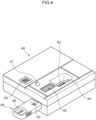
- Fig. 1 is an upper perspective view of a holder 40 serving as a first element employed in a measurement system 10 of the present exemplary embodiment (see Fig. 11 ).
- the measurement system 10 may include a holder 40 such as illustrated in Fig. 1 as a member configuring (providing) a housing 20 (see Fig. 8 ).
- the holder 40 has a box shape and is formed with two openings, i.e., a measurement opening section 43 and an identification opening section 44, in an upper face of the holder 40.
- a filter 45 with characteristics described later is fitted into the measurement opening section 43.
- a sensor 47 for sensing light is furthermore provided at the upper face of the holder 40.
- An insertion port 41 into which a test sample carrier 60 described later (see Fig.
- the interior space of the insertion port 41 is a space in communication with both the measurement opening section 43 and the identification opening section 44, and configures a housing section 46 that is a space in which a part of the test sample carrier 60 is housed.
- identification information 48 of the holder 40 serving as a first element is displayed in the vicinity of the measurement opening section 43 on the upper face of the holder 40 by, for example, a QR code (registered trademark).
- the holder 40 serving as a first element is configured such that the test sample carrier 60 applied with the measurement target is held therein.
- Fig. 2 is a lower perspective view illustrating an enlargement of a vicinity of the insertion port 41 of the holder 40.
- the sensor 47 is provided in the vicinity of the measurement opening section 43 of the housing section 46 that is the interior space of the insertion port 41.
- Light rays of a wavelength appropriate for imaging the measurement target are radiated from a light source 42 (see Fig. 13 ) provided inside the housing section 46.
- the filter 45 has optical characteristics that suitably transmit only light rays of the wavelength employed for such imaging.
- Fig. 3 is a plan view of the test sample carrier 60 employed in the measurement system 10 of the present exemplary embodiment (see Fig. 11 ).
- the test sample carrier 60 of the present exemplary embodiment is formed as a test strip exhibiting a flat bar shaped external profile.
- a grip portion 65 is formed to one end of the test sample carrier 60.
- a user can grip the test sample carrier 60 by pinching the grip portion 65 with finger tips.
- a test paper 64 having a shape elongated along a length direction of the test sample carrier 60 is housed inside the test sample carrier 60. The test paper 64 is exposed toward above at two openings formed in the upper face of the test sample carrier 60.
- test sample carrier 60 is not limited to a bar shaped test strip such as illustrated in Fig. 3 and, for example, a carrier formed as a plate including a measurement chip or a well may be employed therefor.
- the test paper 64 is a water-absorbent body such as filter paper or is configured by (provided by) coating a water-absorbent layer onto a surface of a synthetic resin substrate.
- a reaction reagent that reacts with the measurement target to develop a color is applied to the test paper 64.
- a test sample suspected to contain the measurement target is spotted onto the test sample spot application portion 63.
- the test sample include a liquid sample collected from a living body such as, for example, blood or urine, or a diluted solution of either that is diluted with an appropriate solvent, or a liquid sample in which a solid matter or mucus collected from a living body either is diluted with an appropriate solvent or the like or suspended therein.
- the measurement target include a component contained in a liquid sample, or an antigen or the like derived from a foreign microorganism or virus.
- Fig. 4 is an upper perspective view of a state in which the test sample carrier 60 is mounted to the holder 40.
- Fig. 5 is a plan view illustrating this state.
- the test sample carrier 60 is inserted downstream side first through the insertion port 41 and into the interior of the housing section 46.
- the measurement opening 61 is positioned in the same flat plane as the measurement opening section 43 and, moreover, the test sample carrier identification region 62 is positioned in the same flat plane as the identification opening section 44.
- the test sample flows in the downstream direction under capillary action of the test paper 64, such that a control reaction band (not illustrated in the drawings) indicating the spot application of the test sample on the measurement opening 61 occurs near the downstream side.
- a control reaction band (not illustrated in the drawings) indicating the spot application of the test sample on the measurement opening 61 occurs near the downstream side.
- a target reaction band (not illustrated in the drawings) having a strength according to the concentration of the measurement target occurs near the upstream side relative to the control reaction band.
- the target reaction band on the test paper 64 is positioned at a central portion of the measurement opening 61, and the control reaction band is positioned at the downstream side outside the central portion.
- the measurement system 10 of the present exemplary embodiment measures a concentration of the measurement target by radiating light emitted from the light source 42 onto the target reaction band, and measuring the intensity of light generated thereby.
- the test sample carrier identification region 62 described above is, for example, recorded with (encoded with) which type of test paper 64 is housed in the test sample carrier 60 as identification information that is information related to the test sample carrier 60. Examples of the identification information include a bar code, a QR code (registered trademark), or the like.
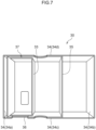
- Fig. 6 is an upper perspective view of a casing 30 serving as part of a configuration of the second element employed in the measurement system 10 of the present exemplary embodiment (see Fig. 11 ).
- Fig. 7 is a bottom view of the casing 30.
- the casing 30 is configured as a paper box having a substantially cuboidal shape with open upper face and lower face.
- the casing 30 of the present exemplary embodiment is provided as a product in a flat-folded state, for assembly as a three-dimensional box as illustrated in the drawing when used.
- the four side faces of the casing 30 configure an external wall section 34 that is vertically upstanding.
- a placement frame 32 that is a frame for placement of a smart device 50 (see Fig.
- the casing 30 serving as a part of the second element is a configuration to which the holder 40 serving as the first element is assembled.
- the four faces of the external wall section 34 include a front face 34a that is a face on which the light blocking section 33 is positioned, a back face 34b that is a face on an opposite side to the front face 34a, a left side face 34c that is a face on a left side when viewed from the front face 34a, and a right side face 34d that is a face on an opposite side to the left side face 34c.
- the interior of the casing 30 is partitioned by a reinforcement portion 35 that is parallel to the front face 34a and the back face 34b.
- a rectangular shaped cut-out portion 36 is also formed at a lower edge of the front side of the left side face 34c.
- a housing area 37 there is a gap between the lower edge of the light blocking section 33 and the lower edge of the external wall section 34, and a space surrounded on four sides by the front face 34a, the reinforcement portion 35, the left side face 34c, and the right side face 34d, and having a height corresponding to the gap is referred to as a housing area 37.
- Assembly of the housing 20 illustrated in Fig. 8 is completed by the holder 40 being assembled to the housing area 37 of the casing 30. In this state, the cut-out portion 36 of the casing 30 and the insertion port 41 of the holder 40 are aligned with each other.
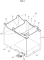
- a state in which the test sample carrier 60 is mounted to the insertion port 41 as illustrated in Fig. 4 and Fig. 5 in this state is as illustrated by the upper perspective view of Fig. 9 .
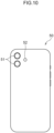
- Fig. 10 is a bottom view of the smart device 50 when employed in the measurement system 10 of the present exemplary embodiment (see Fig. 11 ) in a state placed in the housing 20.
- the configuration resulting from the smart device 50 being placed in the casing 30 is the second element.
- a smartphone is employed as the smart device 50
- a tablet terminal with a camera function may be employed as the smart device 50.
- An imaging section 51 configured by (comprising) a camera, and an illuminator 52 configured by (comprising) a flash that radiates visible light in cooperation therewith, are provided at a bottom face side (so-called back face) of the smart device 50.
- the top face side (so-called front face) of the smart device 50 is configured by a display 53.
- the illuminator 52 radiates a verification area 90 (see Fig. 17 ) of the holder that is the first element when acquiring a verification image described later.
- the smart device 50 illustrated in Fig. 10 is placed with the display 53 facing upward while the imaging section 51 and the illuminator 52 are aligned with the window 31, and thereby the measurement system 10 of the present exemplary embodiment is configured as illustrated in the upper perspective view of Fig. 11 . Entry of external light should be impeded when, from this state, the measurement opening section 43 and the identification opening section 44 of the holder 40 are covered by the light blocking section 33 as illustrated in the upper perspective view of Fig. 12 , which illustrates a state in which the front face 34a, the left side face 34c, and the right side face 34d of the external wall section 34 is supposed to be removed.
- Fig. 12 which illustrates a state in which the front face 34a, the left side face 34c, and the right side face 34d of the external wall section 34 is supposed to be removed.
- extraneous stray light leaks into the interior of the casing 30 due to a way in which the casing 30 is assembled, or due to a mounting fit between the casing 30 and
- the measurement opening section 43 and the filter 45 are positioned above the measurement opening 61 of the test sample carrier 60, and the identification opening section 44 is positioned above the test sample carrier identification region 62.
- the light source 42 is installed below and slightly at the back face side of the identification opening section 44 and radiates from diagonally above the measurement opening 61.
- the window 31 of the casing 30 is positioned directly above the measurement opening section 43, and, as well as the measurement opening section 43, the test sample carrier identification region 62 is also contained in the visual field through this of the imaging section 51 of the smart device 50.
- Fig. 14 illustrates the measurement system 10 of the present exemplary embodiment as a functional block diagram.
- the smart device 50 is provided with the imaging section 51 and the illuminator 52 illustrated in Fig. 10 , and the display 53 illustrated in Fig. 11 , and also with a controller 100 that controls these.
- the controller 100 utilizes a CPU 110, ROM 120, RAM 130, and a storage device 150, described later, as hardware resources of a computer to function as each of the following means.
- the controller 100 functions as an illumination switcher 200 that switches illumination by the illumination section 52 ON/OFF (turn-on/turn-off).
- the illumination switcher 200 may, specifically, be implemented as an application installed on the smart device 50, or alternatively may be implemented as a means that utilizes electrical or optical sensing with the holder 40, or as a wireless communication means (for example, Bluetooth (registered trademark) or the like) with the holder 40.
- the controller 100 functions as an imaging condition storage 210 stored with conditions for capturing with the imaging section 51. Conditions defined as the imaging conditions include, for example, a wait time needed for reaction between the measurement target and the reagent.
- the controller 100 functions as a spot application detector 220 to detect spot application of the test sample on the test sample carrier 60. Moreover, the controller 100 also functions as a wait time measuring unit 230 to measure the wait time. Then, the controller 100 functions as an image storage 240 to store an image of a measurement region 91 (see Fig. 17 ) containing the measurement opening section 43 as captured by the imaging section 51. Furthermore, the controller 100 functions as an analysis section 250 that captures an image of the image captured by the imaging section 51. The imaging section 51 captures the verification area 90 (see Fig.
- the analysis section 250 analyzes the verification image acquired by the imaging section 51, and detects any error after the holder 40 serving as the first element is assembled to the casing 30 serving as the second element, as described later.
- the imaging section 51 and the analysis section 250 are provided at the smart device 50 that is included in the second element. Namely, the second element can be said to be equipped with the imaging section 51.
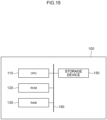
- the controller 100 includes the central processing unit (CPU) 110, the read only memory (ROM) 120, the random access memory (RAM) 130, and the storage device 150. These configurations are each connected together through a bus 190 so as to be capable of communicating with each other.
- CPU central processing unit
- ROM read only memory
- RAM random access memory
- the CPU 110 is a central processing unit that executes various programs and controls each section. Namely, the CPU 110 reads a program from the ROM 120 or the storage device 150, and executes the program using the RAM 130 as a work area. The CPU 110 controls the measurement system 10 according to the program recorded on the ROM 120 or the storage device 150.
- the ROM 120 is stored with various programs and various data.
- the RAM 130 serves as a work area for temporarily storing programs and/or data.
- the storage device 150 is configured as storage by a hard disk drive (HDD), solid state drive (SSD), flash memory, or the like, and stores various programs including an operating system and various data.
- the holder 40 includes the light source 42 that radiates the measurement region 91, the sensor 47 that detects ON/OFF (turn-on/turn-off) of the illuminator 52, and a light source controller 49 that turns the light source 42 on with input with a signal from the sensor 47.
- the light source controller 49 is configured by hardware resources of a computer similarly to the controller 100 of the smart device 50. Note that as long as the light source controller 49 is able to perform control to turn the light source 42 on when capturing the measurement region 91, described later, then the light source controller 49 may be implemented to turn the light source 42 on irrespective of input mode (for example, wired or wireless) of the signal from the sensor 47. Moreover, the light source controller 49 can control to turn the light source 42 off.
- a stray light error is detected by light intensity in, from out of the verification area 90 (see Fig. 17 ), at least one of a check region 97 (see Fig. 24 ) in which extraneous stray light is possible to occur or a specific region 96 (see Fig. 24 ) in which extraneous stray light is likely to occur.
- a stray light error is detected by comparing the light intensity of the at least one of the check region 97 or the specific region 96 against a predetermined threshold.
- a stray light error can be determined when an average value of the light intensity of pixels of the check region 97 or the specific region 96 represented by the image is greater than the predetermined threshold.
- a stray light error can be determined when the number of pixels having light intensity greater than a predetermined threshold is a specific number (for example 10) or greater in the check region 97 or the specific region 96.
- the verification area 90 (see Fig. 17 ) is preferably comprises, in addition to at least the measurement region 91 (see Fig. 17 ), boundary regions 92 (see Fig. 19 ) that are boundaries between the holder 40 serving as the first element and the casing 30 serving as the second element, in a configuration in which, from the verification image described later, the analysis section 250 specifies positions on the image in the verification area 90 (see Fig. 19 ) of at least the boundary regions 92 and detects an assembly error based on the specified positions.
- the measurement system 10 described above is preferably configured with the filter 45 partitioning between the test sample carrier 60 and the imaging section 51 provided in the measurement region 91 (see Fig. 23 ), with errors with the filter 45 detected based on the image information of the filter 45 in the verification image described later.
- Fig. 16 is a flowchart illustrating an overview of error detection in a measurement system of an exemplary embodiment.
- processes executed by a user are indicted in the left column
- processes executed by the illuminator 52 and the imaging section 51 are indicted in the central column
- processes executed by the analysis section 250 are indicated in the right column.
- the user assembles the casing 30 serving as the second element into a three-dimensional box as illustrated in Fig. 6 .
- the housing 20 illustrated in Fig. 8 is assembled by assembling the holder 40 serving as the first element to the casing 30.
- the smart device 50 illustrated in Fig. 10 is placed at the position in the housing 20 illustrated in Fig. 11 .
- illumination of the interior of the casing 30 is performed by the illuminator 52, and imaging is performed by the imaging section 51.
- the illumination switcher 200 of the controller 100 causes a flash of the illuminator 52 to turn on.
- the imaging section 51 images an image, as illustrated in Fig. 17 , of the verification area 90 containing the upper face of the holder 40 and the front face 34a, the left side face 34c, the right side face 34d, and the lower edge portion of the reinforcement portion 35 that surround the upper face of the holder 40 on four sides.
- This image includes the measurement region 91 that is an area in which measurement of the measurement target is performed when the test sample carrier 60 is inserted.
- This image is temporarily stored as a verification image in the RAM 130 or the storage device 150 of the controller 100.
- the analysis section 250 executes a first error detection process indicated by S70 based on the verification image of the verification area 90 illustrated in Fig. 17 .
- the first error detection process is a process to detect an error in the assembly state, and an overview thereof is illustrated in the flowchart illustrated in Fig. 18 .
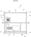
- the boundary regions 92, internal corner regions 93, and the identification region 94 as illustrated in Fig. 19 are specified in the verification area 90 by the analysis section 250.
- the boundary region 92 is specified as a region corresponding to a boundary between the holder 40 serving as the first element and the casing 30 serving as the second element, that is, a region corresponding to the four sides of the holder 40.
- the internal corner regions 93 are specified as regions corresponding to the four corners between adjacent boundary regions of the boundary regions 92.
- the identification region 94 is specified as a region surrounding the identification information 48.
- the analysis section 250 verifies whether or not an inclination of each of the boundary regions 92 falls within a permissible range.
- the boundary regions 92 are configured by pairs of two boundary regions 92 respectively exhibiting a substantially straight line shape that face each other and should be parallel to each other, but they may be configured otherwise depending on how the housing 20 is assembled.
- a numerical range expressing a permissible amount of deviation from such an ideal state is stored as a permissible range in the storage device 150 of the controller 100. Processing transitions to the stage indicated by S75 in cases in which the inclination of the boundary regions 92 is determined not to fall within the permissible range, and an error message stating that assembly is not correct is displayed on the display 53 of the smart device 50 by the controller 100.
- processing proceeds to a stage indicated by S75 in cases in which the position of the identification region 94 was determined not to fall within the permissible range, and an error message stating that assembly is not correct is displayed on the display 53 of the smart device 50 by the controller 100.
- the analysis section 250 executes the second error detection process indicated by S80 of Fig. 16 based on the verification image of the verification area 90 illustrated in Fig. 17 .
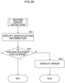
- the second error detection process is a process to detect whether or not the holder 40 serving as the first element is suitable, and an overview thereof is illustrated in the flowchart illustrated in Fig. 20 .
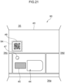
- the identification information 48 illustrated in Fig. 21 is specified inside the verification area 90 by the analysis section 250.
- the analysis section 250 specifies information related to the holder 40 serving as the mounted first element (for example, product number, application, usage limitation, or the like) in the identification information 48 present in the identification region 94.
- processing proceeds to a third error detection process (S90) of Fig. 16 when determined suitable.
- processing proceeds to the stage indicated by S83 when determined unsuitable, and an error message that the holder 40 is unsuitable is displayed on the display 53 of the smart device 50 by the controller 100.
- the analysis section 250 executes the third error detection process indicated by S90 of Fig. 16 based on the verification image of the verification area 90 illustrated in Fig. 17 .
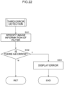
- the third error detection process is a process to detect a filter error 45, and an overview thereof is illustrated in the flowchart illustrated in Fig. 22 .
- image information of the filter 45 is specified by the analysis section 250 based on the image of the measurement region 91 illustrated in Fig. 23 in the verification area 90.
- the illumination switcher 200 of the controller 100 turns off the flash of the illuminator 52.
- the imaging section captures an image of the verification area 90 in a state in which the inside of the casing 30 is a dark chamber as illustrated in Fig. 24 .
- This image includes a permitted region 95 corresponding to the measurement region 91, a specific region 96 corresponding to the boundary between the holder 40 and the reinforcement portion 35, and a check region 97 that is an area of the verification area 90 other than the permitted region 95 and the specific region 96.
- This image is temporarily stored as a verification image in the RAM 130 or the storage device 150 of the controller 100.
- the analysis section 250 executes the fourth error detection process of S100 based on the verification image.
- the fourth abnormality detection process is a process to detect a stray light error, and an overview thereof is illustrated in the flowchart illustrated in Fig. 25 .
- the permitted region 95 illustrated in Fig. 24 is specified inside the verification area 90 by the analysis section 250.
- the permitted region 95 is a region corresponding to the measurement region 91.
- the test sample carrier 60 is not mounted to the holder 40 in a state in which the fourth error detection process is being executed, and so external light sometimes enters the housing section 46 (see Fig. 1 ) through the insertion port 41, and this light is observed in the permitted region 95 as illustrated in Fig. 24 .
- the light observed in the permitted region 95 is not treated as being a target for error detection.
- the specific region 96 illustrated in Fig. 24 is specified in the verification area 90 by the analysis section 250.
- the specific region 96 is a region in which, for example, a gap between the holder 40 serving as the first element and the casing 30 serving as the second element readily occurs as in the boundary region 92 illustrated in Fig. 19 , and is a region in which extraneous stray light readily occurs.
- the analysis section 250 specifies the check region 97 that is an area of the verification area 90 illustrated in Fig. 24 other than the permitted region 95 and the specific region 96.
- a light intensity ratio between the check region 97 and the specific region 96 falls within a permissible range is checked by the analysis section 250. Specifically, the brightness of the data of each pixel configuring (in the image of) the specific region 96 is checked. Next, deviation from the permissible range can be determined in cases in which there are specific number or greater of the specific region 96 pixel data having a brightness of a specific multiple or greater with respect to an average value of the brightness of each pixel data configuring the check region 97.
- Processing proceeds to the stage indicated by S 105 in cases in which the light intensity ratio between the check region 97 and the specific region 96 is determined to not fall within the permissible range, and an error message that there is extraneous stray light is displayed on the display 53 of the smart device 50 by the controller 100.
- test sample carrier 60 is mounted to the housing 20, and measurement of the measurement target in the sample is executed by the measurement system 10, but detailed explanation thereof is omitted herein.
- the present invention is applicable to a measurement system that optically measures a measurement target.
Landscapes
- Health & Medical Sciences (AREA)
- Immunology (AREA)
- Life Sciences & Earth Sciences (AREA)
- Chemical & Material Sciences (AREA)
- Physics & Mathematics (AREA)
- Engineering & Computer Science (AREA)
- Pathology (AREA)
- Biochemistry (AREA)
- General Health & Medical Sciences (AREA)
- General Physics & Mathematics (AREA)
- Analytical Chemistry (AREA)
- Molecular Biology (AREA)
- Hematology (AREA)
- Urology & Nephrology (AREA)
- Biomedical Technology (AREA)
- Plasma & Fusion (AREA)
- Chemical Kinetics & Catalysis (AREA)
- Cell Biology (AREA)
- Biotechnology (AREA)
- Microbiology (AREA)
- Food Science & Technology (AREA)
- Medicinal Chemistry (AREA)
- Investigating Or Analysing Materials By Optical Means (AREA)
- Investigating, Analyzing Materials By Fluorescence Or Luminescence (AREA)
Abstract
A measurement system (10) including a first element in which a test sample carrier (60) applied with a test sample suspected to contain a measurement target is to be held, a second element to which the first element is assembled, an imaging section (51) capturing a verification area (90) containing a measurement region (91) in which the measurement target in the test sample applied to the test sample carrier (60) is to be positioned in the first element and acquiring a verification image, and an analysis section (250) analyzing the verification image and detecting an assembly error of the first element.
Description
- The present invention relates to a measurement system that optically measures a measurement target.
- A fluoroscopy detection device described in Japanese Patent Application Laid-Open (
JP-A) No. 2007-315772 - In a system configured by an optical measurement device employing an immunochromatogram test strip to perform fluorescent immunochromatography measurement in a dark space, and in which the optical measurement device is assembled by users themselves, it is necessary to check if the device is correctly assembled or if there is extraneous stray light in a measurement area. In such cases, since it is necessary to immediately use an individually sealed ordinary test strip after being opened, it is necessary to check such errors before inserting the test strip into the optical measurement device.
- A measurement system of an aspect of the present invention includes a first element in which a test sample carrier applied with a test sample suspected to contain a measurement target is to be held, a second element to which the first element is assembled, an imaging section capturing a verification area containing a measurement region in which the measurement target in the test sample applied to the test sample carrier is to be positioned in the first element and acquiring a verification image, and an analysis section analyzing the verification image and detecting an assembly error of the first element.
- According to an exemplary embodiment of the present invention, it is possible to check an assembly error in an optical measurement device without inserting a test sample carrier such as a test strip.
- Exemplary embodiments will be described in detail based on the following figures, wherein:
-
Fig. 1 is an upper perspective view of a holder serving as a first element employed in an exemplary embodiment; -
Fig. 2 is a lower perspective view illustrating an enlargement of a vicinity of an insertion port of a holder; -
Fig. 3 is a plan view of a test sample carrier employed in an exemplary embodiment; -
Fig. 4 is an upper perspective view of a state in which a test sample carrier is mounted to a holder; -
Fig. 5 is a plan view of the state inFig. 4 ; -
Fig. 6 is an upper perspective view from above of a casing serving as a second element employed in an exemplary embodiment; -
Fig. 7 is a bottom view of a casing; -
Fig. 8 is an upper perspective view of a housing of an exemplary embodiment; -
Fig. 9 is an upper perspective view from above of a state in which a test sample carrier is mounted to the housing ofFig. 8 ; -
Fig. 10 is a bottom view of a smart device employed in an exemplary embodiment; -
Fig. 11 is an upper perspective view of a measurement system of an exemplary embodiment; -
Fig. 12 is an upper perspective view of a state in which part of an external wall section is removed from the measurement system ofFig. 11 ; -
Fig. 13 illustrates a cross-section taken along XIII-XIII ofFig. 12 ; -
Fig. 14 is a functional block diagram of a measurement system of an exemplary embodiment; -
Fig. 15 illustrates a block diagram of a controller; -
Fig. 16 is a flowchart illustrating an overview of error detection in a measurement system of an exemplary embodiment; -
Fig. 17 illustrates an example of a verification area; -
Fig. 18 is a flowchart illustrating an overview of a first error detection process for detecting assembly error; -
Fig. 19 illustrates positions of boundary regions and an identification region in the verification area; -
Fig. 20 is a flowchart illustrating an overview of a second error detection process for detecting whether or not a first element is suitable; -
Fig. 21 illustrates a specific region for displaying identification information in a verification area; -
Fig. 22 is a flowchart illustrating an overview of a third error detection process for detecting a filter error; -
Fig. 23 illustrates a position of a measurement region in a verification area; -
Fig. 24 illustrates a check region and a permitted region in a verification image captured in a dark chamber; and -
Fig. 25 is a flowchart illustrating an overview of a fourth error detection process for detecting stray light error. - Description follows regarding exemplary embodiments of the present invention, with reference to the drawings. Common reference numerals across the drawings indicate same parts unless explicitly stated otherwise. Moreover, each member and each site as represented in the drawings are merely schematic representations thereof, and sizes and positional relationships of an actual product are not necessarily accurately represented therein.
-
Fig. 1 is an upper perspective view of aholder 40 serving as a first element employed in ameasurement system 10 of the present exemplary embodiment (seeFig. 11 ). Themeasurement system 10 may include aholder 40 such as illustrated inFig. 1 as a member configuring (providing) a housing 20 (seeFig. 8 ). Theholder 40 has a box shape and is formed with two openings, i.e., ameasurement opening section 43 and anidentification opening section 44, in an upper face of theholder 40. Afilter 45 with characteristics described later is fitted into themeasurement opening section 43. Asensor 47 for sensing light is furthermore provided at the upper face of theholder 40. Aninsertion port 41 into which atest sample carrier 60 described later (seeFig. 3 ) is to be inserted opens onto a side face of theholder 40. The interior space of theinsertion port 41 is a space in communication with both themeasurement opening section 43 and theidentification opening section 44, and configures ahousing section 46 that is a space in which a part of thetest sample carrier 60 is housed. Moreover,identification information 48 of theholder 40 serving as a first element is displayed in the vicinity of themeasurement opening section 43 on the upper face of theholder 40 by, for example, a QR code (registered trademark). Theholder 40 serving as a first element is configured such that thetest sample carrier 60 applied with the measurement target is held therein. -
Fig. 2 is a lower perspective view illustrating an enlargement of a vicinity of theinsertion port 41 of theholder 40. Thesensor 47 is provided in the vicinity of themeasurement opening section 43 of thehousing section 46 that is the interior space of theinsertion port 41. Light rays of a wavelength appropriate for imaging the measurement target are radiated from a light source 42 (seeFig. 13 ) provided inside thehousing section 46. Then, thefilter 45 has optical characteristics that suitably transmit only light rays of the wavelength employed for such imaging. -
Fig. 3 is a plan view of thetest sample carrier 60 employed in themeasurement system 10 of the present exemplary embodiment (seeFig. 11 ). Thetest sample carrier 60 of the present exemplary embodiment is formed as a test strip exhibiting a flat bar shaped external profile. Agrip portion 65, an upper face side of which is indented, is formed to one end of thetest sample carrier 60. A user can grip thetest sample carrier 60 by pinching thegrip portion 65 with finger tips. Atest paper 64 having a shape elongated along a length direction of thetest sample carrier 60 is housed inside thetest sample carrier 60. Thetest paper 64 is exposed toward above at two openings formed in the upper face of thetest sample carrier 60. These two openings include a test samplespot application portion 63 near thegrip portion 65, and a measurement opening 61 at which measurement of the measurement target is performed further away from thegrip portion 65. A test samplecarrier identification region 62 recorded with information related to thetest sample carrier 60 is formed at the other end side of thetest sample carrier 60, namely, on the upper face of a location furthest away from thegrip portion 65. Hereafter, a side of thetest sample carrier 60 near thegrip portion 65 is called an "upstream side", and a side thereof near the test samplecarrier identification region 62 is called a "downstream side". Note that thetest sample carrier 60 is not limited to a bar shaped test strip such as illustrated inFig. 3 and, for example, a carrier formed as a plate including a measurement chip or a well may be employed therefor. - The
test paper 64 is a water-absorbent body such as filter paper or is configured by (provided by) coating a water-absorbent layer onto a surface of a synthetic resin substrate. A reaction reagent that reacts with the measurement target to develop a color is applied to thetest paper 64. A test sample suspected to contain the measurement target is spotted onto the test samplespot application portion 63. Examples of the test sample include a liquid sample collected from a living body such as, for example, blood or urine, or a diluted solution of either that is diluted with an appropriate solvent, or a liquid sample in which a solid matter or mucus collected from a living body either is diluted with an appropriate solvent or the like or suspended therein. Examples of the measurement target include a component contained in a liquid sample, or an antigen or the like derived from a foreign microorganism or virus. -
Fig. 4 is an upper perspective view of a state in which thetest sample carrier 60 is mounted to theholder 40. Moreover,Fig. 5 is a plan view illustrating this state. As illustrated inFig. 4 andFig. 5 , thetest sample carrier 60 is inserted downstream side first through theinsertion port 41 and into the interior of thehousing section 46. In this state, as illustrated inFig. 5 , themeasurement opening 61 is positioned in the same flat plane as themeasurement opening section 43 and, moreover, the test samplecarrier identification region 62 is positioned in the same flat plane as theidentification opening section 44. - In this state, when a test sample is spotted onto the test sample
spot application portion 63, the test sample flows in the downstream direction under capillary action of thetest paper 64, such that a control reaction band (not illustrated in the drawings) indicating the spot application of the test sample on themeasurement opening 61 occurs near the downstream side. Furthermore, in a case in which the measurement target is contained in the test sample, a target reaction band (not illustrated in the drawings) having a strength according to the concentration of the measurement target occurs near the upstream side relative to the control reaction band. The target reaction band on thetest paper 64 is positioned at a central portion of themeasurement opening 61, and the control reaction band is positioned at the downstream side outside the central portion. Themeasurement system 10 of the present exemplary embodiment measures a concentration of the measurement target by radiating light emitted from thelight source 42 onto the target reaction band, and measuring the intensity of light generated thereby. The test samplecarrier identification region 62 described above is, for example, recorded with (encoded with) which type oftest paper 64 is housed in thetest sample carrier 60 as identification information that is information related to thetest sample carrier 60. Examples of the identification information include a bar code, a QR code (registered trademark), or the like. -
Fig. 6 is an upper perspective view of acasing 30 serving as part of a configuration of the second element employed in themeasurement system 10 of the present exemplary embodiment (seeFig. 11 ). Moreover,Fig. 7 is a bottom view of thecasing 30. Thecasing 30 is configured as a paper box having a substantially cuboidal shape with open upper face and lower face. Thecasing 30 of the present exemplary embodiment is provided as a product in a flat-folded state, for assembly as a three-dimensional box as illustrated in the drawing when used. The four side faces of thecasing 30 configure anexternal wall section 34 that is vertically upstanding. Aplacement frame 32 that is a frame for placement of a smart device 50 (seeFig. 10 ) described later is formed on the upper face of thecasing 30. Alight blocking section 33 of a box shape having a closed upper face including anopen window 31 and an open lower face (seeFig. 7 ) is formed at one side of the interior of the casing 30 (hereafter referred to as the "front side"). Thecasing 30 serving as a part of the second element is a configuration to which theholder 40 serving as the first element is assembled. - The four faces of the
external wall section 34 include afront face 34a that is a face on which thelight blocking section 33 is positioned, aback face 34b that is a face on an opposite side to thefront face 34a, aleft side face 34c that is a face on a left side when viewed from thefront face 34a, and aright side face 34d that is a face on an opposite side to theleft side face 34c. The interior of thecasing 30 is partitioned by areinforcement portion 35 that is parallel to thefront face 34a and theback face 34b. A rectangular shaped cut-outportion 36 is also formed at a lower edge of the front side of theleft side face 34c. - As illustrated in
Fig. 7 , there is a gap between the lower edge of thelight blocking section 33 and the lower edge of theexternal wall section 34, and a space surrounded on four sides by thefront face 34a, thereinforcement portion 35, theleft side face 34c, and theright side face 34d, and having a height corresponding to the gap is referred to as ahousing area 37. Assembly of thehousing 20 illustrated inFig. 8 is completed by theholder 40 being assembled to thehousing area 37 of thecasing 30. In this state, the cut-outportion 36 of thecasing 30 and theinsertion port 41 of theholder 40 are aligned with each other. A state in which thetest sample carrier 60 is mounted to theinsertion port 41 as illustrated inFig. 4 andFig. 5 in this state is as illustrated by the upper perspective view ofFig. 9 . -
Fig. 10 is a bottom view of thesmart device 50 when employed in themeasurement system 10 of the present exemplary embodiment (seeFig. 11 ) in a state placed in thehousing 20. Herein, the configuration resulting from thesmart device 50 being placed in thecasing 30 is the second element. Although, in the present exemplary embodiment, a smartphone is employed as thesmart device 50, a tablet terminal with a camera function may be employed as thesmart device 50. Animaging section 51 configured by (comprising) a camera, and anilluminator 52 configured by (comprising) a flash that radiates visible light in cooperation therewith, are provided at a bottom face side (so-called back face) of thesmart device 50. Note that the top face side (so-called front face) of thesmart device 50 is configured by adisplay 53. Theilluminator 52 radiates a verification area 90 (seeFig. 17 ) of the holder that is the first element when acquiring a verification image described later. - At the inside of the
placement frame 32 of thehousing 20 illustrated inFig. 9 , thesmart device 50 illustrated inFig. 10 is placed with thedisplay 53 facing upward while theimaging section 51 and theilluminator 52 are aligned with thewindow 31, and thereby themeasurement system 10 of the present exemplary embodiment is configured as illustrated in the upper perspective view ofFig. 11 . Entry of external light should be impeded when, from this state, themeasurement opening section 43 and theidentification opening section 44 of theholder 40 are covered by thelight blocking section 33 as illustrated in the upper perspective view ofFig. 12 , which illustrates a state in which thefront face 34a, theleft side face 34c, and theright side face 34d of theexternal wall section 34 is supposed to be removed. However, sometimes extraneous stray light leaks into the interior of thecasing 30 due to a way in which thecasing 30 is assembled, or due to a mounting fit between thecasing 30 and theholder 40. A description is given later regarding this point. - Moreover, as illustrated in
Fig. 13 , which illustrates a cross-section taken along line XIII-XIII ofFig. 12 , themeasurement opening section 43 and thefilter 45 are positioned above themeasurement opening 61 of thetest sample carrier 60, and theidentification opening section 44 is positioned above the test samplecarrier identification region 62. Furthermore, thelight source 42 is installed below and slightly at the back face side of theidentification opening section 44 and radiates from diagonally above themeasurement opening 61. Thewindow 31 of thecasing 30 is positioned directly above themeasurement opening section 43, and, as well as themeasurement opening section 43, the test samplecarrier identification region 62 is also contained in the visual field through this of theimaging section 51 of thesmart device 50. -
Fig. 14 illustrates themeasurement system 10 of the present exemplary embodiment as a functional block diagram. Thesmart device 50 is provided with theimaging section 51 and theilluminator 52 illustrated inFig. 10 , and thedisplay 53 illustrated inFig. 11 , and also with acontroller 100 that controls these. Thecontroller 100 utilizes aCPU 110,ROM 120,RAM 130, and astorage device 150, described later, as hardware resources of a computer to function as each of the following means. - Namely, the
controller 100 functions as anillumination switcher 200 that switches illumination by theillumination section 52 ON/OFF (turn-on/turn-off). Theillumination switcher 200 may, specifically, be implemented as an application installed on thesmart device 50, or alternatively may be implemented as a means that utilizes electrical or optical sensing with theholder 40, or as a wireless communication means (for example, Bluetooth (registered trademark) or the like) with theholder 40. Moreover, thecontroller 100 functions as animaging condition storage 210 stored with conditions for capturing with theimaging section 51. Conditions defined as the imaging conditions include, for example, a wait time needed for reaction between the measurement target and the reagent. Moreover, through theimaging section 51 thecontroller 100 functions as aspot application detector 220 to detect spot application of the test sample on thetest sample carrier 60. Moreover, thecontroller 100 also functions as a waittime measuring unit 230 to measure the wait time. Then, thecontroller 100 functions as animage storage 240 to store an image of a measurement region 91 (seeFig. 17 ) containing themeasurement opening section 43 as captured by theimaging section 51. Furthermore, thecontroller 100 functions as ananalysis section 250 that captures an image of the image captured by theimaging section 51. Theimaging section 51 captures the verification area 90 (seeFig. 17 ) containing themeasurement region 91 in which the measurement target in the test sample applied to thetest sample carrier 60 is to be positioned in theholder 40 serving as the first element, and acquires a verification image described later. Moreover, theanalysis section 250 analyzes the verification image acquired by theimaging section 51, and detects any error after theholder 40 serving as the first element is assembled to thecasing 30 serving as the second element, as described later. In other words, theimaging section 51 and theanalysis section 250 are provided at thesmart device 50 that is included in the second element. Namely, the second element can be said to be equipped with theimaging section 51. - As illustrated by the hardware configuration of
Fig. 15 , thecontroller 100 includes the central processing unit (CPU) 110, the read only memory (ROM) 120, the random access memory (RAM) 130, and thestorage device 150. These configurations are each connected together through abus 190 so as to be capable of communicating with each other. - The
CPU 110 is a central processing unit that executes various programs and controls each section. Namely, theCPU 110 reads a program from theROM 120 or thestorage device 150, and executes the program using theRAM 130 as a work area. TheCPU 110 controls themeasurement system 10 according to the program recorded on theROM 120 or thestorage device 150. - The
ROM 120 is stored with various programs and various data. TheRAM 130 serves as a work area for temporarily storing programs and/or data. Thestorage device 150 is configured as storage by a hard disk drive (HDD), solid state drive (SSD), flash memory, or the like, and stores various programs including an operating system and various data. - The
holder 40 includes thelight source 42 that radiates themeasurement region 91, thesensor 47 that detects ON/OFF (turn-on/turn-off) of theilluminator 52, and alight source controller 49 that turns thelight source 42 on with input with a signal from thesensor 47. Thelight source controller 49 is configured by hardware resources of a computer similarly to thecontroller 100 of thesmart device 50. Note that as long as thelight source controller 49 is able to perform control to turn thelight source 42 on when capturing themeasurement region 91, described later, then thelight source controller 49 may be implemented to turn thelight source 42 on irrespective of input mode (for example, wired or wireless) of the signal from thesensor 47. Moreover, thelight source controller 49 can control to turn thelight source 42 off. - In the
measurement system 10 described above, based on the verification image described later that was captured in a state in which thecasing 30 serving as the second element configured (provided) a dark chamber, a stray light error is detected by light intensity in, from out of the verification area 90 (seeFig. 17 ), at least one of a check region 97 (seeFig. 24 ) in which extraneous stray light is possible to occur or a specific region 96 (seeFig. 24 ) in which extraneous stray light is likely to occur. In addition, in themeasurement system 10 described above, in a state in which thecasing 30 serving as the second element configures a dark chamber, preferably a stray light error is detected by comparing the light intensity of the at least one of thecheck region 97 or thespecific region 96 against a predetermined threshold. For example, a stray light error can be determined when an average value of the light intensity of pixels of thecheck region 97 or thespecific region 96 represented by the image is greater than the predetermined threshold. Alternatively, a stray light error can be determined when the number of pixels having light intensity greater than a predetermined threshold is a specific number (for example 10) or greater in thecheck region 97 or thespecific region 96. - Moreover, in the
measurement system 10 described above, the verification area 90 (seeFig. 17 ) is preferably comprises, in addition to at least the measurement region 91 (seeFig. 17 ), boundary regions 92 (seeFig. 19 ) that are boundaries between theholder 40 serving as the first element and thecasing 30 serving as the second element, in a configuration in which, from the verification image described later, theanalysis section 250 specifies positions on the image in the verification area 90 (seeFig. 19 ) of at least theboundary regions 92 and detects an assembly error based on the specified positions. In such cases, in themeasurement system 10 described above, it is more preferable that there is an identification region 94 (seeFig. 19 ) displayed with theidentification information 48 of theholder 40 serving as the first element inside theverification area 90, and an assembly error is detected based on the position in the image of theidentification region 94 in theverification area 90, and, furthermore, it is more preferable to detect whether or not theholder 40 serving as the first element is suitable based on a content of theidentification information 48. - Furthermore, the
measurement system 10 described above is preferably configured with thefilter 45 partitioning between thetest sample carrier 60 and theimaging section 51 provided in the measurement region 91 (seeFig. 23 ), with errors with thefilter 45 detected based on the image information of thefilter 45 in the verification image described later. - Description follows regarding examples of detection of assembly error using the
measurement system 10 of the present exemplary embodiment, with reference to the flowcharts ofFig. 16 ,Fig. 18 ,Fig. 20 ,Fig. 22 , andFig. 25 , and with reference to the schematic diagrams of theverification area 90 ofFig. 17 ,Fig. 19 ,Fig. 21 ,Fig. 23 , andFig. 24 . -
Fig. 16 is a flowchart illustrating an overview of error detection in a measurement system of an exemplary embodiment. In the three vertically partitioned columns in this figure, processes executed by a user are indicted in the left column, processes executed by theilluminator 52 and theimaging section 51 are indicted in the central column, and processes executed by theanalysis section 250 are indicated in the right column. - Firstly, in the process indicated by S10, the user assembles the
casing 30 serving as the second element into a three-dimensional box as illustrated inFig. 6 . Then, thehousing 20 illustrated inFig. 8 is assembled by assembling theholder 40 serving as the first element to thecasing 30. Then, in a state in which thetest sample carrier 60 is not mounted to theholder 40, thesmart device 50 illustrated inFig. 10 is placed at the position in thehousing 20 illustrated inFig. 11 . In the process indicated by S20, by the user operating thesmart device 50 in this state, illumination of the interior of thecasing 30 is performed by theilluminator 52, and imaging is performed by theimaging section 51. - Namely, in the process indicated by S30, the
illumination switcher 200 of the controller 100 (seeFig. 14 ) causes a flash of theilluminator 52 to turn on. At the same time as the flash illumination, in the process indicated by S40 theimaging section 51 images an image, as illustrated inFig. 17 , of theverification area 90 containing the upper face of theholder 40 and thefront face 34a, theleft side face 34c, theright side face 34d, and the lower edge portion of thereinforcement portion 35 that surround the upper face of theholder 40 on four sides. This image includes themeasurement region 91 that is an area in which measurement of the measurement target is performed when thetest sample carrier 60 is inserted. This image is temporarily stored as a verification image in theRAM 130 or thestorage device 150 of thecontroller 100. - Next, the
analysis section 250 executes a first error detection process indicated by S70 based on the verification image of theverification area 90 illustrated inFig. 17 . The first error detection process is a process to detect an error in the assembly state, and an overview thereof is illustrated in the flowchart illustrated inFig. 18 . - First, at a stage indicated by S71, the
boundary regions 92,internal corner regions 93, and theidentification region 94 as illustrated inFig. 19 are specified in theverification area 90 by theanalysis section 250. Herein, theboundary region 92 is specified as a region corresponding to a boundary between theholder 40 serving as the first element and thecasing 30 serving as the second element, that is, a region corresponding to the four sides of theholder 40. Moreover, theinternal corner regions 93 are specified as regions corresponding to the four corners between adjacent boundary regions of theboundary regions 92. Theidentification region 94 is specified as a region surrounding theidentification information 48. - Next, at the stage indicated by S72, the
analysis section 250 verifies whether or not an inclination of each of theboundary regions 92 falls within a permissible range. Ideally, theboundary regions 92 are configured by pairs of twoboundary regions 92 respectively exhibiting a substantially straight line shape that face each other and should be parallel to each other, but they may be configured otherwise depending on how thehousing 20 is assembled. Thus, a numerical range expressing a permissible amount of deviation from such an ideal state is stored as a permissible range in thestorage device 150 of thecontroller 100. Processing transitions to the stage indicated by S75 in cases in which the inclination of theboundary regions 92 is determined not to fall within the permissible range, and an error message stating that assembly is not correct is displayed on thedisplay 53 of thesmart device 50 by thecontroller 100. - In cases in which the inclinations of the
boundary regions 92 are determined to fall within the permissible range at the stage indicated by S72, verification is performed by theanalysis section 250 at the stage indicated by S73 as to whether or not angles of theinternal corner regions 93 fall within a permissible range. Theinternal corner regions 93 each ideally exhibit a right angle, but may be otherwise due to how thehousing 20 is assembled. Thus, a numerical range expressing a permitted amount of deviation from such an ideal state is stored as a permissible range in thestorage device 150 of thecontroller 100. Processing proceeds to the stage indicated by S75 in cases in which the angles of theinternal corner regions 93 are determined not to fall within the permissible range, and an error message stating that assembly is not correct is displayed on thedisplay 53 of thesmart device 50 by thecontroller 100. - In cases in which the angles of the
internal corner regions 93 are determined to fall within the permissible range at the stage indicated by S73, whether or not the position of theidentification region 94 falls within the permissible range is verified by theanalysis section 250 at the stage indicated by S74. A numerical range expressing a permissible amount of deviation permitted from the position theidentification region 94 should be at in theverification area 90 is stored as a permissible range in thestorage device 150 of thecontroller 100. Processing proceeds to a second error detection process (S80) ofFig. 16 in cases in which the position of theidentification region 94 was determined to fall within the permissible range. On the other hand, processing proceeds to a stage indicated by S75 in cases in which the position of theidentification region 94 was determined not to fall within the permissible range, and an error message stating that assembly is not correct is displayed on thedisplay 53 of thesmart device 50 by thecontroller 100. - In cases in which the position of the
identification region 94 was determined to fall within the permissible range at the stage indicated by S74, theanalysis section 250 executes the second error detection process indicated by S80 ofFig. 16 based on the verification image of theverification area 90 illustrated inFig. 17 . The second error detection process is a process to detect whether or not theholder 40 serving as the first element is suitable, and an overview thereof is illustrated in the flowchart illustrated inFig. 20 . - First, at the stage indicated by S81, the
identification information 48 illustrated inFig. 21 is specified inside theverification area 90 by theanalysis section 250. Specifically, theanalysis section 250 specifies information related to theholder 40 serving as the mounted first element (for example, product number, application, usage limitation, or the like) in theidentification information 48 present in theidentification region 94. - Next, at the stage indicated by S82, whether or not the
holder 40 serving as the mounted first element is suitable for themeasurement system 10 is determined by theanalysis section 250. Processing proceeds to a third error detection process (S90) ofFig. 16 when determined suitable. On the other hand, processing proceeds to the stage indicated by S83 when determined unsuitable, and an error message that theholder 40 is unsuitable is displayed on thedisplay 53 of thesmart device 50 by thecontroller 100. - In cases in which the
holder 40 serving as the first element is determined suitable for themeasurement system 10 at the stage indicated by S82, theanalysis section 250 executes the third error detection process indicated by S90 ofFig. 16 based on the verification image of theverification area 90 illustrated inFig. 17 . The third error detection process is a process to detect afilter error 45, and an overview thereof is illustrated in the flowchart illustrated inFig. 22 . - First, at the stage indicated by S91, image information of the
filter 45 is specified by theanalysis section 250 based on the image of themeasurement region 91 illustrated inFig. 23 in theverification area 90. - Next, at the stage indicated by S92, whether or not there is an error is determined by the
analysis section 250 from the image information of thefilter 45. Assumed examples of such an error include scratches, adhered finger print, or the like. For example, such an error is determined to be present by theanalysis section 250 when there is non-uniform image data in the image information of thefilter 45. Processing proceeds to a fourth error detection process ofFig. 16 (S 100) in cases in which there is no error with thefilter 45. On the other hand, processing proceeds to the stage indicated by S93 in cases in which there is any error with thefilter 45, and an error message that there is an error with thefilter 45 is displayed on thedisplay 53 of thesmart device 50 by thecontroller 100. - After an image is captured in the process indicated by S40 of
Fig. 16 , in the process indicated by S50 theillumination switcher 200 of the controller 100 (seeFig. 14 ) turns off the flash of theilluminator 52. After turning the flash off, in the process indicated by S60 the imaging section captures an image of theverification area 90 in a state in which the inside of thecasing 30 is a dark chamber as illustrated inFig. 24 . This image includes a permittedregion 95 corresponding to themeasurement region 91, aspecific region 96 corresponding to the boundary between theholder 40 and thereinforcement portion 35, and acheck region 97 that is an area of theverification area 90 other than the permittedregion 95 and thespecific region 96. This image is temporarily stored as a verification image in theRAM 130 or thestorage device 150 of thecontroller 100. Theanalysis section 250 executes the fourth error detection process of S100 based on the verification image. The fourth abnormality detection process is a process to detect a stray light error, and an overview thereof is illustrated in the flowchart illustrated inFig. 25 . - First, at the stage indicated by S101 the permitted
region 95 illustrated inFig. 24 is specified inside theverification area 90 by theanalysis section 250. The permittedregion 95 is a region corresponding to themeasurement region 91. Herein, thetest sample carrier 60 is not mounted to theholder 40 in a state in which the fourth error detection process is being executed, and so external light sometimes enters the housing section 46 (seeFig. 1 ) through theinsertion port 41, and this light is observed in the permittedregion 95 as illustrated inFig. 24 . In the fourth error detection process of the present exemplary embodiment the light observed in the permittedregion 95 is not treated as being a target for error detection. - Next, at the stage indicated by S102, the
specific region 96 illustrated inFig. 24 is specified in theverification area 90 by theanalysis section 250. Thespecific region 96 is a region in which, for example, a gap between theholder 40 serving as the first element and thecasing 30 serving as the second element readily occurs as in theboundary region 92 illustrated inFig. 19 , and is a region in which extraneous stray light readily occurs. Then, theanalysis section 250 specifies thecheck region 97 that is an area of theverification area 90 illustrated inFig. 24 other than the permittedregion 95 and thespecific region 96. - Next, at the stage indicated by S103, whether or not the light intensity of the
check region 97 falls within the permissible range is verified by theanalysis section 250. Specifically, a brightness of the data of each pixel configuring (in the image of) thecheck region 97 is checked, whether or not the pixel data has a brightness of a specific value or greater is determined, and also deviation from the permissible range can be determined if such pixel data extends across a fixed number or greater of adjacent pixels. Processing proceeds to the stage indicated byS 105 in cases in which the light intensity of thecheck region 97 is determined not to fall within the permissible range, and an error message that there is extraneous stray light is displayed on thedisplay 53 of thesmart device 50 by thecontroller 100. - Then, at the stage indicated by S 104, whether or not a light intensity ratio between the
check region 97 and thespecific region 96 falls within a permissible range is checked by theanalysis section 250. Specifically, the brightness of the data of each pixel configuring (in the image of) thespecific region 96 is checked. Next, deviation from the permissible range can be determined in cases in which there are specific number or greater of thespecific region 96 pixel data having a brightness of a specific multiple or greater with respect to an average value of the brightness of each pixel data configuring thecheck region 97. Processing proceeds to the stage indicated byS 105 in cases in which the light intensity ratio between thecheck region 97 and thespecific region 96 is determined to not fall within the permissible range, and an error message that there is extraneous stray light is displayed on thedisplay 53 of thesmart device 50 by thecontroller 100. - After any error is not detected by the
analysis section 250 from the first error detection process to the fourth error detection process, thetest sample carrier 60 is mounted to thehousing 20, and measurement of the measurement target in the sample is executed by themeasurement system 10, but detailed explanation thereof is omitted herein. - The present invention is applicable to a measurement system that optically measures a measurement target.
Claims (13)
- A measurement system (10) comprising:a first element in which a test sample carrier (60) applied with a test sample suspected to contain a measurement target is to be held;a second element to which the first element is assembled;an imaging section (51) configured to capture a verification area (90) containing a measurement region (91) in which the measurement target in the test sample applied to the test sample carrier (60) is to be positioned in the first element, and configured to acquire a verification image; andan analysis section (250) configured to analyze the verification image and detect an assembly error of the first element.
- The measurement system (10) of claim 1, wherein a stray light error is detected by light intensity in at least one of a check region (97) or a specific region (96) in the verification area (90), an extraneous stray light being possible to occur in the check region (97) and being likely to occur in the specific region (96), based on the verification image captured in a state in which the second element is a dark chamber.
- The measurement system (10) of claim 2, wherein the stray light error is detected by comparing the light intensity in at least one of the check region (97) or the specific region (96) to a predetermined threshold value in a state in which the second element is a dark chamber.
- The measurement system (10) of any of claim 1 to claim 3, wherein:the verification area (90) includes, in addition to the measurement region (91), at least a boundary region (92) that is a boundary between the first element and the second element; andthe analysis section (250) is configured to specify a position of at least the boundary region (92) in the verification area (90) from the verification image, and is configured to detect the assembly error based on the specified position.
- The measurement system (10) of any of claim 1 to claim 4, wherein:an identification region (94) in which identification information (48) of the first element is indicated is provided in the verification area (90); andthe analysis section (250) is configured to detect the assembly error based on a position in an image of the identification region (94) in the verification area (90).
- The measurement system (10) of any of claim 1 to claim 5, wherein:a filter (45) separating the test sample carrier (60) from the imaging section (51) is provided in the measurement region (91); andthe analysis section (250) is configured to detect a filter error based on image information of the filter (45) in the verification image.
- The measurement system (10) of claim 2, wherein:the verification area (90) includes, in addition to the measurement region (91), at least a boundary region (92) that is a boundary between the first element and the second element; andthe analysis section (250) is configured to, prior to detecting the stray light error, specify a position in an image of at least the boundary region (92) in the verification area (90) from the verification image captured in a state in which the second element is being illuminated by an illuminator, and is configured to detect the assembly error based on the specified position.
- The measurement system (10) of claim 2 or claim 7, wherein:an identification region (94) in which identification information (48) of the first element is indicated is provided in the verification area (90); andthe analysis section (250) is configured to, prior to detecting the stray light error, detect the assembly error based on a position in an image of the verification area (90) in the identification region (94) captured in a state in which the second element is being illuminated by an illuminator.
- The measurement system (10) of claim 5 or claim 8, wherein whether or not the first element is suitable is detected based on a content of the identification information (48).
- The measurement system (10) of claim 2, claim 3, claim 7 or claim 8, wherein:a filter (45) separating the test sample carrier (60) from the imaging section (51) is provided in the measurement region (91); andthe analysis section (250) is configured to, prior to detecting the stray light error, detect a filter error based on image information of the filter (45) in the verification image captured in a state in which the second element is being illuminated by an illuminator (52).
- The measurement system (10) of any of claim 1 to claim 10, wherein the second element includes the imaging section (51).
- The measurement system (10) of any of claim 1 to claim 10, wherein the imaging section (51) and the analysis section (250) are provided at a smart device (50) that is included in the second element.
- The measurement system (10) of any of claim 1 to claim 10, wherein the second element includes a casing (30) and a smart device (50).
Applications Claiming Priority (1)
| Application Number | Priority Date | Filing Date | Title |
|---|---|---|---|
| JP2023185915A JP2025074842A (en) | 2023-10-30 | 2023-10-30 | Measurement System |
Publications (1)
| Publication Number | Publication Date |
|---|---|
| EP4549917A1 true EP4549917A1 (en) | 2025-05-07 |
Family
ID=93288614
Family Applications (1)
| Application Number | Title | Priority Date | Filing Date |
|---|---|---|---|
| EP24209054.6A Pending EP4549917A1 (en) | 2023-10-30 | 2024-10-25 | Measurement system |
Country Status (4)
| Country | Link |
|---|---|
| US (1) | US20250138003A1 (en) |
| EP (1) | EP4549917A1 (en) |
| JP (1) | JP2025074842A (en) |
| CN (1) | CN119915728A (en) |
Citations (7)
| Publication number | Priority date | Publication date | Assignee | Title |
|---|---|---|---|---|
| JP2007315772A (en) | 2006-05-23 | 2007-12-06 | Canon Inc | Fluorescence detection device and biochemical reaction analyzer |
| US20140286550A1 (en) * | 2013-03-21 | 2014-09-25 | Microdiscovery Gmbh | Portable reader module, portable reader, and method for quantitative analysis of an assay |
| US20150233898A1 (en) * | 2014-02-17 | 2015-08-20 | Ixensor Inc. | Measuring physical and biochemical parameters with mobile devices |
| US20170023542A1 (en) * | 2015-07-26 | 2017-01-26 | Naishu Wang | Smartphone dock and diagnostic-test reader plus related methods |
| US20200124587A1 (en) * | 2018-10-19 | 2020-04-23 | Youcount Inc. | Urinalysis device and test strip for home and point of care use |
| KR102297233B1 (en) * | 2019-05-15 | 2021-09-03 | 프리시젼바이오 주식회사 | Immunoassay apparatus |
| US20220065795A1 (en) * | 2019-01-15 | 2022-03-03 | Quidel Corporation | System and methods for remote assessment of a sample assay for disease diagnostics |
-
2023
- 2023-10-30 JP JP2023185915A patent/JP2025074842A/en active Pending
-
2024
- 2024-10-23 CN CN202411481039.XA patent/CN119915728A/en active Pending
- 2024-10-25 EP EP24209054.6A patent/EP4549917A1/en active Pending
- 2024-10-28 US US18/929,520 patent/US20250138003A1/en active Pending
Patent Citations (7)
| Publication number | Priority date | Publication date | Assignee | Title |
|---|---|---|---|---|
| JP2007315772A (en) | 2006-05-23 | 2007-12-06 | Canon Inc | Fluorescence detection device and biochemical reaction analyzer |
| US20140286550A1 (en) * | 2013-03-21 | 2014-09-25 | Microdiscovery Gmbh | Portable reader module, portable reader, and method for quantitative analysis of an assay |
| US20150233898A1 (en) * | 2014-02-17 | 2015-08-20 | Ixensor Inc. | Measuring physical and biochemical parameters with mobile devices |
| US20170023542A1 (en) * | 2015-07-26 | 2017-01-26 | Naishu Wang | Smartphone dock and diagnostic-test reader plus related methods |
| US20200124587A1 (en) * | 2018-10-19 | 2020-04-23 | Youcount Inc. | Urinalysis device and test strip for home and point of care use |
| US20220065795A1 (en) * | 2019-01-15 | 2022-03-03 | Quidel Corporation | System and methods for remote assessment of a sample assay for disease diagnostics |
| KR102297233B1 (en) * | 2019-05-15 | 2021-09-03 | 프리시젼바이오 주식회사 | Immunoassay apparatus |
Also Published As
| Publication number | Publication date |
|---|---|
| JP2025074842A (en) | 2025-05-14 |
| US20250138003A1 (en) | 2025-05-01 |
| CN119915728A (en) | 2025-05-02 |
Similar Documents
| Publication | Publication Date | Title |
|---|---|---|
| EP3548601B1 (en) | Instrument and method for reading a lateral flow assay device | |
| US7444005B2 (en) | Apparatus and method for using optical mouse engine to determine speed, direction, position of scanned device and to obtain quantitative or qualitative data from same | |
| US20250138003A1 (en) | Measurement system | |
| US12529698B2 (en) | Diagnostic testing device and diagnostic testing method | |
| US20240139730A1 (en) | Measurement system | |
| EP2921846B1 (en) | Portable reader module, portable reader, and method for quantitative analysis of an assay | |
| US20230184689A1 (en) | Test strip fixation device for optical measurements of an analyte | |
| US12613193B2 (en) | Measurement system and measurement method | |
| US20240377332A1 (en) | Measurement method and measurement system | |
| US20250137933A1 (en) | Measurement system, measurement method, measurement program, and smart device | |
| US20250377302A1 (en) | Determination system, test strip, and fluorescence reference strip | |
| CA3040527C (en) | Lateral flow assay reader based on human perception and method relating thereto | |
| JP2024163032A (en) | Measurement method and measurement system | |
| JP2024066459A (en) | Measurement System | |
| CN117949382A (en) | Measurement system | |
| HK40070113A (en) | Determination of a concentration of an analyte in a bodily fluid by using a mobile device with a camera | |
| CN114096830A (en) | Determining a concentration of an analyte in a bodily fluid by using a mobile device having a camera |
Legal Events
| Date | Code | Title | Description |
|---|---|---|---|
| PUAI | Public reference made under article 153(3) epc to a published international application that has entered the european phase |
Free format text: ORIGINAL CODE: 0009012 |
|
| STAA | Information on the status of an ep patent application or granted ep patent |
Free format text: STATUS: THE APPLICATION HAS BEEN PUBLISHED |
|
| AK | Designated contracting states |
Kind code of ref document: A1 Designated state(s): AL AT BE BG CH CY CZ DE DK EE ES FI FR GB GR HR HU IE IS IT LI LT LU LV MC ME MK MT NL NO PL PT RO RS SE SI SK SM TR |
|
| STAA | Information on the status of an ep patent application or granted ep patent |
Free format text: STATUS: REQUEST FOR EXAMINATION WAS MADE |
|
| 17P | Request for examination filed |
Effective date: 20251103 |