EP4549881A1 - Systems, apparatuses, and methods to compensate field installation error of a tars device - Google Patents
Systems, apparatuses, and methods to compensate field installation error of a tars device Download PDFInfo
- Publication number
- EP4549881A1 EP4549881A1 EP24203586.3A EP24203586A EP4549881A1 EP 4549881 A1 EP4549881 A1 EP 4549881A1 EP 24203586 A EP24203586 A EP 24203586A EP 4549881 A1 EP4549881 A1 EP 4549881A1
- Authority
- EP
- European Patent Office
- Prior art keywords
- attitude data
- calibration coefficients
- offset error
- vehicle
- tars
- Prior art date
- Legal status (The legal status is an assumption and is not a legal conclusion. Google has not performed a legal analysis and makes no representation as to the accuracy of the status listed.)
- Pending
Links
Images




Classifications
-
- G—PHYSICS
- G01—MEASURING; TESTING
- G01C—MEASURING DISTANCES, LEVELS OR BEARINGS; SURVEYING; NAVIGATION; GYROSCOPIC INSTRUMENTS; PHOTOGRAMMETRY OR VIDEOGRAMMETRY
- G01C25/00—Manufacturing, calibrating, cleaning, or repairing instruments or devices referred to in the other groups of this subclass
-
- B—PERFORMING OPERATIONS; TRANSPORTING
- B60—VEHICLES IN GENERAL
- B60W—CONJOINT CONTROL OF VEHICLE SUB-UNITS OF DIFFERENT TYPE OR DIFFERENT FUNCTION; CONTROL SYSTEMS SPECIALLY ADAPTED FOR HYBRID VEHICLES; ROAD VEHICLE DRIVE CONTROL SYSTEMS FOR PURPOSES NOT RELATED TO THE CONTROL OF A PARTICULAR SUB-UNIT
- B60W30/00—Purposes of road vehicle drive control systems not related to the control of a particular sub-unit, e.g. of systems using conjoint control of vehicle sub-units
- B60W30/18—Propelling the vehicle
- B60W30/182—Selecting between different operative modes, e.g. comfort and performance modes
-
- G—PHYSICS
- G01—MEASURING; TESTING
- G01C—MEASURING DISTANCES, LEVELS OR BEARINGS; SURVEYING; NAVIGATION; GYROSCOPIC INSTRUMENTS; PHOTOGRAMMETRY OR VIDEOGRAMMETRY
- G01C25/00—Manufacturing, calibrating, cleaning, or repairing instruments or devices referred to in the other groups of this subclass
- G01C25/005—Manufacturing, calibrating, cleaning, or repairing instruments or devices referred to in the other groups of this subclass initial alignment, calibration or starting-up of inertial devices
-
- B—PERFORMING OPERATIONS; TRANSPORTING
- B60—VEHICLES IN GENERAL
- B60W—CONJOINT CONTROL OF VEHICLE SUB-UNITS OF DIFFERENT TYPE OR DIFFERENT FUNCTION; CONTROL SYSTEMS SPECIALLY ADAPTED FOR HYBRID VEHICLES; ROAD VEHICLE DRIVE CONTROL SYSTEMS FOR PURPOSES NOT RELATED TO THE CONTROL OF A PARTICULAR SUB-UNIT
- B60W30/00—Purposes of road vehicle drive control systems not related to the control of a particular sub-unit, e.g. of systems using conjoint control of vehicle sub-units
- B60W30/02—Control of vehicle driving stability
-
- B—PERFORMING OPERATIONS; TRANSPORTING
- B60—VEHICLES IN GENERAL
- B60W—CONJOINT CONTROL OF VEHICLE SUB-UNITS OF DIFFERENT TYPE OR DIFFERENT FUNCTION; CONTROL SYSTEMS SPECIALLY ADAPTED FOR HYBRID VEHICLES; ROAD VEHICLE DRIVE CONTROL SYSTEMS FOR PURPOSES NOT RELATED TO THE CONTROL OF A PARTICULAR SUB-UNIT
- B60W40/00—Estimation or calculation of non-directly measurable driving parameters for road vehicle drive control systems not related to the control of a particular sub unit, e.g. by using mathematical models
- B60W40/10—Estimation or calculation of non-directly measurable driving parameters for road vehicle drive control systems not related to the control of a particular sub unit, e.g. by using mathematical models related to vehicle motion
-
- B—PERFORMING OPERATIONS; TRANSPORTING
- B60—VEHICLES IN GENERAL
- B60W—CONJOINT CONTROL OF VEHICLE SUB-UNITS OF DIFFERENT TYPE OR DIFFERENT FUNCTION; CONTROL SYSTEMS SPECIALLY ADAPTED FOR HYBRID VEHICLES; ROAD VEHICLE DRIVE CONTROL SYSTEMS FOR PURPOSES NOT RELATED TO THE CONTROL OF A PARTICULAR SUB-UNIT
- B60W50/00—Details of control systems for road vehicle drive control not related to the control of a particular sub-unit, e.g. process diagnostic or vehicle driver interfaces
- B60W50/08—Interaction between the driver and the control system
- B60W50/082—Selecting or switching between different modes of propelling
-
- E—FIXED CONSTRUCTIONS
- E02—HYDRAULIC ENGINEERING; FOUNDATIONS; SOIL SHIFTING
- E02F—DREDGING; SOIL-SHIFTING
- E02F9/00—Component parts of dredgers or soil-shifting machines, not restricted to one of the kinds covered by groups E02F3/00 - E02F7/00
- E02F9/24—Safety devices, e.g. for preventing overload
-
- G—PHYSICS
- G01—MEASURING; TESTING
- G01C—MEASURING DISTANCES, LEVELS OR BEARINGS; SURVEYING; NAVIGATION; GYROSCOPIC INSTRUMENTS; PHOTOGRAMMETRY OR VIDEOGRAMMETRY
- G01C19/00—Gyroscopes; Turn-sensitive devices using vibrating masses; Turn-sensitive devices without moving masses; Measuring angular rate using gyroscopic effects
- G01C19/005—Measuring angular rate using gyroscopic effects
-
- G—PHYSICS
- G01—MEASURING; TESTING
- G01C—MEASURING DISTANCES, LEVELS OR BEARINGS; SURVEYING; NAVIGATION; GYROSCOPIC INSTRUMENTS; PHOTOGRAMMETRY OR VIDEOGRAMMETRY
- G01C21/00—Navigation; Navigational instruments not provided for in groups G01C1/00 - G01C19/00
- G01C21/10—Navigation; Navigational instruments not provided for in groups G01C1/00 - G01C19/00 by using measurements of speed or acceleration
- G01C21/12—Navigation; Navigational instruments not provided for in groups G01C1/00 - G01C19/00 by using measurements of speed or acceleration executed aboard the object being navigated; Dead reckoning
- G01C21/16—Navigation; Navigational instruments not provided for in groups G01C1/00 - G01C19/00 by using measurements of speed or acceleration executed aboard the object being navigated; Dead reckoning by integrating acceleration or speed, i.e. inertial navigation
-
- G—PHYSICS
- G01—MEASURING; TESTING
- G01C—MEASURING DISTANCES, LEVELS OR BEARINGS; SURVEYING; NAVIGATION; GYROSCOPIC INSTRUMENTS; PHOTOGRAMMETRY OR VIDEOGRAMMETRY
- G01C9/00—Measuring inclination, e.g. by clinometers, by levels
- G01C9/02—Details
-
- G—PHYSICS
- G01—MEASURING; TESTING
- G01P—MEASURING LINEAR OR ANGULAR SPEED, ACCELERATION, DECELERATION, OR SHOCK; INDICATING PRESENCE, ABSENCE, OR DIRECTION, OF MOVEMENT
- G01P15/00—Measuring acceleration; Measuring deceleration; Measuring shock, i.e. sudden change of acceleration
- G01P15/18—Measuring acceleration; Measuring deceleration; Measuring shock, i.e. sudden change of acceleration in two or more dimensions
-
- B—PERFORMING OPERATIONS; TRANSPORTING
- B60—VEHICLES IN GENERAL
- B60W—CONJOINT CONTROL OF VEHICLE SUB-UNITS OF DIFFERENT TYPE OR DIFFERENT FUNCTION; CONTROL SYSTEMS SPECIALLY ADAPTED FOR HYBRID VEHICLES; ROAD VEHICLE DRIVE CONTROL SYSTEMS FOR PURPOSES NOT RELATED TO THE CONTROL OF A PARTICULAR SUB-UNIT
- B60W50/00—Details of control systems for road vehicle drive control not related to the control of a particular sub-unit, e.g. process diagnostic or vehicle driver interfaces
- B60W2050/0062—Adapting control system settings
- B60W2050/0075—Automatic parameter input, automatic initialising or calibrating means
- B60W2050/0083—Setting, resetting, calibration
-
- B—PERFORMING OPERATIONS; TRANSPORTING
- B60—VEHICLES IN GENERAL
- B60W—CONJOINT CONTROL OF VEHICLE SUB-UNITS OF DIFFERENT TYPE OR DIFFERENT FUNCTION; CONTROL SYSTEMS SPECIALLY ADAPTED FOR HYBRID VEHICLES; ROAD VEHICLE DRIVE CONTROL SYSTEMS FOR PURPOSES NOT RELATED TO THE CONTROL OF A PARTICULAR SUB-UNIT
- B60W2520/00—Input parameters relating to overall vehicle dynamics
- B60W2520/14—Yaw
-
- B—PERFORMING OPERATIONS; TRANSPORTING
- B60—VEHICLES IN GENERAL
- B60W—CONJOINT CONTROL OF VEHICLE SUB-UNITS OF DIFFERENT TYPE OR DIFFERENT FUNCTION; CONTROL SYSTEMS SPECIALLY ADAPTED FOR HYBRID VEHICLES; ROAD VEHICLE DRIVE CONTROL SYSTEMS FOR PURPOSES NOT RELATED TO THE CONTROL OF A PARTICULAR SUB-UNIT
- B60W2520/00—Input parameters relating to overall vehicle dynamics
- B60W2520/16—Pitch
-
- B—PERFORMING OPERATIONS; TRANSPORTING
- B60—VEHICLES IN GENERAL
- B60W—CONJOINT CONTROL OF VEHICLE SUB-UNITS OF DIFFERENT TYPE OR DIFFERENT FUNCTION; CONTROL SYSTEMS SPECIALLY ADAPTED FOR HYBRID VEHICLES; ROAD VEHICLE DRIVE CONTROL SYSTEMS FOR PURPOSES NOT RELATED TO THE CONTROL OF A PARTICULAR SUB-UNIT
- B60W2520/00—Input parameters relating to overall vehicle dynamics
- B60W2520/18—Roll
-
- B—PERFORMING OPERATIONS; TRANSPORTING
- B60—VEHICLES IN GENERAL
- B60Y—INDEXING SCHEME RELATING TO ASPECTS CROSS-CUTTING VEHICLE TECHNOLOGY
- B60Y2200/00—Type of vehicle
- B60Y2200/40—Special vehicles
- B60Y2200/41—Construction vehicles, e.g. graders, excavators
Definitions
- Example embodiments of the present disclosure relate generally to sensors, and more particularly, to systems, apparatuses, and methods to compensate field installation error of a Transportation Attitude Reference System (TARS) device.
- TARS Transportation Attitude Reference System
- TARS Transportation Attitude Reference System
- a TARS device provides critical data about the vehicle's pitch, roll, and yaw angles, which are essential for various applications, including navigation, stability control, and safety systems in aircraft, automobiles, marine vessels, and other modes of transportation.
- a TARS device includes sensors such as accelerometers and gyroscopes to measure and report the vehicle's pitch, roll, and yaw angles accurately.
- the integration of calibrated TARS device onto vehicles is a fundamental step in enhancing safety and precision. The TARS device goes through a factory calibration.
- TARS device when a user mounts the TARS device on the vehicle, an offset error is introduced within TARS device which is the installation mounting error with respect to X, Y, & Z axes.
- a recurring challenge arises due to the installation process, particularly an offset error that may cause the TARS device to not deliver accurate data.
- a system comprising at least one sensor configured to detect attitude data. Further, one or more processors having a memory, are operationally coupled with the at least one sensor. The one or more processors are configured to iteratively adjust an offset error present in attitude data until the attitude data is within a linear region. Each iteration receives, via the at least one sensor, the attitude data, wherein the attitude data includes the offset error and determines a plurality of calibration coefficients based at least on the received attitude data. The plurality of calibration coefficients is determined using a piecewise linear equation. Further, in each iteration the determined plurality of calibration coefficients is applied on the received attitude data. Thereafter, in each iteration, the offset error present in the attitude data is adjusted, based at least on the application of the plurality of calibration coefficients, until the attitude data is within the linear region.
- the attitude data comprises at least one of an angular rate, an acceleration, and an inclination of a vehicle. Further, the attitude data is configured to calculate roll/pitch/yaw (RPY) values to adjust the offset error in the attitude data.
- the one or more processors are further configured to execute one or more functions based at least on one or more commands received from a user. Further, the one or more functions include a reset all function, a set function, and an add function. Further, the reset all function corresponds to clearing the determined plurality of calibration coefficients to 0. Further, the set function corresponds to replacing RPY values with the PGN RPY value. Further, the add function corresponds to updating the RPY values with the plurality of calibration coefficients determined from the detected attitude data.
- the one or more processors are configured to receive a command from a user for switching from a normal mode to a compensation mode to adjust the offset error.
- the normal mode corresponds to detecting the attitude data via the at least one sensor and the compensation mode corresponds to adjusting the offset error present in the attitude data.
- the at least one sensor comprises a 3-axis gyroscope or a 3-axis accelerometer.
- the system corresponds to at least one of Transportation Attitude Reference System (TARS) device mounted over the vehicle.
- TARS Transportation Attitude Reference System
- a method iteratively adjusts an offset error present in attitude data until the attitude data is within a linear region.
- Each iteration comprises steps of receiving, via at least one sensor, attitude data, wherein the attitude data includes the offset error. Further, determining, a plurality of calibration coefficients based at least on the received attitude data using a piecewise linear equation. Further, applying, the determined plurality of calibration coefficients to the received attitude data. Thereafter, adjusting, the offset error present in the attitude data based at least on the application of the plurality of calibration coefficients, until the attitude data is within the linear region.
- the term "comprising” means including but not limited to and should be interpreted in the manner it is typically used in the patent context. Use of broader terms such as comprises, includes, and having should be understood to provide support for narrower terms such as consisting of, consisting essentially of, and comprised substantially of.
- ком ⁇ онент or feature may,” “can,” “could,” “should,” “would,” “preferably,” “possibly,” “typically,” “optionally,” “for example,” “often,” or “might” (or other such language) be included or have a characteristic, that a specific component or feature is not required to be included or to have the characteristic. Such a component or feature may be optionally included in some embodiments or it may be excluded.
- Embodiments may correct an offset error in the attitude data of TARS device after the installation of TARS device on a vehicle.
- Embodiments may calculate attitude data and determine calibration coefficients using piecewise linear equation on the attitude data.
- Embodiments may then apply correction on the calculated attitude data.
- Embodiments may calculate attitude data and determine calibration coefficients repeatedly until the final output is within a linear region, which may be one or more thresholds associated with a specification associated with an application the TARS device 100 is used in. Additionally, embodiments may be integrated into the TARS device installed on a vehicle, to provide robust and reliable system for improved vehicle stability control.
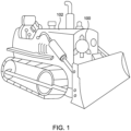
- FIG. 1 illustrates a transportation attitude reference system (TARS) device 100 installed on a vehicle 102 in accordance with an example embodiment of the present disclosure.
- FIG. 2 illustrates a perspective view of an exemplary TARS device 100 in accordance with an example embodiment of the present disclosure.
- FIG. 1 is described in conjunction with FIG. 2 .
- the TARS device 100 may be a packaged sensor array to report attitude data of the vehicle 102.
- the attitude data may include at least an angular rate, an acceleration, and an inclination of the vehicle 102.
- the TARS device 100 may be mounted on, in, or over the vehicle 102.
- the vehicle 102 may be, for example, a forestry vehicle, construction vehicle, pile driver, skid steer loader, mobile crane, smart leveling hitch, wheel loader, excavator vehicles, or any other vehicle known in the art.
- the TARS device 100 may be mounted above the front left tire of a construction vehicle.
- the TARS device 100 may be mounted on the hood of a forestry vehicle.
- the TARS device 100 may be installed, for example, over any fixed part of the vehicle 102 without departing from the scope of the present disclosure.
- the TARS device 100 may be configured to determine the vehicle's pitch, roll, and yaw angles. When a user mounts the TARS device 100 on the vehicle 102 an offset error may be introduced within the TARS device 100.
- the offset error may be an installation mounting error with respect to X, Y, & Z axes.
- the TARS device 100 may be calibrated after installation on the vehicle 102 to compensate and/or reduce the offset error in the attitude data of the TARS device 100, which is described in greater detail herein.
- FIG. 3 illustrates a block diagram of the exemplary TARS device 100 in accordance with an example embodiment of the present disclosure.
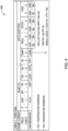
- FIG. 4 illustrates an exemplary table 400 for TARE PGN in accordance with an example embodiment of the present disclosure.
- FIG. 5 illustrates an exemplary table for TARE command in accordance with an example embodiment of the present disclosure.
- FIG. 3 is described in conjunction with FIGS. 4-5 .
- the TARS device 100 may comprise at least one sensor 302, one or more processors 304, a memory 306, input/output circuitry 308, and/or communications circuitry 310.
- a system or apparatus system may be present outside the TARS device 100 and communicatively coupled to the TARS device 100 to perform one or more operations described herein to compensate the field installation error of a TARS device 100.
- the at least one sensor 302 may be configured to detect attitude data of the vehicle 102.
- the at least one sensor 302 may be installed over the vehicle 102.
- the at least one sensor 302 may include, for example, a 3-axis gyroscope and/or a 3-axis accelerometer.
- the attitude data may include an angular rate, an acceleration, and an inclination of the vehicle.
- the angular rate of the vehicle 102 may represent how the angular position or orientation of the vehicle 102 changes with time.
- the angular position or orientation may include how quickly the vehicle 102 rotates around an axis of rotation.
- the angular position or orientation may further include how fast the axis of rotation itself changes direction.
- the 3-axis gyroscope may be used to detect the angular rate of the vehicle 102.
- the acceleration of the vehicle 102 may represent the rate at which the vehicle 102 may increase the speed.
- the 3-axis accelerometer may be used to detect the acceleration of the vehicle 102.
- the inclination of the vehicle 102 may represent an angle between a horizontal plane and a line connecting the vehicle's center of gravity and a point where the tire of the vehicle 102 makes contact with the ground.
- the 3-axis gyroscope sensor in combination with 3-axis accelerometer may be used to detect the inclination of the vehicle 102.
- the detected attitude data may include information on the orientation of the vehicle 102 in three-dimensional space based on the angular rate, the acceleration, and the inclination of the vehicle 102.
- the vehicle's orientation may further include measurements related to the vehicle's roll, pitch, and yaw (RPY) values.
- roll may include the rotation of the vehicle 102 about a longitudinal axis of the vehicle 102.
- the longitudinal axis may include an imaginary line running from the front of the vehicle 102 to the rear of the vehicle 102.
- roll may include the tilting of the vehicle 102 from side to side.
- pitch may include the rotation of the vehicle 102 about a lateral axis of the vehicle 102, which runs from side to side.
- Pitch may include the motion of the vehicle 102 tilting forward and backward.
- yaw may include the rotation of the vehicle 102 about a vertical axis of the vehicle 102, often considered the "up" axis. In some embodiments, yaw may involve the vehicle 102 turning left or right without tilting.
- the at least one sensor 302 may detect the attitude data of the vehicle 102 in real time.
- the attitude data may be calculated at a frequency of 100 hertz (Hz).
- the attitude data may be detected for at periodic intervals.
- the periodic interval may be of 1 minute.
- a low pass filter may be used to remove noise from the detected attitude data.
- a low pass filter of 10 Hz and 3dB cutoff frequency may be used.
- the TARS device 100 may comprise the one or more processors 304.
- the one or more processors 304 may be operationally coupled with the at least one sensor 302.
- the one or more processors 304 may include suitable logic, circuitry, and/or interfaces that are operable to execute one or more instructions stored in the memory 306 to perform predetermined operations.
- the one or more processors 304 may be configured to decode and execute any instructions received from one or more other electronic devices or server(s).
- the one or more processors 304 may be configured to execute one or more computer-readable program instructions, such as program instructions to carry out any of the functions described in this description. Further, the one or more processors 304 may be implemented using one or more processor technologies known in the art.
- processors include, but are not limited to, one or more general purpose processors (e.g., INTEL ® or Advanced Micro Devices ® (AMD) microprocessors) and/or one or more special purpose processors (e.g., digital signal processors or Xilinx ® System On Chip (SOC) Field Programmable Gate Array (FPGA) processor).
- general purpose processors e.g., INTEL ® or Advanced Micro Devices ® (AMD) microprocessors
- special purpose processors e.g., digital signal processors or Xilinx ® System On Chip (SOC) Field Programmable Gate Array (FPGA) processor.
- SOC System On Chip
- FPGA Field Programmable Gate Array
- the memory 306 may store a set of instructions and data.
- the memory 306 may include the one or more instructions that are executable by the one or more processors 304 to perform specific operations. It is apparent to a person with ordinary skill in the art that the one or more instructions stored in the memory 306 enable the hardware of the system 100 to perform the predetermined operations.
- Some of the commonly known memory implementations include, but are not limited to, fixed (hard) drives, magnetic tape, floppy diskettes, optical disks, Compact Disc Read-Only Memories (CD-ROMs), and magneto-optical disks, semiconductor memories, such as ROMs, Random Access Memories (RAMs), Programmable Read-Only Memories (PROMs), Erasable PROMs (EPROMs), Electrically Erasable PROMs (EEPROMs), flash memory, magnetic or optical cards, or other type of media/machine-readable medium suitable for storing electronic instructions.
- RAMs Random Access Memories
- PROMs Programmable Read-Only Memories
- EPROMs Erasable PROMs
- EEPROMs Electrically Erasable PROMs
- flash memory magnetic or optical cards, or other type of media/machine-readable medium suitable for storing electronic instructions.
- the TARS device 100 may include input/output circuitry 308 that may, in turn, be in communication with a processor 304 to receive input from a user and/or output to a user.
- the input/output circuitry 308 may also include additional functionality including a keyboard, a mouse, a joystick, a touch screen, touch areas, soft keys, a microphone, a speaker, or other input/output mechanisms.
- the TARS device 100 may include communications circuitry 310 to communicate with one or more other devices and/or system.
- the communications circuitry 310 may be a device or circuitry embodied in either hardware or a combination of hardware and software that is configured to receive and/or transmit data from/to a network and/or any other device, circuitry, or module in communication with the TARS device 100.
- the communications circuitry 310 may include a plug with multiple terminals that may be connected to another device, apparatus, and/or system.
- the communications circuitry 310 may include, for example, a network interface for enabling communications with a wired or wireless communication network.
- the communications circuitry 310 may include one or more network interface cards, antennae, buses, switches, routers, modems, and supporting hardware and/or software, or any other device suitable for enabling communications via a network.
- the one or more processors 304 may be in communication with a remote device (not shown) via a network interface (not shown) of the communications circuitry 310.
- the network interface may facilitate a communication link between the one or more processors 304 and the remote device. It may be noted that the network interface may further facilitate a communication link among the other components of the TARS device 100.
- the network interface may be a wireless network and/or a wired network.
- the network interface may be implemented using one or more communication techniques.
- the one or more communication techniques may be Radio waves, Wi-Fi, Bluetooth, ZigBee, Z-wave, Visible Light Communication (VLC), Worldwide Interoperability for Microwave Access (WiMAX), Long Term Evolution (LTE), Wireless Local Area Network (WLAN), Infrared (IR) communication, Public Switched Telephone Network (PSTN), Radio waves and other communication techniques, known in the art.
- VLC Visible Light Communication
- WiMAX Worldwide Interoperability for Microwave Access
- LTE Long Term Evolution
- WLAN Wireless Local Area Network
- IR Infrared
- PSTN Public Switched Telephone Network
- the remote device may allow a user to send one or more input commands to the one or more processors 304 to be used with adjusting the offset error present in the detected attitude data.
- the one or more input commands may include or be associated with, but are not limited to, executing one or more functions, calculating the attitude data, determining the plurality of calibration coefficients, providing one or more values for desired attitude data, resetting the plurality of calibration coefficients, or executing a "script" of commands with varying time intervals in between the detecting attitude data or applying the plurality of calibration coefficients.
- the remote device may include a smartphone, a tablet, a laptop, a personal computer (PC), a smart watch or any other computing device known in the art.
- the user may use the smartphone or the tablet as the remote device.
- a dedicated Android or IOS application may be developed to interact with the one or more processors 304. Further, the dedicated application may be used to discover, configure, and/or command the one or more processors 304.
- the one or more processors 304 may be operationally coupled to the at least one senor 302. Further, the one or more processors 304 may be configured to receive, via the at least one sensor, the attitude data. As discussed, the detected attitude data may include information on the orientation of the vehicle in three-dimensional space. The vehicle's orientation may further include measurements related to the vehicle's roll, pitch, and yaw (RPY) values. The one or more processors 304 may be configured to average the received attitude data. Further, the one or more processors 304 may average the received attitude data at the periodic interval. The one or more processors 304 may take average of another received attitude data after the periodic interval. For example, the one or more processors 304 may take average of another received attitude data after 1 minute.
- the one or more processors 304 may be configured to determine a plurality of calibration coefficients based at least on the received attitude data.
- the plurality of calibration coefficients may be determined based at least on the average of the received attitude data.
- the plurality of calibration coefficients may be determined using a piecewise linear equation.
- the piecewise linear equation may be a type of mathematical function that consist of multiple linear segments, each linear segment defined over a specific interval.
- the plurality of calibration coefficients may include coefficients a 0 , a 1 , a 2 of the piecewise linear equation.
- the coefficients a 0 , a 1 , a 2 may be determined based on the average of the detected attitude data.
- a piecewise function may represent a series of multiple linear segments. Further, each linear segment may be defined over specific data sets. To estimate values within the specific data sets, a linear interpolation may be applied to the data sets. Linear interpolation on the data sets may consist of pieces of linear interpolants. Further, linear interpolation on the data sets may include a concatenation of linear interpolants between each pair of the data sets. As a result, a continuous curve may be obtained. Thus, linear interpolation may estimate values within each linear interpolant to represent complex relationships. Further, the one or more processors 304 may be configured to apply the determined plurality of calibration coefficients on the average of the received attitude data. In some embodiments, the one or more processors 304 may apply the determined plurality of calibration coefficients on the vehicle's roll, pitch, and yaw (RPY) values.
- RY yaw
- the one or more processors 304 may be configured to adjust an offset error present in the detected attitude data based at least on the application of the plurality of calibration coefficients. The one or more processors 304 may adjust the offset error until the attitude data is within a linear region of the piecewise linear equation. In some embodiments, the at least one sensor 302 may detect the attitude data and the one or more processors 304 may determine the plurality of calibration coefficients repeatedly, until the attitude data is within a linear region of the piecewise linear equation.
- the offset error may include a constant error present across all measurements of the at least one sensor 302.
- the offset error may be a 'shift' in the output of the at least one sensor 302.
- the at least one sensor 302 may detect the attitude data and the one or more processors 304 may determine the plurality of calibration coefficients repeatedly, until the attitude data is within the linear region of the piecewise linear equation. As a result, the attitude data may come closer to the linear region of the piecewise linear equation and the offset error may reduce with every repetition. Further, the final plurality of calibration coefficients may be stored in the memory 306.
- the remote device may allow the user to send one or more input commands to the one or more processors 304 to adjust the offset error present in the detected attitude data. Further, the one or more processors 304 may receive an input command to execute one or more functions which are described in conjunction with FIG. 4 and FIG. 5 .
- the TARE may be the offset error. It will be apparent to one skilled in the art that the TARE PGN is a peer to peer controller area network (CAN) message as per SAEJ1939 standard.
- the TARE PGN may receive a TARE command as illustrated in FIG. 5 and the information of the detected attitude data.
- the TARE PGN may include the Roll/Pitch/Yaw (RPY) values.
- the table 400 may include the TARE PGN values used in the TARS device 100.
- the table 400 may include a destination address (PS).
- the PS may indicate the address of the system.
- the table 400 may include a requester address (SA).
- SA may indicate the address of the user/the remote device.
- CAN message for each PS and SA may be provided with the number of bits being used in each PS and SA.
- CAN message for roll, pitch, yaw may be provided to calculate the RPY value.
- the table 500 may include TARE command for each roll, pitch, yaw and all of the roll, pitch, yaw.
- Each type of TARE command may include 2 Bits.
- 2 Bits of "ALL” may include BIT ID position of 7 and 6.
- the 2 Bits of "roll” may include bit ID position of 5 and 6.
- the 2 Bits of "pitch” may include bit ID position of 3 and 2.
- the 2 Bits of "yaw” may include bit ID position of 1 and 0.
- the CAN message may include one or more functions.
- the one or more processors 304 may receive the TARE command to execute the one or more functions.
- the one or more functions may further include 00B, 01B, 10B and 11B.
- the 00B CAN message may include a function of "no action”.
- the 01B CAN message may include a function of "reset all” or "set all”.
- the 10B CAN message may include a function of "add”.
- the 11B CAN message may include a function of "reserved”.
- the reset all function may correspond to clearing the determined plurality of calibration coefficients to 0.
- the set function may correspond to replacing RPY values with the PGN RPY value, such as described herein.
- the add function may correspond to updating the RPY values with the plurality of calibration coefficients determined from the detected attitude data.
- the one or more processors are configured to receive a command from a user for switching from a normal mode to a compensation mode to adjust the offset error.
- the normal mode may correspond to detecting the attitude data via the at least one sensor.
- the compensation mode may correspond to adjusting the offset error present in the attitude data.
- the remote device may include a display to show whether the TARS device 100 is in the normal mode or the compensation mode.
- the TARS device 100 may correspond to at least one of Transportation Attitude Reference System (TARS) device 100 mounted over the vehicle 102.
- TARS device 100 may correspond to at least one of Transportation Attitude Reference System (TARS) device 100 mounted over the vehicle 102.
- the detection of the attitude data and execution of further processing steps may be performed by the one or more processors of the TARS device 100 using the at least one sensor 302 without departing from the scope of the disclosure.
- TARS device 100 The above-mentioned components of the TARS device 100 have been provided only for illustration purposes.
- FIG. 6 illustrates a flowchart of an exemplary method 600 to compensate field installation error of the TARS device 100 in accordance with an example embodiment of the present disclosure.
- the method 600 iteratively adjust an offset error present in attitude data until the attitude data is within a linear region, wherein each iteration comprises:
- the attitude data includes the offset error.
- the at least one sensor 302 may be installed over the vehicle to detect attitude data. Further, the at least one sensor 302 may detect the attitude data in real-time.
- the attitude data may include the angular rate, the acceleration, and the inclination of the vehicle. Further, roll/pitch/yaw (RPY) values are detected from the attitude data. Further, the at least one sensor 302 may include at least the 3-axis gyroscope, the 3-axis accelerometer. Further, the average of the detected attitude data may be taken.
- the vehicle 102 is equipped with the at least one sensor 302 i.e. the 3-axis gyroscope and the 3-axis accelerometer works in unison.
- the 3-axis gyroscope reports an angular rate of 30 degrees per second and the 3-axis accelerometer reports an acceleration of 2 meters per second squared, and an inclination of 5 degrees.
- the system 100 determines the plurality of calibration coefficients as 3, 2, 2 based on the angular rate of 30 degrees per second, the acceleration of 2 meters per second squared, and the inclination of 5 degrees.
- the plurality of calibration coefficients may be applied on the average of the detected attitude data.
- the one or more processors 104 applies the determined plurality calibration coefficients 3, 2, 2 to the received attitude data.
- the one or more processors 104 adjusts the angular rate from 30 to 28 degrees per second, acceleration from 2.0 to 1.5 meters per second squared, and the inclination from 5.0 to 4.3 degrees.
- the attitude data may be detected and the plurality of calibration points may be determined repeatedly, until the attitude data is within a linear region.
- the one or more processors 100 adjusts the offset error in the angular rate from 2 degrees per second to 0.3 degrees per second, resulting in highly accurate attitude data.
- the method 600 may further comprise executing, via the one or more processors, one or more functions, based at least on one or more commands received from a user, wherein the one or more functions include a reset all function, a set function, and an add function.
- the reset all function may correspond to clearing the determined plurality of calibration coefficients to 0.
- the set function may correspond to replacing the detected attitude data with average of the detected attitude data at a periodic interval.
- the add function may correspond to updating the detected attitude data with difference between the average attitude data and attitude data detected after the periodic interval.
- the method 600 may further comprise receiving, via the one or more processors, a command from a user for switching from a normal mode to a compensation mode to adjust the offset error.
- the normal mode may correspond to detecting the attitude data via the at least one sensor.
- the compensation mode may correspond to adjusting the offset error present in the attitude data.
- FIG. 7 illustrates a flowchart of an exemplary method 700 to compensate field installation error of the TARS device 100 in accordance with an example embodiment of the present disclosure.
- FIG. 7 is described in conjunction with FIG. 6 .
- the TARS device 100 is mounted on the vehicle 102 at a required location, at step 702.
- the vehicle 102 may be, for example, a forestry vehicle, construction vehicle, pile driver, skid steer loader, mobile crane, smart leveling hitch, wheel loader, excavator vehicles, or any other vehicle known in the art.
- the TARS device 100 may be mounted above the front left tire of a construction vehicle.
- the vehicle 102 is moved relatively to a flat platform (not shown) as seen as the TARS device 100, at step 704. Further, the vehicle 102 may be moved relatively to the flat platform for the TARS device 100 to detect attitude data. The vehicle may be moved either in forward direction or in backward direction.
- attitude data at 200 Hz with low pass filter of 10 Hz is detected and an average of the detected attitude data (inclination) data is calculated, at step 710.
- the attitude data may be detected by the at least one sensor 302 as explained in step 602.
- the attitude data may include the angular rate, the acceleration, and the inclination of the vehicle 102. Further, an average may be taken of the detected attitude data.
- a plurality of calibration coefficients is determined by using a piecewise linear equation, at step 712. Further, the plurality of calibration coefficients may be determined on the average of the detected attitude data as explained in step 604. Successively, another attitude data (inclination) at 200 Hz with low pass filter of 10 Hz is detected and an average of the detected attitude data (inclination) data is calculated, at step 714. Further, more attitude data may be detected and average may be taken of the detected another attitude data. Further, the determined plurality of calibration coefficients may be applied on the detected attitude data as explained in step 602.
- the attitude data may be detected and the plurality of calibration points may be determined repeatedly, until the attitude data is within the linear region.
- the plurality of calibration coefficients is discarded, at step 718.
- the plurality of calibration coefficients may be discarded and another plurality of calibration coefficients may be determined.
- a compensation completion status is indicated, at step 720.
- the compensation mode of the TARS device 100 may be completed. Further, the completion status may be displayed on the display of the remote device.
- the method(s) 600, 700 may be implemented by one or more the embodiments disclosed herein, which may be combined or modified as desired or needed. Additionally, the steps in the method(s) 600, 700 may be modified, changed in order, performed differently, performed sequentially, concurrently or simultaneously, or otherwise modified as desired or needed.
- the above-mentioned embodiments of the present disclosure may be executed by the one or more processors 304 of the TARS device 100 and the method(s) 600, 700 using the at least one sensor 302 without departing from the scope of the disclosure.
- FIG. 8 illustrates an exemplary graph associated with a result 800 of a piecewise linear correction of the TARS device 100 in accordance with an example embodiment of the present disclosure.
- attitude data may be detected and the plurality of calibration coefficients may be determined, repeatedly in one or more regions.
- the one or more regions may include 0-60 seconds (s), 60 s-120 s, etc.
- the result 800 may involve finding out the region from the one or more regions to determine the calibration coefficients which results the detected attitude data within the linear region of the piecewise linear equation.
- the linear interpolation may be applied to estimate values to obtain a continuous curve.
- the piecewise linear correction on the detected attitude data may be applied using the linear interpolation.
- plot 802 may indicate the offset error in percentage (%).
- plot 804 may indicate actual inclination output in degrees (deg).
- the actual inclination output may be an output, obtained after applying the plurality of calibration coefficients of the detected attitude data. Without applying offset correction, the offset error on the TARS device 100 installed on the vehicle 102 may be as large as 4% which is +/- 2 deg of inclination error in the detected attitude data.
- a first stage correction 806, at 0 to 60 seconds (s) may result in 2% offset error which is +/- 0.5 deg of the inclination error.
- a second stage correction 808, at 60 s to 120 s may result in 0.1% offset error which is +/- 0.2 deg of the inclination error.
- an inclination offset specification is +/- 0.2 deg.
- the inclination offset specification may be the specification in which the detected attitude data may fall within the linear region of the piecewise linear equation.
- a third stage correction (not shown), at 120 s to 180 s may be applied, and may go on further till 0% offset error may be obtained.
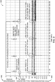
- FIG. 9 illustrates an exemplary simulation result 900 of the TARS device 100 in accordance with an example embodiment of the present disclosure.
- the user may send a command, via the remote device, for switching from a normal mode to a compensation mode to adjust the offset error.
- a compensation status 902 may show up in progress.
- 0 may indicate the normal mode and 3 may indicate the compensation mode.
- the command may put the TARS device 100 into the compensation mode to adjust the offset error in the attitude data.
- the attitude data may be detected repeatedly at a frequency of 200 Hz.
- the attitude data being detected may include a roll inclination 904 and a pitch inclination 906. Further, the roll inclination 904 may be detected in degrees (deg). Further, the pitch inclination 906 may be detected in deg.
- the attitude data may be detected for the periodic interval. For example, the periodic interval may show up every 1 minute.
- the TARS device 100 may average the roll inclination 904 and the pitch inclination 906 at the periodic interval. Further, the low pass filter may be used to remove noise from the average. The average may be considered as first average sample at 0 minute of the compensation status 902. Similarly, another average sample may be obtained. Further, the plurality calibration coefficients may be determined for the of first average sample and another average sample using the piecewise linear equation. Further, a correction may be applied on the determined plurality of calibration coefficients. The correction may be applied in terms of linear interpolation. In one case, if the correction does not fall within the linear region, discard the determined plurality of calibration coefficients may be discarded. And again multiple average samples of attitude data may be obtained at the periodic interval. For example, the periodic interval may show up every 1 minute.
- the mentioned steps in the above embodiment may be repeated until the correction may fall within the linear region. And, the correction may be considered as the final plurality of calibration coefficients and may further be stored in the memory 306. Further, the remote device may indicate the successful compensation sequence 902. As a result, the TARS device 100 may switch back to normal mode from the compensation mode.
Landscapes
- Engineering & Computer Science (AREA)
- Physics & Mathematics (AREA)
- Remote Sensing (AREA)
- Radar, Positioning & Navigation (AREA)
- Automation & Control Theory (AREA)
- General Physics & Mathematics (AREA)
- Transportation (AREA)
- Mechanical Engineering (AREA)
- Manufacturing & Machinery (AREA)
- Structural Engineering (AREA)
- General Engineering & Computer Science (AREA)
- Civil Engineering (AREA)
- Mathematical Physics (AREA)
- Mining & Mineral Resources (AREA)
- Human Computer Interaction (AREA)
- Navigation (AREA)
- User Interface Of Digital Computer (AREA)
Abstract
A system, apparatus, and a method to compensate field installation error of a TARS device is disclosed. An exemplary system comprises at least one sensor configured to detect attitude data and one or more processors having a memory, operationally coupled with the at least one sensor. The one or more processors are configured to iteratively adjust an offset error present in attitude data until attitude data is within a linear region. Each iteration receives, from the at least one sensor, the attitude data and determines a plurality of calibration coefficients based at least on the received attitude data using a piecewise linear equation. The plurality of calibration coefficients are applied to the attitude data. Thereafter, an offset error present in the attitude data is adjusted based at least on application of the plurality of calibration coefficients until the attitude data is within the linear region of the piecewise linear equation.
Description
- Example embodiments of the present disclosure relate generally to sensors, and more particularly, to systems, apparatuses, and methods to compensate field installation error of a Transportation Attitude Reference System (TARS) device.
- Transportation Attitude Reference System (TARS) is a technology used in the field of transportation and vehicle systems to determine and monitor the attitude and/or orientation of a vehicle. For example, a TARS device provides critical data about the vehicle's pitch, roll, and yaw angles, which are essential for various applications, including navigation, stability control, and safety systems in aircraft, automobiles, marine vessels, and other modes of transportation. Typically, a TARS device includes sensors such as accelerometers and gyroscopes to measure and report the vehicle's pitch, roll, and yaw angles accurately. In the domain of transportation and vehicle technology, the integration of calibrated TARS device onto vehicles is a fundamental step in enhancing safety and precision. The TARS device goes through a factory calibration. However, when a user mounts the TARS device on the vehicle, an offset error is introduced within TARS device which is the installation mounting error with respect to X, Y, & Z axes. A recurring challenge arises due to the installation process, particularly an offset error that may cause the TARS device to not deliver accurate data.
- The inventors have identified numerous areas of improvement in the existing technologies and processes, which are the subjects of embodiments described herein. Through applied effort, ingenuity, and innovation, many of these deficiencies, challenges, and problems have been solved by developing solutions that are included in embodiments of the present disclosure, some examples of which are described in detail herein.
- The following presents a summary of some example embodiments to provide a basic understanding of some aspects of the present disclosure. This summary is not an extensive overview and is intended to neither identify key or critical elements nor delineate the scope of such elements. It will also be appreciated that the scope of the disclosure encompasses many potential embodiments in addition to those here summarized, some of which will be further described in the detailed description that is presented later.
- In an example embodiment, a system is disclosed. The system comprises at least one sensor configured to detect attitude data. Further, one or more processors having a memory, are operationally coupled with the at least one sensor. The one or more processors are configured to iteratively adjust an offset error present in attitude data until the attitude data is within a linear region. Each iteration receives, via the at least one sensor, the attitude data, wherein the attitude data includes the offset error and determines a plurality of calibration coefficients based at least on the received attitude data. The plurality of calibration coefficients is determined using a piecewise linear equation. Further, in each iteration the determined plurality of calibration coefficients is applied on the received attitude data. Thereafter, in each iteration, the offset error present in the attitude data is adjusted, based at least on the application of the plurality of calibration coefficients, until the attitude data is within the linear region.
- In some embodiments, the attitude data comprises at least one of an angular rate, an acceleration, and an inclination of a vehicle. Further, the attitude data is configured to calculate roll/pitch/yaw (RPY) values to adjust the offset error in the attitude data. In some embodiments, the one or more processors are further configured to execute one or more functions based at least on one or more commands received from a user. Further, the one or more functions include a reset all function, a set function, and an add function. Further, the reset all function corresponds to clearing the determined plurality of calibration coefficients to 0. Further, the set function corresponds to replacing RPY values with the PGN RPY value. Further, the add function corresponds to updating the RPY values with the plurality of calibration coefficients determined from the detected attitude data.
- In some embodiments, the one or more processors are configured to receive a command from a user for switching from a normal mode to a compensation mode to adjust the offset error. Further, the normal mode corresponds to detecting the attitude data via the at least one sensor and the compensation mode corresponds to adjusting the offset error present in the attitude data.
- In some embodiments, the at least one sensor comprises a 3-axis gyroscope or a 3-axis accelerometer. In some embodiments, the plurality of calibration coefficients comprises coefficients a0, a1, a2 derived from piecewise linear equation

- In another example embodiment, a method is disclosed. The method iteratively adjusts an offset error present in attitude data until the attitude data is within a linear region. Each iteration comprises steps of receiving, via at least one sensor, attitude data, wherein the attitude data includes the offset error. Further, determining, a plurality of calibration coefficients based at least on the received attitude data using a piecewise linear equation. Further, applying, the determined plurality of calibration coefficients to the received attitude data. Thereafter, adjusting, the offset error present in the attitude data based at least on the application of the plurality of calibration coefficients, until the attitude data is within the linear region.
- The above summary is provided merely for purposes of summarizing some example embodiments to provide a basic understanding of some aspects of the present disclosure. Accordingly, it will be appreciated that the above-described embodiments are merely examples and should not be construed to narrow the scope or spirit of the present disclosure in any way. It will be appreciated that the scope of the present disclosure encompasses many potential embodiments in addition to those here summarized, some of which will be further described below.
- Having thus described certain example embodiments of the present disclosure in general terms, reference will hereinafter be made to the accompanying drawings, which are not necessarily drawn to scale, and wherein:
-
FIG. 1 illustrates a transportation attitude reference system (TARS) device installed on a vehicle in accordance with an example embodiment of the present disclosure; -
FIG. 2 illustrates a perspective view of an exemplary TARS device in accordance with an example embodiment of the present disclosure; -
FIG. 3 illustrates a block diagram of an exemplary TARS device in accordance with an example embodiment of the present disclosure; -
FIG. 4 illustrates an exemplary table for TARE PGN in accordance with an example embodiment of the present disclosure; -
FIG. 5 illustrates an exemplary table for TARE command in accordance with an example embodiment of the present disclosure; -
FIG. 6 illustrates a flowchart of an exemplary method to compensate field installation error of the TARS device in accordance with an example embodiment of the present disclosure; -
FIG. 7 illustrates another flowchart of the exemplary method to compensate field installation error of the TARS device in accordance with an example embodiment of the present disclosure; -
FIG. 8 illustrates an exemplary graph associated with a result of a piecewise linear correction of the TARS device in accordance with an example embodiment of the present disclosure; and -
FIG. 9 illustrates an exemplary simulation result of the TARS device in accordance with an example embodiment of the present disclosure. - Some embodiments will now be described more fully hereinafter with reference to the accompanying drawings, in which some, but not all, embodiments of the present disclosure are shown. Indeed, various embodiments may be embodied in many different forms and should not be construed as limited to the embodiments set forth herein; rather, these embodiments are provided so that this disclosure will satisfy applicable legal requirements.
- The components illustrated in the figures represent components that may or may not be present in various embodiments of the present disclosure described herein such that embodiments may include fewer or more components than those shown in the figures while not departing from the scope of the present disclosure. Some components may be omitted from one or more figures or shown in dashed line for visibility of the underlying components.
- As used herein, the term "comprising" means including but not limited to and should be interpreted in the manner it is typically used in the patent context. Use of broader terms such as comprises, includes, and having should be understood to provide support for narrower terms such as consisting of, consisting essentially of, and comprised substantially of.
- The phrases "in various embodiments," "in one embodiment," "according to one embodiment," "in some embodiments," and the like generally mean that the particular feature, structure, or characteristic following the phrase may be included in at least one embodiment of the present disclosure and may be included in more than one embodiment of the present disclosure (importantly, such phrases do not necessarily refer to the same embodiment).
- The word "example" or "exemplary" is used herein to mean "serving as an example, instance, or illustration." Any implementation described herein as "exemplary" is not necessarily to be construed as preferred or advantageous over other implementations.
- If the specification states a component or feature "may," "can," "could," "should," "would," "preferably," "possibly," "typically," "optionally," "for example," "often," or "might" (or other such language) be included or have a characteristic, that a specific component or feature is not required to be included or to have the characteristic. Such a component or feature may be optionally included in some embodiments or it may be excluded.
- The present disclosure provides various embodiments of systems, apparatuses, and methods to compensate field installation error of a Transportation Attitude Reference System (TARS) device. Embodiments may correct an offset error in the attitude data of TARS device after the installation of TARS device on a vehicle. Embodiments may calculate attitude data and determine calibration coefficients using piecewise linear equation on the attitude data. Embodiments may then apply correction on the calculated attitude data. Embodiments may calculate attitude data and determine calibration coefficients repeatedly until the final output is within a linear region, which may be one or more thresholds associated with a specification associated with an application the
TARS device 100 is used in. Additionally, embodiments may be integrated into the TARS device installed on a vehicle, to provide robust and reliable system for improved vehicle stability control. -
FIG. 1 illustrates a transportation attitude reference system (TARS)device 100 installed on avehicle 102 in accordance with an example embodiment of the present disclosure.FIG. 2 illustrates a perspective view of anexemplary TARS device 100 in accordance with an example embodiment of the present disclosure.FIG. 1 is described in conjunction withFIG. 2 . - In some embodiments, the
TARS device 100 may be a packaged sensor array to report attitude data of thevehicle 102. The attitude data may include at least an angular rate, an acceleration, and an inclination of thevehicle 102. Further, theTARS device 100 may be mounted on, in, or over thevehicle 102. In some embodiments, thevehicle 102 may be, for example, a forestry vehicle, construction vehicle, pile driver, skid steer loader, mobile crane, smart leveling hitch, wheel loader, excavator vehicles, or any other vehicle known in the art. In one example embodiment, theTARS device 100 may be mounted above the front left tire of a construction vehicle. In another example embodiment, theTARS device 100 may be mounted on the hood of a forestry vehicle. TheTARS device 100 may be installed, for example, over any fixed part of thevehicle 102 without departing from the scope of the present disclosure. - Further, the
TARS device 100 may be configured to determine the vehicle's pitch, roll, and yaw angles. When a user mounts theTARS device 100 on thevehicle 102 an offset error may be introduced within theTARS device 100. The offset error may be an installation mounting error with respect to X, Y, & Z axes. In some embodiments, theTARS device 100 may be calibrated after installation on thevehicle 102 to compensate and/or reduce the offset error in the attitude data of theTARS device 100, which is described in greater detail herein. -
FIG. 3 illustrates a block diagram of theexemplary TARS device 100 in accordance with an example embodiment of the present disclosure.FIG. 4 illustrates an exemplary table 400 for TARE PGN in accordance with an example embodiment of the present disclosure.FIG. 5 illustrates an exemplary table for TARE command in accordance with an example embodiment of the present disclosure.FIG. 3 is described in conjunction withFIGS. 4-5 . - The
TARS device 100 may comprise at least onesensor 302, one ormore processors 304, amemory 306, input/output circuitry 308, and/orcommunications circuitry 310. In an example embodiment, a system or apparatus system may be present outside theTARS device 100 and communicatively coupled to theTARS device 100 to perform one or more operations described herein to compensate the field installation error of aTARS device 100. - The at least one
sensor 302 may be configured to detect attitude data of thevehicle 102. For example, and in some embodiments, the at least onesensor 302 may be installed over thevehicle 102. The at least onesensor 302 may include, for example, a 3-axis gyroscope and/or a 3-axis accelerometer. In some embodiments, the attitude data may include an angular rate, an acceleration, and an inclination of the vehicle. - The angular rate of the
vehicle 102 may represent how the angular position or orientation of thevehicle 102 changes with time. The angular position or orientation may include how quickly thevehicle 102 rotates around an axis of rotation. The angular position or orientation may further include how fast the axis of rotation itself changes direction. In an example embodiment, the 3-axis gyroscope may be used to detect the angular rate of thevehicle 102. - In some embodiments, the acceleration of the
vehicle 102 may represent the rate at which thevehicle 102 may increase the speed. In an example embodiment, the 3-axis accelerometer may be used to detect the acceleration of thevehicle 102. In some embodiments, the inclination of thevehicle 102 may represent an angle between a horizontal plane and a line connecting the vehicle's center of gravity and a point where the tire of thevehicle 102 makes contact with the ground. In an example embodiment, the 3-axis gyroscope sensor in combination with 3-axis accelerometer may be used to detect the inclination of thevehicle 102. - Further, the detected attitude data may include information on the orientation of the
vehicle 102 in three-dimensional space based on the angular rate, the acceleration, and the inclination of thevehicle 102. The vehicle's orientation may further include measurements related to the vehicle's roll, pitch, and yaw (RPY) values. Further, roll may include the rotation of thevehicle 102 about a longitudinal axis of thevehicle 102. The longitudinal axis may include an imaginary line running from the front of thevehicle 102 to the rear of thevehicle 102. Further, roll may include the tilting of thevehicle 102 from side to side. Further, pitch may include the rotation of thevehicle 102 about a lateral axis of thevehicle 102, which runs from side to side. Pitch may include the motion of thevehicle 102 tilting forward and backward. Further, yaw may include the rotation of thevehicle 102 about a vertical axis of thevehicle 102, often considered the "up" axis. In some embodiments, yaw may involve thevehicle 102 turning left or right without tilting. - In some embodiments, the at least one
sensor 302 may detect the attitude data of thevehicle 102 in real time. In some embodiments, the attitude data may be calculated at a frequency of 100 hertz (Hz). The attitude data may be detected for at periodic intervals. For example, the periodic interval may be of 1 minute. In some embodiments, a low pass filter may be used to remove noise from the detected attitude data. For example, a low pass filter of 10 Hz and 3dB cutoff frequency may be used. - In some embodiments, the
TARS device 100 may comprise the one ormore processors 304. The one ormore processors 304 may be operationally coupled with the at least onesensor 302. In various examples, the one ormore processors 304 may include suitable logic, circuitry, and/or interfaces that are operable to execute one or more instructions stored in thememory 306 to perform predetermined operations. In some embodiments, the one ormore processors 304 may be configured to decode and execute any instructions received from one or more other electronic devices or server(s). The one ormore processors 304 may be configured to execute one or more computer-readable program instructions, such as program instructions to carry out any of the functions described in this description. Further, the one ormore processors 304 may be implemented using one or more processor technologies known in the art. Examples of the processor include, but are not limited to, one or more general purpose processors (e.g., INTEL® or Advanced Micro Devices® (AMD) microprocessors) and/or one or more special purpose processors (e.g., digital signal processors or Xilinx® System On Chip (SOC) Field Programmable Gate Array (FPGA) processor). - The
memory 306 may store a set of instructions and data. In some embodiments, thememory 306 may include the one or more instructions that are executable by the one ormore processors 304 to perform specific operations. It is apparent to a person with ordinary skill in the art that the one or more instructions stored in thememory 306 enable the hardware of thesystem 100 to perform the predetermined operations. Some of the commonly known memory implementations include, but are not limited to, fixed (hard) drives, magnetic tape, floppy diskettes, optical disks, Compact Disc Read-Only Memories (CD-ROMs), and magneto-optical disks, semiconductor memories, such as ROMs, Random Access Memories (RAMs), Programmable Read-Only Memories (PROMs), Erasable PROMs (EPROMs), Electrically Erasable PROMs (EEPROMs), flash memory, magnetic or optical cards, or other type of media/machine-readable medium suitable for storing electronic instructions. - The
TARS device 100 may include input/output circuitry 308 that may, in turn, be in communication with aprocessor 304 to receive input from a user and/or output to a user. In some embodiments, the input/output circuitry 308 may also include additional functionality including a keyboard, a mouse, a joystick, a touch screen, touch areas, soft keys, a microphone, a speaker, or other input/output mechanisms. - The
TARS device 100 may includecommunications circuitry 310 to communicate with one or more other devices and/or system. In some embodiments thecommunications circuitry 310 may be a device or circuitry embodied in either hardware or a combination of hardware and software that is configured to receive and/or transmit data from/to a network and/or any other device, circuitry, or module in communication with theTARS device 100. In some embodiments thecommunications circuitry 310 may include a plug with multiple terminals that may be connected to another device, apparatus, and/or system. In some embodiments, thecommunications circuitry 310 may include, for example, a network interface for enabling communications with a wired or wireless communication network. For example, thecommunications circuitry 310 may include one or more network interface cards, antennae, buses, switches, routers, modems, and supporting hardware and/or software, or any other device suitable for enabling communications via a network. for example, the one ormore processors 304 may be in communication with a remote device (not shown) via a network interface (not shown) of thecommunications circuitry 310. The network interface may facilitate a communication link between the one ormore processors 304 and the remote device. It may be noted that the network interface may further facilitate a communication link among the other components of theTARS device 100. Further, the network interface may be a wireless network and/or a wired network. The network interface may be implemented using one or more communication techniques. The one or more communication techniques may be Radio waves, Wi-Fi, Bluetooth, ZigBee, Z-wave, Visible Light Communication (VLC), Worldwide Interoperability for Microwave Access (WiMAX), Long Term Evolution (LTE), Wireless Local Area Network (WLAN), Infrared (IR) communication, Public Switched Telephone Network (PSTN), Radio waves and other communication techniques, known in the art. - In some embodiments, the remote device may allow a user to send one or more input commands to the one or
more processors 304 to be used with adjusting the offset error present in the detected attitude data. The one or more input commands may include or be associated with, but are not limited to, executing one or more functions, calculating the attitude data, determining the plurality of calibration coefficients, providing one or more values for desired attitude data, resetting the plurality of calibration coefficients, or executing a "script" of commands with varying time intervals in between the detecting attitude data or applying the plurality of calibration coefficients. - In some embodiments, the remote device may include a smartphone, a tablet, a laptop, a personal computer (PC), a smart watch or any other computing device known in the art. In one embodiment, the user may use the smartphone or the tablet as the remote device. In another embodiment, a dedicated Android or IOS application may be developed to interact with the one or
more processors 304. Further, the dedicated application may be used to discover, configure, and/or command the one ormore processors 304. - As described herein, the one or
more processors 304 may be operationally coupled to the at least onesenor 302. Further, the one ormore processors 304 may be configured to receive, via the at least one sensor, the attitude data. As discussed, the detected attitude data may include information on the orientation of the vehicle in three-dimensional space. The vehicle's orientation may further include measurements related to the vehicle's roll, pitch, and yaw (RPY) values. The one ormore processors 304 may be configured to average the received attitude data. Further, the one ormore processors 304 may average the received attitude data at the periodic interval. The one ormore processors 304 may take average of another received attitude data after the periodic interval. For example, the one ormore processors 304 may take average of another received attitude data after 1 minute. - In some embodiments, the one or
more processors 304 may be configured to determine a plurality of calibration coefficients based at least on the received attitude data. The plurality of calibration coefficients may be determined based at least on the average of the received attitude data. Further, the plurality of calibration coefficients may be determined using a piecewise linear equation. The piecewise linear equation may be a type of mathematical function that consist of multiple linear segments, each linear segment defined over a specific interval. In an example embodiment, the piecewise linear equation may include:
- In some embodiments, in the piecewise linear equation, a piecewise function may represent a series of multiple linear segments. Further, each linear segment may be defined over specific data sets. To estimate values within the specific data sets, a linear interpolation may be applied to the data sets. Linear interpolation on the data sets may consist of pieces of linear interpolants. Further, linear interpolation on the data sets may include a concatenation of linear interpolants between each pair of the data sets. As a result, a continuous curve may be obtained. Thus, linear interpolation may estimate values within each linear interpolant to represent complex relationships. Further, the one or
more processors 304 may be configured to apply the determined plurality of calibration coefficients on the average of the received attitude data. In some embodiments, the one ormore processors 304 may apply the determined plurality of calibration coefficients on the vehicle's roll, pitch, and yaw (RPY) values. - In some embodiments, the one or
more processors 304 may be configured to adjust an offset error present in the detected attitude data based at least on the application of the plurality of calibration coefficients. The one ormore processors 304 may adjust the offset error until the attitude data is within a linear region of the piecewise linear equation. In some embodiments, the at least onesensor 302 may detect the attitude data and the one ormore processors 304 may determine the plurality of calibration coefficients repeatedly, until the attitude data is within a linear region of the piecewise linear equation. - In some embodiments, the offset error may include a constant error present across all measurements of the at least one
sensor 302. The offset error may be a 'shift' in the output of the at least onesensor 302. In one example, if the at least onesensor 302 is supposed to output 24°, but instead outputs 26°, the at least onesensor 302 may have an offset error of 2°. Further, the at least onesensor 302 may detect the attitude data and the one ormore processors 304 may determine the plurality of calibration coefficients repeatedly, until the attitude data is within the linear region of the piecewise linear equation. As a result, the attitude data may come closer to the linear region of the piecewise linear equation and the offset error may reduce with every repetition. Further, the final plurality of calibration coefficients may be stored in thememory 306. - As discussed above, the remote device may allow the user to send one or more input commands to the one or
more processors 304 to adjust the offset error present in the detected attitude data. Further, the one ormore processors 304 may receive an input command to execute one or more functions which are described in conjunction withFIG. 4 andFIG. 5 . - Referring to
FIG. 4 , and in accordance with an example embodiment or the present disclosure, an exemplary table 400 for TARE PGN is illustrated. The TARE may be the offset error. It will be apparent to one skilled in the art that the TARE PGN is a peer to peer controller area network (CAN) message as per SAEJ1939 standard. The TARE PGN may receive a TARE command as illustrated inFIG. 5 and the information of the detected attitude data. The TARE PGN may include the Roll/Pitch/Yaw (RPY) values. The table 400 may include the TARE PGN values used in theTARS device 100. The table 400 may include a destination address (PS). The PS may indicate the address of the system. Further, the table 400 may include a requester address (SA). The SA may indicate the address of the user/the remote device. Further, CAN message for each PS and SA may be provided with the number of bits being used in each PS and SA. - Further, CAN message for roll, pitch, yaw (RPY) may be provided to calculate the RPY value. In some embodiments, the RPY value may be calculated using: uint16 = BH*28 + BL. Further, angle may be calculated in degrees using the calculated uint16. The angle may be calculated using: Angle (deg) = (uint16-215)/100. The angle may indicate the actual output obtained after applying the plurality of calibration coefficients on the detected attitude data.
- Referring to
FIG. 5 , and in accordance with an example embodiment or the present disclosure, an exemplary table 500 of TARE command is illustrated. The table 500 may include TARE command for each roll, pitch, yaw and all of the roll, pitch, yaw. Each type of TARE command may include 2 Bits. Further, 2 Bits of "ALL" may include BIT ID position of 7 and 6. Further, the 2 Bits of "roll" may include bit ID position of 5 and 6. The 2 Bits of "pitch" may include bit ID position of 3 and 2. Further, the 2 Bits of "yaw" may include bit ID position of 1 and 0. - Further, in table 500, the CAN message may include one or more functions. Further, the one or
more processors 304 may receive the TARE command to execute the one or more functions. The one or more functions may further include 00B, 01B, 10B and 11B. The 00B CAN message may include a function of "no action". The 01B CAN message may include a function of "reset all" or "set all". The 10B CAN message may include a function of "add". The 11B CAN message may include a function of "reserved". The reset all function may correspond to clearing the determined plurality of calibration coefficients to 0. The set function may correspond to replacing RPY values with the PGN RPY value, such as described herein. The add function may correspond to updating the RPY values with the plurality of calibration coefficients determined from the detected attitude data. - In various embodiments, the one or more processors are configured to receive a command from a user for switching from a normal mode to a compensation mode to adjust the offset error. The normal mode may correspond to detecting the attitude data via the at least one sensor. The compensation mode may correspond to adjusting the offset error present in the attitude data. The remote device may include a display to show whether the
TARS device 100 is in the normal mode or the compensation mode. Further, theTARS device 100 may correspond to at least one of Transportation Attitude Reference System (TARS)device 100 mounted over thevehicle 102. Thus, the offset error may be adjusted to correctly mount theTARS device 100 over thevehicle 102. - The detection of the attitude data and execution of further processing steps may be performed by the one or more processors of the
TARS device 100 using the at least onesensor 302 without departing from the scope of the disclosure. - The above-mentioned components of the
TARS device 100 have been provided only for illustration purposes. -
FIG. 6 illustrates a flowchart of anexemplary method 600 to compensate field installation error of theTARS device 100 in accordance with an example embodiment of the present disclosure. Themethod 600 iteratively adjust an offset error present in attitude data until the attitude data is within a linear region, wherein each iteration comprises: - At first, receiving, via at least one
sensor 302, attitude data, atstep 602. The attitude data includes the offset error. In some embodiments, the at least onesensor 302 may be installed over the vehicle to detect attitude data. Further, the at least onesensor 302 may detect the attitude data in real-time. In some embodiments, the attitude data may include the angular rate, the acceleration, and the inclination of the vehicle. Further, roll/pitch/yaw (RPY) values are detected from the attitude data. Further, the at least onesensor 302 may include at least the 3-axis gyroscope, the 3-axis accelerometer. Further, the average of the detected attitude data may be taken. - For example, the
vehicle 102 is equipped with the at least onesensor 302 i.e. the 3-axis gyroscope and the 3-axis accelerometer works in unison. The 3-axis gyroscope reports an angular rate of 30 degrees per second and the 3-axis accelerometer reports an acceleration of 2 meters per second squared, and an inclination of 5 degrees. - Successively, determining, a plurality of calibration coefficients based at least on the received attitude data using the piecewise linear equation, at
step 604. In some embodiments, the plurality of calibration coefficients may comprise coefficients a0, a1, a2 derived from piecewise linear equation
- For example, using the one or more processors 104, the
system 100 determines the plurality of calibration coefficients as 3, 2, 2 based on the angular rate of 30 degrees per second, the acceleration of 2 meters per second squared, and the inclination of 5 degrees. - Successively, applying, the determined plurality of calibration coefficients on the received attitude data, at
step 606. Further, the plurality of calibration coefficients may be applied on the average of the detected attitude data. For example, the one or more processors 104 applies the determinedplurality calibration coefficients - Successively, adjusting, the offset error present in the attitude data based at least on the application of the plurality of calibration coefficients, until the attitude data is within the linear region, at
step 608. In some embodiments, the attitude data may be detected and the plurality of calibration points may be determined repeatedly, until the attitude data is within a linear region. For example, the one ormore processors 100 adjusts the offset error in the angular rate from 2 degrees per second to 0.3 degrees per second, resulting in highly accurate attitude data. - In some embodiments, the
method 600 may further comprise executing, via the one or more processors, one or more functions, based at least on one or more commands received from a user, wherein the one or more functions include a reset all function, a set function, and an add function. Further, the reset all function may correspond to clearing the determined plurality of calibration coefficients to 0. Further, the set function may correspond to replacing the detected attitude data with average of the detected attitude data at a periodic interval. Further, the add function may correspond to updating the detected attitude data with difference between the average attitude data and attitude data detected after the periodic interval. - In some embodiments, the
method 600 may further comprise receiving, via the one or more processors, a command from a user for switching from a normal mode to a compensation mode to adjust the offset error. Further, the normal mode may correspond to detecting the attitude data via the at least one sensor. And the compensation mode may correspond to adjusting the offset error present in the attitude data. -
FIG. 7 illustrates a flowchart of anexemplary method 700 to compensate field installation error of theTARS device 100 in accordance with an example embodiment of the present disclosure.FIG. 7 is described in conjunction withFIG. 6 . - At first, the
TARS device 100 is mounted on thevehicle 102 at a required location, atstep 702. In some embodiments, thevehicle 102 may be, for example, a forestry vehicle, construction vehicle, pile driver, skid steer loader, mobile crane, smart leveling hitch, wheel loader, excavator vehicles, or any other vehicle known in the art. In one example, theTARS device 100 may be mounted above the front left tire of a construction vehicle. - Successively, the
vehicle 102 is moved relatively to a flat platform (not shown) as seen as theTARS device 100, atstep 704. Further, thevehicle 102 may be moved relatively to the flat platform for theTARS device 100 to detect attitude data. The vehicle may be moved either in forward direction or in backward direction. - Successively, a compensation command is triggered, at
step 706. In some embodiments, the compensation command or command may be received from the user for switching theTARS device 100 from a normal mode to a compensation mode to adjust the offset error. Successively, a compensation in progress status is indicated, atstep 708. When theTARS device 100 may be switched to compensation mode, the progress status including the compensation may be visible to a user on display of the remote device. - Successively, attitude data (inclination) at 200 Hz with low pass filter of 10 Hz is detected and an average of the detected attitude data (inclination) data is calculated, at
step 710. Further, the attitude data may be detected by the at least onesensor 302 as explained instep 602. In some embodiments, the attitude data may include the angular rate, the acceleration, and the inclination of thevehicle 102. Further, an average may be taken of the detected attitude data. - Successively, a plurality of calibration coefficients is determined by using a piecewise linear equation, at
step 712. Further, the plurality of calibration coefficients may be determined on the average of the detected attitude data as explained instep 604. Successively, another attitude data (inclination) at 200 Hz with low pass filter of 10 Hz is detected and an average of the detected attitude data (inclination) data is calculated, atstep 714. Further, more attitude data may be detected and average may be taken of the detected another attitude data. Further, the determined plurality of calibration coefficients may be applied on the detected attitude data as explained instep 602. - Successively, determine whether the detected attitude data is within a linear region of the piecewise linear equation, at
step 716. In some embodiments, the attitude data may be detected and the plurality of calibration points may be determined repeatedly, until the attitude data is within the linear region. - Successively, the plurality of calibration coefficients is discarded, at
step 718. In one case, if the attitude data may not fall within the linear region, the plurality of calibration coefficients may be discarded and another plurality of calibration coefficients may be determined. Successively, a compensation completion status is indicated, atstep 720. In another case, if the attitude data falls within the linear region, the compensation mode of theTARS device 100 may be completed. Further, the completion status may be displayed on the display of the remote device. Successively, storing the plurality of calibration coefficients in thememory 302, atstep 722. Further, the final plurality of calibration coefficients may be stored in the memory of theTARS device 100. - It will be appreciated that the method(s) 600, 700 may be implemented by one or more the embodiments disclosed herein, which may be combined or modified as desired or needed. Additionally, the steps in the method(s) 600, 700 may be modified, changed in order, performed differently, performed sequentially, concurrently or simultaneously, or otherwise modified as desired or needed.
- The above-mentioned embodiments of the present disclosure may be executed by the one or
more processors 304 of theTARS device 100 and the method(s) 600, 700 using the at least onesensor 302 without departing from the scope of the disclosure. -
FIG. 8 illustrates an exemplary graph associated with aresult 800 of a piecewise linear correction of theTARS device 100 in accordance with an example embodiment of the present disclosure. - In some embodiments, attitude data may be detected and the plurality of calibration coefficients may be determined, repeatedly in one or more regions. Further, the one or more regions may include 0-60 seconds (s), 60 s-120 s, etc. Further, the
result 800 may involve finding out the region from the one or more regions to determine the calibration coefficients which results the detected attitude data within the linear region of the piecewise linear equation. - As discussed herein, the linear interpolation may be applied to estimate values to obtain a continuous curve. The piecewise linear correction on the detected attitude data may be applied using the linear interpolation. In some embodiments,
plot 802 may indicate the offset error in percentage (%). Further,plot 804 may indicate actual inclination output in degrees (deg). In some embodiments, the actual inclination output may be an output, obtained after applying the plurality of calibration coefficients of the detected attitude data. Without applying offset correction, the offset error on theTARS device 100 installed on thevehicle 102 may be as large as 4% which is +/- 2 deg of inclination error in the detected attitude data. - Further, a
first stage correction 806, at 0 to 60 seconds (s) may result in 2% offset error which is +/- 0.5 deg of the inclination error. Further, asecond stage correction 808, at 60 s to 120 s may result in 0.1% offset error which is +/- 0.2 deg of the inclination error. In some embodiments, an inclination offset specification is +/- 0.2 deg. In some embodiments, the inclination offset specification may be the specification in which the detected attitude data may fall within the linear region of the piecewise linear equation. Further, if thesecond stage correction 808 may not get into the Inclination offset Specification, a third stage correction (not shown), at 120 s to 180 s may be applied, and may go on further till 0% offset error may be obtained. -
FIG. 9 illustrates anexemplary simulation result 900 of theTARS device 100 in accordance with an example embodiment of the present disclosure. - In some embodiments, the user may send a command, via the remote device, for switching from a normal mode to a compensation mode to adjust the offset error. Further, after receiving the command, a
compensation status 902 may show up in progress. Further, 0 may indicate the normal mode and 3 may indicate the compensation mode. As a result, the command may put theTARS device 100 into the compensation mode to adjust the offset error in the attitude data. - In some embodiments, the attitude data may be detected repeatedly at a frequency of 200 Hz. The attitude data being detected may include a
roll inclination 904 and apitch inclination 906. Further, theroll inclination 904 may be detected in degrees (deg). Further, thepitch inclination 906 may be detected in deg. The attitude data may be detected for the periodic interval. For example, the periodic interval may show up every 1 minute. - In some embodiments, the
TARS device 100 may average theroll inclination 904 and thepitch inclination 906 at the periodic interval. Further, the low pass filter may be used to remove noise from the average. The average may be considered as first average sample at 0 minute of thecompensation status 902. Similarly, another average sample may be obtained. Further, the plurality calibration coefficients may be determined for the of first average sample and another average sample using the piecewise linear equation. Further, a correction may be applied on the determined plurality of calibration coefficients. The correction may be applied in terms of linear interpolation. In one case, if the correction does not fall within the linear region, discard the determined plurality of calibration coefficients may be discarded. And again multiple average samples of attitude data may be obtained at the periodic interval. For example, the periodic interval may show up every 1 minute. - The mentioned steps in the above embodiment may be repeated until the correction may fall within the linear region. And, the correction may be considered as the final plurality of calibration coefficients and may further be stored in the
memory 306. Further, the remote device may indicate thesuccessful compensation sequence 902. As a result, theTARS device 100 may switch back to normal mode from the compensation mode. - Many modifications and other embodiments of the disclosure set forth herein will come to mind to one skilled in the art to which the present disclosure pertains having the benefit of the teachings presented in the foregoing descriptions and the associated drawings. Therefore, it is to be understood that the present disclosure is not to be limited to the specific embodiments disclosed and that modifications and other embodiments are intended to be included within the scope of the appended claims. Moreover, although the foregoing descriptions and the associated drawings describe example embodiments in the context of certain example combinations of elements and/or functions, it should be appreciated that different combinations of elements and/or functions may be provided by alternative embodiments without departing from the scope of the appended claims. In this regard, for example, different combinations of elements and/or functions than those explicitly described above are also contemplated as may be set forth in some of the appended claims. Although specific terms are employed herein, they are used in a generic and descriptive sense only and not for purposes of limitation.
Claims (15)
- A system comprising:at least one sensor configured to detect attitude data;one or more processors having a memory and operationally coupled with the at least one sensor, wherein the one or more processors are configured to:iteratively adjust an offset error present in attitude data until the attitude data is within a linear region, wherein each iteration comprises:receive, from the at least one sensor, the attitude data, wherein the attitude data includes the offset error;determine a plurality of calibration coefficients based at least on the received attitude data using a piecewise linear equation;apply the determined plurality of calibration coefficients on the received attitude data; andadjust the offset error present in the attitude data based at least on the application of the plurality of calibration coefficients until the attitude data is within the linear region.
- The system of claim 1, wherein the attitude data comprises at least one of an angular rate, an acceleration, and an inclination of a vehicle, wherein the attitude data is configured to calculate roll/pitch/yaw (RPY) values to adjust the offset error in the attitude data.
- The system of claim 2, wherein the one or more processors are further configured to execute one or more functions based at least on one or more commands received from a user, wherein the one or more functions include a reset all function, a set function, and an add function.
- The system of claim 3, wherein the reset all function corresponds to clearing the determined plurality of calibration coefficients to 0.
- The system of claim 3, wherein the set function corresponds to replacing RPY values with a PGN RPY value.
- The system of claim 3, wherein the add function corresponds to updating the RPY values with the plurality of calibration coefficients determined from the detected attitude data.
- The system of claim 1, wherein the one or more processors are configured to receive a command from a user for switching from a normal mode to a compensation mode to adjust the offset error.
- The system of claim 7, wherein the normal mode corresponds to detecting the attitude data via the at least one sensor and the compensation mode corresponds to adjusting the offset error present in the attitude data.
- The system of claim 1, wherein the system corresponds to at least one of Transportation Attitude Reference System (TARS) device mounted over a vehicle.
- A method comprising:
iteratively adjust an offset error present in attitude data until the attitude data is within a linear region, wherein each iteration comprises:receiving, from at least one sensor, attitude data, wherein the attitude data includes the offset error;determining, a plurality of calibration coefficients based at least on the received attitude data using a piecewise linear equation;applying, the determined plurality of calibration coefficients on the received attitude data; andadjusting, the offset error present in the attitude data based at least on the application of the plurality of calibration coefficients, until the attitude data is within the linear region. - The method of claim 10, wherein the attitude data comprises at least one of an angular rate, an acceleration, and an inclination of a vehicle, wherein the attitude data is configured to calculate roll/pitch/yaw (RPY) values to adjust the offset error in the attitude data.
- The method of claim 11, further comprising,
executing one or more functions, based at least on one or more commands received from a user, wherein the one or more functions include a reset all function, a set function, and an add function. - The method of claim 12, wherein the reset all function corresponds to clearing the determined plurality of calibration coefficients to 0.
- The method of claim 12, wherein the set function corresponds to replacing RPY values with a PGN RPY value.
- The method of claim 12, wherein the add function corresponds to updating the RPY values with the plurality of calibration coefficients determined from the detected attitude data.
Applications Claiming Priority (1)
| Application Number | Priority Date | Filing Date | Title |
|---|---|---|---|
| IN202311074461 | 2023-11-01 |
Publications (1)
| Publication Number | Publication Date |
|---|---|
| EP4549881A1 true EP4549881A1 (en) | 2025-05-07 |
Family
ID=92932553
Family Applications (1)
| Application Number | Title | Priority Date | Filing Date |
|---|---|---|---|
| EP24203586.3A Pending EP4549881A1 (en) | 2023-11-01 | 2024-09-30 | Systems, apparatuses, and methods to compensate field installation error of a tars device |
Country Status (5)
| Country | Link |
|---|---|
| US (1) | US20250136117A1 (en) |
| EP (1) | EP4549881A1 (en) |
| JP (1) | JP2025076326A (en) |
| KR (1) | KR20250063739A (en) |
| CN (1) | CN119935122A (en) |
Citations (2)
| Publication number | Priority date | Publication date | Assignee | Title |
|---|---|---|---|---|
| EP2026037A2 (en) * | 2007-08-14 | 2009-02-18 | Honeywell International Inc. | Navigation system and corresponding method for gyrocompass alignment using dynamically calibrated sensor data and an iterative extended kalman filter |
| US20200132462A1 (en) * | 2017-07-18 | 2020-04-30 | Denso Corporation | Sensor calibration device and sensor calibration program product |
Family Cites Families (4)
| Publication number | Priority date | Publication date | Assignee | Title |
|---|---|---|---|---|
| US20030061859A1 (en) * | 2001-01-29 | 2003-04-03 | Ford Global Technologies, Inc. | Accelerometer calibration |
| JP2012237682A (en) * | 2011-05-12 | 2012-12-06 | Fujikura Ltd | Multi-axis sensor output correction device and multi-axis sensor output correction method |
| JP2018040588A (en) * | 2016-09-05 | 2018-03-15 | 株式会社デンソーテン | Method for correcting output from physical sensor and electronic apparatus |
| JP7349009B1 (en) * | 2022-12-26 | 2023-09-21 | 株式会社東陽テクニカ | Position calculation method and position calculation device |
-
2024
- 2024-09-30 EP EP24203586.3A patent/EP4549881A1/en active Pending
- 2024-10-12 CN CN202411421455.0A patent/CN119935122A/en active Pending
- 2024-10-15 JP JP2024179930A patent/JP2025076326A/en active Pending
- 2024-10-17 KR KR1020240141894A patent/KR20250063739A/en active Pending
- 2024-10-18 US US18/920,158 patent/US20250136117A1/en active Pending
Patent Citations (2)
| Publication number | Priority date | Publication date | Assignee | Title |
|---|---|---|---|---|
| EP2026037A2 (en) * | 2007-08-14 | 2009-02-18 | Honeywell International Inc. | Navigation system and corresponding method for gyrocompass alignment using dynamically calibrated sensor data and an iterative extended kalman filter |
| US20200132462A1 (en) * | 2017-07-18 | 2020-04-30 | Denso Corporation | Sensor calibration device and sensor calibration program product |
Non-Patent Citations (1)
| Title |
|---|
| ANONYMOUS: "Piecewise linear function - Wikipedia", 3 October 2023 (2023-10-03), pages 1 - 5, XP093252951, Retrieved from the Internet <URL:https://en.wikipedia.org/w/index.php?title=Piecewise_linear_function&oldid=1178464029> * |
Also Published As
| Publication number | Publication date |
|---|---|
| CN119935122A (en) | 2025-05-06 |
| KR20250063739A (en) | 2025-05-08 |
| US20250136117A1 (en) | 2025-05-01 |
| JP2025076326A (en) | 2025-05-15 |
Similar Documents
| Publication | Publication Date | Title |
|---|---|---|
| EP2452156B1 (en) | Accelerometer system, method and computer program product | |
| US20170010174A1 (en) | Mobile computer atmospheric barometric pressure system | |
| US11148592B2 (en) | Motorcycle driving assistance device | |
| EP2472225B1 (en) | Method and system for initial quaternion and attitude estimation | |
| EP2646777B1 (en) | Inertial sensor aided heading and positioning for gnss vehicle navigation | |
| EP3848730A1 (en) | Positioning method, apparatus and device, and computer-readable storage medium | |
| US10605925B2 (en) | Processing GPS drifting | |
| CN110580186B (en) | Method for calibrating a gradient control system, mobile device and work machine | |
| JP2013535669A (en) | Apparatus and method for calibrating dynamic parameters of a vehicle navigation system | |
| EP2026037A2 (en) | Navigation system and corresponding method for gyrocompass alignment using dynamically calibrated sensor data and an iterative extended kalman filter | |
| WO2017064790A1 (en) | Positioning device and positioning method | |
| JP6815078B2 (en) | How to provide GNSS signal | |
| CN108873043B (en) | Method and device for calculating vehicle sideslip angle | |
| US10612994B2 (en) | Measuring pavement deflections using data from laser scanning sensors as well as from high precision accelerometers and gyrometers | |
| US20180149480A1 (en) | System for incremental trajectory estimation based on real time inertial sensing | |
| US9995019B2 (en) | Estimation with gyros of the relative attitude between a vehicle body and an implement operably coupled to the vehicle body | |
| US20170261336A1 (en) | Accelerometer system and method | |
| JP2004138553A (en) | Moving object position detecting device, moving object position detecting method, program, and recording medium | |
| CN113985466A (en) | Combined navigation method and system based on pattern recognition | |
| KR102625262B1 (en) | Apparatus and method for determine the location of vehicle in GPS shadow area | |
| US20250136117A1 (en) | Systems, apparatuses, and methods to compensate field installation error of a tars device | |
| CN111959409B (en) | Holder adjusting method, storage medium, electronic device and vehicle | |
| JP4629738B2 (en) | Navigation device, method thereof, program thereof and recording medium thereof | |
| JP3331865B2 (en) | Navigation device | |
| CN118182451A (en) | Method and device for determining parking torque, electronic device and storage medium |
Legal Events
| Date | Code | Title | Description |
|---|---|---|---|
| PUAI | Public reference made under article 153(3) epc to a published international application that has entered the european phase |
Free format text: ORIGINAL CODE: 0009012 |
|
| STAA | Information on the status of an ep patent application or granted ep patent |
Free format text: STATUS: REQUEST FOR EXAMINATION WAS MADE |
|
| 17P | Request for examination filed |
Effective date: 20240930 |
|
| AK | Designated contracting states |
Kind code of ref document: A1 Designated state(s): AL AT BE BG CH CY CZ DE DK EE ES FI FR GB GR HR HU IE IS IT LI LT LU LV MC ME MK MT NL NO PL PT RO RS SE SI SK SM TR |
|
| STAA | Information on the status of an ep patent application or granted ep patent |
Free format text: STATUS: EXAMINATION IS IN PROGRESS |
|
| 17Q | First examination report despatched |
Effective date: 20260325 |