EP4549849A1 - Method for controlling a refrigerated transportation system and refrigerated transportation system - Google Patents
Method for controlling a refrigerated transportation system and refrigerated transportation system Download PDFInfo
- Publication number
- EP4549849A1 EP4549849A1 EP24209967.9A EP24209967A EP4549849A1 EP 4549849 A1 EP4549849 A1 EP 4549849A1 EP 24209967 A EP24209967 A EP 24209967A EP 4549849 A1 EP4549849 A1 EP 4549849A1
- Authority
- EP
- European Patent Office
- Prior art keywords
- evaporator
- transportation system
- cold energy
- box
- phase change
- Prior art date
- Legal status (The legal status is an assumption and is not a legal conclusion. Google has not performed a legal analysis and makes no representation as to the accuracy of the status listed.)
- Pending
Links
Images


Classifications
-
- F—MECHANICAL ENGINEERING; LIGHTING; HEATING; WEAPONS; BLASTING
- F25—REFRIGERATION OR COOLING; COMBINED HEATING AND REFRIGERATION SYSTEMS; HEAT PUMP SYSTEMS; MANUFACTURE OR STORAGE OF ICE; LIQUEFACTION SOLIDIFICATION OF GASES
- F25D—REFRIGERATORS; COLD ROOMS; ICE-BOXES; COOLING OR FREEZING APPARATUS NOT OTHERWISE PROVIDED FOR
- F25D11/00—Self-contained movable devices, e.g. domestic refrigerators
- F25D11/003—Transport containers
-
- B—PERFORMING OPERATIONS; TRANSPORTING
- B60—VEHICLES IN GENERAL
- B60H—ARRANGEMENTS OF HEATING, COOLING, VENTILATING OR OTHER AIR-TREATING DEVICES SPECIALLY ADAPTED FOR PASSENGER OR GOODS SPACES OF VEHICLES
- B60H1/00—Heating, cooling or ventilating devices
- B60H1/00642—Control systems or circuits; Control members or indication devices for heating, cooling or ventilating devices
- B60H1/00814—Control systems or circuits characterised by their output, for controlling particular components of the heating, cooling or ventilating installation
- B60H1/00878—Control systems or circuits characterised by their output, for controlling particular components of the heating, cooling or ventilating installation the components being temperature regulating devices
-
- B—PERFORMING OPERATIONS; TRANSPORTING
- B60—VEHICLES IN GENERAL
- B60H—ARRANGEMENTS OF HEATING, COOLING, VENTILATING OR OTHER AIR-TREATING DEVICES SPECIALLY ADAPTED FOR PASSENGER OR GOODS SPACES OF VEHICLES
- B60H1/00—Heating, cooling or ventilating devices
- B60H1/00357—Air-conditioning arrangements specially adapted for particular vehicles
- B60H1/00364—Air-conditioning arrangements specially adapted for particular vehicles for caravans or trailers
-
- B—PERFORMING OPERATIONS; TRANSPORTING
- B60—VEHICLES IN GENERAL
- B60H—ARRANGEMENTS OF HEATING, COOLING, VENTILATING OR OTHER AIR-TREATING DEVICES SPECIALLY ADAPTED FOR PASSENGER OR GOODS SPACES OF VEHICLES
- B60H1/00—Heating, cooling or ventilating devices
- B60H1/00357—Air-conditioning arrangements specially adapted for particular vehicles
- B60H1/00385—Air-conditioning arrangements specially adapted for particular vehicles for vehicles having an electrical drive, e.g. hybrid or fuel cell
-
- B—PERFORMING OPERATIONS; TRANSPORTING
- B60—VEHICLES IN GENERAL
- B60H—ARRANGEMENTS OF HEATING, COOLING, VENTILATING OR OTHER AIR-TREATING DEVICES SPECIALLY ADAPTED FOR PASSENGER OR GOODS SPACES OF VEHICLES
- B60H1/00—Heating, cooling or ventilating devices
- B60H1/00492—Heating, cooling or ventilating devices comprising regenerative heating or cooling means, e.g. heat accumulators
- B60H1/005—Regenerative cooling means, e.g. cold accumulators
-
- B—PERFORMING OPERATIONS; TRANSPORTING
- B60—VEHICLES IN GENERAL
- B60H—ARRANGEMENTS OF HEATING, COOLING, VENTILATING OR OTHER AIR-TREATING DEVICES SPECIALLY ADAPTED FOR PASSENGER OR GOODS SPACES OF VEHICLES
- B60H1/00—Heating, cooling or ventilating devices
- B60H1/32—Cooling devices
- B60H1/3204—Cooling devices using compression
- B60H1/323—Cooling devices using compression characterised by comprising auxiliary or multiple systems, e.g. plurality of evaporators, or by involving auxiliary cooling devices
-
- B—PERFORMING OPERATIONS; TRANSPORTING
- B60—VEHICLES IN GENERAL
- B60H—ARRANGEMENTS OF HEATING, COOLING, VENTILATING OR OTHER AIR-TREATING DEVICES SPECIALLY ADAPTED FOR PASSENGER OR GOODS SPACES OF VEHICLES
- B60H1/00—Heating, cooling or ventilating devices
- B60H1/32—Cooling devices
- B60H1/3204—Cooling devices using compression
- B60H1/3232—Cooling devices using compression particularly adapted for load transporting vehicles
-
- F—MECHANICAL ENGINEERING; LIGHTING; HEATING; WEAPONS; BLASTING
- F25—REFRIGERATION OR COOLING; COMBINED HEATING AND REFRIGERATION SYSTEMS; HEAT PUMP SYSTEMS; MANUFACTURE OR STORAGE OF ICE; LIQUEFACTION SOLIDIFICATION OF GASES
- F25D—REFRIGERATORS; COLD ROOMS; ICE-BOXES; COOLING OR FREEZING APPARATUS NOT OTHERWISE PROVIDED FOR
- F25D11/00—Self-contained movable devices, e.g. domestic refrigerators
- F25D11/006—Self-contained movable devices, e.g. domestic refrigerators with cold storage accumulators
-
- F—MECHANICAL ENGINEERING; LIGHTING; HEATING; WEAPONS; BLASTING
- F28—HEAT EXCHANGE IN GENERAL
- F28D—HEAT-EXCHANGE APPARATUS, NOT PROVIDED FOR IN ANOTHER SUBCLASS, IN WHICH THE HEAT-EXCHANGE MEDIA DO NOT COME INTO DIRECT CONTACT
- F28D20/00—Heat storage plants or apparatus in general; Regenerative heat-exchange apparatus not covered by groups F28D17/00 or F28D19/00
- F28D20/02—Heat storage plants or apparatus in general; Regenerative heat-exchange apparatus not covered by groups F28D17/00 or F28D19/00 using latent heat
-
- F—MECHANICAL ENGINEERING; LIGHTING; HEATING; WEAPONS; BLASTING
- F28—HEAT EXCHANGE IN GENERAL
- F28D—HEAT-EXCHANGE APPARATUS, NOT PROVIDED FOR IN ANOTHER SUBCLASS, IN WHICH THE HEAT-EXCHANGE MEDIA DO NOT COME INTO DIRECT CONTACT
- F28D20/00—Heat storage plants or apparatus in general; Regenerative heat-exchange apparatus not covered by groups F28D17/00 or F28D19/00
- F28D20/02—Heat storage plants or apparatus in general; Regenerative heat-exchange apparatus not covered by groups F28D17/00 or F28D19/00 using latent heat
- F28D20/028—Control arrangements therefor
-
- B—PERFORMING OPERATIONS; TRANSPORTING
- B60—VEHICLES IN GENERAL
- B60H—ARRANGEMENTS OF HEATING, COOLING, VENTILATING OR OTHER AIR-TREATING DEVICES SPECIALLY ADAPTED FOR PASSENGER OR GOODS SPACES OF VEHICLES
- B60H1/00—Heating, cooling or ventilating devices
- B60H1/00642—Control systems or circuits; Control members or indication devices for heating, cooling or ventilating devices
- B60H1/00814—Control systems or circuits characterised by their output, for controlling particular components of the heating, cooling or ventilating installation
- B60H1/00878—Control systems or circuits characterised by their output, for controlling particular components of the heating, cooling or ventilating installation the components being temperature regulating devices
- B60H2001/00949—Control systems or circuits characterised by their output, for controlling particular components of the heating, cooling or ventilating installation the components being temperature regulating devices comprising additional heating/cooling sources, e.g. second evaporator
-
- F—MECHANICAL ENGINEERING; LIGHTING; HEATING; WEAPONS; BLASTING
- F28—HEAT EXCHANGE IN GENERAL
- F28D—HEAT-EXCHANGE APPARATUS, NOT PROVIDED FOR IN ANOTHER SUBCLASS, IN WHICH THE HEAT-EXCHANGE MEDIA DO NOT COME INTO DIRECT CONTACT
- F28D21/00—Heat-exchange apparatus not covered by any of the groups F28D1/00 - F28D20/00
- F28D2021/0019—Other heat exchangers for particular applications; Heat exchange systems not otherwise provided for
- F28D2021/008—Other heat exchangers for particular applications; Heat exchange systems not otherwise provided for for vehicles
-
- F—MECHANICAL ENGINEERING; LIGHTING; HEATING; WEAPONS; BLASTING
- F28—HEAT EXCHANGE IN GENERAL
- F28D—HEAT-EXCHANGE APPARATUS, NOT PROVIDED FOR IN ANOTHER SUBCLASS, IN WHICH THE HEAT-EXCHANGE MEDIA DO NOT COME INTO DIRECT CONTACT
- F28D21/00—Heat-exchange apparatus not covered by any of the groups F28D1/00 - F28D20/00
- F28D2021/0019—Other heat exchangers for particular applications; Heat exchange systems not otherwise provided for
- F28D2021/008—Other heat exchangers for particular applications; Heat exchange systems not otherwise provided for for vehicles
- F28D2021/0085—Evaporators
Definitions
- the present disclosure relates to the technical field of refrigerated transportation systems, in particular to a method for controlling a refrigerated transportation system, a refrigerated transportation system, and a computer-readable storage medium.
- a refrigerated transportation system is used to transport goods that need to be stored at a low temperature, and can provide a low-temperature environment of about -20°C for the goods.
- An object of the present disclosure is to provide a method for controlling a refrigerated transportation system, a refrigerated transportation system, and a computer-readable storage medium, so as to at least solve or alleviate some of the problems existing in the related art.
- a method for controlling a refrigerated transportation system including a box and a refrigeration unit disposed corresponding to the box, the refrigeration unit including a first evaporator and a second evaporator connected in parallel, the second evaporator having a phase change material, the method including: a rapid cooling step of the first evaporator and the second evaporator simultaneously exchanging heat with air in the box to release cold energy stored in the phase change material.
- the second evaporator includes a second evaporation coil
- the phase change material is coupled to the second evaporation coil
- the method further includes: an energy storage step of the second evaporation coil exchanging heat with the phase change material so that the phase change material stores cold energy.
- the refrigerated transportation system further includes a plug-in element capable of being coupled to an external power source
- the method further includes: an energy pre-storage step of the second evaporation coil exchanging heat with the phase change material so that the phase change material stores the cold energy when the plug-in element is coupled to the external power source.
- the on-board power source includes a fuel cell, and in the energy storage step, operating power of the fuel cell is increased in a direction close to rated power of the fuel cell.
- the method further includes: a cold energy demand determination step of acquiring cold energy demand information of the box, generating a rapid cooling instruction when the cold energy demand information meets a preset rapid cooling condition, and generating an energy storage instruction when the cold energy demand information meets a preset energy storage condition, in which the rapid cooling step further includes a step of responding to the rapid cooling instruction, and the energy storage step further includes a step of responding to the energy storage instruction.
- the cold energy demand information includes a difference between a current temperature and a set temperature in the box, and according to a comparison result of the difference and a threshold, whether the preset rapid cooling condition is met and whether the preset energy storage condition is met are determined.
- the box includes a first area and a second area, the first evaporator is disposed corresponding to the first area, and the second evaporator is disposed corresponding to the second area.
- the cold energy demand information includes a first difference between a first area current temperature and a first area set temperature of the first area, and a second difference between a second area current temperature and a second area set temperature of the second area, and according to a comparison result of the first difference and the threshold and a comparison result of the second difference and the threshold, whether the preset energy storage condition is met is determined.
- the refrigerated transportation system is a refrigerated vehicle, a refrigerated ship or a refrigerated container.
- a computer-readable storage medium storing processor-readable instructions, wherein when the processor-readable instructions are executed by a processor, the method for controlling a refrigerated transportation system according to any of the above optional technical solutions is implemented.
- the refrigerated transportation system can provide a low-temperature environment that meets the needs of goods.
- Refrigerated transportation system 1 box 10, first area 10A, second area 10B, front wall 11, partition plate 12, first area current temperature TA, first area set temperature T1, second area current temperature TB, second area set temperature T2, refrigeration unit 20, first evaporator 21, first evaporation coil 211, first fan 212, second evaporator 22, second evaporation coil 221, second fan 222, phase change material 223, condenser 23, compressor 24, expansion valves 25, 26, plug-in element 30, on-board power source 40, fuel cell 41, storage battery 42.
- a method for controlling a refrigerated transportation system 1, the refrigerated transportation system 1, a computer-readable storage medium, and the like are shown with reference to generally the accompanying drawings, according to an exemplary embodiment.
- the method includes a rapid cooling step of causing a first evaporator 21 and a second evaporator 22 to simultaneously exchange heat with air in a box 10, so that after the refrigerated transportation system 1 operates for a short period of time, the refrigerated transportation system 1 can provide a low-temperature environment that meets the needs of goods.
- the refrigerated transportation system 1 includes a box 10 and a refrigeration unit 20 with reference to FIGS. 1 and 2 .
- the refrigeration unit 20 includes a first evaporator 21 and a second evaporator 22 connected in parallel, and the second evaporator 22 has a phase change material 223.
- the method for controlling the refrigerated transportation system 1 according to the embodiment of the present disclosure includes the rapid cooling step of causing the first evaporator 21 and the second evaporator 22 to simultaneously exchange heat with the air in the box 10 to release cold energy stored in the phase change material 223.
- the refrigerated transportation system 1 can provide a low-temperature environment that meets the needs of goods.
- the refrigerated transportation system 1 is a refrigerated vehicle.
- the refrigeration unit 20 includes a compressor 24, a condenser 23, and the first evaporator 21 and the second evaporator 22 connected in parallel.
- An expansion valve 25 is disposed between the condenser 23 and the first evaporator 21, and an expansion valve 26 is disposed between the condenser 23 and the second evaporator 22.
- Both the first evaporator 21 and the second evaporator 22 are disposed close to a front wall 11 of the box 10 to supply cold energy into the box 10.
- the first evaporator 21 includes a first evaporation coil 211 and a first fan 212.
- the second evaporator 22 includes a second evaporation coil 221, the phase change material 223 coupled to the second evaporation coil 221, and a second fan 222.
- the phase change material 223 storing the cold energy exchanges heat with the air in the box 10.
- the refrigerated transportation system 1 is shown as a refrigerated vehicle in the illustrated embodiment, the present disclosure is not limited thereto, and any system that can be used to transport goods that need to be stored at a low temperature is within the scope of the present disclosure.
- the refrigerated transportation system 1 may be a refrigerated ship, a refrigerated container, or the like.
- the present disclosure is not limited thereto, and any refrigeration unit 20 capable of causing the first evaporator 21 and the second evaporator 22 connected in parallel to simultaneously exchange heat with the air in the box 10 is within the scope of the present disclosure.
- the refrigeration unit 20 may be mounted to a top wall of the box 10.
- only one fan may be provided in the refrigeration unit 20, and the refrigeration unit 20 may control the heat exchange between the first evaporator 21 and/or the second evaporator 22 and the air in the box 10 through two openable air outlets.
- the refrigeration unit 20 may perform a first refrigerant cycle and a second refrigerant cycle.
- a refrigerant discharged from the compressor 24 returns to the compressor 24 after passing through the condenser 23, the expansion valve 25 and the first evaporator 21.
- a refrigerant discharged from the compressor 24 returns to the compressor 24 after passing through the condenser 23, the expansion valve 26 and the second evaporator 22.
- the refrigeration unit 20 performs the first refrigerant cycle, that is, the refrigerant flows to the first evaporation coil 211 of the first evaporator 21, and at the same time, the first fan 212 operates at a high rotation speed, thereby increasing the cold energy supplied by the first evaporator 21 to the box 10.
- the refrigeration unit 20 does not perform the second refrigerant cycle, that is, the refrigerant does not flow through the expansion valve 26 and the second evaporator 22, but the second fan 222 operates at a high rotation speed, thereby promoting the phase change material 223 storing the cold energy to exchange heat with the air in the box 10, that is, the cold energy is supplied into the box 10 through the phase change material 223 disposed in the second evaporator 22.
- the present disclosure is not limited thereto, and any refrigerant operation mode capable of improving the total cold energy supplied by the first evaporator 21 and the second evaporator 22 into the box 10 is within the scope of the present disclosure.
- the refrigeration unit 20 may perform the first refrigerant cycle and the second refrigerant cycle at the same time, and the first evaporation coil 211 of the first evaporator 21 and the second evaporation coil 221 of the second evaporator 22 may cool the air in the box 10 and release the cold energy stored in the phase change material 223, so as to achieve the effect of rapid cooling more quickly.
- the method includes a cold energy demand determination step of acquiring cold energy demand information of the box 10, generating a rapid cooling instruction when the cold energy demand information meets a preset rapid cooling condition, and generating an energy storage instruction when the cold energy demand information meets a preset energy storage condition, a rapid cooling step of causing the first evaporator 21 and the second evaporator 22 to simultaneously exchange heat with air in the box 10 to release the cold energy stored in the phase change material 223, in response to the rapid cooling instruction, and an energy storage step of causing the second evaporation coil 221 to exchange heat with the phase change material 223 so that the phase change material 223 stores cold energy, in response to the energy storage instruction.
- the cold energy demand information of the box 10 is acquired.
- the cold energy demand information here refers to information that can reflect the demand for cold energy in the box 10, and generally may include information on a current temperature and a set temperature information of the box 10, information on an external environment temperature, and the like.
- the set temperature is constant, the higher the current temperature in the box 10, the larger the demand for cold energy in the box 10, and the higher the external environment temperature, the larger the demand for cold energy in the box 10.
- the demand for cold energy in the box 10 is large, the cold energy demand information meets the preset rapid cooling condition, and when the demand for cold energy in the box 10 is small, the cold energy demand information meets the preset energy storage condition.
- the refrigeration unit 20 may perform the first refrigerant cycle and the second refrigerant cycle, that is, that is, part of a refrigerant flows to the first evaporation coil 211 of the first evaporator 21 for adjusting or maintaining the temperature inside the box 10, and part of the refrigerant flows to the second evaporation coil 221 of the second evaporator 22 for exchanging heat with the phase change material 223 to implement cold energy storage of the phase change material 223.
- the first evaporator 21 is used to adjust or maintain the temperature in the box 10, specifically, the first evaporator 21 may change the amount of cold air supplied by the first evaporator 21 to the box 10 by adjusting a rotation speed of the first fan 212.
- the cold energy demand information includes a difference between the current temperature and the set temperature in the box 10, and according to a comparison result of the difference and a threshold, whether the preset rapid cooling condition is met and whether the preset energy storage condition is met are determined. For example, when the set temperature is -20°C, if the current temperature in the box 10 is 20°C, the difference between the current temperature and the set temperature in the box 10 is 40, which is large and greater than a threshold (assuming that the threshold is 10), the preset rapid cooling condition is met, and the rapid cooling instruction is generated.
- the difference between the current temperature and the set temperature in the box 10 is 10, which is small and less than or equal to the threshold (assuming that the threshold is 10), the preset energy storage condition is met, and the energy storage instruction is generated.
- the second evaporation coil 221 exchanges heat with the phase change material 223, so that the phase change material 223 stores the cold energy.
- the first evaporation coil 211 exchanges heat with the air in the box 10, so that the temperature in the box 10 is further reduced from -10°C to -20°C and the temperature in the box 10 reaches the set temperature.
- the first fan 212 of the first evaporator 21 may be shut down to prevent the temperature in the box 10 from being too low to adversely affect the goods therein.
- the refrigerated transportation system 1 includes an on-board power source 40, and a plug-in element 30 that can be coupled to an external power source.
- the on-board power source 40 provides power to the refrigerated transportation system 1 including the refrigeration unit 20.
- the plug-in element 30 is coupled to an external power source to provide power to the refrigeration unit 20.
- the energy pre-storage step may be performed to allow the second evaporation coil 221 to exchange heat with the phase change material 223, so that the phase change material 223 stores the cold energy.
- a plug-in element may be coupled to a power grid at night, valley electricity at night can be used to provide power the refrigeration unit 20, so that the phase change material 223 stores the cold energy.
- the phase change material 223 storing the cold energy can be used to exchange heat with the air in the box 10 in the rapid cooling step, thereby facilitating reduction of operating costs of the refrigerated transportation system 1.
- the on-board power source 40 provides power to the refrigeration unit 20.
- the on-board power source 40 may include a fuel cell 41 and a storage battery 42 used in conjunction with the fuel cell 41.
- operating power of the fuel cell 41 is increased in a direction close to rated power of the fuel cell 41.
- the fuel cell 41 provides power for the refrigeration unit 20, so that the phase change material 223 stores the cold energy, thereby increasing the energy consumption of the fuel cell 41, and causing the fuel cell 41 to work within the rated power range, thereby improving the efficiency.
- effective heat exchange between the phase change material 223 storing the cold energy and the air in the box 10 alleviates the problem of battery overheating caused by the increased energy consumption of the fuel cell 41, which is beneficial to the compact design of the fuel cell 41.
- the on-board power source 40 is a diesel engine.
- part of the power of the diesel engine is used to drive a generator to generate electricity, and the electricity generated by the diesel engine is used to drive electrical equipment such as fans and controllers.
- the other part of the power of the diesel engine is driven by a belt-driven compressor.
- the compressor mentioned here is an open compressor, which is not driven by electricity, but by pulleys and belts.
- the refrigerated transportation system 1 includes the box 10 and the refrigeration unit 20.
- the box 10 includes a first area 10A and a second area 10B isolated from each other, and the refrigeration unit 20 includes the first evaporator 21 and the second evaporator 22 connected in parallel.
- the second evaporator 22 includes the second evaporation coil 221, and the second evaporation coil 221 is coupled to the phase change material 223.
- the first evaporator 21 is disposed corresponding to the first area 10A, and the second evaporator 22 is disposed corresponding to the second area 10B.
- the method for controlling the refrigerated transportation system 1 includes the cold energy demand determination step of acquiring the cold energy demand information of the box 10, generating a rapid cooling instruction when the cold energy demand information meets the preset rapid cooling condition, and generating an energy storage instruction when the cold energy demand information meets the preset energy storage condition, the rapid cooling step of causing the first evaporator 21 and the second evaporator 22 to simultaneously exchange heat with the air in the box 10 to release the cold energy stored in the phase change material 223, in response to the rapid cooling instruction, and the energy storage step of causing the second evaporation coil 221 to exchange heat with the phase change material 223 so that the phase change material 223 stores cold energy, in response to the energy storage instruction.
- the box 10 is divided into the first area 10A and the second area 10B by a partition plate 12, and set temperatures of the first area 10A and the second area 10B can be controlled separately.
- the first area 10A and the second area 10B may be disposed inside the box 10 in a front-back manner, or disposed inside the box 10 in an up-down manner.
- the refrigeration unit 20 includes the compressor 24, the condenser 23, the first evaporator 21 and the second evaporator 22 connected in parallel.
- the expansion valve 25 is disposed between the condenser 23 and the first evaporator 21, and the expansion valve 26 is disposed between the condenser 23 and the second evaporator 22.
- the first evaporator 21 is disposed close to the front wall 11 of the box 10 to supply cold energy to the first area 10A in the box 10, and the second evaporator 22 is disposed close to the partition plate 12 of the box 10 to supply cold energy to the second area 10B in the box 10.
- the first evaporator 21 includes the first evaporation coil 211 and the first fan 212. By starting the first fan 212, the first evaporation coil 211 exchanges heat with the air in the first area 10A.
- the second evaporator 22 includes the second evaporation coil 221, the phase change material 223 coupled to the second evaporation coil 221, and the second fan 222. By starting the second fan 222, the phase change material 223 storing the cold energy exchanges heat with the air in the second area 10B.
- the cold energy demand information includes a first difference between a first area current temperature TA and a first area set temperature T1, and a second difference between a second area current temperature TB and a second area set temperature T2.
- the first difference reflects the demand for cold energy in the first area 10A
- the second difference reflects the demand for cold energy in the second area 10B.
- the rapid cooling instruction is generated, and the rapid cooling step is performed, that is, the first evaporator 21 exchanges heat with the air in the box 10, and at the same time, the second evaporator 22 exchanges heat with the air in the box 10.
- the preset energy storage condition is met, the energy storage instruction is generated, and the energy storage step is performed.
- the first evaporator 21 when the first area current temperature TA reaches the first area set temperature T1 and the second area current temperature TB does not reach the second area set temperature T2 (TA ⁇ T1 and TB > T2), the first evaporator 21 is shut down, the second evaporator 22 stores cold energy and exchanges heat with the air in the box 10, that is, the first fan 212 is shut down, the second evaporation coil 221 exchanges heat with the phase change material 223 so that the phase change material 223 stores cold energy, and at the same time, the phase change material 223 exchanges heat with the air in the box 10 to release the cold energy stored in the phase change material 223.
- the first evaporator 21 exchanges heat with the air in the box 10
- the second evaporator 22 stores cold energy, that is, the first fan 212 operates, the second fan 222 is shut down, and the second evaporation coil 221 exchanges heat with the phase change material 223 so that the phase change material 223 stores cold energy.
- the first evaporator 21 When the first area current temperature TA reaches the first area set temperature T1 and the second area current temperature TB reaches the second area set temperature T2 (TA ⁇ T1 and TB ⁇ T2), the first evaporator 21 is shut down, the second evaporator 22 stores cold energy, that is, the first fan 212 is shut down, the second fan 222 is shut down, and the second evaporation coil 221 exchanges heat with the phase change material 223, so that the phase change material 223 stores cold energy.
- the refrigerated transportation system 1 includes: a box 10; a refrigeration unit 20 including a first evaporator 21 and a second evaporator 22 connected in parallel, the second evaporator 22 including a second evaporation coil 221, the second evaporation coil 221 being coupled with a phase change material 223; a processor; and a memory storing processor-readable instructions, the processor executing the following steps by running the processor-readable instructions: a cold energy demand determination step of acquiring cold energy demand information of the box 10, generating a rapid cooling instruction when the cold energy demand information meets a preset rapid cooling condition, and generating an energy storage instruction when the cold energy demand information meets a preset energy storage condition, a rapid cooling step of causing the first evaporator 21 and the second evaporator 22 to simultaneously exchange heat with air in the box 10 to release cold energy stored in the phase change material 223, in response to the rapid cooling instruction, and an energy storage step of causing the second evaporation coil 221 to exchange heat with the
- the refrigerated transportation system 1 includes: a box 10; a refrigeration unit 20 including a first evaporator 21 and a second evaporator 22 connected in parallel, the second evaporator 22 including a second evaporation coil 221, the second evaporation coil 221 being coupled with a phase change material 223; a cold energy demand determination unit configured to acquire cold energy demand information of the box 10, generate a rapid cooling instruction when the cold energy demand information meets a preset rapid cooling condition, and generate an energy storage instruction when the cold energy demand information meets a preset energy storage condition; a rapid cooling unit configured to cause the first evaporator 21 and the second evaporator 22 to simultaneously exchange heat with air in the box 10 to release cold energy stored in the phase change material 223, in response to the rapid cooling instruction; and an energy storage unit configured to cause the second evaporation coil 221 to exchange heat with the phase change material 223 so that the phase change material 223 stores cold energy, in response to the energy storage instruction.
- the computer-readable storage medium stores processor-readable instructions, and when the processor-readable instructions are executed by a processor, the method for controlling the refrigerated transportation system described in the above embodiments is implemented.
Landscapes
- Engineering & Computer Science (AREA)
- Physics & Mathematics (AREA)
- Thermal Sciences (AREA)
- Mechanical Engineering (AREA)
- General Engineering & Computer Science (AREA)
- Chemical & Material Sciences (AREA)
- Combustion & Propulsion (AREA)
- Life Sciences & Earth Sciences (AREA)
- Sustainable Development (AREA)
- Sustainable Energy (AREA)
- Devices That Are Associated With Refrigeration Equipment (AREA)
Abstract
A refrigerated transportation system (1) comprising:
a box (10);
a refrigeration unit (20) disposed corresponding to the box and including a first evaporator (21) and a second evaporator (22) connected in parallel, the second evaporator including a second evaporation coil (221) and a phase change material (223) coupled to the second evaporation coil;
a cold energy demand determination unit configured to acquire cold energy demand information of the box, generate a rapid cooling instruction when the cold energy demand information meets a preset rapid cooling condition, and generate an energy storage instruction when the cold energy demand information meets a preset energy storage condition;
a rapid cooling unit configured to cause the first evaporator and the second evaporator to simultaneously exchange heat with air in the box to release cold energy stored in the phase change material, in response to the rapid cooling instruction; and
an energy storage unit configured to cause the second evaporation coil to exchange heat with the phase change material so that the phase change material stores the cold energy, in response to the energy storage instruction.
a box (10);
a refrigeration unit (20) disposed corresponding to the box and including a first evaporator (21) and a second evaporator (22) connected in parallel, the second evaporator including a second evaporation coil (221) and a phase change material (223) coupled to the second evaporation coil;
a cold energy demand determination unit configured to acquire cold energy demand information of the box, generate a rapid cooling instruction when the cold energy demand information meets a preset rapid cooling condition, and generate an energy storage instruction when the cold energy demand information meets a preset energy storage condition;
a rapid cooling unit configured to cause the first evaporator and the second evaporator to simultaneously exchange heat with air in the box to release cold energy stored in the phase change material, in response to the rapid cooling instruction; and
an energy storage unit configured to cause the second evaporation coil to exchange heat with the phase change material so that the phase change material stores the cold energy, in response to the energy storage instruction.
Description
- The present disclosure relates to the technical field of refrigerated transportation systems, in particular to a method for controlling a refrigerated transportation system, a refrigerated transportation system, and a computer-readable storage medium.
- A refrigerated transportation system is used to transport goods that need to be stored at a low temperature, and can provide a low-temperature environment of about -20°C for the goods. However, in the related art, it is not easy to enable the refrigerated transportation system to provide the low-temperature environment described above. For example, it may be necessary to operate the refrigerated transportation system for a long period of time before the refrigerated transportation system can provide the low-temperature environment described above, or it may require high system operating costs (including energy costs, equipment costs, and the like) before the refrigerated transportation system can provide the low-temperature environment described above.
- An object of the present disclosure is to provide a method for controlling a refrigerated transportation system, a refrigerated transportation system, and a computer-readable storage medium, so as to at least solve or alleviate some of the problems existing in the related art.
- According to a first aspect of the invention there is provided a method for controlling a refrigerated transportation system, the refrigerated transportation system including a box and a refrigeration unit disposed corresponding to the box, the refrigeration unit including a first evaporator and a second evaporator connected in parallel, the second evaporator having a phase change material, the method including: a rapid cooling step of the first evaporator and the second evaporator simultaneously exchanging heat with air in the box to release cold energy stored in the phase change material.
- In the method for controlling a refrigerated transportation system of an optional technical solution, the second evaporator includes a second evaporation coil, the phase change material is coupled to the second evaporation coil, and the method further includes: an energy storage step of the second evaporation coil exchanging heat with the phase change material so that the phase change material stores cold energy.
- In the method for controlling a refrigerated transportation system of an optional technical solution, the refrigerated transportation system further includes a plug-in element capable of being coupled to an external power source, and the method further includes: an energy pre-storage step of the second evaporation coil exchanging heat with the phase change material so that the phase change material stores the cold energy when the plug-in element is coupled to the external power source.
- In the method for controlling a refrigerated transportation system of an optional technical solution, the refrigerated transportation system further includes an on-board power source, and in the rapid cooling step and the energy storage step, power is provided to the refrigeration unit through the on-board power source.
- In the method for controlling a refrigerated transportation system of an optional technical solution, the on-board power source includes a fuel cell, and in the energy storage step, operating power of the fuel cell is increased in a direction close to rated power of the fuel cell.
- In the method for controlling a refrigerated transportation system of an optional technical solution, the method further includes: a cold energy demand determination step of acquiring cold energy demand information of the box, generating a rapid cooling instruction when the cold energy demand information meets a preset rapid cooling condition, and generating an energy storage instruction when the cold energy demand information meets a preset energy storage condition, in which the rapid cooling step further includes a step of responding to the rapid cooling instruction, and the energy storage step further includes a step of responding to the energy storage instruction.
- In the method for controlling a refrigerated transportation system of an optional technical solution, in the cold energy demand determination step, the cold energy demand information includes a difference between a current temperature and a set temperature in the box, and according to a comparison result of the difference and a threshold, whether the preset rapid cooling condition is met and whether the preset energy storage condition is met are determined.
- In the method for controlling a refrigerated transportation system of an optional technical solution, the box includes a first area and a second area, the first evaporator is disposed corresponding to the first area, and the second evaporator is disposed corresponding to the second area.
- In the method for controlling a refrigerated transportation system of an optional technical solution, in the cold energy demand determination step, the cold energy demand information includes a first difference between a first area current temperature and a first area set temperature of the first area, and a second difference between a second area current temperature and a second area set temperature of the second area, and according to a comparison result of the first difference and the threshold and a comparison result of the second difference and the threshold, whether the preset energy storage condition is met is determined.
- In the method for controlling a refrigerated transportation system of an optional technical solution, the preset energy storage condition is that the first difference reaches the threshold or/and the second difference reaches the threshold.
- According to a second aspect of the invention there is provided a refrigerated transportation system including: a box; a refrigeration unit disposed corresponding to the box and including a first evaporator and a second evaporator connected in parallel, the second evaporator including a second evaporation coil and a phase change material coupled to the second evaporation coil; a processor; and a memory storing processor-readable instructions, the processor executing the following steps by running the processor-readable instructions: a cold energy demand determination step of acquiring cold energy demand information of the box, generating a rapid cooling instruction when the cold energy demand information meets a preset rapid cooling condition, and generating an energy storage instruction when the cold energy demand information meets a preset energy storage condition; a rapid cooling step of the first evaporator and the second evaporator simultaneously exchanging heat with air in the box to release cold energy stored in the phase change material, in response to the rapid cooling instruction; and an energy storage step of the second evaporation coil exchanging heat with the phase change material so that the phase change material stores the cold energy, in response to the energy storage instruction.
- In the refrigerated transportation system of an optional technical solution, the refrigerated transportation system is a refrigerated vehicle, a refrigerated ship or a refrigerated container.
- According to a third aspect of the invention there is provided a refrigerated transportation system, including: a box; a refrigeration unit disposed corresponding to the box and including a first evaporator and a second evaporator connected in parallel, the second evaporator including a second evaporation coil and a phase change material coupled to the second evaporation coil; a cold energy demand determination unit configured to acquire cold energy demand information of the box, generate a rapid cooling instruction when the cold energy demand information meets a preset rapid cooling condition, and generate an energy storage instruction when the cold energy demand information meets a preset energy storage condition; a rapid cooling unit configured to cause the first evaporator and the second evaporator to simultaneously exchange heat with air in the box to release cold energy stored in the phase change material, in response to the rapid cooling instruction; and an energy storage unit configured to cause the second evaporation coil to exchange heat with the phase change material so that the phase change material stores the cold energy, in response to the energy storage instruction.
- According to a fourth aspect of the invention there is provided a computer-readable storage medium storing processor-readable instructions, wherein when the processor-readable instructions are executed by a processor, the method for controlling a refrigerated transportation system according to any of the above optional technical solutions is implemented.
- According to the method for controlling a refrigerated transportation system, the refrigerated transportation system, and the computer-readable storage medium of the present disclosure, after the refrigerated transportation system operates for a short period of time, the refrigerated transportation system can provide a low-temperature environment that meets the needs of goods.
- Certain exemplary embodiments will now be described in greater detail by way of example only and with reference to the accompanying drawings in which:
-
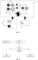
FIG. 1 is a schematic structural diagram of a refrigerated transportation system, -
FIG. 2 is a schematic structural diagram of a refrigeration unit, -
FIG. 3 is a flowchart of a method for controlling the refrigerated transportation system, -
FIG. 4 is a schematic structural diagram of the refrigerated transportation system, and -
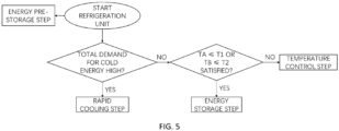
FIG. 5 is a flowchart of a method for controlling the refrigerated transportation system. - List of Reference Numerals: Refrigerated
transportation system 1,box 10,first area 10A,second area 10B,front wall 11,partition plate 12, first area current temperature TA, first area set temperature T1, second area current temperature TB, second area set temperature T2,refrigeration unit 20,first evaporator 21,first evaporation coil 211,first fan 212,second evaporator 22,second evaporation coil 221,second fan 222,phase change material 223,condenser 23,compressor 24,expansion valves element 30, on-board power source 40,fuel cell 41,storage battery 42. - It should be noted that working principles, characteristics, advantages and the like of a method for controlling a refrigerated transportation system, a refrigerated transportation system, and a computer-readable storage medium according to the present disclosure will be described below in an illustrative manner. However, it should be understood that all descriptions are given for illustrative purposes only and therefore should not be construed as any limitation to the present disclosure.
- In addition, for any single technical feature described or implied in the embodiments mentioned herein, or any single technical feature shown or implied in the accompanying drawings, the present disclosure still allows any combination or deletion between these technical features (or equivalents thereof) without any technical obstacles, thereby obtaining more other embodiments of the present disclosure that may not be directly mentioned herein. The scope of protection is defined by the appended claims.
- A method for controlling a refrigerated
transportation system 1, the refrigeratedtransportation system 1, a computer-readable storage medium, and the like are shown with reference to generally the accompanying drawings, according to an exemplary embodiment. The method includes a rapid cooling step of causing afirst evaporator 21 and asecond evaporator 22 to simultaneously exchange heat with air in abox 10, so that after the refrigeratedtransportation system 1 operates for a short period of time, the refrigeratedtransportation system 1 can provide a low-temperature environment that meets the needs of goods. - The refrigerated
transportation system 1 according to the embodiment of the present disclosure includes abox 10 and arefrigeration unit 20 with reference toFIGS. 1 and2 . Therefrigeration unit 20 includes afirst evaporator 21 and asecond evaporator 22 connected in parallel, and thesecond evaporator 22 has aphase change material 223. With reference toFIG. 3 , the method for controlling the refrigeratedtransportation system 1 according to the embodiment of the present disclosure includes the rapid cooling step of causing thefirst evaporator 21 and thesecond evaporator 22 to simultaneously exchange heat with the air in thebox 10 to release cold energy stored in thephase change material 223. By causing thefirst evaporator 21 and thesecond evaporator 22 to simultaneously exchange heat with the air in thebox 10, after the refrigeratedtransportation system 1 operates for a short period of time, the refrigeratedtransportation system 1 can provide a low-temperature environment that meets the needs of goods. - Specifically, in the illustrated embodiment, the refrigerated
transportation system 1 is a refrigerated vehicle. Therefrigeration unit 20 includes acompressor 24, acondenser 23, and thefirst evaporator 21 and thesecond evaporator 22 connected in parallel. Anexpansion valve 25 is disposed between thecondenser 23 and thefirst evaporator 21, and anexpansion valve 26 is disposed between thecondenser 23 and thesecond evaporator 22. Both thefirst evaporator 21 and thesecond evaporator 22 are disposed close to afront wall 11 of thebox 10 to supply cold energy into thebox 10. Thefirst evaporator 21 includes afirst evaporation coil 211 and afirst fan 212. By starting thefirst fan 212, thefirst evaporation coil 211 exchanges heat with the air in thebox 10. Thesecond evaporator 22 includes asecond evaporation coil 221, thephase change material 223 coupled to thesecond evaporation coil 221, and asecond fan 222. By starting thesecond fan 222, thephase change material 223 storing the cold energy exchanges heat with the air in thebox 10. - Although the refrigerated
transportation system 1 is shown as a refrigerated vehicle in the illustrated embodiment, the present disclosure is not limited thereto, and any system that can be used to transport goods that need to be stored at a low temperature is within the scope of the present disclosure. In an alternative embodiment, the refrigeratedtransportation system 1 may be a refrigerated ship, a refrigerated container, or the like. - Although a structure and a mounting position of the
refrigeration unit 20 are shown in the illustrated embodiment, the present disclosure is not limited thereto, and anyrefrigeration unit 20 capable of causing thefirst evaporator 21 and thesecond evaporator 22 connected in parallel to simultaneously exchange heat with the air in thebox 10 is within the scope of the present disclosure. In an alternative embodiment, therefrigeration unit 20 may be mounted to a top wall of thebox 10. In an alternative embodiment, only one fan may be provided in therefrigeration unit 20, and therefrigeration unit 20 may control the heat exchange between thefirst evaporator 21 and/or thesecond evaporator 22 and the air in thebox 10 through two openable air outlets. - In some embodiments, the
refrigeration unit 20 may perform a first refrigerant cycle and a second refrigerant cycle. In the first refrigerant cycle, a refrigerant discharged from thecompressor 24 returns to thecompressor 24 after passing through thecondenser 23, theexpansion valve 25 and thefirst evaporator 21. In the second refrigerant cycle, a refrigerant discharged from thecompressor 24 returns to thecompressor 24 after passing through thecondenser 23, theexpansion valve 26 and thesecond evaporator 22. In the rapid cooling step, therefrigeration unit 20 performs the first refrigerant cycle, that is, the refrigerant flows to thefirst evaporation coil 211 of thefirst evaporator 21, and at the same time, thefirst fan 212 operates at a high rotation speed, thereby increasing the cold energy supplied by thefirst evaporator 21 to thebox 10. In the rapid cooling step, therefrigeration unit 20 does not perform the second refrigerant cycle, that is, the refrigerant does not flow through theexpansion valve 26 and thesecond evaporator 22, but thesecond fan 222 operates at a high rotation speed, thereby promoting thephase change material 223 storing the cold energy to exchange heat with the air in thebox 10, that is, the cold energy is supplied into thebox 10 through thephase change material 223 disposed in thesecond evaporator 22. - Although the embodiment described above takes the example that the
refrigeration unit 20 performs the first refrigerant cycle in the rapid cooling step to illustrate a refrigerant operation mode in the rapid cooling step, the present disclosure is not limited thereto, and any refrigerant operation mode capable of improving the total cold energy supplied by thefirst evaporator 21 and thesecond evaporator 22 into thebox 10 is within the scope of the present disclosure. - For example, in the rapid cooling step, the
refrigeration unit 20 may perform the first refrigerant cycle and the second refrigerant cycle at the same time, and thefirst evaporation coil 211 of thefirst evaporator 21 and thesecond evaporation coil 221 of thesecond evaporator 22 may cool the air in thebox 10 and release the cold energy stored in thephase change material 223, so as to achieve the effect of rapid cooling more quickly. - In some embodiments, with reference to
FIG. 3 , the method includes a cold energy demand determination step of acquiring cold energy demand information of thebox 10, generating a rapid cooling instruction when the cold energy demand information meets a preset rapid cooling condition, and generating an energy storage instruction when the cold energy demand information meets a preset energy storage condition, a rapid cooling step of causing thefirst evaporator 21 and thesecond evaporator 22 to simultaneously exchange heat with air in thebox 10 to release the cold energy stored in thephase change material 223, in response to the rapid cooling instruction, and an energy storage step of causing thesecond evaporation coil 221 to exchange heat with thephase change material 223 so that thephase change material 223 stores cold energy, in response to the energy storage instruction. - Specifically, in the cold energy demand determination step, the cold energy demand information of the
box 10 is acquired. The cold energy demand information here refers to information that can reflect the demand for cold energy in thebox 10, and generally may include information on a current temperature and a set temperature information of thebox 10, information on an external environment temperature, and the like. In a case in which the set temperature is constant, the higher the current temperature in thebox 10, the larger the demand for cold energy in thebox 10, and the higher the external environment temperature, the larger the demand for cold energy in thebox 10. When the demand for cold energy in thebox 10 is large, the cold energy demand information meets the preset rapid cooling condition, and when the demand for cold energy in thebox 10 is small, the cold energy demand information meets the preset energy storage condition. - When the cold energy demand information meets the preset energy storage condition, an energy storage instruction is generated and the energy storage step is performed. In the energy storage step, the
refrigeration unit 20 may perform the first refrigerant cycle and the second refrigerant cycle, that is, that is, part of a refrigerant flows to thefirst evaporation coil 211 of thefirst evaporator 21 for adjusting or maintaining the temperature inside thebox 10, and part of the refrigerant flows to thesecond evaporation coil 221 of thesecond evaporator 22 for exchanging heat with thephase change material 223 to implement cold energy storage of thephase change material 223. In the energy storage step, thefirst evaporator 21 is used to adjust or maintain the temperature in thebox 10, specifically, thefirst evaporator 21 may change the amount of cold air supplied by thefirst evaporator 21 to thebox 10 by adjusting a rotation speed of thefirst fan 212. - In some embodiments, the cold energy demand information includes a difference between the current temperature and the set temperature in the
box 10, and according to a comparison result of the difference and a threshold, whether the preset rapid cooling condition is met and whether the preset energy storage condition is met are determined. For example, when the set temperature is -20°C, if the current temperature in thebox 10 is 20°C, the difference between the current temperature and the set temperature in thebox 10 is 40, which is large and greater than a threshold (assuming that the threshold is 10), the preset rapid cooling condition is met, and the rapid cooling instruction is generated. If the current temperature in thebox 10 is -10°C, the difference between the current temperature and the set temperature in thebox 10 is 10, which is small and less than or equal to the threshold (assuming that the threshold is 10), the preset energy storage condition is met, and the energy storage instruction is generated. - In the energy storage step, the
second evaporation coil 221 exchanges heat with thephase change material 223, so that thephase change material 223 stores the cold energy. Thefirst evaporation coil 211 exchanges heat with the air in thebox 10, so that the temperature in thebox 10 is further reduced from -10°C to -20°C and the temperature in thebox 10 reaches the set temperature. After the temperature in thebox 10 reaches the set temperature, thefirst fan 212 of thefirst evaporator 21 may be shut down to prevent the temperature in thebox 10 from being too low to adversely affect the goods therein. - In some embodiments, the
refrigerated transportation system 1 includes an on-board power source 40, and a plug-inelement 30 that can be coupled to an external power source. When therefrigerated transportation system 1 is in transit, the on-board power source 40 provides power to therefrigerated transportation system 1 including therefrigeration unit 20. When therefrigerated transportation system 1 is not in transit, the plug-inelement 30 is coupled to an external power source to provide power to therefrigeration unit 20. For example, the energy pre-storage step may be performed to allow thesecond evaporation coil 221 to exchange heat with thephase change material 223, so that thephase change material 223 stores the cold energy. Specifically, a plug-in element may be coupled to a power grid at night, valley electricity at night can be used to provide power therefrigeration unit 20, so that thephase change material 223 stores the cold energy. Thephase change material 223 storing the cold energy can be used to exchange heat with the air in thebox 10 in the rapid cooling step, thereby facilitating reduction of operating costs of therefrigerated transportation system 1. - In some embodiments, in the rapid cooling step and the energy storage step, the on-
board power source 40 provides power to therefrigeration unit 20. The on-board power source 40 may include afuel cell 41 and astorage battery 42 used in conjunction with thefuel cell 41. In the energy storage step, operating power of thefuel cell 41 is increased in a direction close to rated power of thefuel cell 41. When the demand for cold energy in thebox 10 is small, energy consumption of thefuel cell 41 is low, and thefuel cell 41 does not work within the rated power range, resulting in low efficiency of thefuel cell 41. Therefore, by performing the energy storage step, thefuel cell 41 provides power for therefrigeration unit 20, so that thephase change material 223 stores the cold energy, thereby increasing the energy consumption of thefuel cell 41, and causing thefuel cell 41 to work within the rated power range, thereby improving the efficiency. When the demand for cold energy in thebox 10 is large, effective heat exchange between thephase change material 223 storing the cold energy and the air in thebox 10 alleviates the problem of battery overheating caused by the increased energy consumption of thefuel cell 41, which is beneficial to the compact design of thefuel cell 41. - In some embodiments, the on-
board power source 40 is a diesel engine. In a specific embodiment, part of the power of the diesel engine is used to drive a generator to generate electricity, and the electricity generated by the diesel engine is used to drive electrical equipment such as fans and controllers. The other part of the power of the diesel engine is driven by a belt-driven compressor. The compressor mentioned here is an open compressor, which is not driven by electricity, but by pulleys and belts. - The
refrigerated transportation system 1 according to the embodiment of the present disclosure, as shown inFIGS. 2 and4 , includes thebox 10 and therefrigeration unit 20. Thebox 10 includes afirst area 10A and asecond area 10B isolated from each other, and therefrigeration unit 20 includes thefirst evaporator 21 and thesecond evaporator 22 connected in parallel. Thesecond evaporator 22 includes thesecond evaporation coil 221, and thesecond evaporation coil 221 is coupled to thephase change material 223. Thefirst evaporator 21 is disposed corresponding to thefirst area 10A, and thesecond evaporator 22 is disposed corresponding to thesecond area 10B. The method for controlling therefrigerated transportation system 1 according to the embodiment of the present disclosure includes the cold energy demand determination step of acquiring the cold energy demand information of thebox 10, generating a rapid cooling instruction when the cold energy demand information meets the preset rapid cooling condition, and generating an energy storage instruction when the cold energy demand information meets the preset energy storage condition, the rapid cooling step of causing thefirst evaporator 21 and thesecond evaporator 22 to simultaneously exchange heat with the air in thebox 10 to release the cold energy stored in thephase change material 223, in response to the rapid cooling instruction, and the energy storage step of causing thesecond evaporation coil 221 to exchange heat with thephase change material 223 so that thephase change material 223 stores cold energy, in response to the energy storage instruction. - Specifically, the
box 10 is divided into thefirst area 10A and thesecond area 10B by apartition plate 12, and set temperatures of thefirst area 10A and thesecond area 10B can be controlled separately. Thefirst area 10A and thesecond area 10B may be disposed inside thebox 10 in a front-back manner, or disposed inside thebox 10 in an up-down manner. Therefrigeration unit 20 includes thecompressor 24, thecondenser 23, thefirst evaporator 21 and thesecond evaporator 22 connected in parallel. Theexpansion valve 25 is disposed between thecondenser 23 and thefirst evaporator 21, and theexpansion valve 26 is disposed between thecondenser 23 and thesecond evaporator 22. Thefirst evaporator 21 is disposed close to thefront wall 11 of thebox 10 to supply cold energy to thefirst area 10A in thebox 10, and thesecond evaporator 22 is disposed close to thepartition plate 12 of thebox 10 to supply cold energy to thesecond area 10B in thebox 10. Thefirst evaporator 21 includes thefirst evaporation coil 211 and thefirst fan 212. By starting thefirst fan 212, thefirst evaporation coil 211 exchanges heat with the air in thefirst area 10A. Thesecond evaporator 22 includes thesecond evaporation coil 221, thephase change material 223 coupled to thesecond evaporation coil 221, and thesecond fan 222. By starting thesecond fan 222, thephase change material 223 storing the cold energy exchanges heat with the air in thesecond area 10B. - In some embodiments, with reference to
FIG. 5 , the cold energy demand information includes a first difference between a first area current temperature TA and a first area set temperature T1, and a second difference between a second area current temperature TB and a second area set temperature T2. The first difference reflects the demand for cold energy in thefirst area 10A, and the second difference reflects the demand for cold energy in thesecond area 10B. By combining the first difference and the second difference, the total demand for cold energy in thebox 10 can be known, and the total demand for cold energy in thebox 10 can be divided into two levels, namely, high total demand for cold energy and low total demand for cold energy. - When the total demand for cold energy is high, the preset rapid cooling condition is met, the rapid cooling instruction is generated, and the rapid cooling step is performed, that is, the
first evaporator 21 exchanges heat with the air in thebox 10, and at the same time, thesecond evaporator 22 exchanges heat with the air in thebox 10. - When the total demand for cold energy is low, and both the first difference and the second difference are greater than 0, that is, when the first area current temperature TA is greater than the first area set temperature T1 and the second area current temperature TB is greater than the second area set temperature T2, a preset temperature control condition is met, a temperature control instruction is generated, and a temperature control step is performed, that is, the
first evaporator 21 exchanges heat with the air in thebox 10, and at the same time, thesecond evaporator 22 exchanges heat with the air in thebox 10. - When the total demand for cold energy is low, and at least one of the first difference and the second difference is less than or equal to 0, that is, when the first area current temperature TA reaches the first area set temperature T1 or the second area current temperature TB reaches the second area set temperature T2, the preset energy storage condition is met, the energy storage instruction is generated, and the energy storage step is performed.
- In the energy storage step, when the first area current temperature TA reaches the first area set temperature T1 and the second area current temperature TB does not reach the second area set temperature T2 (TA ≤ T1 and TB > T2), the
first evaporator 21 is shut down, thesecond evaporator 22 stores cold energy and exchanges heat with the air in thebox 10, that is, thefirst fan 212 is shut down, thesecond evaporation coil 221 exchanges heat with thephase change material 223 so that thephase change material 223 stores cold energy, and at the same time, thephase change material 223 exchanges heat with the air in thebox 10 to release the cold energy stored in thephase change material 223. When the first area current temperature TA does not reach the first area set temperature T1 and the second area current temperature TB reaches the second area set temperature T2 (TA > T1 and TB ≤ T2), thefirst evaporator 21 exchanges heat with the air in thebox 10, thesecond evaporator 22 stores cold energy, that is, thefirst fan 212 operates, thesecond fan 222 is shut down, and thesecond evaporation coil 221 exchanges heat with thephase change material 223 so that thephase change material 223 stores cold energy. When the first area current temperature TA reaches the first area set temperature T1 and the second area current temperature TB reaches the second area set temperature T2 (TA ≤ T1 and TB ≤ T2), thefirst evaporator 21 is shut down, thesecond evaporator 22 stores cold energy, that is, thefirst fan 212 is shut down, thesecond fan 222 is shut down, and thesecond evaporation coil 221 exchanges heat with thephase change material 223, so that thephase change material 223 stores cold energy. - The
refrigerated transportation system 1 according to an embodiment of the present disclosure includes: abox 10; arefrigeration unit 20 including afirst evaporator 21 and asecond evaporator 22 connected in parallel, thesecond evaporator 22 including asecond evaporation coil 221, thesecond evaporation coil 221 being coupled with aphase change material 223; a processor; and a memory storing processor-readable instructions, the processor executing the following steps by running the processor-readable instructions: a cold energy demand determination step of acquiring cold energy demand information of thebox 10, generating a rapid cooling instruction when the cold energy demand information meets a preset rapid cooling condition, and generating an energy storage instruction when the cold energy demand information meets a preset energy storage condition, a rapid cooling step of causing thefirst evaporator 21 and thesecond evaporator 22 to simultaneously exchange heat with air in thebox 10 to release cold energy stored in thephase change material 223, in response to the rapid cooling instruction, and an energy storage step of causing thesecond evaporation coil 221 to exchange heat with thephase change material 223 so that thephase change material 223 stores cold energy, in response to the energy storage instruction. - The
refrigerated transportation system 1 according to another embodiment of the present disclosure includes: abox 10; arefrigeration unit 20 including afirst evaporator 21 and asecond evaporator 22 connected in parallel, thesecond evaporator 22 including asecond evaporation coil 221, thesecond evaporation coil 221 being coupled with aphase change material 223; a cold energy demand determination unit configured to acquire cold energy demand information of thebox 10, generate a rapid cooling instruction when the cold energy demand information meets a preset rapid cooling condition, and generate an energy storage instruction when the cold energy demand information meets a preset energy storage condition; a rapid cooling unit configured to cause thefirst evaporator 21 and thesecond evaporator 22 to simultaneously exchange heat with air in thebox 10 to release cold energy stored in thephase change material 223, in response to the rapid cooling instruction; and an energy storage unit configured to cause thesecond evaporation coil 221 to exchange heat with thephase change material 223 so that thephase change material 223 stores cold energy, in response to the energy storage instruction. - The computer-readable storage medium according to an embodiment of the present disclosure stores processor-readable instructions, and when the processor-readable instructions are executed by a processor, the method for controlling the refrigerated transportation system described in the above embodiments is implemented.
- The above embodiments are merely preferred embodiments of the present disclosure and are not intended to limit the present disclosure. The skilled person will appreciate that modifications may be made within the scope of the claims. The scope of protection is defined by the appended claims.
Claims (13)
- A method for controlling a refrigerated transportation system (1), the refrigerated transportation system including a box (10) and a refrigeration unit (20) disposed corresponding to the box, the refrigeration unit including a first evaporator (21) and a second evaporator (22) connected in parallel, the second evaporator having a phase change material (223), the method comprising:
a rapid cooling step of the first evaporator and the second evaporator simultaneously exchanging heat with air in the box to release cold energy stored in the phase change material. - The method for controlling a refrigerated transportation system according to claim 1, wherein the second evaporator includes a second evaporation coil (221), the phase change material is coupled to the second evaporation coil, and
the method further comprises:
an energy storage step of the second evaporation coil exchanging heat with the phase change material so that the phase change material stores cold energy. - The method for controlling a refrigerated transportation system according to claim 2, wherein the refrigerated transportation system further includes a plug-in element (3) capable of being coupled to an external power source, and the method further comprises:
an energy pre-storage step of the second evaporation coil exchanging heat with the phase change material so that the phase change material stores the cold energy when the plug-in element is coupled to the external power source. - The method for controlling a refrigerated transportation system according to claim 2 or 3, wherein the refrigerated transportation system further includes an on-board power source (40), and
in the rapid cooling step and the energy storage step, power is provided to the refrigeration unit through the on-board power source. - The method for controlling a refrigerated transportation system according to claim 4, wherein the on-board power source includes a fuel cell (41), and
in the energy storage step, operating power of the fuel cell is increased in a direction close to rated power of the fuel cell. - The method for controlling a refrigerated transportation system according to any one of claims 2 to 5, further comprising:a cold energy demand determination step of acquiring cold energy demand information of the box, generating a rapid cooling instruction when the cold energy demand information meets a preset rapid cooling condition, and generating an energy storage instruction when the cold energy demand information meets a preset energy storage condition, whereinthe rapid cooling step further includes a step of responding to the rapid cooling instruction, andthe energy storage step further includes a step of responding to the energy storage instruction.
- The method for controlling a refrigerated transportation system according to claim 6, wherein in the cold energy demand determination step, the cold energy demand information includes a difference between a current temperature and a set temperature in the box, and according to a comparison result of the difference and a threshold, whether the preset rapid cooling condition is met and whether the preset energy storage condition is met are determined.
- The method for controlling a refrigerated transportation system according to any preceding claim, wherein the box includes a first area (10A) and a second area (10B), the first evaporator is disposed corresponding to the first area, and the second evaporator is disposed corresponding to the second area.
- The method for controlling a refrigerated transportation system according to claim 8, wherein in the cold energy demand determination step, the cold energy demand information includes a first difference between a first area current temperature (TA) and a first area set temperature (T1) of the first area, and a second difference between a second area current temperature (TB) and a second area set temperature (T2) of the second area, and according to a comparison result of the first difference and the threshold and a comparison result of the second difference and the threshold, whether the preset energy storage condition is met is determined.
- The method for controlling a refrigerated transportation system according to claim 9, wherein the preset energy storage condition is that the first difference reaches the threshold or/and the second difference reaches the threshold.
- A refrigerated transportation system (1) comprising:a box (10);a refrigeration unit (20) disposed corresponding to the box and including a first evaporator (21) and a second evaporator (22) connected in parallel, the second evaporator including a second evaporation coil (221) and a phase change material (223) coupled to the second evaporation coil;a cold energy demand determination unit configured to acquire cold energy demand information of the box, generate a rapid cooling instruction when the cold energy demand information meets a preset rapid cooling condition, and generate an energy storage instruction when the cold energy demand information meets a preset energy storage condition;a rapid cooling unit configured to cause the first evaporator and the second evaporator to simultaneously exchange heat with air in the box to release cold energy stored in the phase change material, in response to the rapid cooling instruction; andan energy storage unit configured to cause the second evaporation coil to exchange heat with the phase change material so that the phase change material stores the cold energy, in response to the energy storage instruction.
- The refrigerated transportation system according to claim 11, wherein the refrigerated transportation system is a refrigerated vehicle, a refrigerated ship or a refrigerated container.
- A computer-readable storage medium storing processor-readable instructions,
wherein when the processor-readable instructions are executed by a processor, the method for controlling a refrigerated transportation system (1) according to any one of claims 1 to 10 is implemented.
Applications Claiming Priority (1)
| Application Number | Priority Date | Filing Date | Title |
|---|---|---|---|
| CN202311422123.XA CN119911065A (en) | 2023-10-30 | 2023-10-30 | Control method of refrigerated transportation system, refrigerated transportation system, and storage medium |
Publications (1)
| Publication Number | Publication Date |
|---|---|
| EP4549849A1 true EP4549849A1 (en) | 2025-05-07 |
Family
ID=93335511
Family Applications (1)
| Application Number | Title | Priority Date | Filing Date |
|---|---|---|---|
| EP24209967.9A Pending EP4549849A1 (en) | 2023-10-30 | 2024-10-30 | Method for controlling a refrigerated transportation system and refrigerated transportation system |
Country Status (3)
| Country | Link |
|---|---|
| US (1) | US20250135837A1 (en) |
| EP (1) | EP4549849A1 (en) |
| CN (1) | CN119911065A (en) |
Citations (3)
| Publication number | Priority date | Publication date | Assignee | Title |
|---|---|---|---|---|
| DE20115273U1 (en) * | 2001-01-05 | 2002-05-08 | Behr GmbH & Co., 70469 Stuttgart | Air conditioning for a motor vehicle |
| EP3288796B1 (en) * | 2015-05-01 | 2021-06-30 | Thermo King Corporation | Integrated thermal energy module within an air-cooled evaporator design |
| CN116215169A (en) * | 2023-02-02 | 2023-06-06 | 上海热翼智控系统有限公司 | On-board refrigeration system with direct evaporator and cold storage module |
Family Cites Families (1)
| Publication number | Priority date | Publication date | Assignee | Title |
|---|---|---|---|---|
| US20240367480A1 (en) * | 2023-05-05 | 2024-11-07 | Cummins Inc. | Cab heater systems for battery electric vehicles |
-
2023
- 2023-10-30 CN CN202311422123.XA patent/CN119911065A/en active Pending
-
2024
- 2024-10-20 US US18/920,921 patent/US20250135837A1/en active Pending
- 2024-10-30 EP EP24209967.9A patent/EP4549849A1/en active Pending
Patent Citations (3)
| Publication number | Priority date | Publication date | Assignee | Title |
|---|---|---|---|---|
| DE20115273U1 (en) * | 2001-01-05 | 2002-05-08 | Behr GmbH & Co., 70469 Stuttgart | Air conditioning for a motor vehicle |
| EP3288796B1 (en) * | 2015-05-01 | 2021-06-30 | Thermo King Corporation | Integrated thermal energy module within an air-cooled evaporator design |
| CN116215169A (en) * | 2023-02-02 | 2023-06-06 | 上海热翼智控系统有限公司 | On-board refrigeration system with direct evaporator and cold storage module |
Also Published As
| Publication number | Publication date |
|---|---|
| US20250135837A1 (en) | 2025-05-01 |
| CN119911065A (en) | 2025-05-02 |
Similar Documents
| Publication | Publication Date | Title |
|---|---|---|
| US11660934B2 (en) | Startup control systems and methods to reduce flooded startup conditions | |
| US11014427B2 (en) | Systems and methods for capacity modulation through eutectic plates | |
| US10654341B2 (en) | System and method of controlling passage of refrigerant through eutectic plates and an evaporator of a refrigeration system for a container of a vehicle | |
| CN109564047B (en) | Refrigeration system, vehicle and method for operating refrigeration system | |
| US10828963B2 (en) | System and method of mode-based compressor speed control for refrigerated vehicle compartment | |
| CN103502751B (en) | Transport refrigeration system and operational approach | |
| EP3479031A1 (en) | System and method of controlling compressor, evaporator fan, and condenser fan speeds during a battery mode of a refrigeration system for a container of a vehicle | |
| US20090133419A1 (en) | Trailer Refrigeration System | |
| US12257876B2 (en) | Thermal management system, thermal management method and electrical device | |
| US20250042218A1 (en) | Thermal management system for electric forklift | |
| CN112009244A (en) | Transport refrigeration system, control method thereof and electric transport vehicle | |
| US20180094846A1 (en) | Zone isolation control system for transport refrigeration unit | |
| US20250135837A1 (en) | Method for controlling refrigerated transportation system, refrigerated transportation system, and storage medium | |
| JP2024073319A (en) | Vehicle Air Conditioning Systems | |
| WO2015001976A1 (en) | Heat source system | |
| CN120986141A (en) | A method for switching battery thermal management modes based on a hot gas bypass heat pump system | |
| EP4414191A1 (en) | Thermal management system for a vehicle | |
| CN214199302U (en) | Air conditioning unit and refrigeration equipment | |
| CN217929305U (en) | Cooling equipment and tank container | |
| CN116857169A (en) | Heat dissipation control method and device for compressor, compressor and storage medium | |
| CN114608185B (en) | Air conditioner electronic control module heat dissipation control method, device, air conditioner and storage medium | |
| KR20230171107A (en) | A System for Controlling a Vehicle Refrigerator Droved by a Hydrogen Fuel Cell | |
| CN117022339B (en) | Integrated Thermal Management Control Method and System for Transcritical CO2 Heat Pump Air Conditioning Systems | |
| KR102385464B1 (en) | Low noise diesel generator using heat exchanger | |
| CN112539581A (en) | Air conditioning unit, refrigeration equipment and control method of air conditioning unit |
Legal Events
| Date | Code | Title | Description |
|---|---|---|---|
| PUAI | Public reference made under article 153(3) epc to a published international application that has entered the european phase |
Free format text: ORIGINAL CODE: 0009012 |
|
| STAA | Information on the status of an ep patent application or granted ep patent |
Free format text: STATUS: THE APPLICATION HAS BEEN PUBLISHED |
|
| AK | Designated contracting states |
Kind code of ref document: A1 Designated state(s): AL AT BE BG CH CY CZ DE DK EE ES FI FR GB GR HR HU IE IS IT LI LT LU LV MC ME MK MT NL NO PL PT RO RS SE SI SK SM TR |
|
| STAA | Information on the status of an ep patent application or granted ep patent |
Free format text: STATUS: REQUEST FOR EXAMINATION WAS MADE |
|
| 17P | Request for examination filed |
Effective date: 20251027 |