EP4549835A1 - Water heater - Google Patents
Water heater Download PDFInfo
- Publication number
- EP4549835A1 EP4549835A1 EP23207130.8A EP23207130A EP4549835A1 EP 4549835 A1 EP4549835 A1 EP 4549835A1 EP 23207130 A EP23207130 A EP 23207130A EP 4549835 A1 EP4549835 A1 EP 4549835A1
- Authority
- EP
- European Patent Office
- Prior art keywords
- pipe
- water
- water heater
- heater
- support structure
- Prior art date
- Legal status (The legal status is an assumption and is not a legal conclusion. Google has not performed a legal analysis and makes no representation as to the accuracy of the status listed.)
- Pending
Links
Images



Classifications
-
- F—MECHANICAL ENGINEERING; LIGHTING; HEATING; WEAPONS; BLASTING
- F24—HEATING; RANGES; VENTILATING
- F24H—FLUID HEATERS, e.g. WATER OR AIR HEATERS, HAVING HEAT-GENERATING MEANS, e.g. HEAT PUMPS, IN GENERAL
- F24H9/00—Details
- F24H9/20—Arrangement or mounting of control or safety devices
- F24H9/2007—Arrangement or mounting of control or safety devices for water heaters
- F24H9/2014—Arrangement or mounting of control or safety devices for water heaters using electrical energy supply
- F24H9/2028—Continuous-flow heaters
-
- F—MECHANICAL ENGINEERING; LIGHTING; HEATING; WEAPONS; BLASTING
- F24—HEATING; RANGES; VENTILATING
- F24H—FLUID HEATERS, e.g. WATER OR AIR HEATERS, HAVING HEAT-GENERATING MEANS, e.g. HEAT PUMPS, IN GENERAL
- F24H1/00—Water heaters, e.g. boilers, continuous-flow heaters or water-storage heaters
- F24H1/0072—Special adaptations
- F24H1/009—Special adaptations for vehicle systems
-
- F—MECHANICAL ENGINEERING; LIGHTING; HEATING; WEAPONS; BLASTING
- F24—HEATING; RANGES; VENTILATING
- F24H—FLUID HEATERS, e.g. WATER OR AIR HEATERS, HAVING HEAT-GENERATING MEANS, e.g. HEAT PUMPS, IN GENERAL
- F24H1/00—Water heaters, e.g. boilers, continuous-flow heaters or water-storage heaters
- F24H1/10—Continuous-flow heaters, i.e. heaters in which heat is generated only while the water is flowing, e.g. with direct contact of the water with the heating medium
- F24H1/101—Continuous-flow heaters, i.e. heaters in which heat is generated only while the water is flowing, e.g. with direct contact of the water with the heating medium using electric energy supply
- F24H1/102—Continuous-flow heaters, i.e. heaters in which heat is generated only while the water is flowing, e.g. with direct contact of the water with the heating medium using electric energy supply with resistance
- F24H1/105—Continuous-flow heaters, i.e. heaters in which heat is generated only while the water is flowing, e.g. with direct contact of the water with the heating medium using electric energy supply with resistance formed by the tube through which the fluid flows
-
- F—MECHANICAL ENGINEERING; LIGHTING; HEATING; WEAPONS; BLASTING
- F24—HEATING; RANGES; VENTILATING
- F24H—FLUID HEATERS, e.g. WATER OR AIR HEATERS, HAVING HEAT-GENERATING MEANS, e.g. HEAT PUMPS, IN GENERAL
- F24H1/00—Water heaters, e.g. boilers, continuous-flow heaters or water-storage heaters
- F24H1/10—Continuous-flow heaters, i.e. heaters in which heat is generated only while the water is flowing, e.g. with direct contact of the water with the heating medium
- F24H1/12—Continuous-flow heaters, i.e. heaters in which heat is generated only while the water is flowing, e.g. with direct contact of the water with the heating medium in which the water is kept separate from the heating medium
- F24H1/14—Continuous-flow heaters, i.e. heaters in which heat is generated only while the water is flowing, e.g. with direct contact of the water with the heating medium in which the water is kept separate from the heating medium by tubes, e.g. bent in serpentine form
- F24H1/142—Continuous-flow heaters, i.e. heaters in which heat is generated only while the water is flowing, e.g. with direct contact of the water with the heating medium in which the water is kept separate from the heating medium by tubes, e.g. bent in serpentine form using electric energy supply
Definitions
- This disclosure relates to a water heater for use in an aircraft.
- the disclosure relates to a water heater comprising an electric heater configured to heat the water inside a pipe.
- Water heaters may be used on aircraft to provide hot water for passengers on board the aircraft.
- water heaters may be used in a bathroom of an aircraft to provide hot water for passengers to wash their hands. Therefore, it is often desirable to produce a relatively small quantity of moderately hot water on demand for a short period of time.
- a tank may be used to store hot water. Storing pre-heated hot water may lead to wasted weight and space on board the aircraft if some of the pre-heated hot water in the tank is not used. Furthermore, there may be a delay before hot water begins to flow, as the tank is generally not located directly at the hot water outlet.
- the present disclosure aims to address some of these problems by providing a water heater for use in an aircraft.
- a water heater for use in an aircraft comprising:
- the pipe may be any type.
- the pipe is configured to provide a conduit for water between a source and an outlet. That is, the pipe may be configured to provide a path for water to flow between a source and an outlet.
- the pipe may be in fluid communication with a source of water (e.g. at a first end of the pipe) and an outlet for the water (e.g. at a second end of the pipe).
- the source and the outlet may be any type.
- the source of water may be a water tank of the aircraft.
- the outlet may be a tap of the aircraft.
- the tap of the aircraft may be located (e.g. of a sink) in (e.g. a vanity unit of) a bathroom of the aircraft (e.g. to be used by passengers of the aircraft).
- the pipe may contain water during use (e.g. as water flows between a source and an outlet). It will be understood that the pipe may contain any volume of water. In some examples, the pipe may be substantially full of water during use. In some examples, the pipe may be partially filled with water during use. The diameter and/or length of the pipe may be chosen such that the pipe is configured to provide a conduit between the source and the outlet for the desired volume of water.
- the electric heater may be any type.
- the electric heater may be a resistive heater (e.g. having a heating element configured to radiate heat).
- the heater may be powered by any suitable and desired source of electricity.
- the heater may be powered by a battery or generator (e.g. auxiliary power unit) of the aircraft.
- the electric heater extends along and/or around the outer surface of pipe.
- the electric heater may extend between a first point on the outer surface of the pipe and a second point on the outer surface of the pipe, wherein the first point and the second point are separated in at least the axial direction of the pipe (the direction in which the pipe extends longitudinally to convey the water).
- the electric heater may extend between a first point on the outer surface of the pipe and a second point on the outer surface of the pipe, wherein the first point and the second point are separated in at least the azimuthal direction of the pipe (e.g. around the perimeter of the pipe).
- the electric heater may extend between a first point on the outer surface of the pipe and a second point on the outer surface of the pipe, wherein the first point and the second point are separated in both the axial direction and the azimuthal direction of the pipe.
- the electric heater may extend along and/or around any proportion of the length of the pipe. In some examples, the electric heater may extend along and/or around only part of the pipe. In some examples, the electric heater may include a plurality of portions, each of which extends along and/or around a (e.g. different) portion of the pipe.
- the electric heater is configured to heat the water in the pipe.
- the electric heater may be configured to heat up when the water heater is in use.
- the heat produced by the electric heater may travel through the pipe to the water inside the pipe. Therefore, the heat produced by the electric heater may be used to heat the water in the pipe.
- the water is heated as it travels along the pipe between a source and an outlet.
- the water provided at the outlet may have a higher temperature than the water at the source.
- the planar support structure may be configured to support the pipe of the water heater.
- the planar support structure is formed of a stiff material, such that the planar support structure is configured to retain the pipe in its intended position.
- the planar support structure is formed of a lightweight material, such that the total weight of the water heater may be reduced.
- the planar support structure may be formed from a lightweight metal, a plastic and/or a fibre-reinforced polymer.
- the planar support structure may be any shape and size.
- the planar support structure is a plate, having a first planar surface facing on a first side and a second planar surface on a second, opposing side of the plate, separated across the thickness of the plate.
- the dimensions (e.g. length and width) of the planar surfaces may be much greater than the thickness of the plate.
- the planar surfaces are substantially square or rectangular.
- the pipe may be attached to a (first or second) planar surface of the planar support structure. At least part of the surface of the pipe may be in contact with a surface of the planar support structure along a substantial length of the pipe. As such, a surface along the pipe may lie in the plane of the planar surface. This may help to ensure that the desired length of pipe can be located inside the vanity unit. By arranging the pipe such that a surface along the pipe lies in a plane, the dimensions of the volume occupied by the pipe may be reduced in at least one direction.
- the mount may be any type configured to attach the water heater to a surface in a vanity unit of an aircraft.
- the mount may be formed as a unitary piece with the planar support structure.
- the vanity unit of the aircraft may be a storage unit and/or a support unit located proximal to a sink of the aircraft.
- the vanity unit is attached to and/or formed as a unitary piece with a washbasin of an aircraft.
- the vanity unit may extend below, around and/or on top of the sink (e.g. extending above the sink to support a mirror above the sink).
- the vanity unit is a cupboard located below the sink.
- the sink may rest on a surface of the vanity unit.
- the vanity unit comprises other components such as: a waste water pipe, a waste receptacle and/or a storage unit.
- the pipe is formed from a thermally conductive material such that the electric heater is configured to heat the water in the pipe.
- a thermally conductive material may be configured to conduct heat between the electric heater and the water in the pipe. This may help to ensure that the water in the pipe is heated effectively.
- the pipe is formed of a material with good thermal conductivity, such that heat is conducted efficiently between the electric heater and the water in the pipe.
- the pipe may be formed of a metal, such as copper.
- the electric heater is in good thermal communication with the (e.g. outer surface of the) pipe. This may help to conduct heat between the electric heater and the water (e.g. through the walls (outer surface) of the pipe).
- the electric heater extends helically around the outer surface of the pipe. This may help to increase the length of the electric heater for a given length of pipe (e.g. compared to using a linear electric heater). This may help to increase the amount of heat supplied to the water in the pipe, thereby helping to increase the temperature of the water provided at the outlet and/or the efficiency of the water heater.
- the electric heater extends (continuously or discontinuously) along a substantial length of the pipe (e.g. between the source and the outlet). This may help to ensure that the water is heated over a significant proportion of the pipe as it travels between the source and the outlet, thereby helping to ensure that the water is heated to the desired temperature.
- the electric heater extends (continuously or discontinuously) along at least 50% of the pipe, optionally along at least 60% of the pipe, optionally along at least 70% of the pipe, optionally along at least 80% of the pipe, optionally along at least 90% of the pipe.
- the electric heater may be formed of more than one part, each of which extends along part of the pipe. Each part of the electric heater may be connected in any suitable and desired way to any other part of the electric heater. The different parts of the electric heater may operate separately or together.
- the electric heater may extend along the substantially linear portions of the pipe. This may help to simplify manufacture of the water heater, as the electric heater may not be required to conform to any bends and/or curves in the pipe.
- the pipe substantially covers the surface of the planar support structure. This may help to increase the length of the pipe for a planar support structure of a given surface area. This may help to increase the volume of water that the pipe is configured to hold, thereby increasing the volume of heated water that may be supplied at the outlet.
- the pipe covers at least 60% of the surface of the planar support structure, optionally at least 70% of the surface of the planar support structure, at least 80% of the surface of the planar support structure, at least 90% of the surface of the planar support structure.
- the pipe comprises a plurality of substantially parallel portions.
- the plurality of substantially parallel portions may have substantially the same length as a dimension (e.g. a width or a length) of the planar support structure. This may help to ensure that the pipe substantially covers the surface of the planar support structure.
- the substantially parallel portions are linear. This may help to simplify manufacture of the water heater.
- each of the plurality of substantially parallel portions are connected to an adjacent substantially parallel portion at their respective ends, such that the pipe forms a continuous path between the water source and the water outlet.
- the pipe may follow a boustrophedonic path across a surface of the planar support structure. This may help to ensure that the pipe substantially covers the surface of the planar support structure.
- the pipe may follow any suitable and desired path across the surface of the planar support structure.
- the pipe may follow a spiral shaped path or a labyrinthine path.
- the pipe is attached to a surface of the planar support structure by an adhesive.
- the adhesive may be any suitable and desired type.
- the adhesive may be applied along any portion of the pipe. In some examples, the adhesive may extend along substantially the entire pipe.
- the mount for attaching the water heater to a surface of the aircraft comprises at least one aperture in the planar support structure.
- the aperture(s) may (e.g. each) be configured to receive a fixing member such as a screw, such that the water heater may be attached to a surface in a vanity unit of an aircraft.
- the water heater further comprises a thermostat.
- the thermostat may be any suitable and desired type.
- the thermostat may be configured to receive (e.g. as an input from a user) a target temperature of the water, measure the temperature of the water and adjust the operation of the water heater such that the water reaches its target temperature.
- the thermostat may be configured to measure the temperature of the water by any suitable and desired means.
- the thermostat is configured to measure the temperature of the water proximal to the output of the water heater. This may help to ensure that the measured temperature is substantially the same as the temperature of the water at the output (e.g. the temperature of the water during use).
- the thermostat is configured to receive one or more inputs (e.g. from a user).
- the thermostat may receive one or more inputs from one or more of the following: a button, a switch, a remote controller and/or a control dial which may be used (e.g. by a user) to adjust the operating parameters of the thermostat.
- a user may input the target temperature of the water.
- the target temperature is set during installation and/or maintenance of the water heater and cannot be adjusted by a user during normal use (e.g. by a passenger on board an aircraft).
- the thermostat may be configured to send one or more commands to the water heater.
- the water heater may be configured to adjust the power provided to the electric heater based on one or more commands from the thermostat.
- the water heater may be configured to adjust the power provided to the electric heater to achieve a number of operational conditions. For example, the power may be adjusted such that the temperature of the water at the outlet increases over time, decreases over time, or is maintained over time.
- the power may be adjusted such that the temperature of the water at the outlet is maintained at the target temperature set by (e.g. a user as an input to) the thermostat.
- the thermostat comprises a temperature sensor in fluid communication with the water in the pipe; and wherein the water heater is configured to adjust the power provided to the electric heater based on the measurements from the temperature sensor.
- the temperature sensor may be any suitable and desired type. It may be in fluid communication with the water in any manner. In some examples, at least part of the temperature sensor may be located inside the pipe. In some examples, the temperature sensor may be located proximal to the output of the water heater. This may help to ensure that the measured temperature is substantially the same as the temperature of the water at the output (e.g. the temperature of the water during use).
- the thermostat comprises a digital display configured to display the actual and/or target temperature of the water. This may help to ensure that the target temperature can be set to the desired temperature and/or that the operation of the water heater can be monitored and/or assessed.
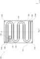
- Figure 1 is a schematic front view of a water heater 2 according to an example of the present disclosure.
- the water heater 2 includes a pipe 4 configured to provide a conduit for water between a source 6 and an outlet 8.
- the source 6 is a water tank of the aircraft (not shown) and the outlet 8 is a tap of the aircraft (not shown).
- the tap may be located in a bathroom of the aircraft and may be used by passengers of the aircraft (e.g. to wash their hands).
- the water heater 2 further includes an electric heater 10.
- the pipe 4 contains water.
- the electric heater 10 is configured to heat the water in the pipe 4.
- the electric heater 10 may be any type of heater that is configured to heat the water in the pipe 4. In this example, the electric heater 10 is a resistive heater.
- the water heater 2 further includes a planar support structure 12.
- the planar support structure 12 is substantially planar in the x-y plane.
- the planar support structure 12 is also substantially square in the x-y plane.
- the planar support structure 12 may have any suitable and desired shape.
- the pipe 4 is attached to a surface of the planar support structure 12 such that the pipe 4 follows a non-linear path across the surface of the planar support structure 12.
- the pipe 4 is attached to a surface of the planar support structure 12 in the x-y plane. Therefore, the pipe 4 follows a substantially planar path in the x-y plane.
- the non-linear path followed by the pipe 4 in this example comprises a number of parallel linear portions connected at their respective ends by curved portions. This non-linear path may help to ensure that the pipe 4 has a length of at least 1 metre, while still being compact enough to be positioned inside a vanity unit of the aircraft. In this example, the pipe 4 occupies a substantial portion of the surface of the planar support structure 12. This may also help to ensure that the water heater is sufficiently compact.
- the planar support structure 12 comprises brackets 14a-d configured to be attached to a surface in the vanity unit (not shown).
- the brackets 14a-d extend from each of the corners of the planar support structure 12.
- any number of brackets 14a-d may be used, and the brackets 14a-d may be located anywhere on the planar support structure 12.
- the water heater 2 further includes a thermostat 16.
- the thermostat 16 includes a digital display 18 configured to display the actual and/or target temperature of the water.
- the thermostat 16 includes a control dial 20.
- the control dial 20 may be used to adjust the operating parameters of the thermostat. For example, a user may use the control dial 20 to select the target temperature of the water. It will be understood that the control dial 20 is exemplary, and the thermostat 16 could additionally or alternatively receive input from one or more buttons, switches, or remote controllers.
- the thermostat 16 may include a temperature sensor (not shown) in fluid communication with the water in the pipe 4.
- the temperature sensor may extend from the back surface of the thermostat 16 through a sealed aperture in the pipe 4 such that the temperature sensor is in contact with the water in the pipe 4.
- the water heater 2 may be configured to adjust the power provided to the electric heater 10 based on the measurements from the temperature sensor and/or based on commands from the thermostat 16.
- the water heater 2 may be configured to adjust the power provided to the electric heater 10 to achieve a number of operation conditions. For example, the power may be adjusted such that the temperature of the water at the outlet 8 increases over time, decreases over time, or is maintained over time. The power may be adjusted such that the temperature of the water at the outlet 8 is maintained at the target temperature set by (e.g. a user via) the thermostat 16.
- Figure 2 is a schematic cross-sectional view of the water heater 2 of Figure 1 .
- the cross-section is along the line A indicated in Figure 1 .
- Figure 2 shows the pipe 4 attached to a surface of the planar support structure 12.
- the pipe 4 may be attached to the surface of the planar support structure 12 in any manner, for example by an adhesive and/or by one or more fixing members (e.g. screws, brackets or hooks).
- the electric heater 10 can be seen as a dashed line on Figure 2 . In this example, the electric heater 10 extends helically around the outer surface of the pipe 4.
- the pipe 4 extends along a first surface 12a of the planar support structure 12 such that the pipe 4 is arranged in a substantially planar manner in the x-y plane.
- the planar support structure 12 may be configured such that the second surface 12b is in contact with the surface of the vanity unit of an aircraft (not shown) when the planar support structure 12 is mounted to said surface.
- FIG 3 is a schematic front view of a water heater 102 according to an example of the present disclosure.
- the water heater 102 of this example comprises many of the same features as that of Figures 1 and 2 .
- the electric heater 110 extends axially along the outer surface of the pipe 104.
- the electric heater 110 extends along the longitudinal axis of the linear portions of the pipe 104. This may help to simplify manufacture of the water heater10 2 (e.g. if the electric heater 110 is rigid such that it does not easily bend around the curved portions of the pipe 104).
- planar support structure 112 is substantially planar and rectangular in the x-y plane. However, it will be understood that the planar support structure 112 may have any suitable and desired shape.
- the non-linear path followed by the pipe 104 in this example is similar to that of the pipe 104 in Figures 1 and 2 . However, it can be seen that the radius of the pipe 104 is smaller in this example.
- the radius and/or length of the pipe 104 may be selected such that the water heater 102 is configured to heat the desired volume of water. In some applications, it may be desirable to heat a smaller volume of water (e.g. to prevent unnecessary power use in heating water that will not be used).
- the planar support structure 112 comprises apertures 114a-d configured to receive a fixing member (e.g. a screw) such that the planar support surface 112 may be attached to a surface in the vanity unit (not shown).
- a fixing member e.g. a screw
- the apertures 114a-d are located proximal to each of the corners of the planar support structure 112.
- any number of apertures 114a-d may be used, and the apertures 114a-d may be located anywhere on the planar support structure 112.
- the water heater 102 further includes a thermostat 116 including a digital display 118 and a control dial 120 as discussed in relation to Figures 1 and 2 .
- the temperature sensor may located inside the pipe 104 and may be configured to communicate (e.g. wirelessly) with the thermostat 116.
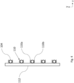
- Figure 4 is a schematic cross-sectional view of the water heater 102 of Figure 3 .
- the cross-section is along the line B indicated in Figure 3 .
- the cross-section is along the line B indicated in Figure 3 .
- Figure 1 shows the pipe 104 attached to a surface of the planar support structure 112.
- the pipe 104 may be attached to the surface of the planar support structure 112 in any manner, for example by an adhesive and/or by one or more fixing members (e.g. screws, brackets or hooks).
- the electric heater 110 does not extend around the entire outer perimeter of the pipe 104.
- the electric heater 110 is formed from two portions, 110a and 11 0b, along each of the parallel linear portions of the pipe 104.
- the two portions 110a and 110b are located on two diametrically opposing sides of the pipe 104 and are in contact with the outer surface of the pipe 104.
- each portion 110a and 110b of the electric heater 110 has a rectangular cross-section in the y-z plane, such that each portion 110a and 110b is in tangential contact with the pipe 104.
- This arrangement may still provide sufficient heating to the water in the pipe 104.
- This arrangement may help to simplify manufacture of the water heater 102, as the electric heater 110 is not required to conform precisely to the curvature of the pipe 104.
- the pipe 104 extends along a first surface 112a of the planar support structure 112 such that the pipe 104 is arranged in a substantially planar manner in the x-y plane.
- the planar support structure 112 may be configured such that the second surface 112b is in contact with the surface of the vanity unit of an aircraft (not shown) when the planar support structure 112 is mounted to said surface.
- Figure 5a is a schematic view of a vanity unit 22 including a water heater comprising a tank 24. This arrangement is an example of an existing water heater 2 that is common in the art.
- the vanity unit 22 is located underneath a sink in a bathroom of an aircraft.
- the tank 24 of the water heater is connected between an inlet pipe 26 and an outlet pipe 28.
- the inlet pipe 26 connects the input of the tank 24 to a source and the outlet pipe 28 connects the output of the tank 24 to an outlet.
- the source 6 is a water tank of the aircraft (not shown) and the outlet 8 is a tap of the aircraft (not shown).
- the vanity unit 22 comprises other components 30, shown schematically in the figures.
- the other components 30 may be any component of a vanity unit 22.
- the other components 30 include one or more of: a waste water pipe; a waste receptacle and/or a storage unit.
- the tank 24 is located in a space between the other components 30 of the vanity unit 22. This results in the outlet pipe 28 having a length L1. This will be discussed in more detail in relation to Figure 5b .
- Figure 5b is a schematic view of a vanity unit 122 including a water heater 2 according to an example of the present disclosure.
- the water heater 2 is connected between an inlet pipe 126 and an outlet pipe 128.
- the inlet pipe 126 connects the water heater 2 to a source and the outlet pipe 128 connects the output of the water heater 2 to an outlet.
- the inlet pipe 126 and/or the outlet pipe 128 are formed as a unitary piece with the pipe 4 of the water heater 2.
- the source 6 is a water tank of the aircraft (not shown) and the outlet 8 is a tap of the aircraft (not shown). Therefore, the inlet pipe 126 may be configured to supply cold (i.e. unheated) water to the water heater 2 and the outlet pipe 128 may be configured to supply hot (i.e. heated) water to a tap of the aircraft (not shown).
- the water heater 2 of the present disclosure heats water as it flows through the pipe 4, this removes any need for a tank 24. This may help to reduce the weight of the water stored on the aircraft.
- the water heater 2 is attached to a surface 32 in the vanity unit 122.
- a surface of the planar support structure 112 is configured to be in contact with the surface 32 of the vanity unit 122 to which to which the water heater 2 is attached.
- the vanity unit 122 of Figure 5b is similar to that of Figure 5a .
- the vanity unit 122 comprises other components 130.
- the other components 130 may include one or more of: a waste water pipe; a waste receptacle and/or a storage unit.
- the water heater 2 of the present disclosure has a smaller volume than the tank 24. Furthermore, the water heater 2 of the present disclosure has smaller dimensions along the z-direction. This may be advantageous because it allows the water heater 2 of the present disclosure to be located closer to the outlet. Therefore, the outlet pipe 128 may be shorter (having length L2) than the outlet pipe 28 of the system shown in Figure 5a (having length L1). As the outlet pipe 128 carries hot (i.e. heated water) to the outlet, heat may dissipate through the outlet pipe 128, such that the temperature of the water at the outlet is reduced. By reducing the length of the outlet pipe 128, the amount of heat dissipated through the outlet pipe 128 may be reduced, which may help to ensure that the water at the outlet is the desired temperature.
- the water heater 2 of the present disclosure may be more conveniently located against a surface 32 of the vanity unit 122. This may help to free up space in the vanity unit 122.
- the space previously occupied by the water tank 24 is shown as a dashed box in Figure 5b . This space may be advantageously used for other purposes. This may be particularly advantageous on an aircraft, where space is generally limited.
Landscapes
- Engineering & Computer Science (AREA)
- Physics & Mathematics (AREA)
- Thermal Sciences (AREA)
- Chemical & Material Sciences (AREA)
- Combustion & Propulsion (AREA)
- Mechanical Engineering (AREA)
- General Engineering & Computer Science (AREA)
- Fluid Mechanics (AREA)
- Heat-Pump Type And Storage Water Heaters (AREA)
Abstract
A water heater (2) for use in an aircraft, including a pipe (4) having a length of at least 1 metre and being configured to provide a conduit for water between a source (6) and an outlet (8). The water heater (2) includes an electric heater (10). The electric heater (10) extends around an outer surface of the pipe (4). The electric heater (10) is configured to heat the water in the pipe (4). The water heater (2) further includes a planar support structure (12). The pipe (4) is attached to a surface of the planar support structure (12) such that the pipe (4) follows a nonlinear path across the surface of the planar support structure (12). The planar support structure (12) comprises a structure (14a-d) for attaching the water heater (2) to a surface (32) in a vanity unit (22) of an aircraft.
Description
- This disclosure relates to a water heater for use in an aircraft. In particular, the disclosure relates to a water heater comprising an electric heater configured to heat the water inside a pipe.
- Water heaters may be used on aircraft to provide hot water for passengers on board the aircraft. In particular, water heaters may be used in a bathroom of an aircraft to provide hot water for passengers to wash their hands. Therefore, it is often desirable to produce a relatively small quantity of moderately hot water on demand for a short period of time.
- In some systems, a tank may be used to store hot water. Storing pre-heated hot water may lead to wasted weight and space on board the aircraft if some of the pre-heated hot water in the tank is not used. Furthermore, there may be a delay before hot water begins to flow, as the tank is generally not located directly at the hot water outlet. The present disclosure aims to address some of these problems by providing a water heater for use in an aircraft.
- According to the present disclosure, there is provided a water heater for use in an aircraft, comprising:
- a pipe having a length of at least 1 metre and being configured to provide a conduit for water between a source and an outlet; and
- an electric heater;
- wherein the electric heater extends along and/or around an outer surface of the pipe; and
- wherein the electric heater is configured to heat the water in the pipe;
- wherein the water heater further comprises a planar support structure;
- wherein the pipe is attached to a surface of the planar support structure such that the pipe follows a non-linear path across the surface of the planar support structure; and
- wherein the planar support structure comprises a mount for attaching the water heater to a surface in a vanity unit of an aircraft.
- The pipe may be any type. The pipe is configured to provide a conduit for water between a source and an outlet. That is, the pipe may be configured to provide a path for water to flow between a source and an outlet. The pipe may be in fluid communication with a source of water (e.g. at a first end of the pipe) and an outlet for the water (e.g. at a second end of the pipe).
- The source and the outlet may be any type. In some examples, the source of water may be a water tank of the aircraft. In some examples, the outlet may be a tap of the aircraft. In some examples, the tap of the aircraft may be located (e.g. of a sink) in (e.g. a vanity unit of) a bathroom of the aircraft (e.g. to be used by passengers of the aircraft).
- The pipe may contain water during use (e.g. as water flows between a source and an outlet). It will be understood that the pipe may contain any volume of water. In some examples, the pipe may be substantially full of water during use. In some examples, the pipe may be partially filled with water during use. The diameter and/or length of the pipe may be chosen such that the pipe is configured to provide a conduit between the source and the outlet for the desired volume of water.
- The electric heater may be any type. In some examples, the electric heater may be a resistive heater (e.g. having a heating element configured to radiate heat). The heater may be powered by any suitable and desired source of electricity. For example, the heater may be powered by a battery or generator (e.g. auxiliary power unit) of the aircraft.
- The electric heater extends along and/or around the outer surface of pipe. In examples where the electric heater extends along the outer surface of the pipe, the electric heater may extend between a first point on the outer surface of the pipe and a second point on the outer surface of the pipe, wherein the first point and the second point are separated in at least the axial direction of the pipe (the direction in which the pipe extends longitudinally to convey the water).
- In examples where the electric heater extends around the outer surface of the pipe, the electric heater may extend between a first point on the outer surface of the pipe and a second point on the outer surface of the pipe, wherein the first point and the second point are separated in at least the azimuthal direction of the pipe (e.g. around the perimeter of the pipe).
- In examples where the electric heater extends along and around the outer surface of the pipe, the electric heater may extend between a first point on the outer surface of the pipe and a second point on the outer surface of the pipe, wherein the first point and the second point are separated in both the axial direction and the azimuthal direction of the pipe.
- The electric heater may extend along and/or around any proportion of the length of the pipe. In some examples, the electric heater may extend along and/or around only part of the pipe. In some examples, the electric heater may include a plurality of portions, each of which extends along and/or around a (e.g. different) portion of the pipe.
- The electric heater is configured to heat the water in the pipe. The electric heater may be configured to heat up when the water heater is in use. The heat produced by the electric heater may travel through the pipe to the water inside the pipe. Therefore, the heat produced by the electric heater may be used to heat the water in the pipe. In some examples, the water is heated as it travels along the pipe between a source and an outlet. The water provided at the outlet may have a higher temperature than the water at the source.
- The planar support structure may be configured to support the pipe of the water heater. In some examples, the planar support structure is formed of a stiff material, such that the planar support structure is configured to retain the pipe in its intended position. Furthermore, in some examples, the planar support structure is formed of a lightweight material, such that the total weight of the water heater may be reduced. For example, the planar support structure may be formed from a lightweight metal, a plastic and/or a fibre-reinforced polymer.
- The planar support structure may be any shape and size. In some examples, the planar support structure is a plate, having a first planar surface facing on a first side and a second planar surface on a second, opposing side of the plate, separated across the thickness of the plate. The dimensions (e.g. length and width) of the planar surfaces may be much greater than the thickness of the plate. In some examples, the planar surfaces are substantially square or rectangular.
- The pipe may be attached to a (first or second) planar surface of the planar support structure. At least part of the surface of the pipe may be in contact with a surface of the planar support structure along a substantial length of the pipe. As such, a surface along the pipe may lie in the plane of the planar surface. This may help to ensure that the desired length of pipe can be located inside the vanity unit. By arranging the pipe such that a surface along the pipe lies in a plane, the dimensions of the volume occupied by the pipe may be reduced in at least one direction.
- The mount may be any type configured to attach the water heater to a surface in a vanity unit of an aircraft. The mount may be formed as a unitary piece with the planar support structure.
- The vanity unit of the aircraft may be a storage unit and/or a support unit located proximal to a sink of the aircraft. In some examples, the vanity unit is attached to and/or formed as a unitary piece with a washbasin of an aircraft. In some examples, the vanity unit may extend below, around and/or on top of the sink (e.g. extending above the sink to support a mirror above the sink). In some examples, the vanity unit is a cupboard located below the sink. In some examples, the sink may rest on a surface of the vanity unit. In some examples, the vanity unit comprises other components such as: a waste water pipe, a waste receptacle and/or a storage unit.
- In some examples, the pipe is formed from a thermally conductive material such that the electric heater is configured to heat the water in the pipe. A thermally conductive material may be configured to conduct heat between the electric heater and the water in the pipe. This may help to ensure that the water in the pipe is heated effectively. In some examples, the pipe is formed of a material with good thermal conductivity, such that heat is conducted efficiently between the electric heater and the water in the pipe. For example, the pipe may be formed of a metal, such as copper.
- In some examples, the electric heater is in good thermal communication with the (e.g. outer surface of the) pipe. This may help to conduct heat between the electric heater and the water (e.g. through the walls (outer surface) of the pipe).
- In some examples, the electric heater extends helically around the outer surface of the pipe. This may help to increase the length of the electric heater for a given length of pipe (e.g. compared to using a linear electric heater). This may help to increase the amount of heat supplied to the water in the pipe, thereby helping to increase the temperature of the water provided at the outlet and/or the efficiency of the water heater.
- In some examples, the electric heater extends (continuously or discontinuously) along a substantial length of the pipe (e.g. between the source and the outlet). This may help to ensure that the water is heated over a significant proportion of the pipe as it travels between the source and the outlet, thereby helping to ensure that the water is heated to the desired temperature.
- In some examples, the electric heater extends (continuously or discontinuously) along at least 50% of the pipe, optionally along at least 60% of the pipe, optionally along at least 70% of the pipe, optionally along at least 80% of the pipe, optionally along at least 90% of the pipe.
- In some examples, the electric heater may be formed of more than one part, each of which extends along part of the pipe. Each part of the electric heater may be connected in any suitable and desired way to any other part of the electric heater. The different parts of the electric heater may operate separately or together.
- In some examples, the electric heater may extend along the substantially linear portions of the pipe. This may help to simplify manufacture of the water heater, as the electric heater may not be required to conform to any bends and/or curves in the pipe.
- In some examples, the pipe substantially covers the surface of the planar support structure. This may help to increase the length of the pipe for a planar support structure of a given surface area. This may help to increase the volume of water that the pipe is configured to hold, thereby increasing the volume of heated water that may be supplied at the outlet. In some examples, the pipe covers at least 60% of the surface of the planar support structure, optionally at least 70% of the surface of the planar support structure, at least 80% of the surface of the planar support structure, at least 90% of the surface of the planar support structure.
- In some examples, the pipe comprises a plurality of substantially parallel portions. In some examples, the plurality of substantially parallel portions may have substantially the same length as a dimension (e.g. a width or a length) of the planar support structure. This may help to ensure that the pipe substantially covers the surface of the planar support structure. In some examples, the substantially parallel portions are linear. This may help to simplify manufacture of the water heater.
- In some examples, each of the plurality of substantially parallel portions are connected to an adjacent substantially parallel portion at their respective ends, such that the pipe forms a continuous path between the water source and the water outlet. The pipe may follow a boustrophedonic path across a surface of the planar support structure. This may help to ensure that the pipe substantially covers the surface of the planar support structure.
- The pipe may follow any suitable and desired path across the surface of the planar support structure. In some examples, the pipe may follow a spiral shaped path or a labyrinthine path.
- In some examples, the pipe is attached to a surface of the planar support structure by an adhesive. The adhesive may be any suitable and desired type. The adhesive may be applied along any portion of the pipe. In some examples, the adhesive may extend along substantially the entire pipe.
- In some examples, the mount for attaching the water heater to a surface of the aircraft comprises at least one bracket formed as a unitary piece with the planar support structure. The bracket(s) may be secured to the vanity unit using any suitable means, for example an adhesive and/or at least one fixing member such as a screw. The bracket(s) may be any shape. In some examples, the shape of the bracket(s) may be configured to at least partially wrap around a part of the vanity unit of the aircraft. Forming the bracket as a unitary piece with the planar support structure may help to simplify installation of the water heater by reducing the number of parts to be assembled.
- In some examples, the mount for attaching the water heater to a surface of the aircraft comprises at least one aperture in the planar support structure. The aperture(s) may (e.g. each) be configured to receive a fixing member such as a screw, such that the water heater may be attached to a surface in a vanity unit of an aircraft.
- In some examples, the water heater further comprises a thermostat. The thermostat may be any suitable and desired type. The thermostat may be configured to receive (e.g. as an input from a user) a target temperature of the water, measure the temperature of the water and adjust the operation of the water heater such that the water reaches its target temperature.
- The thermostat may be configured to measure the temperature of the water by any suitable and desired means. In some examples, the thermostat is configured to measure the temperature of the water proximal to the output of the water heater. This may help to ensure that the measured temperature is substantially the same as the temperature of the water at the output (e.g. the temperature of the water during use).
- In some examples, the thermostat is configured to receive one or more inputs (e.g. from a user). For example, the thermostat may receive one or more inputs from one or more of the following: a button, a switch, a remote controller and/or a control dial which may be used (e.g. by a user) to adjust the operating parameters of the thermostat. For example, a user may input the target temperature of the water. In some examples, the target temperature is set during installation and/or maintenance of the water heater and cannot be adjusted by a user during normal use (e.g. by a passenger on board an aircraft).
- The thermostat may be configured to send one or more commands to the water heater. The water heater may be configured to adjust the power provided to the electric heater based on one or more commands from the thermostat. The water heater may be configured to adjust the power provided to the electric heater to achieve a number of operational conditions. For example, the power may be adjusted such that the temperature of the water at the outlet increases over time, decreases over time, or is maintained over time. The power may be adjusted such that the temperature of the water at the outlet is maintained at the target temperature set by (e.g. a user as an input to) the thermostat.
- In some examples, the thermostat comprises a temperature sensor in fluid communication with the water in the pipe; and
wherein the water heater is configured to adjust the power provided to the electric heater based on the measurements from the temperature sensor. - The temperature sensor may be any suitable and desired type. It may be in fluid communication with the water in any manner. In some examples, at least part of the temperature sensor may be located inside the pipe. In some examples, the temperature sensor may be located proximal to the output of the water heater. This may help to ensure that the measured temperature is substantially the same as the temperature of the water at the output (e.g. the temperature of the water during use).
- The temperature sensor may provide measurements to the thermostat continuously or at (e.g. predetermined) intervals. In some examples, the temperature sensor may provide feedback to the thermostat only when the electric heater is switched on (e.g. when a current is flowing through the electric heater). This may help to avoid the operation of the electric heater being adjusted when the water heater is not in use. The temperature sensor may communicate with the thermostat in any manner, for example using a wired or a wireless connection.
- In some examples, the thermostat comprises a digital display configured to display the actual and/or target temperature of the water. This may help to ensure that the target temperature can be set to the desired temperature and/or that the operation of the water heater can be monitored and/or assessed.
- In some examples, the water heater is configured to increase the temperature of the water by at least 15 degrees Celsius, optionally at least 20 degrees Celsius, optionally at least 30 degrees Celsius, optionally at least 40 degrees Celsius.
- In some examples, it may be preferable to heat the water to a temperature significantly below boiling temperature (i.e. significantly below 100 degrees Celsius) and/or below scalding temperature (e.g. below approximately 60 degrees Celsius). In particular, this may be preferable if the water heater is being used to supply water to a tap to be used by a person (e.g. to wash their hands). This may help to prevent injuries such as scalds and burns. This may be particularly preferable if there is no separate cold water outlet. Therefore, in some examples, it may be preferable that the water heater increases the temperature of the water from room temperature (e.g. approximately 13-16 degrees Celsius) to a temperature suitable for use without further cooling of the water (e.g. approximately 32-54 degrees Celsius).
- Certain examples of the present disclosure will now be described with reference to the accompanying drawings in which:
-
Figure 1 is a schematic front view of a water heater in accordance with an example of the present disclosure; -
Figure 2 is a schematic cross-sectional view of the water heater ofFigure 1 ; -
Figure 3 is a schematic front view of a water heater in accordance with an example of the present disclosure; -
Figure 4 is a schematic cross-sectional view of the water heater ofFigure 3 ; -
Figure 5a is a schematic view of a vanity unit including a water heater comprising a tank; and -
Figure 5b is a schematic view of a vanity unit including a water heater in accordance with an example of the present disclosure. -
Figure 1 is a schematic front view of awater heater 2 according to an example of the present disclosure. - The
water heater 2 includes apipe 4 configured to provide a conduit for water between asource 6 and anoutlet 8. In some examples, thesource 6 is a water tank of the aircraft (not shown) and theoutlet 8 is a tap of the aircraft (not shown). The tap may be located in a bathroom of the aircraft and may be used by passengers of the aircraft (e.g. to wash their hands). - The
water heater 2 further includes anelectric heater 10. When water is flowing between thesource 6 and theoutlet 8, thepipe 4 contains water. Theelectric heater 10 is configured to heat the water in thepipe 4. Theelectric heater 10 may be any type of heater that is configured to heat the water in thepipe 4. In this example, theelectric heater 10 is a resistive heater. - In this example, the
electric heater 10 extends helically around the outer surface of thepipe 4. This may help to ensure that theelectric heater 10 is in contact with a substantial portion of the outer surface of thepipe 4, such that theelectric heater 10 may heat the water along a substantial portion of thepipe 4. In this example, theelectric heater 10 only extends along the linear portions of thepipe 4. However, it will be understood that in some examples, theelectric heater 10 may extend along the curved portions of thepipe 4 and/or that theelectric heater 10 may extend along substantially the entire length of thepipe 4. - The
water heater 2 further includes aplanar support structure 12. In this example, theplanar support structure 12 is substantially planar in the x-y plane. In this example, theplanar support structure 12 is also substantially square in the x-y plane. However, it will be understood that theplanar support structure 12 may have any suitable and desired shape. - The
pipe 4 is attached to a surface of theplanar support structure 12 such that thepipe 4 follows a non-linear path across the surface of theplanar support structure 12. In this example, thepipe 4 is attached to a surface of theplanar support structure 12 in the x-y plane. Therefore, thepipe 4 follows a substantially planar path in the x-y plane. - The non-linear path followed by the
pipe 4 in this example comprises a number of parallel linear portions connected at their respective ends by curved portions. This non-linear path may help to ensure that thepipe 4 has a length of at least 1 metre, while still being compact enough to be positioned inside a vanity unit of the aircraft. In this example, thepipe 4 occupies a substantial portion of the surface of theplanar support structure 12. This may also help to ensure that the water heater is sufficiently compact. - The
planar support structure 12 comprisesbrackets 14a-d configured to be attached to a surface in the vanity unit (not shown). In this example, thebrackets 14a-d extend from each of the corners of theplanar support structure 12. However, it will be understood that any number ofbrackets 14a-d may be used, and thebrackets 14a-d may be located anywhere on theplanar support structure 12. - In this example, the
water heater 2 further includes athermostat 16. In this example, thethermostat 16 includes adigital display 18 configured to display the actual and/or target temperature of the water. In this example, thethermostat 16 includes acontrol dial 20. Thecontrol dial 20 may be used to adjust the operating parameters of the thermostat. For example, a user may use thecontrol dial 20 to select the target temperature of the water. It will be understood that thecontrol dial 20 is exemplary, and thethermostat 16 could additionally or alternatively receive input from one or more buttons, switches, or remote controllers. - The
thermostat 16 may include a temperature sensor (not shown) in fluid communication with the water in thepipe 4. For example, the temperature sensor may extend from the back surface of thethermostat 16 through a sealed aperture in thepipe 4 such that the temperature sensor is in contact with the water in thepipe 4. - The
water heater 2 may be configured to adjust the power provided to theelectric heater 10 based on the measurements from the temperature sensor and/or based on commands from thethermostat 16. Thewater heater 2 may be configured to adjust the power provided to theelectric heater 10 to achieve a number of operation conditions. For example, the power may be adjusted such that the temperature of the water at theoutlet 8 increases over time, decreases over time, or is maintained over time. The power may be adjusted such that the temperature of the water at theoutlet 8 is maintained at the target temperature set by (e.g. a user via) thethermostat 16. -
Figure 2 is a schematic cross-sectional view of thewater heater 2 ofFigure 1 . The cross-section is along the line A indicated inFigure 1 .Figure 2 shows thepipe 4 attached to a surface of theplanar support structure 12. Thepipe 4 may be attached to the surface of theplanar support structure 12 in any manner, for example by an adhesive and/or by one or more fixing members (e.g. screws, brackets or hooks). Theelectric heater 10 can be seen as a dashed line onFigure 2 . In this example, theelectric heater 10 extends helically around the outer surface of thepipe 4. - It can be seen in
Figure 2 that thepipe 4 extends along afirst surface 12a of theplanar support structure 12 such that thepipe 4 is arranged in a substantially planar manner in the x-y plane. In some examples, theplanar support structure 12 may be configured such that thesecond surface 12b is in contact with the surface of the vanity unit of an aircraft (not shown) when theplanar support structure 12 is mounted to said surface. -
Figure 3 is a schematic front view of awater heater 102 according to an example of the present disclosure. Thewater heater 102 of this example comprises many of the same features as that ofFigures 1 and2 . - In this example, the
electric heater 110 extends axially along the outer surface of thepipe 104. Theelectric heater 110 extends along the longitudinal axis of the linear portions of thepipe 104. This may help to simplify manufacture of the water heater10 2 (e.g. if theelectric heater 110 is rigid such that it does not easily bend around the curved portions of the pipe 104). - In this example, the
planar support structure 112 is substantially planar and rectangular in the x-y plane. However, it will be understood that theplanar support structure 112 may have any suitable and desired shape. - The non-linear path followed by the
pipe 104 in this example is similar to that of thepipe 104 inFigures 1 and2 . However, it can be seen that the radius of thepipe 104 is smaller in this example. The radius and/or length of thepipe 104 may be selected such that thewater heater 102 is configured to heat the desired volume of water. In some applications, it may be desirable to heat a smaller volume of water (e.g. to prevent unnecessary power use in heating water that will not be used). - The
planar support structure 112 comprisesapertures 114a-d configured to receive a fixing member (e.g. a screw) such that theplanar support surface 112 may be attached to a surface in the vanity unit (not shown). In this example, theapertures 114a-d are located proximal to each of the corners of theplanar support structure 112. However, it will be understood that any number ofapertures 114a-d may be used, and theapertures 114a-d may be located anywhere on theplanar support structure 112. - In this example, the
water heater 102 further includes athermostat 116 including adigital display 118 and acontrol dial 120 as discussed in relation toFigures 1 and2 . In this example, the temperature sensor may located inside thepipe 104 and may be configured to communicate (e.g. wirelessly) with thethermostat 116. -
Figure 4 is a schematic cross-sectional view of thewater heater 102 ofFigure 3 . The cross-section is along the line B indicated inFigure 3 . The cross-section is along the line B indicated inFigure 3 .Figure 1 shows thepipe 104 attached to a surface of theplanar support structure 112. Thepipe 104 may be attached to the surface of theplanar support structure 112 in any manner, for example by an adhesive and/or by one or more fixing members (e.g. screws, brackets or hooks). - It can be seen that, in this example, the
electric heater 110 does not extend around the entire outer perimeter of thepipe 104. In this example, theelectric heater 110 is formed from two portions, 110a and 11 0b, along each of the parallel linear portions of thepipe 104. The twoportions pipe 104 and are in contact with the outer surface of thepipe 104. In this example, eachportion electric heater 110 has a rectangular cross-section in the y-z plane, such that eachportion pipe 104. This arrangement may still provide sufficient heating to the water in thepipe 104. This arrangement may help to simplify manufacture of thewater heater 102, as theelectric heater 110 is not required to conform precisely to the curvature of thepipe 104. - It can be seen in
Figure 4 that thepipe 104 extends along a first surface 112a of theplanar support structure 112 such that thepipe 104 is arranged in a substantially planar manner in the x-y plane. In some examples, theplanar support structure 112 may be configured such that the second surface 112b is in contact with the surface of the vanity unit of an aircraft (not shown) when theplanar support structure 112 is mounted to said surface. -
Figure 5a is a schematic view of avanity unit 22 including a water heater comprising atank 24. This arrangement is an example of an existingwater heater 2 that is common in the art. - The
vanity unit 22 is located underneath a sink in a bathroom of an aircraft. Thetank 24 of the water heater is connected between aninlet pipe 26 and anoutlet pipe 28. Theinlet pipe 26 connects the input of thetank 24 to a source and theoutlet pipe 28 connects the output of thetank 24 to an outlet. In some examples, thesource 6 is a water tank of the aircraft (not shown) and theoutlet 8 is a tap of the aircraft (not shown). - The
vanity unit 22 comprisesother components 30, shown schematically in the figures. Theother components 30 may be any component of avanity unit 22. In some examples, theother components 30 include one or more of: a waste water pipe; a waste receptacle and/or a storage unit. Thetank 24 is located in a space between theother components 30 of thevanity unit 22. This results in theoutlet pipe 28 having a length L1. This will be discussed in more detail in relation toFigure 5b . -
Figure 5b is a schematic view of avanity unit 122 including awater heater 2 according to an example of the present disclosure. - The
water heater 2 is connected between aninlet pipe 126 and anoutlet pipe 128. Theinlet pipe 126 connects thewater heater 2 to a source and theoutlet pipe 128 connects the output of thewater heater 2 to an outlet. In some examples, theinlet pipe 126 and/or theoutlet pipe 128 are formed as a unitary piece with thepipe 4 of thewater heater 2. In some examples, thesource 6 is a water tank of the aircraft (not shown) and theoutlet 8 is a tap of the aircraft (not shown). Therefore, theinlet pipe 126 may be configured to supply cold (i.e. unheated) water to thewater heater 2 and theoutlet pipe 128 may be configured to supply hot (i.e. heated) water to a tap of the aircraft (not shown). - As the
water heater 2 of the present disclosure heats water as it flows through thepipe 4, this removes any need for atank 24. This may help to reduce the weight of the water stored on the aircraft. - The
water heater 2 is attached to asurface 32 in thevanity unit 122. In some examples, a surface of theplanar support structure 112 is configured to be in contact with thesurface 32 of thevanity unit 122 to which to which thewater heater 2 is attached. - It can be seen that the
vanity unit 122 ofFigure 5b is similar to that ofFigure 5a . In particular, thevanity unit 122 comprisesother components 130. As above, theother components 130 may include one or more of: a waste water pipe; a waste receptacle and/or a storage unit. - The
water heater 2 of the present disclosure has a smaller volume than thetank 24. Furthermore, thewater heater 2 of the present disclosure has smaller dimensions along the z-direction. This may be advantageous because it allows thewater heater 2 of the present disclosure to be located closer to the outlet. Therefore, theoutlet pipe 128 may be shorter (having length L2) than theoutlet pipe 28 of the system shown inFigure 5a (having length L1). As theoutlet pipe 128 carries hot (i.e. heated water) to the outlet, heat may dissipate through theoutlet pipe 128, such that the temperature of the water at the outlet is reduced. By reducing the length of theoutlet pipe 128, the amount of heat dissipated through theoutlet pipe 128 may be reduced, which may help to ensure that the water at the outlet is the desired temperature. - Furthermore, as the
water heater 2 of the present disclosure has a smaller volume than thewater tank 24, it may be more conveniently located against asurface 32 of thevanity unit 122. This may help to free up space in thevanity unit 122. The space previously occupied by thewater tank 24 is shown as a dashed box inFigure 5b . This space may be advantageously used for other purposes. This may be particularly advantageous on an aircraft, where space is generally limited.
Claims (15)
- A water heater for use in an aircraft, comprising:a pipe having a length of at least 1 metre and being configured to provide a conduit for water between a source and an outlet; andan electric heater;wherein the electric heater extends along and/or around an outer surface of the pipe; andwherein the electric heater is configured to heat the water in the pipe;wherein the water heater further comprises a planar support structure;wherein the pipe is attached to a surface of the planar support structure such that the pipe follows a non-linear path across the surface of the planar support structure; andwherein the planar support structure comprises a mount for attaching the water heater to a surface in a vanity unit of an aircraft.
- A water heater as claimed in claim 1, wherein the pipe is formed from a thermally conductive material such that the electric heater is configured to heat the water in the pipe.
- A water heater as claimed in claim 1 or 2, wherein the electric heater extends helically around the outer surface of the pipe.
- A water heater as claimed in claim 1, 2 or 3, wherein the electric heater extends along a substantial length of the pipe.
- A water heater as claimed in any preceding claim, wherein the electric heater extends along at least 50% of the pipe, optionally along at least 60% of the pipe, optionally along at least 70% of the pipe, optionally along at least 80% of the pipe, optionally along at least 90% of the pipe.
- A water heater as claimed in any preceding claim, wherein the pipe substantially covers the surface of the planar support structure.
- A water heater as claimed in any preceding claim, wherein the pipe comprises a plurality of substantially parallel portions.
- A water heater as claimed in claim 7, wherein each of the plurality of substantially parallel portions are connected to an adjacent substantially parallel portion at their respective ends, such that the pipe forms a continuous path between the water source and the water outlet.
- A water heater as claimed in any preceding claim, wherein the pipe is attached to a surface of the planar support structure by an adhesive.
- A water heater as claimed in any preceding claim, wherein the mount for attaching the water heater to a surface of the aircraft comprises at least one bracket formed as a unitary piece with the planar support structure.
- A water heater as claimed in any preceding claim, wherein the mount for attaching the water heater to a surface of the aircraft comprises at least one aperture in the planar support structure.
- A water heater as claimed in any preceding claim, wherein the water heater further comprises a thermostat.
- A water heater as claimed in claim 12, wherein the thermostat comprises a temperature sensor in fluid communication with the water in the pipe; and
wherein the water heater is configured to adjust the power provided to the electric heater based on the measurements from the temperature sensor. - A water heater as claimed in claim 12 or 13, wherein the thermostat comprises a digital display configured to display the actual and/or target temperature of the water.
- A water heater as claimed in any preceding claim, wherein the water heater is configured to increase the temperature of the water by at least 15 degrees Celsius, optionally at least 20 degrees Celsius, optionally at least 30 degrees Celsius, optionally at least 40 degrees Celsius.
Priority Applications (2)
| Application Number | Priority Date | Filing Date | Title |
|---|---|---|---|
| EP23207130.8A EP4549835A1 (en) | 2023-10-31 | 2023-10-31 | Water heater |
| US18/809,048 US20250137685A1 (en) | 2023-10-31 | 2024-08-19 | Water heater |
Applications Claiming Priority (1)
| Application Number | Priority Date | Filing Date | Title |
|---|---|---|---|
| EP23207130.8A EP4549835A1 (en) | 2023-10-31 | 2023-10-31 | Water heater |
Publications (1)
| Publication Number | Publication Date |
|---|---|
| EP4549835A1 true EP4549835A1 (en) | 2025-05-07 |
Family
ID=88647351
Family Applications (1)
| Application Number | Title | Priority Date | Filing Date |
|---|---|---|---|
| EP23207130.8A Pending EP4549835A1 (en) | 2023-10-31 | 2023-10-31 | Water heater |
Country Status (2)
| Country | Link |
|---|---|
| US (1) | US20250137685A1 (en) |
| EP (1) | EP4549835A1 (en) |
Citations (4)
| Publication number | Priority date | Publication date | Assignee | Title |
|---|---|---|---|---|
| US20130168379A1 (en) * | 2010-06-15 | 2013-07-04 | Otter Controls Limited | Thick Film Heaters |
| CN108562039A (en) * | 2018-04-10 | 2018-09-21 | 佛山市人和科技有限公司 | A kind of novel energy-saving environment-friendly radiator |
| KR20180108944A (en) * | 2017-03-23 | 2018-10-05 | 이호용 | An electric boiler using heating tube coated with transparent thin film heating element |
| CN113883717A (en) * | 2021-09-13 | 2022-01-04 | 无锡帕尔弗工业设备科技有限公司 | Circulation heating system, circulation heating method and application thereof |
-
2023
- 2023-10-31 EP EP23207130.8A patent/EP4549835A1/en active Pending
-
2024
- 2024-08-19 US US18/809,048 patent/US20250137685A1/en active Pending
Patent Citations (4)
| Publication number | Priority date | Publication date | Assignee | Title |
|---|---|---|---|---|
| US20130168379A1 (en) * | 2010-06-15 | 2013-07-04 | Otter Controls Limited | Thick Film Heaters |
| KR20180108944A (en) * | 2017-03-23 | 2018-10-05 | 이호용 | An electric boiler using heating tube coated with transparent thin film heating element |
| CN108562039A (en) * | 2018-04-10 | 2018-09-21 | 佛山市人和科技有限公司 | A kind of novel energy-saving environment-friendly radiator |
| CN113883717A (en) * | 2021-09-13 | 2022-01-04 | 无锡帕尔弗工业设备科技有限公司 | Circulation heating system, circulation heating method and application thereof |
Also Published As
| Publication number | Publication date |
|---|---|
| US20250137685A1 (en) | 2025-05-01 |
Similar Documents
| Publication | Publication Date | Title |
|---|---|---|
| US5479558A (en) | Flow-through tankless water heater with flow switch and heater control system | |
| EP3332205B1 (en) | Improvements in systems for heating water | |
| US7372002B2 (en) | Fluid heating device and cleaning device using the same | |
| CN102111925A (en) | Flange equipped with a heating element | |
| WO2013144170A1 (en) | Thermal storage device | |
| WO1996026397A1 (en) | Space heating device | |
| US20250137685A1 (en) | Water heater | |
| JP2010075497A (en) | Toilet seat device and bidet apparatus using the same | |
| JP4474867B2 (en) | Human body local cleaning device and toilet device equipped with the same | |
| JP2006336886A (en) | Combined heater and heating system provided with the combined heater | |
| CN102216693A (en) | Integrated heating device for storage water heater | |
| JP2012186164A (en) | Quick heating type electric heater | |
| JP2005054456A5 (en) | ||
| JP2010121897A (en) | Electric warm air heater | |
| CA2240992C (en) | Flow-through tankless water heater with flow switch and heater control system | |
| GB2270370A (en) | Instantaneous electric water heater | |
| US12215893B1 (en) | Method and apparatus for single pipe instant warm water supply in buildings | |
| CN207732998U (en) | Contact(-type) heater and heating system | |
| CN210807678U (en) | Heating rod structure with adjustable power | |
| CN219976742U (en) | Heating device and water supply device | |
| CN223772159U (en) | With warming function controlled heater | |
| US20180066438A1 (en) | Solar Powered Heated Roof | |
| JP2009112798A (en) | Toilet seat device | |
| IES81007B2 (en) | A domestic water heater | |
| JPH09196395A (en) | Floor heating system |
Legal Events
| Date | Code | Title | Description |
|---|---|---|---|
| PUAI | Public reference made under article 153(3) epc to a published international application that has entered the european phase |
Free format text: ORIGINAL CODE: 0009012 |
|
| STAA | Information on the status of an ep patent application or granted ep patent |
Free format text: STATUS: THE APPLICATION HAS BEEN PUBLISHED |
|
| AK | Designated contracting states |
Kind code of ref document: A1 Designated state(s): AL AT BE BG CH CY CZ DE DK EE ES FI FR GB GR HR HU IE IS IT LI LT LU LV MC ME MK MT NL NO PL PT RO RS SE SI SK SM TR |
|
| STAA | Information on the status of an ep patent application or granted ep patent |
Free format text: STATUS: REQUEST FOR EXAMINATION WAS MADE |
|
| 17P | Request for examination filed |
Effective date: 20250527 |