EP4549801A1 - Monitor support - Google Patents
Monitor support Download PDFInfo
- Publication number
- EP4549801A1 EP4549801A1 EP23207892.3A EP23207892A EP4549801A1 EP 4549801 A1 EP4549801 A1 EP 4549801A1 EP 23207892 A EP23207892 A EP 23207892A EP 4549801 A1 EP4549801 A1 EP 4549801A1
- Authority
- EP
- European Patent Office
- Prior art keywords
- monitor
- carrier
- carriers
- mounting bar
- support arrangement
- Prior art date
- Legal status (The legal status is an assumption and is not a legal conclusion. Google has not performed a legal analysis and makes no representation as to the accuracy of the status listed.)
- Withdrawn
Links
Images





Classifications
-
- F—MECHANICAL ENGINEERING; LIGHTING; HEATING; WEAPONS; BLASTING
- F16—ENGINEERING ELEMENTS AND UNITS; GENERAL MEASURES FOR PRODUCING AND MAINTAINING EFFECTIVE FUNCTIONING OF MACHINES OR INSTALLATIONS; THERMAL INSULATION IN GENERAL
- F16M—FRAMES, CASINGS OR BEDS OF ENGINES, MACHINES OR APPARATUS, NOT SPECIFIC TO ENGINES, MACHINES OR APPARATUS PROVIDED FOR ELSEWHERE; STANDS; SUPPORTS
- F16M11/00—Stands or trestles as supports for apparatus or articles placed thereon ; Stands for scientific apparatus such as gravitational force meters
- F16M11/02—Heads
- F16M11/04—Means for attachment of apparatus; Means allowing adjustment of the apparatus relatively to the stand
- F16M11/06—Means for attachment of apparatus; Means allowing adjustment of the apparatus relatively to the stand allowing pivoting
- F16M11/08—Means for attachment of apparatus; Means allowing adjustment of the apparatus relatively to the stand allowing pivoting around a vertical axis, e.g. panoramic heads
-
- F—MECHANICAL ENGINEERING; LIGHTING; HEATING; WEAPONS; BLASTING
- F16—ENGINEERING ELEMENTS AND UNITS; GENERAL MEASURES FOR PRODUCING AND MAINTAINING EFFECTIVE FUNCTIONING OF MACHINES OR INSTALLATIONS; THERMAL INSULATION IN GENERAL
- F16M—FRAMES, CASINGS OR BEDS OF ENGINES, MACHINES OR APPARATUS, NOT SPECIFIC TO ENGINES, MACHINES OR APPARATUS PROVIDED FOR ELSEWHERE; STANDS; SUPPORTS
- F16M11/00—Stands or trestles as supports for apparatus or articles placed thereon ; Stands for scientific apparatus such as gravitational force meters
- F16M11/20—Undercarriages with or without wheels
- F16M11/2007—Undercarriages with or without wheels comprising means allowing pivoting adjustment
- F16M11/2014—Undercarriages with or without wheels comprising means allowing pivoting adjustment around a vertical axis
-
- F—MECHANICAL ENGINEERING; LIGHTING; HEATING; WEAPONS; BLASTING
- F16—ENGINEERING ELEMENTS AND UNITS; GENERAL MEASURES FOR PRODUCING AND MAINTAINING EFFECTIVE FUNCTIONING OF MACHINES OR INSTALLATIONS; THERMAL INSULATION IN GENERAL
- F16M—FRAMES, CASINGS OR BEDS OF ENGINES, MACHINES OR APPARATUS, NOT SPECIFIC TO ENGINES, MACHINES OR APPARATUS PROVIDED FOR ELSEWHERE; STANDS; SUPPORTS
- F16M11/00—Stands or trestles as supports for apparatus or articles placed thereon ; Stands for scientific apparatus such as gravitational force meters
- F16M11/20—Undercarriages with or without wheels
- F16M11/24—Undercarriages with or without wheels changeable in height or length of legs, also for transport only, e.g. by means of tubes screwed into each other
-
- F—MECHANICAL ENGINEERING; LIGHTING; HEATING; WEAPONS; BLASTING
- F16—ENGINEERING ELEMENTS AND UNITS; GENERAL MEASURES FOR PRODUCING AND MAINTAINING EFFECTIVE FUNCTIONING OF MACHINES OR INSTALLATIONS; THERMAL INSULATION IN GENERAL
- F16M—FRAMES, CASINGS OR BEDS OF ENGINES, MACHINES OR APPARATUS, NOT SPECIFIC TO ENGINES, MACHINES OR APPARATUS PROVIDED FOR ELSEWHERE; STANDS; SUPPORTS
- F16M11/00—Stands or trestles as supports for apparatus or articles placed thereon ; Stands for scientific apparatus such as gravitational force meters
- F16M11/42—Stands or trestles as supports for apparatus or articles placed thereon ; Stands for scientific apparatus such as gravitational force meters with arrangement for propelling the support stands on wheels
-
- F—MECHANICAL ENGINEERING; LIGHTING; HEATING; WEAPONS; BLASTING
- F16—ENGINEERING ELEMENTS AND UNITS; GENERAL MEASURES FOR PRODUCING AND MAINTAINING EFFECTIVE FUNCTIONING OF MACHINES OR INSTALLATIONS; THERMAL INSULATION IN GENERAL
- F16M—FRAMES, CASINGS OR BEDS OF ENGINES, MACHINES OR APPARATUS, NOT SPECIFIC TO ENGINES, MACHINES OR APPARATUS PROVIDED FOR ELSEWHERE; STANDS; SUPPORTS
- F16M13/00—Other supports for positioning apparatus or articles; Means for steadying hand-held apparatus or articles
- F16M13/02—Other supports for positioning apparatus or articles; Means for steadying hand-held apparatus or articles for supporting on, or attaching to, an object, e.g. tree, gate, window-frame, cycle
-
- A—HUMAN NECESSITIES
- A61—MEDICAL OR VETERINARY SCIENCE; HYGIENE
- A61B—DIAGNOSIS; SURGERY; IDENTIFICATION
- A61B50/00—Containers, covers, furniture or holders specially adapted for surgical or diagnostic appliances or instruments, e.g. sterile covers
- A61B50/10—Furniture specially adapted for surgical or diagnostic appliances or instruments
- A61B50/13—Trolleys, e.g. carts
-
- A—HUMAN NECESSITIES
- A61—MEDICAL OR VETERINARY SCIENCE; HYGIENE
- A61G—TRANSPORT, PERSONAL CONVEYANCES, OR ACCOMMODATION SPECIALLY ADAPTED FOR PATIENTS OR DISABLED PERSONS; OPERATING TABLES OR CHAIRS; CHAIRS FOR DENTISTRY; FUNERAL DEVICES
- A61G12/00—Accommodation for nursing, e.g. in hospitals, not covered by groups A61G1/00 - A61G11/00, e.g. trolleys for transport of medicaments or food; Prescription lists
- A61G12/001—Trolleys for transport of medicaments, food, linen, nursing supplies
Definitions
- the present invention relates to a monitor support arrangement.
- Dual monitor screens and their respective mounting arrangements are typically secured to face one direction. It is difficult to easily manipulate the positioning of the monitors in other directions because monitor supports are typically rigid and generally immovable.
- a first aspect of the invention provides a monitor support arrangement comprising: a mounting bar with a pivot, wherein the pivot has a vertical axis around which the mounting bar is able to rotate; two monitor carriers that are each pivotable about the mounting bar, wherein each monitor carrier is configured to receive a monitor with an image screen.
- This arrangement allows the monitor carriers to be independently positioned relative to the mounting bar and the other monitor carrier.
- the monitor carriers are configurable to be positioned in a first viewing position wherein the monitor carriers are arranged so that the monitor image screens are directed in substantially similar directions, a second viewing position wherein the monitor carriers are arranged so that the monitors have their image screens directed in substantially different directions, and a stowed position wherein the monitor carriers are arranged so that the monitors have their image screens directed substantially towards each other; and wherein the monitor carriers are displaceable between the first, second and stowed position.
- the monitor carriers are positioned in substantially similar directions when the monitor image screens are viewable from one side of the monitor support arrangement.
- the monitor image screens do not need to be in identical orientations to be positioned in the first viewing position.
- the monitor carriers are positioned in substantially different directions when the monitor image screens are viewable from different side of the monitor support arrangement.
- the monitor image screens do not need to be in opposite orientations to be positioned in the second viewing position.
- the monitor carriers are positioned in substantially towards each other so that the monitor image screens are not viewable.
- the monitor image screens do not need to be directly opposite each other to be positioned in the stowed position.
- the monitor carriers are viewable from one side of the monitor support arrangement.
- the monitor carriers are viable from multiple sides of the monitor support arrangement so that multiple people/parties may view the monitor image screens.
- the monitor carriers are positioned in a compact arrangement.
- each monitor carrier is rotatable around a vertical axis of the mounting bar.
- the monitor carrier is arranged to maintain the orientation of the monitor image screen as the monitor carrier is rotated.
- the monitor support arrangement further comprises at least one carrier arm between each of the monitor carriers and the mounting bar, wherein each carrier arm has a first pivot attached to the monitor carrier, and/or a second pivot attached to the mounting bar so that the monitor carriers are pivotably attached to the mounting bar by the respective carrier arms.
- the carrier arms are therefore freely rotatable relative to the mounting bar.
- the monitor carrier are also freely rotatable relative to the carrier arm. The rotation of the carrier arms enables the monitor carrier to be positioned in any desirable position relative to the mounting bar.
- the first pivots of the carrier arms are inboard of an outer edge of the monitor carrier.
- the first pivots of the carrier arms are offset from a center of the monitor carrier.
- the monitor carriers may therefore freely rotate without contacting the other monitor carrier as the monitor carriers are positioned in the first, second and stowed positioned.
- the edges of the monitor carriers are aligned so that image screens of the monitors are not offset from each other.
- Such “alignment” means “mostly aligned” taking into account some tolerances acceptable for the use by the user of such monitor support arrangement if used with screens for display purpose.
- the monitor support arrangement is compact in the stowed position.
- the monitor support arrangement therefore occupies less space in the stowed arrangement.
- the monitor carriers are mounted to the mounting bar so as to effectively have a rotation of freedom of at least 90° around a vertical axis of the mounting bar pivot.
- the rotation of freedom of the monitor carriers relative to the mounting bar pivot is approximately 180°.
- the rotation freedom of the monitor carriers relative to the mounting bar pivot is substantially more than 180°.
- the monitor carriers are therefore freely positionable relative to the mounting bar.
- a first one of said monitor carriers is displaceable from its first viewing position or second viewing position to its stowed position by rotation around a vertical axis with respect to the mounting bar pivot over approximately 90° in a first direction
- the second one of said monitor carriers is displaceable from its first or second viewing position to its stowed position by rotation around said vertical axis with respect to the mounting bar pivot over approximately 90° in the opposite direction.
- the image screens carried by the monitor carriers are therefore viewable from opposite sides of the monitor support arrangement. This may be advantageous in arrangements where multiple people need to view the image screens carried by the monitor carriers.
- the edges of the monitor carriers are offset so that the image screens of the monitors are offset from each other.
- the offset arrangement of the monitor carriers minimizes the distance between the monitor carriers and may be advantageous for viewing the image screens carried by the monitor carriers in space constrained environments.
- the monitor support arrangement further comprises a third monitor carrier pivotably mounted to the mounting bar, wherein the third monitor carrier is configured to receive a monitor with an image screen.
- the monitor support arrangement further comprises a carrier arm between the third monitor carrier and the mounting bar, wherein the carrier arm has a first pivot attached to the third monitor carrier and/or a second pivot attached to the mounting bar so that the third monitor carrier is pivotably attached to the mounting bar by the carrier arm.
- the carrier arms are freely rotatable relative to the mounting bar.
- the monitor carrier are also freely rotatable relative to the carrier arm. The rotation of the carrier arms enables the monitor carrier to be positioned in any desirable position relative to the mounting bar.
- the third monitor carrier pivotably mounted to the mounting bar between the first monitor carrier and the second monitor carrier.
- the third monitor carrier is configured to attach to a monitor with an image screen, and wherein the third monitor carrier is configurable to be positioned in a first viewing position, wherein the third monitor carrier is arranged so that the monitor image screen is directed in substantially similar directions to the monitor image screens carried by the first and/or second monitor carriers;
- the monitor support system further comprises a vertical mounting column attached to an apparatus device, wherein the mounting bar is attached to the vertical mounting column so that the monitor carriers are vertically displaceable with respect to the apparatus.
- the height of the monitor support system may be changed depending on the application of the monitor support system, such as the position or the height of the people viewing the image screens.
- the monitor arrangement is for use with an X-ray apparatus, and the monitor carriers are arranged to receive monitors with image screens for displaying X-ray images.
- the monitor support arrangement may be viewed during medical procedures. This may be advantageous in the second viewing position, as the monitor support system may be viewed by a patient and doctor simultaneously.
- the medical apparatus is a mobile carriage, and further comprises control means including at least one human-operable control input device, for controlling the operation of an X-ray apparatus.
- each monitor carrier is rotatable around a vertical axis of the mounting bar.
- the monitor support arrangement further comprises at least two carrier arms between at least two of the monitor carriers and the mounting bar, wherein each carrier arm has a first pivot attached to the monitor carrier, and a second pivot attached to the mounting bar so that at least two of the monitor carriers are pivotably attached to the mounting bar by the respective carrier arms.
- the at least three monitor carriers include at least one monitor carrier pivotably attached to the mounting bar.
- FIGS 1 and 2 show an exemplary mobile carriage 10 for an X-ray examination apparatus, with a front side 11, a back side 12 opposite the front side 11, and two opposite left and right sides 8 and 9.
- the carriage 10 has wheels 17 that are used to move the carriage 10.
- the carriage 10 has a vertical mounting column 15 that extends from an upper surface 16 of the carriage.
- the carriage 10 also includes control means 10a that includes at least one human-operable control input device, such as a keyboard. The input device may be used for controlling the operation of the X-ray examination apparatus.
- the mobile carriage 10 has two monitors 22a and 22b that are mounted to the carriage 10 by a monitor support arrangement 30.
- the carriage 10 has two monitors 22a, 22b.
- the monitors 22a, 22b are substantially identical and features of each monitor are denoted by 'a' and 'b' respectively.
- the monitors 22a, 22b are shown in this example to be mounted at the same height, but it will be understood that the monitors 22a, 22b may be positioned at different heights relative to the upper surface 15 of the carriage 10.
- the monitors 22a, 22b are preferably flat screen monitors, but may be any other suitable monitor arrangement.
- Each monitor 22a, 22b has an image screen 23a, 23b, where an image is displayed, and a back side 24a, 24b opposite the image screen.
- the monitors 22a, 22b are positioned closer to the back side 12 of the carriage 10 than the front side 11.
- the image screens 23a, 23b of the monitors 22a, 22b are arranged to be positioned relative to each other using the monitor support arrangement 30.
- the image screens 23a, 23b are arranged to display X-ray images.
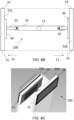
- FIGS 3A and 3B A schematic front view and plan view of an exemplary monitor support arrangement 30 is shown in more detail in FIGS 3A and 3B .
- the monitor support arrangement 30 is mounted onto a vertical mounting column 15 that is attached to the carrier 10.
- the vertical mounting column 15 has a central axis 15a, that runs longitudinally along a length of the mounting column 15.
- the monitor support arrangement 30 has a mounting bar 32 that is pivotably attached to the vertical mounting column 15 at a pivot 33.
- the pivot 33 is located at the midpoint of the mounting bar 32, and the mounting bar 32 is mounted centrally onto the vertical mounting column 15.
- the pivot 33 in FIG. 3A is therefore equidistant from either end of the mounting bar 32.
- the pivot 33 has a vertical axis 33a that is coincident with the vertical axis 15a of the vertical column 15.
- the mounting bar 32 is able to rotate (in the X-direction) around the vertical axis 33a of the pivot 33.
- the mounting bar 32 therefore is free to rotate relative to the vertical mounting column 15.
- Two carrier arms 35 are pivotable on the mounting bar 32.
- the carrier arms 35 are attached to the mounting bar 32 at the distal ends of the mounting bar 32.
- the carrier arms 35 may be positioned inboard of the distal ends of the mounting bar 32.
- the carrier arms are bars with a first end 35a that is pivotably attached to a monitor carrier 40, and a second end 35b that is pivotably attached to the mounting bar 32. More specifically, the carrier arms 35 have a first pivot 36 attached to the monitor carrier 40, and a second pivot 37 attached to the mounting bar 32.
- the first end 35a of the carrier arm 35 is attached by the first pivot 36 to the monitor carrier 40, while the second end 35b of the carrier arm 35b is attached by the second pivot 37 to the monitor bar 32.
- the monitor carrier 40 may only have the first pivot 36 or the second pivot 37.
- Each monitor carrier 40 is pivotable about the mounting bar 32.
- the first pivot 36 has a vertical axis 36a (in the y-direction) around which the monitor carrier 40 is rotatable around (in the y-direction).
- the second pivot 37 has a vertical axis 37a (in the Y-direction).
- the carrier arms 35 are rotatable around the vertical axis 37a in relation to the mounting bar 32.
- Each monitor carrier 40 is therefore independently rotatable relative to the other monitor carrier 40, carrier arm 35, and the mounting bar 32.
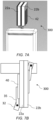
- the monitor carrier 40 is shown in greater detail in FIG. 4 .
- the monitor carrier 40 is mounted by a first pivot 36 to the first end 35a of the carrier arm 35.
- the monitor carrier 40 includes a supporting back 42 that extends perpendicularly from a base lip 41 that is arranged to receive a monitor 22a, b.
- the supporting back 42 of the monitor carrier 40 extends along a back side 24a, 24b of the monitors 22a, 22b.
- any suitable mounting arrangement may be used for the monitor carrier 40.
- each carrier arm 35 is rotatable along respective pathways 38. As shown, the carrier arms 35 are rotatable from 0° to 360° around the mounting bar 32. The diameter of the rotational pathways 38 are customizable depending on the length of the carrier arms 35. Preferably, the length of the carrier arms 35 are such that the carrier arms 35 may freely rotate from 0° to 360° without physically contacting the other carrier arm 35. The carrier arms 35 are therefore rotatable around a vertical axis 37a of the mounting bar 32 unobstructed.
- the monitors 22a, 22b are preferably also adjustable in the vertical direction, i.e. the height of the monitors 22a, 22b can be adjusted by moving the vertical column 15 in and out of the carriage 10. Since means for mounting a screen such that its vertical position is adjustable are known per se, a more detailed description of the design of such mounting means is omitted here.
- the monitor carriers 40 are mounted to the mounting bars 32 through the carrier bars 35. As the monitor carriers 40 also are rotatable around the first pivot 36, so the monitor carriers 40 effectively have a rotation of freedom of at least 90° around the first pivot 36. Preferably, the rotation of freedom of the monitor carriers 40 relative to the mounting bar pivot 30 is 180°. In other examples, the rotation of freedom of the monitor carriers may be more than 180°. In other examples, the rotation of freedom of the monitor carriers 40 relative to the mounting bar pivot 30 may be less than 180°.
- the monitor carriers 40 may preferably rotate between 0° and 360° relative to the vertical axis 33a of the mounting bar pivot 33. This enables the monitor carriers 40 to be able to be moved between a first viewing position 100, a second viewing position 200 and a stowed position 300, as discussed in greater detail below.
- FIGS 5A and 5B show perspective and plan views of the monitor support arrangement 30 and monitors 22a, 22b in the first viewing position 100.
- the monitor carriers 40 are arranged so that the monitor image screens 23a, 23b are directed in substantially similar direction.
- the monitor image screens 23a, 23b are directed towards a front side 12 of the carriage 10.
- the image screens 23a, 23b do not need to be parallel in the same direction. Instead, the majority of the image screens 23a, 23b need to be facing in a similar direction.
- the angle between the two screens is greater than 160 degrees.
- the monitor support arrangement 30 may be in the first viewing position with the image screens 23a, 23b facing towards the rear 11 of the carriage 10.
- FIGS 6A and 6B show perspective and plan views of the monitor support arrangement 30 and monitors 22a, 22b in the second viewing position 200.
- the monitor carriers 40 are arranged so that the monitor image screens 23a, 23b are directed in substantially different directions.
- one monitor image screen 23a is directed towards the front 12 of the carriage 10, while the other monitor screen 22a is directed towards the rear 11 of the carriage 10.
- the image screens 23a, 23b do not need to be 180° opposite.
- one image screen 23a may be directed towards a side of the carriage 10 (i.e. at 90° to the mounting bar 32 shown in FIG. 6B ), while the other image screen 23b may be directed towards the rear 11 of the carriage 10.
- the majority of the image screens 23a, 23b need to not be facing the same direction.
- each monitor 22a, 22b are aligned.
- the monitors 22a, 22b in this example are therefore not offset from each other.
- FIG. 6C shows an alternative arrangement of the monitor support arrangement 30 and the monitors 22a, 22b in a second viewing position 200.
- the monitor carriers are offset from each other, so that the image screens of the monitors 22a, 22b are offset from each other.
- the outer edges 24, 25 of the monitors 22a, 22b are offset from each other. Offset means that the monitors 22a, 22b and the monitor carriers are not aligned.
- the carrier arms 35 extend perpendicularly from the mounting bar 32.
- the carrier arms 35 do not extend perpendicularly from the mounting bar 32. The angle between the carrier arms 35 are reduced so that the monitors 22a, 22b can be positioned offset from each other.
- the distance between the monitors 22a, 22b is reduced.
- the second monitor 22b is positioned off the carriage 10 towards a front side 11 of the carriage.
- first monitor 22a is positioned closer to front side 11 of the carriage, and closer to the second monitor 22b.
- the first monitor 22a is therefore positioned over halfway over the upper surface 16 of the carriage 10.
- a larger area of the upper surface 16 is occupied by the monitor 22a.
- the monitor carriers 40 are rotatable relative to the mounting bar 32, it is easy for the monitors 22a, 22b to be rotated between the first and second viewing positions 100, 200.
- the mounting bar 32 and the monitor carriers 40 allow the monitors 22a, 22b to be positioned as desired. This can be particularly advantageous in areas such as operating theatres or hospital rooms as described below.
- the medical team may therefore move from viewing both monitors 22a, 22b in a first viewing position 100, before monitor support arrangement is moved into a second viewing position 200.
- the second viewing position 200 may be used for displaying and explaining medical procedures to the patient or may be used by a doctor to perform a surgical procedure.
- monitor support arrangement 30 In an operating theatre or hospital environment, it is important to maintain a sterile barrier between the patient and/or doctor and additional team members in the room, such as the nurses or students.
- monitor support arrangement 30 By having the monitor support arrangement 30 according to the present invention, it enables the doctors/patient to be present on one side of the carriage 10, while the remaining team members may be on the opposite side of the carriage. This not only maintains the sterile barrier, but also ensures that all members may view the monitors 22a, 22b.
- the monitor support arrangement 30 may be positioned into the second position 200 as shown in FIG. 6C . This may be advantageous, for example, if the doctor/team need to pull one of the monitors 22a, 22b closer for view without disrupting the view of the person on the opposite side of the carriage 10. Additionally, in this exemplary second position 200, the monitors 22a, 22b are moved towards a front side 11 of the carriage 10. The resulting unoccupied upper surface 16 may therefore be used as a storage space (for example, notebooks, medical equipment etc.) while the monitor support arrangement is in the second viewing position 200. In other examples, the monitors 22a, 22b may be moved towards the rear side 12 of the carriage 10.
- the monitor support arrangement 30 may be positioned into a stowed position 300 and put for example, in a corner of the room or a storage room. As the stowed position 300 is compact, the monitor support arrangement 30 occupies less space than conventional imaging systems or arrangements.
- FIGS 7A and 7B show perspective and plan views of the monitor support arrangement 30 and monitors 22a, 22b in the stowed position 300.
- the monitor carriers 40 are arranged so that the monitor image screens 23a, 23b are directed substantially towards each other.
- the edges of the monitor carriers 43a, 43b are aligned so that the image screens 23a, 23b of the monitors 22a, 22b are not offset from each other in the X-Y direction.
- This provides a compact arrangement as the monitors 22a, 23a may be positioned above the top surface 16 of the carriage 10 within its perimeter.
- the monitor carriers 40 are displaceable from the first viewing position 100 or second viewing position 200 to the stowed position 300 by rotation around the mounting bar 32 pivot's vertical axis 33a.
- the first monitor carrier 40 may be moved from the first viewing position 100 or second viewing position 200 to the stowed position 300 by rotating around the vertical axis 33a in a first direction by approximately 90°.
- the second monitor carrier 40 may be moved from the first viewing position 100 or second viewing position 200 to the stowed position 300 by rotating around the vertical axis 33a in a second opposite direction by approximately 90°.
- the monitor carriers 40 are therefore easily moved from either the first 100 or second viewing position 200 to the stowed position 300.
- control means 10a can be positioned towards the front side 11 of the carriage 10 while one of the monitors 22a, 22b can be rotated towards the rear side 12 of the carriage. This can be useful if the carriage 10 is used in an operating environment so that one of the monitors and control means 10a can be kept away from the sterile surgical environment. This may help prevent any bodily fluids released from the patient coming into contact with the control means 10a.
- the exemplary monitor support arrangement 30 described in relation to FIGS 1-7B is arranged to be mounted to a vertical mounting column 16 that is received in a medical apparatus 10, such as an X-ray carriage.
- a medical apparatus 10 such as an X-ray carriage.
- the monitor support arrangement 30 may be used in connection with any number of medical apparatuses, as shown in FIG. 8A .
- the monitor support apparatus 30 is used with a ceiling boom arrangement 150.
- This arrangement may be beneficial in areas such as operating theatres, where surgeons and trainee doctors or supporting nurses may need to see different image screens 23a, 23b of the monitors 22a, 22b in real time.
- the monitor support apparatus 30 may be used in non-clinical environments, as shown in FIG. 8B .
- the monitor support apparatus 30 is used with a desktop computer support arm 250.
- FIGS 9 to 13 show another exemplary embodiment of the monitor support apparatus 3000.
- the monitor support apparatus 3000 is also used with a mobile carriage 10 and is mounted to carriage 10 by a vertical mounting column 15 (shown more clearly in FIG. 11A ).
- Components of the carriage 10 and vertical mounting column 15 common to both arrangements have common reference numerals and for brevity will not be described again here.
- the monitor support arrangement 3000 is arranged to carry three substantially identical monitors, 220a, 220b, 220c.
- the monitors 220a, 220b, 220c are orientated vertically. Similar to the monitors 22a, 22b discussed above, each monitor 220a, 220b, 220c has an image screen 230a, 230b, 230c where an image is displayed, and a back side 240a, 240b, 240c opposite the image screen.
- the monitors 220a, 220b, 220c are positioned closer to the front side 11 of the carriage 10 than the back side 12.
- FIGS 11A and 11B A schematic front view and plan view of an exemplary monitor support arrangement 3000 is shown in more detail in FIGS 11A and 11B .
- the monitor support arrangement 3000 has a mounting bar 320 that is pivotably attached to the vertical mounting column 15 at a pivot 330.
- the pivot 330 has a vertical axis 330a that is coincident with the vertical axis 15a of the vertical column 15.
- the mounting bar 320 is therefore able to rotate (in the X-direction) relative to the vertical mounting column 15 around the vertical axis 330a of the pivot 330.
- the central monitor 220b is mounted on to the mounting bar 320 with a monitor carrier 400b.
- the monitor carrier 400b is arranged to attach to the monitor 220b.
- the monitor carrier 400b is a vertical rotatable column (shown more clearly in FIG. 9 in relation to the outermost monitors 220a,c).
- the monitor carrier 400b may attach directly to a lower side of the monitor 220b, or may be attached to an additional bar or support that receives the monitor 220b (not shown).
- the monitor carrier 400b has a central axis 460b and is mounted to the mounting bar 320 so that the monitor carrier 400b can rotate around the central axis 360a.
- the monitor carrier's central axis 460b is coincident with the vertical axis 15a of the vertical column 15.
- the monitor carrier 400b is able to rotate around the vertical axis 460b of the monitor carrier 400.
- the central monitor 220b may be attached through a carrier arm or may be directly attached to the mounting bar 320.
- Two carrier arms 350 are attached to the mounting bar 320 in a similar manner as described above and will not be repeated for brevity.
- Components of the carrier bars 350 common to both arrangements have common reference numerals with an addition '0' in reference to the monitor support arrangement 3000, and for brevity will not be described again here.
- the first end 350a of the carrier arm 350 is attached by the first pivot 370 to the mounting bar 320, while the second end 350b of the carrier arm 350b is attached to the monitor carriers 400a,c.
- the first pivot 370 has a vertical axis 370a (in the y-direction) around which the carrier arms 350 is rotatable around the mounting bar 320 (in the y-direction).
- Each monitor carrier 400a,c is a rotatable column that has a vertical axis 460a,c around which the monitor carrier 400 is rotatable around.
- Each monitor carrier 400a,b,c is therefore independently rotatable relative to the other monitor carrier 400a,b,c, carrier arm 350, and the mounting bar 320.
- each carrier arm 350 is rotatable along respective pathways 380, while the central monitor carrier 400b is rotatable along the pathway 382.
- the monitor arrangement 3000 operates in substantially identical way to the monitor arrangement 30 and is therefore positionable between a first viewing position 100, a second viewing position 200 and a stowed position 300.
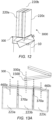
- FIG. 12 shows the monitor arrangement in greater detail in the stowed position 300, but it will be understood that the monitor carriers 400a,b,c may be rotatable so that the monitors 220a,b,c can be moved between the first, second and stowed positions 100,200,300.
- monitor support arrangement 3000 is described in relation to a carriage 10, it will be understood that similarly to the monitor support arrangement 30, the monitor support arrangement 3000 may be used in connection with a number of different medical apparatuses.
- the monitor support apparatus 3000 may be used with a ceiling boom arrangement 1500.
- the monitor support apparatus 3000 may be used in non-clinical environments, as shown in FIG. 13B .
- the monitor support apparatus 3000 is used with a desktop computer support arm 2500.
- a computer program may be stored/distributed on a suitable medium, such as an optical storage medium or a solid-state medium supplied together with or as part of other hardware, but may also be distributed in other forms, such as via the Internet or other wired or wireless telecommunication systems. Any reference signs in the claims should not be construed as limiting the scope.
Landscapes
- Engineering & Computer Science (AREA)
- General Engineering & Computer Science (AREA)
- Mechanical Engineering (AREA)
- Apparatus For Radiation Diagnosis (AREA)
Abstract
A monitor support arrangement including a mounting bar with a pivot, wherein the pivot has a vertical axis around which the mounting bar is able to rotate. The monitor support arrangement also includes two monitor carriers that are each pivotable about the mounting bar, wherein each monitor carrier is configured to receive a monitor with an image screen.
Description
- The present invention relates to a monitor support arrangement.
- Dual monitor screens and their respective mounting arrangements are typically secured to face one direction. It is difficult to easily manipulate the positioning of the monitors in other directions because monitor supports are typically rigid and generally immovable.
- This is particularly difficult in medical environments, where it may be desirable for an operator or patient to view a monitor at the same time as a surgeon performing an operation. This is difficult because there is little space in an operating theatre, so it is difficult for the surgeon to be on the same side as the operator/patient to view the monitors. It is also difficult to maintain sterility of the operating theatre in this manner as the surgeon moves from the operation field to view the screens. This leads to monitor arrangements that have cumbersome designs that are not easily viewed or transported.
- It is a general objective of the present invention to eliminate or at least reduce the above problems.
- A first aspect of the invention provides a monitor support arrangement comprising: a mounting bar with a pivot, wherein the pivot has a vertical axis around which the mounting bar is able to rotate; two monitor carriers that are each pivotable about the mounting bar, wherein each monitor carrier is configured to receive a monitor with an image screen.
- This arrangement allows the monitor carriers to be independently positioned relative to the mounting bar and the other monitor carrier.
- Optionally, the monitor carriers are configurable to be positioned in a first viewing position wherein the monitor carriers are arranged so that the monitor image screens are directed in substantially similar directions, a second viewing position wherein the monitor carriers are arranged so that the monitors have their image screens directed in substantially different directions, and a stowed position wherein the monitor carriers are arranged so that the monitors have their image screens directed substantially towards each other; and wherein the monitor carriers are displaceable between the first, second and stowed position.
- In the first viewing position, the monitor carriers are positioned in substantially similar directions when the monitor image screens are viewable from one side of the monitor support arrangement. The monitor image screens do not need to be in identical orientations to be positioned in the first viewing position.
- In the second viewing position, the monitor carriers are positioned in substantially different directions when the monitor image screens are viewable from different side of the monitor support arrangement. The monitor image screens do not need to be in opposite orientations to be positioned in the second viewing position.
- In the stowed position, the monitor carriers are positioned in substantially towards each other so that the monitor image screens are not viewable. The monitor image screens do not need to be directly opposite each other to be positioned in the stowed position.
- In the first viewing position, the monitor carriers are viewable from one side of the monitor support arrangement.
- In the second viewing position, the monitor carriers are viable from multiple sides of the monitor support arrangement so that multiple people/parties may view the monitor image screens.
- In the stowed position, the monitor carriers are positioned in a compact arrangement.
- Optionally, each monitor carrier is rotatable around a vertical axis of the mounting bar.
- The monitor carrier is arranged to maintain the orientation of the monitor image screen as the monitor carrier is rotated.
- Optionally, the monitor support arrangement further comprises at least one carrier arm between each of the monitor carriers and the mounting bar, wherein each carrier arm has a first pivot attached to the monitor carrier, and/or a second pivot attached to the mounting bar so that the monitor carriers are pivotably attached to the mounting bar by the respective carrier arms.
- The carrier arms are therefore freely rotatable relative to the mounting bar. The monitor carrier are also freely rotatable relative to the carrier arm. The rotation of the carrier arms enables the monitor carrier to be positioned in any desirable position relative to the mounting bar.
- Optionally, the first pivots of the carrier arms are inboard of an outer edge of the monitor carrier.
- Optionally, the first pivots of the carrier arms are offset from a center of the monitor carrier.
- The monitor carriers may therefore freely rotate without contacting the other monitor carrier as the monitor carriers are positioned in the first, second and stowed positioned.
- Optionally, in the stowed position, the edges of the monitor carriers are aligned so that image screens of the monitors are not offset from each other. Such "alignment" means "mostly aligned" taking into account some tolerances acceptable for the use by the user of such monitor support arrangement if used with screens for display purpose.
- The monitor support arrangement is compact in the stowed position. The monitor support arrangement therefore occupies less space in the stowed arrangement.
- Optionally, the monitor carriers are mounted to the mounting bar so as to effectively have a rotation of freedom of at least 90° around a vertical axis of the mounting bar pivot.
- Optionally, the rotation of freedom of the monitor carriers relative to the mounting bar pivot is approximately 180°.
- Optionally, the rotation freedom of the monitor carriers relative to the mounting bar pivot is substantially more than 180°.
- The monitor carriers are therefore freely positionable relative to the mounting bar. Optionally, a first one of said monitor carriers is displaceable from its first viewing position or second viewing position to its stowed position by rotation around a vertical axis with respect to the mounting bar pivot over approximately 90° in a first direction, and
wherein the second one of said monitor carriers is displaceable from its first or second viewing position to its stowed position by rotation around said vertical axis with respect to the mounting bar pivot over approximately 90° in the opposite direction. - The image screens carried by the monitor carriers are therefore viewable from opposite sides of the monitor support arrangement. This may be advantageous in arrangements where multiple people need to view the image screens carried by the monitor carriers.
- Optionally, in the second viewing position, the edges of the monitor carriers are offset so that the image screens of the monitors are offset from each other.
- The offset arrangement of the monitor carriers minimizes the distance between the monitor carriers and may be advantageous for viewing the image screens carried by the monitor carriers in space constrained environments.
- Optionally, the monitor support arrangement further comprises a third monitor carrier pivotably mounted to the mounting bar, wherein the third monitor carrier is configured to receive a monitor with an image screen.
- Optionally, the monitor support arrangement further comprises a carrier arm between the third monitor carrier and the mounting bar, wherein the carrier arm has a first pivot attached to the third monitor carrier and/or a second pivot attached to the mounting bar so that the third monitor carrier is pivotably attached to the mounting bar by the carrier arm.
- The carrier arms are freely rotatable relative to the mounting bar. The monitor carrier are also freely rotatable relative to the carrier arm. The rotation of the carrier arms enables the monitor carrier to be positioned in any desirable position relative to the mounting bar.
- Optionally, the third monitor carrier pivotably mounted to the mounting bar between the first monitor carrier and the second monitor carrier.
- Optionally, the third monitor carrier is configured to attach to a monitor with an image screen, and wherein the third monitor carrier is configurable to be positioned in a first viewing position, wherein the third monitor carrier is arranged so that the monitor image screen is directed in substantially similar directions to the monitor image screens carried by the first and/or second monitor carriers;
- a second viewing position, wherein the third monitor carrier is arranged so that the monitor image screen is directed in substantially different directions to the monitor image screens carried by the first and/or second monitor carriers; and
- a stowed position, wherein the third monitor carrier is arranged so that the monitor image screen is directed substantially towards one of the monitor image screens carried by the first and second monitor carriers; wherein the third monitor carrier is displaceable between the first, second and stowed position.
- Optionally, the monitor support system further comprises a vertical mounting column attached to an apparatus device, wherein the mounting bar is attached to the vertical mounting column so that the monitor carriers are vertically displaceable with respect to the apparatus.
- The height of the monitor support system may be changed depending on the application of the monitor support system, such as the position or the height of the people viewing the image screens.
- Optionally, the monitor arrangement is for use with an X-ray apparatus, and the monitor carriers are arranged to receive monitors with image screens for displaying X-ray images.
- The monitor support arrangement may be viewed during medical procedures. This may be advantageous in the second viewing position, as the monitor support system may be viewed by a patient and doctor simultaneously.
- Optionally, the medical apparatus is a mobile carriage, and further comprises control means including at least one human-operable control input device, for controlling the operation of an X-ray apparatus.
- Another aspect of the present invention provides a monitor support arrangement comprising a mounting bar with a pivot, wherein the pivot has a vertical axis around which the mounting bar is able to rotate, at least three monitor carriers that are pivotable on the mounting bar, wherein each monitor carrier is configured to attach to a monitor with an image screen, wherein the monitor carriers are configurable to be positioned in a first viewing position, wherein the monitor carriers are arranged so that monitor image screens are directed in the substantially same direction, a second viewing position, wherein the monitor carriers are arranged so that the monitors have their image screens directed in substantially opposite directions; and a stowed position, wherein the monitor carriers are arranged so that the monitors have their image screens directed substantially towards each other; and wherein the monitor carriers are displaceable between the first, second and stowed position.
- Optionally, each monitor carrier is rotatable around a vertical axis of the mounting bar.
- Optionally, the monitor support arrangement further comprises at least two carrier arms between at least two of the monitor carriers and the mounting bar, wherein each carrier arm has a first pivot attached to the monitor carrier, and a second pivot attached to the mounting bar so that at least two of the monitor carriers are pivotably attached to the mounting bar by the respective carrier arms.
- Optionally, the at least three monitor carriers include at least one monitor carrier pivotably attached to the mounting bar.
- These and other aspects of the invention will be apparent from and elucidated with reference to the embodiment(s) described hereinafter.
- Further features and advantages of the present invention will be described below, by way of example only, with reference to the accompanying drawings in which:
-
FIG. 1 shows an exemplary monitor support arrangement and medical apparatus; -
FIG. 2 shows a rear view of exemplary monitors; -
FIG. 3A shows a schematic front view of an exemplary monitor support arrangement; -
FIG. 3B shows a schematic plan view of an exemplary monitor support arrangement; -
FIG. 4 shows an exemplary view of a monitor carrier; -
FIGS 5A and5B show schematic views of an exemplary monitor support arrangement in a first viewing position; -
FIGS 6A to 6C show schematic views of an exemplary monitor support arrangement in a second viewing position; -
FIGS 7A and 7B show schematic views of an exemplary monitor support arrangement in a stowed position; -
FIGS 8A and 8B show further embodiments of the exemplary monitor support arrangement; -
FIG. 9 shows another exemplary monitor support arrangement; -
FIG. 10 shows a rear view of the exemplary monitor support arrangement; -
FIG. 11A shows a schematic front view of an exemplary monitor support arrangement; -
FIG. 11B shows a schematic plan view of an exemplary monitor support arrangement; -
FIG. 12 shows an exemplary monitor support arrangement in a stowed position; -
FIGS 13A and13B show further embodiments of the exemplary monitor support arrangement. -
FIGS 1 and 2 show an exemplarymobile carriage 10 for an X-ray examination apparatus, with afront side 11, aback side 12 opposite thefront side 11, and two opposite left andright sides carriage 10 haswheels 17 that are used to move thecarriage 10. Thecarriage 10 has avertical mounting column 15 that extends from anupper surface 16 of the carriage. Thecarriage 10 also includes control means 10a that includes at least one human-operable control input device, such as a keyboard. The input device may be used for controlling the operation of the X-ray examination apparatus. In this example, themobile carriage 10 has twomonitors carriage 10 by amonitor support arrangement 30. - In this example, the
carriage 10 has twomonitors monitors monitors monitors upper surface 15 of thecarriage 10. Themonitors - Each
monitor image screen back side monitors back side 12 of thecarriage 10 than thefront side 11. As will be discussed in further detail below, theimage screens monitors monitor support arrangement 30. In this example, theimage screens - A schematic front view and plan view of an exemplary
monitor support arrangement 30 is shown in more detail inFIGS 3A and 3B . As shown, themonitor support arrangement 30 is mounted onto avertical mounting column 15 that is attached to thecarrier 10. Thevertical mounting column 15 has acentral axis 15a, that runs longitudinally along a length of the mountingcolumn 15. Themonitor support arrangement 30 has a mountingbar 32 that is pivotably attached to the vertical mountingcolumn 15 at apivot 33. In this example, thepivot 33 is located at the midpoint of the mountingbar 32, and the mountingbar 32 is mounted centrally onto the vertical mountingcolumn 15. Thepivot 33 inFIG. 3A is therefore equidistant from either end of the mountingbar 32. As shown, thepivot 33 has avertical axis 33a that is coincident with thevertical axis 15a of thevertical column 15. The mountingbar 32 is able to rotate (in the X-direction) around thevertical axis 33a of thepivot 33. The mountingbar 32 therefore is free to rotate relative to the vertical mountingcolumn 15. - Two
carrier arms 35 are pivotable on the mountingbar 32. In this example, thecarrier arms 35 are attached to the mountingbar 32 at the distal ends of the mountingbar 32. In other examples, thecarrier arms 35 may be positioned inboard of the distal ends of the mountingbar 32. In the example shown inFIGS 3A and 3B , the carrier arms are bars with afirst end 35a that is pivotably attached to amonitor carrier 40, and asecond end 35b that is pivotably attached to the mountingbar 32. More specifically, thecarrier arms 35 have afirst pivot 36 attached to themonitor carrier 40, and asecond pivot 37 attached to the mountingbar 32. Thefirst end 35a of thecarrier arm 35 is attached by thefirst pivot 36 to themonitor carrier 40, while thesecond end 35b of thecarrier arm 35b is attached by thesecond pivot 37 to themonitor bar 32. In other examples, themonitor carrier 40 may only have thefirst pivot 36 or thesecond pivot 37. Eachmonitor carrier 40 is pivotable about the mountingbar 32. Thefirst pivot 36 has avertical axis 36a (in the y-direction) around which themonitor carrier 40 is rotatable around (in the y-direction). Similarly, thesecond pivot 37 has avertical axis 37a (in the Y-direction). Thecarrier arms 35 are rotatable around thevertical axis 37a in relation to the mountingbar 32. - Each
monitor carrier 40 is therefore independently rotatable relative to theother monitor carrier 40,carrier arm 35, and the mountingbar 32. - The
monitor carrier 40 is shown in greater detail inFIG. 4 . As shown, themonitor carrier 40 is mounted by afirst pivot 36 to thefirst end 35a of thecarrier arm 35. Themonitor carrier 40 includes a supporting back 42 that extends perpendicularly from abase lip 41 that is arranged to receive amonitor 22a, b. As shown more clearly inFIGS 2 and7A , the supporting back 42 of themonitor carrier 40 extends along aback side monitors monitor carrier 40. - As shown in
FIG. 3B , eachcarrier arm 35 is rotatable alongrespective pathways 38. As shown, thecarrier arms 35 are rotatable from 0° to 360° around the mountingbar 32. The diameter of therotational pathways 38 are customizable depending on the length of thecarrier arms 35. Preferably, the length of thecarrier arms 35 are such that thecarrier arms 35 may freely rotate from 0° to 360° without physically contacting theother carrier arm 35. Thecarrier arms 35 are therefore rotatable around avertical axis 37a of the mountingbar 32 unobstructed. - The
monitors monitors vertical column 15 in and out of thecarriage 10. Since means for mounting a screen such that its vertical position is adjustable are known per se, a more detailed description of the design of such mounting means is omitted here. - The
monitor carriers 40 are mounted to the mounting bars 32 through the carrier bars 35. As themonitor carriers 40 also are rotatable around thefirst pivot 36, so themonitor carriers 40 effectively have a rotation of freedom of at least 90° around thefirst pivot 36. Preferably, the rotation of freedom of themonitor carriers 40 relative to the mountingbar pivot 30 is 180°. In other examples, the rotation of freedom of the monitor carriers may be more than 180°. In other examples, the rotation of freedom of themonitor carriers 40 relative to the mountingbar pivot 30 may be less than 180°. Themonitor carriers 40 may preferably rotate between 0° and 360° relative to thevertical axis 33a of the mountingbar pivot 33. This enables themonitor carriers 40 to be able to be moved between afirst viewing position 100, asecond viewing position 200 and a stowedposition 300, as discussed in greater detail below. -
FIGS 5A and5B show perspective and plan views of themonitor support arrangement 30 andmonitors first viewing position 100. As shown more clearly inFIG. 5B , in the first viewing position themonitor carriers 40 are arranged so that themonitor image screens monitor image screens front side 12 of thecarriage 10. In order to be facing in a similar direction, it is noted that theimage screens image screens monitor support arrangement 30 may be in the first viewing position with theimage screens carriage 10. -
FIGS 6A and6B show perspective and plan views of themonitor support arrangement 30 andmonitors second viewing position 200. As shown more clearly inFIG. 6B , in the second viewing position themonitor carriers 40 are arranged so that themonitor image screens monitor image screen 23a is directed towards thefront 12 of thecarriage 10, while theother monitor screen 22a is directed towards the rear 11 of thecarriage 10. However, in order to be facing in different directions, it is noted that theimage screens image screen 23a may be directed towards a side of the carriage 10 (i.e. at 90° to the mountingbar 32 shown inFIG. 6B ), while theother image screen 23b may be directed towards the rear 11 of thecarriage 10. In order to be directed in different directions, the majority of theimage screens - In the example shown in
FIGS 6A and6B , the respectiveouter edges monitor monitors -
FIG. 6C shows an alternative arrangement of themonitor support arrangement 30 and themonitors second viewing position 200. In this example, the monitor carriers are offset from each other, so that the image screens of themonitors outer edges monitors monitors FIG. 6B , thecarrier arms 35 extend perpendicularly from the mountingbar 32. However, in the example shown inFIG. 6C , thecarrier arms 35 do not extend perpendicularly from the mountingbar 32. The angle between thecarrier arms 35 are reduced so that themonitors - As shown in
FIG. 6C , the distance between themonitors FIG. 6C , thesecond monitor 22b is positioned off thecarriage 10 towards afront side 11 of the carriage. As a result,first monitor 22a is positioned closer tofront side 11 of the carriage, and closer to thesecond monitor 22b. In this example, thefirst monitor 22a is therefore positioned over halfway over theupper surface 16 of thecarriage 10. In thesecond position 200, a larger area of theupper surface 16 is occupied by themonitor 22a. - As the
monitor carriers 40 are rotatable relative to the mountingbar 32, it is easy for themonitors bar 32 and themonitor carriers 40 allow themonitors - The medical team may therefore move from viewing both
monitors first viewing position 100, before monitor support arrangement is moved into asecond viewing position 200. Thesecond viewing position 200 may be used for displaying and explaining medical procedures to the patient or may be used by a doctor to perform a surgical procedure. - In an operating theatre or hospital environment, it is important to maintain a sterile barrier between the patient and/or doctor and additional team members in the room, such as the nurses or students. By having the
monitor support arrangement 30 according to the present invention, it enables the doctors/patient to be present on one side of thecarriage 10, while the remaining team members may be on the opposite side of the carriage. This not only maintains the sterile barrier, but also ensures that all members may view themonitors - Furthermore, the
monitor support arrangement 30 may be positioned into thesecond position 200 as shown inFIG. 6C . This may be advantageous, for example, if the doctor/team need to pull one of themonitors carriage 10. Additionally, in this exemplarysecond position 200, themonitors front side 11 of thecarriage 10. The resulting unoccupiedupper surface 16 may therefore be used as a storage space (for example, notebooks, medical equipment etc.) while the monitor support arrangement is in thesecond viewing position 200. In other examples, themonitors rear side 12 of thecarriage 10. - After use, the
monitor support arrangement 30 may be positioned into a stowedposition 300 and put for example, in a corner of the room or a storage room. As the stowedposition 300 is compact, themonitor support arrangement 30 occupies less space than conventional imaging systems or arrangements. -
FIGS 7A and 7B show perspective and plan views of themonitor support arrangement 30 andmonitors position 300. As shown more clearly inFIG. 7B , in the stowed position themonitor carriers 40 are arranged so that themonitor image screens position 300, the edges of themonitor carriers image screens monitors monitors top surface 16 of thecarriage 10 within its perimeter. - The
monitor carriers 40 are displaceable from thefirst viewing position 100 orsecond viewing position 200 to the stowedposition 300 by rotation around the mountingbar 32 pivot'svertical axis 33a. Thefirst monitor carrier 40 may be moved from thefirst viewing position 100 orsecond viewing position 200 to the stowedposition 300 by rotating around thevertical axis 33a in a first direction by approximately 90°.Thesecond monitor carrier 40 may be moved from thefirst viewing position 100 orsecond viewing position 200 to the stowedposition 300 by rotating around thevertical axis 33a in a second opposite direction by approximately 90°. Themonitor carriers 40 are therefore easily moved from either the first 100 orsecond viewing position 200 to the stowedposition 300. - With this arrangement, the control means 10a can be positioned towards the
front side 11 of thecarriage 10 while one of themonitors rear side 12 of the carriage. This can be useful if thecarriage 10 is used in an operating environment so that one of the monitors and control means 10a can be kept away from the sterile surgical environment. This may help prevent any bodily fluids released from the patient coming into contact with the control means 10a. - The exemplary
monitor support arrangement 30 described in relation toFIGS 1-7B is arranged to be mounted to avertical mounting column 16 that is received in amedical apparatus 10, such as an X-ray carriage. However, it will be understood that themonitor support arrangement 30 may be used in connection with any number of medical apparatuses, as shown inFIG. 8A . - In this example, the
monitor support apparatus 30 is used with aceiling boom arrangement 150. This arrangement may be beneficial in areas such as operating theatres, where surgeons and trainee doctors or supporting nurses may need to seedifferent image screens monitors - In other examples, the
monitor support apparatus 30 may be used in non-clinical environments, as shown inFIG. 8B . In this example, themonitor support apparatus 30 is used with a desktopcomputer support arm 250. -
FIGS 9 to 13 show another exemplary embodiment of themonitor support apparatus 3000. As shown, themonitor support apparatus 3000 is also used with amobile carriage 10 and is mounted tocarriage 10 by a vertical mounting column 15 (shown more clearly inFIG. 11A ). Components of thecarriage 10 and vertical mountingcolumn 15 common to both arrangements have common reference numerals and for brevity will not be described again here. - In this example, the
monitor support arrangement 3000 is arranged to carry three substantially identical monitors, 220a, 220b, 220c. Themonitors monitors monitor image screen back side monitors front side 11 of thecarriage 10 than theback side 12. - A schematic front view and plan view of an exemplary
monitor support arrangement 3000 is shown in more detail inFIGS 11A and 11B . Themonitor support arrangement 3000 has a mountingbar 320 that is pivotably attached to the vertical mountingcolumn 15 at apivot 330. Thepivot 330 has avertical axis 330a that is coincident with thevertical axis 15a of thevertical column 15. The mountingbar 320 is therefore able to rotate (in the X-direction) relative to the vertical mountingcolumn 15 around thevertical axis 330a of thepivot 330. - As shown, the
central monitor 220b is mounted on to the mountingbar 320 with amonitor carrier 400b. Themonitor carrier 400b is arranged to attach to themonitor 220b. In this example, themonitor carrier 400b is a vertical rotatable column (shown more clearly inFIG. 9 in relation to theoutermost monitors 220a,c). Themonitor carrier 400b may attach directly to a lower side of themonitor 220b, or may be attached to an additional bar or support that receives themonitor 220b (not shown). Themonitor carrier 400b has a central axis 460b and is mounted to the mountingbar 320 so that themonitor carrier 400b can rotate around the central axis 360a. In this example, the monitor carrier's central axis 460b is coincident with thevertical axis 15a of thevertical column 15. Themonitor carrier 400b is able to rotate around the vertical axis 460b of the monitor carrier 400. In other examples, thecentral monitor 220b may be attached through a carrier arm or may be directly attached to the mountingbar 320. - Two
carrier arms 350 are attached to the mountingbar 320 in a similar manner as described above and will not be repeated for brevity. Components of the carrier bars 350 common to both arrangements have common reference numerals with an addition '0' in reference to themonitor support arrangement 3000, and for brevity will not be described again here. - The
first end 350a of thecarrier arm 350 is attached by thefirst pivot 370 to the mountingbar 320, while thesecond end 350b of thecarrier arm 350b is attached to themonitor carriers 400a,c. Thefirst pivot 370 has a vertical axis 370a (in the y-direction) around which thecarrier arms 350 is rotatable around the mounting bar 320 (in the y-direction). Eachmonitor carrier 400a,c is a rotatable column that has avertical axis 460a,c around which the monitor carrier 400 is rotatable around. Eachmonitor carrier 400a,b,c is therefore independently rotatable relative to theother monitor carrier 400a,b,c,carrier arm 350, and the mountingbar 320. - As shown in
FIG. 11B , eachcarrier arm 350 is rotatable alongrespective pathways 380, while thecentral monitor carrier 400b is rotatable along thepathway 382. It will be understood that themonitor arrangement 3000 operates in substantially identical way to themonitor arrangement 30 and is therefore positionable between afirst viewing position 100, asecond viewing position 200 and a stowedposition 300.FIG. 12 shows the monitor arrangement in greater detail in the stowedposition 300, but it will be understood that themonitor carriers 400a,b,c may be rotatable so that themonitors 220a,b,c can be moved between the first, second and stowed positions 100,200,300. - While the
monitor support arrangement 3000 is described in relation to acarriage 10, it will be understood that similarly to themonitor support arrangement 30, themonitor support arrangement 3000 may be used in connection with a number of different medical apparatuses. For example, as shown inFIG. 13A , themonitor support apparatus 3000 may be used with aceiling boom arrangement 1500. In other examples, themonitor support apparatus 3000 may be used in non-clinical environments, as shown inFIG. 13B . In this example, themonitor support apparatus 3000 is used with a desktopcomputer support arm 2500. - Where the word 'or' appears this is to be construed to mean 'and/or' such that items referred to are not necessarily mutually exclusive and may be used in any appropriate combination.
- Although the invention has been described above with reference to one or more preferred embodiments, it will be appreciated that various changes or modifications may be made without departing from the scope of the invention as defined in the appended claims.
- While the invention has been illustrated and described in detail in the drawings and foregoing description, such illustration and description are to be considered illustrative or exemplary and not restrictive; the invention is not limited to the disclosed embodiments.
- Other variations to the disclosed embodiments can be understood and effected by those skilled in the art in practicing the claimed invention, from a study of the drawings, the disclosure, and the appended claims. In the claims, the word "comprising" does not exclude other elements or steps, and the indefinite article "a" or "an" does not exclude a plurality. A single processor or other unit may fulfill the functions of several items recited in the claims. The mere fact that certain measures are recited in mutually different dependent claims does not indicate that a combination of these measured cannot be used to advantage. A computer program may be stored/distributed on a suitable medium, such as an optical storage medium or a solid-state medium supplied together with or as part of other hardware, but may also be distributed in other forms, such as via the Internet or other wired or wireless telecommunication systems. Any reference signs in the claims should not be construed as limiting the scope.
Claims (15)
- A monitor support arrangement comprising:
a mounting bar with a pivot, wherein the pivot has a vertical axis around which the mounting bar is able to rotate;
two monitor carriers that are each pivotable about the mounting bar, wherein each monitor carrier is configured to receive a monitor with an image screen. - A monitor support arrangement according to claim 1, wherein the monitor carriers are configurable to be positioned in:a first viewing position, wherein the monitor carriers are arranged so that monitor image screens are directed in substantially similar directions;a second viewing position, wherein the monitor carriers are arranged so that the monitors have their image screens directed in substantially different directions; anda stowed position, wherein the monitor carriers are arranged so that the monitors have their image screens directed substantially towards each other; and wherein the monitor carriers are displaceable between the first, second and stowed position.
- A monitor support arrangement according to claim 1 or 2, wherein each monitor carrier is rotatable around a vertical axis of the mounting bar.
- A monitor support arrangement according to any preceding claim, wherein the monitor support arrangement further comprises at least one carrier arm between each of the monitor carriers and the mounting bar, wherein each carrier arm has a first pivot attached to the monitor carrier, and/or a second pivot attached to the mounting bar so that the monitor carriers are pivotably attached to the mounting bar by the respective carrier arms.
- A monitor support arrangement according to claim 4, wherein the first pivots of the carrier arms are inboard of an outer edge of the monitor carrier.
- A monitor support arrangement according to claim 5, wherein the first pivots of the carrier arms are offset from a center of the monitor carrier.
- A monitor support arrangement according to any preceding claim, wherein in the stowed position, the edges of monitor carriers are aligned so that the image screens of the monitors are not offset from each other.
- A monitor support arrangement according to any preceding claim, wherein a first one of said monitor carriers is displaceable from its first viewing position or second viewing position to its stowed position by rotation around a vertical axis with respect to the mounting bar pivot over approximately 90° in a first direction, and
wherein the second one of said monitor carriers is displaceable from its first or second viewing position to its stowed position by rotation around said vertical axis with respect to the mounting bar pivot over approximately 90° in the opposite direction. - A monitor support arrangement according to any preceding claim, wherein in the second viewing position, the edges of monitor carriers are offset, so that the image screens of the monitors are offset from each other.
- A monitor support arrangement according to any preceding claim, further comprising a third monitor carrier pivotably mounted to the mounting bar, wherein the third monitor carrier configured to receive a monitor with an image screen.
- A monitor support arrangement according to claim 10, wherein the monitor support arrangement further comprises a carrier arm between the third monitor carrier and the mounting bar, wherein the carrier arm has a first pivot attached to the third monitor carrier and/or a second pivot attached to the mounting bar so that the third monitor carrier is pivotably attached to the mounting bar by the carrier arm, wherein the third monitor carrier is optionally pivotably mounted to the mounting bar between the first monitor carrier and the second monitor carrier.
- A monitor support arrangement according to claim 11, wherein the third monitor carrier is configured to attach to a monitor with an image screen,and wherein the third monitor carrier is configurable to be positioned ina first viewing position, wherein the third monitor carrier is arranged so that the monitor image screen is directed in substantially similar directions to the monitor image screens carried by the first and/or second monitor carriers;a second viewing position, wherein the third monitor carrier is arranged so that the monitor image screen is directed in substantially different directions to the monitor image screens carried by the first and/or second monitor carriers; anda stowed position, wherein the third monitor carrier is arranged so that the monitor image screen is directed substantially towards one of the monitor image screens carried by the first and second monitor carriers;wherein the third monitor carrier is displaceable between the first, second and stowed position.
- A monitor support arrangement according to any preceding claim, further comprising a vertical mounting column attached to an apparatus, wherein the mounting bar is attached to the vertical mounting column so that the monitor carriers are vertically displaceable with respect to the apparatus.
- A monitor support arrangement according to claim 13, wherein the monitor arrangement is for use with an X-ray apparatus, and the monitor carriers are arranged to receive monitors with image screens for displaying X-ray images, wherein optionally the medical apparatus is a mobile carriage, and further comprises optionally control means including at least one human-operable control input device, for controlling the operation of an X-ray apparatus.
- A monitor support arrangement comprising:
a mounting bar with a pivot, wherein the pivot has a vertical axis around which the mounting bar is able to rotate;at least three monitor carriers that are pivotably attached to the mounting bar, wherein each monitor carrier is configured to attach to a monitor with an image screen;wherein the monitor carriers are configurable to be positioned in a first viewing position, wherein the monitor carriers are arranged so that monitor image screens are directed in the substantially same direction;a second viewing position, wherein the monitor carriers are arranged so that the monitors have their image screens directed in substantially opposite directions; anda stowed position, wherein the monitor carriers are arranged so that the monitors have their image screens directed substantially towards each other; and wherein the monitor carriers are displaceable between the first, second and stowed position.
Priority Applications (2)
| Application Number | Priority Date | Filing Date | Title |
|---|---|---|---|
| EP23207892.3A EP4549801A1 (en) | 2023-11-06 | 2023-11-06 | Monitor support |
| PCT/EP2024/080507 WO2025098823A1 (en) | 2023-11-06 | 2024-10-29 | Monitor support |
Applications Claiming Priority (1)
| Application Number | Priority Date | Filing Date | Title |
|---|---|---|---|
| EP23207892.3A EP4549801A1 (en) | 2023-11-06 | 2023-11-06 | Monitor support |
Publications (1)
| Publication Number | Publication Date |
|---|---|
| EP4549801A1 true EP4549801A1 (en) | 2025-05-07 |
Family
ID=88697508
Family Applications (1)
| Application Number | Title | Priority Date | Filing Date |
|---|---|---|---|
| EP23207892.3A Withdrawn EP4549801A1 (en) | 2023-11-06 | 2023-11-06 | Monitor support |
Country Status (2)
| Country | Link |
|---|---|
| EP (1) | EP4549801A1 (en) |
| WO (1) | WO2025098823A1 (en) |
Citations (6)
| Publication number | Priority date | Publication date | Assignee | Title |
|---|---|---|---|---|
| US6431751B1 (en) * | 2000-09-18 | 2002-08-13 | Koninklijke Philips Electronics N.V. | Ceiling mounted, transportable, surgical C-arm with flat panel image receptor |
| DE102005027359A1 (en) * | 2005-06-13 | 2006-11-02 | Siemens Ag | Indicator with mounting plate for several display elements e.g. monitors used in Roentgen diagnostics system, has hinges to individually support display elements as such that these are adjustable with respect to each other |
| WO2007046041A2 (en) * | 2005-10-19 | 2007-04-26 | Koninklijke Philips Electronics N. V. | X-ray examination apparatus |
| US20120056050A1 (en) * | 2010-09-03 | 2012-03-08 | Ming-Hsien Huang | Screen Supporting apparatus |
| JP2014131547A (en) * | 2013-01-07 | 2014-07-17 | Shimadzu Corp | Mobile x-ray radiographic device |
| US20150196192A1 (en) * | 2014-01-13 | 2015-07-16 | Endochoice, Inc. | Compact Monitor Stand |
Family Cites Families (4)
| Publication number | Priority date | Publication date | Assignee | Title |
|---|---|---|---|---|
| AU2597501A (en) * | 1999-12-23 | 2001-07-03 | Hill-Rom Services, Inc. | Surgical theater system |
| US7516924B2 (en) * | 2005-03-28 | 2009-04-14 | Compview Corporation | Articulated boom for positioning video and medical equipment in hospital operating rooms |
| US7644898B2 (en) * | 2005-03-28 | 2010-01-12 | Compview Medical, Llc | Medical boom with articulated arms and a base with preconfigured removable modular racks used for storing electronic and utility equipment |
| US20210251717A1 (en) * | 2020-02-19 | 2021-08-19 | Globus Medical, Inc. | Extended reality headset opacity filter for navigated surgery |
-
2023
- 2023-11-06 EP EP23207892.3A patent/EP4549801A1/en not_active Withdrawn
-
2024
- 2024-10-29 WO PCT/EP2024/080507 patent/WO2025098823A1/en active Pending
Patent Citations (6)
| Publication number | Priority date | Publication date | Assignee | Title |
|---|---|---|---|---|
| US6431751B1 (en) * | 2000-09-18 | 2002-08-13 | Koninklijke Philips Electronics N.V. | Ceiling mounted, transportable, surgical C-arm with flat panel image receptor |
| DE102005027359A1 (en) * | 2005-06-13 | 2006-11-02 | Siemens Ag | Indicator with mounting plate for several display elements e.g. monitors used in Roentgen diagnostics system, has hinges to individually support display elements as such that these are adjustable with respect to each other |
| WO2007046041A2 (en) * | 2005-10-19 | 2007-04-26 | Koninklijke Philips Electronics N. V. | X-ray examination apparatus |
| US20120056050A1 (en) * | 2010-09-03 | 2012-03-08 | Ming-Hsien Huang | Screen Supporting apparatus |
| JP2014131547A (en) * | 2013-01-07 | 2014-07-17 | Shimadzu Corp | Mobile x-ray radiographic device |
| US20150196192A1 (en) * | 2014-01-13 | 2015-07-16 | Endochoice, Inc. | Compact Monitor Stand |
Also Published As
| Publication number | Publication date |
|---|---|
| WO2025098823A1 (en) | 2025-05-15 |
Similar Documents
| Publication | Publication Date | Title |
|---|---|---|
| JP6800058B2 (en) | How to move the patient placement table | |
| US8961011B2 (en) | Mobile radiography unit having multiple monitors | |
| EP1688091B9 (en) | C-arm holding apparatus and X-ray diagnostic apparatus | |
| US7331712B2 (en) | X-ray examination apparatus that is convertible among multiple examination configurations | |
| EP3322343B1 (en) | Device for remote fluoroscopy, nearby fluoroscopy and radiology | |
| JP6752959B2 (en) | Medical system | |
| Van Det et al. | Ergonomic assessment of neck posture in the minimally invasive surgery suite during laparoscopic cholecystectomy | |
| US20140037058A1 (en) | C-Arm with Removable or Retractable Detector Housing | |
| EP2073708B1 (en) | Digital radiography imaging system | |
| US11045375B2 (en) | Robotic operating table, and robotic operating table operation device | |
| EP4549801A1 (en) | Monitor support | |
| CN101291623B (en) | X-ray inspection apparatus | |
| AU2018312101A1 (en) | Display device for reducing radiation exposure to medical personnel | |
| US11000264B2 (en) | User interface for a biopsy unit | |
| WO2014111437A1 (en) | Ceiling suspension system | |
| Siddharth et al. | Planning premises and design considerations for hybrid operating room | |
| JP2816730B2 (en) | Radiology equipment with conformable points that can move in space | |
| EP4537757A1 (en) | Holding arrangement for an x-ray imaging device | |
| JP3811017B2 (en) | Medical LCD monitor device | |
| Jahrreiss et al. | Operating Room Setup for PCNL | |
| WO2026040262A1 (en) | Surgical robot system and surgical robot arm support system thereof | |
| JPH07303653A (en) | Remote control device for medical apparatus |
Legal Events
| Date | Code | Title | Description |
|---|---|---|---|
| PUAI | Public reference made under article 153(3) epc to a published international application that has entered the european phase |
Free format text: ORIGINAL CODE: 0009012 |
|
| STAA | Information on the status of an ep patent application or granted ep patent |
Free format text: STATUS: THE APPLICATION HAS BEEN PUBLISHED |
|
| AK | Designated contracting states |
Kind code of ref document: A1 Designated state(s): AL AT BE BG CH CY CZ DE DK EE ES FI FR GB GR HR HU IE IS IT LI LT LU LV MC ME MK MT NL NO PL PT RO RS SE SI SK SM TR |
|
| STAA | Information on the status of an ep patent application or granted ep patent |
Free format text: STATUS: THE APPLICATION IS DEEMED TO BE WITHDRAWN |
|
| 18D | Application deemed to be withdrawn |
Effective date: 20251108 |