EP4549787A1 - Manifold - Google Patents
Manifold Download PDFInfo
- Publication number
- EP4549787A1 EP4549787A1 EP24206304.8A EP24206304A EP4549787A1 EP 4549787 A1 EP4549787 A1 EP 4549787A1 EP 24206304 A EP24206304 A EP 24206304A EP 4549787 A1 EP4549787 A1 EP 4549787A1
- Authority
- EP
- European Patent Office
- Prior art keywords
- housing
- valve
- manifold
- rotary valve
- accommodation portion
- Prior art date
- Legal status (The legal status is an assumption and is not a legal conclusion. Google has not performed a legal analysis and makes no representation as to the accuracy of the status listed.)
- Pending
Links
Images



Classifications
-
- F—MECHANICAL ENGINEERING; LIGHTING; HEATING; WEAPONS; BLASTING
- F16—ENGINEERING ELEMENTS AND UNITS; GENERAL MEASURES FOR PRODUCING AND MAINTAINING EFFECTIVE FUNCTIONING OF MACHINES OR INSTALLATIONS; THERMAL INSULATION IN GENERAL
- F16K—VALVES; TAPS; COCKS; ACTUATING-FLOATS; DEVICES FOR VENTING OR AERATING
- F16K11/00—Multiple-way valves, e.g. mixing valves; Pipe fittings incorporating such valves
- F16K11/10—Multiple-way valves, e.g. mixing valves; Pipe fittings incorporating such valves with two or more closure members not moving as a unit
- F16K11/20—Multiple-way valves, e.g. mixing valves; Pipe fittings incorporating such valves with two or more closure members not moving as a unit operated by separate actuating members
- F16K11/22—Multiple-way valves, e.g. mixing valves; Pipe fittings incorporating such valves with two or more closure members not moving as a unit operated by separate actuating members with an actuating member for each valve, e.g. interconnected to form multiple-way valves
-
- F—MECHANICAL ENGINEERING; LIGHTING; HEATING; WEAPONS; BLASTING
- F16—ENGINEERING ELEMENTS AND UNITS; GENERAL MEASURES FOR PRODUCING AND MAINTAINING EFFECTIVE FUNCTIONING OF MACHINES OR INSTALLATIONS; THERMAL INSULATION IN GENERAL
- F16K—VALVES; TAPS; COCKS; ACTUATING-FLOATS; DEVICES FOR VENTING OR AERATING
- F16K11/00—Multiple-way valves, e.g. mixing valves; Pipe fittings incorporating such valves
- F16K11/02—Multiple-way valves, e.g. mixing valves; Pipe fittings incorporating such valves with all movable sealing faces moving as one unit
- F16K11/08—Multiple-way valves, e.g. mixing valves; Pipe fittings incorporating such valves with all movable sealing faces moving as one unit comprising only taps or cocks
- F16K11/085—Multiple-way valves, e.g. mixing valves; Pipe fittings incorporating such valves with all movable sealing faces moving as one unit comprising only taps or cocks with cylindrical plug
-
- F—MECHANICAL ENGINEERING; LIGHTING; HEATING; WEAPONS; BLASTING
- F16—ENGINEERING ELEMENTS AND UNITS; GENERAL MEASURES FOR PRODUCING AND MAINTAINING EFFECTIVE FUNCTIONING OF MACHINES OR INSTALLATIONS; THERMAL INSULATION IN GENERAL
- F16K—VALVES; TAPS; COCKS; ACTUATING-FLOATS; DEVICES FOR VENTING OR AERATING
- F16K11/00—Multiple-way valves, e.g. mixing valves; Pipe fittings incorporating such valves
- F16K11/02—Multiple-way valves, e.g. mixing valves; Pipe fittings incorporating such valves with all movable sealing faces moving as one unit
- F16K11/08—Multiple-way valves, e.g. mixing valves; Pipe fittings incorporating such valves with all movable sealing faces moving as one unit comprising only taps or cocks
- F16K11/083—Multiple-way valves, e.g. mixing valves; Pipe fittings incorporating such valves with all movable sealing faces moving as one unit comprising only taps or cocks with tapered plug
- F16K11/0836—Multiple-way valves, e.g. mixing valves; Pipe fittings incorporating such valves with all movable sealing faces moving as one unit comprising only taps or cocks with tapered plug having all the connecting conduits situated in more than one plane perpendicular to the axis of the plug
-
- F—MECHANICAL ENGINEERING; LIGHTING; HEATING; WEAPONS; BLASTING
- F16—ENGINEERING ELEMENTS AND UNITS; GENERAL MEASURES FOR PRODUCING AND MAINTAINING EFFECTIVE FUNCTIONING OF MACHINES OR INSTALLATIONS; THERMAL INSULATION IN GENERAL
- F16K—VALVES; TAPS; COCKS; ACTUATING-FLOATS; DEVICES FOR VENTING OR AERATING
- F16K11/00—Multiple-way valves, e.g. mixing valves; Pipe fittings incorporating such valves
- F16K11/02—Multiple-way valves, e.g. mixing valves; Pipe fittings incorporating such valves with all movable sealing faces moving as one unit
- F16K11/08—Multiple-way valves, e.g. mixing valves; Pipe fittings incorporating such valves with all movable sealing faces moving as one unit comprising only taps or cocks
- F16K11/085—Multiple-way valves, e.g. mixing valves; Pipe fittings incorporating such valves with all movable sealing faces moving as one unit comprising only taps or cocks with cylindrical plug
- F16K11/0856—Multiple-way valves, e.g. mixing valves; Pipe fittings incorporating such valves with all movable sealing faces moving as one unit comprising only taps or cocks with cylindrical plug having all the connecting conduits situated in more than one plane perpendicular to the axis of the plug
-
- F—MECHANICAL ENGINEERING; LIGHTING; HEATING; WEAPONS; BLASTING
- F16—ENGINEERING ELEMENTS AND UNITS; GENERAL MEASURES FOR PRODUCING AND MAINTAINING EFFECTIVE FUNCTIONING OF MACHINES OR INSTALLATIONS; THERMAL INSULATION IN GENERAL
- F16K—VALVES; TAPS; COCKS; ACTUATING-FLOATS; DEVICES FOR VENTING OR AERATING
- F16K27/00—Construction of housing; Use of materials therefor
- F16K27/06—Construction of housing; Use of materials therefor of taps or cocks
- F16K27/065—Construction of housing; Use of materials therefor of taps or cocks with cylindrical plugs
-
- F—MECHANICAL ENGINEERING; LIGHTING; HEATING; WEAPONS; BLASTING
- F16—ENGINEERING ELEMENTS AND UNITS; GENERAL MEASURES FOR PRODUCING AND MAINTAINING EFFECTIVE FUNCTIONING OF MACHINES OR INSTALLATIONS; THERMAL INSULATION IN GENERAL
- F16K—VALVES; TAPS; COCKS; ACTUATING-FLOATS; DEVICES FOR VENTING OR AERATING
- F16K5/00—Plug valves; Taps or cocks comprising only cut-off apparatus having at least one of the sealing faces shaped as a more or less complete surface of a solid of revolution, the opening and closing movement being predominantly rotary
- F16K5/04—Plug valves; Taps or cocks comprising only cut-off apparatus having at least one of the sealing faces shaped as a more or less complete surface of a solid of revolution, the opening and closing movement being predominantly rotary with plugs having cylindrical surfaces; Packings therefor
- F16K5/0457—Packings
- F16K5/0471—Packings between housing and plug
Definitions
- the present disclosure relates to a manifold.
- HEV hybrid electric vehicle
- PHEV plug-in hybrid electric vehicle
- BEV battery electric vehicle
- FCEV fuel cell electric vehicle
- electric vehicles there are many devices that require cooling, such as a motor (including an internal combustion engine such as an engine), a battery, an air conditioner, and an ECU. Therefore, a cooling circuit that circulates a coolant, a refrigerant, and oil is configured to cool these devices. At this time, by forming the flow path of the cooling circuit in the manifold, routing of the pipe can be eliminated to simplify the flow path configuration, and the cooling circuit can be downsized.
- WO 2023/104347 A discloses a manifold in which two housings are joined and a valve accommodation portion is formed in each housing to house a control valve.
- the height of the manifold is required to be equal to or higher than the height of the control valve. That is, the height of the manifold is constrained by the height of the control valve, and there is room for improvement.
- One embodiment of a manifold according to the present disclosure includes a resin-made manifold main body including a plurality of housings joined to each other and having a plurality of flow paths therein, and a rotary valve that regulates a flow of a fluid flowing through the flow paths, wherein a first housing that is one of two housings having joint portions joined to each other among the plurality of housings constituting the manifold main body includes a cylindrical valve accommodation portion that is allowed to accommodate and support the rotary valve, and wherein at least part of the valve accommodation portion protrudes toward a second housing side relative to the joint portions, the second housing being the other of the two housings.
- At least part of the valve accommodation portion formed in the first housing protrudes toward the second housing side relative to the joint portion.
- the height of the manifold main body can be reduced, as compared with a configuration in which at least part of the valve accommodation portion formed in the first housing does not protrude toward the second housing side relative to the joint portion.
- a manifold 300 is used for electric vehicles that are an automobile (hybrid electric vehicle (HEV), a plug-in hybrid electric vehicle (PHEV), a battery electric vehicle (BEV), a fuel cell electric vehicle (FCEV), and the like including a motor as a traveling drive source.
- the manifold 300 is formed by integrating a motor (including an internal combustion engine such as an engine), a flow path for circulating a coolant (an example of a fluid) for cooling a device requiring cooling, such as a battery, an air conditioner, and an ECU, a rotary valve that regulates a flow of the coolant, and a water pump that pumps the coolant of an electric vehicle.
- a motor including an internal combustion engine such as an engine
- a flow path for circulating a coolant an example of a fluid
- a device requiring cooling such as a battery, an air conditioner, and an ECU
- a rotary valve that regulates a flow of the coolant
- a water pump that pumps the coolant of
- the manifold 300 includes a first rotary valve 340 (an example of a rotary valve), a second rotary valve 350 (an example of a rotary valve), a first water pump 360, a second water pump 370, and a manifold main body 302 in which a plurality of flow paths 312 for circulating a coolant therethrough is formed.
- the manifold main body 302 is formed by joining and integrating a plurality of housings by a method such as welding, and in the present embodiment, as shown in Fig. 3 , the manifold main body is formed by joining a first housing 310 (an example of a housing) and a second housing 330 (an example of a housing).
- the coolant includes cooling water such as a long life coolant (LLC) or insulating oil such as paraffin.
- the plurality of flow paths 312 illustrated in Figs. 1 to 3 is a concept including both an inflow path through which the coolant flows into the first rotary valve 340 or the second rotary valve 350 and an outflow path through which the coolant flows out from the first rotary valve 340 or the second rotary valve 350.
- the plurality of flow paths 312 is a concept including all flow paths through which the coolant flows the inside of the manifold main body 302, such as a flow path formed only in the first housing 310, a flow path formed only in the second housing 330, and a flow path formed across the first housing 310 to the second housing 330.
- a plurality of (five in the present embodiment) first flow paths 312a is disposed on a side close to the second housing 330 and a plurality of (four in the present embodiment) second flow paths 312b is disposed on a side far from the second housing 330 in a direction along the rotation axis AX (an example of the central axis) of each of the first rotary valve 340 and the second rotary valve 350.
- the flow path 312 is a general term for the first flow path 312a and the second flow path 312b.
- the protruding directions of the nine flow paths 312 are all perpendicular to the rotation axis AX (see Fig. 2 ).
- a direction (height direction) parallel to the rotation axis AX is referred to as a "Z direction".
- Z direction a direction of the first housing 310 with respect to the second housing 330
- Z2 direction a direction of the second housing 330 with respect to the first housing 310
- the first rotary valve 340, the second rotary valve 350, the first water pump 360, and the second water pump 370 are all attached to the first housing 310.
- the first rotary valve 340 and the first water pump 360 are disposed adjacent to each other, and the second rotary valve 350 and the second water pump 370 are disposed adjacent to each other.
- the rotation axis AX of the first rotary valve 340 and the rotation axis AX of the second rotary valve 350 are parallel to each other
- the rotation axis BX of the first water pump 360 and the rotation axis BX of the second water pump 370 are parallel to each other.
- the rotation axis AX of the first rotary valve 340 and the second rotary valve 350 and the rotation axis BX of the first water pump 360 and the second water pump 370 are perpendicular to each other.
- the second housing 330 only some of the plurality of flow paths 312 is formed (see Fig. 3 ).
- the first rotary valve 340 includes a first actuator 341 (an example of a lid), a first valve body 342 (an example of a rotor), and a first seal member 343 (an example of a seal member).
- the second rotary valve 350 includes a second actuator 351 (an example of a lid), a second valve body 352 (an example of a rotor), and a second seal member 353 (an example of a seal member).
- the first actuator 341 and the second actuator 351 are fixed to the first housing 310 in a state of being exposed to the surface of the first housing 310.
- the first valve body 342 and the first seal member 343 are accommodated in a first valve chamber 316 (an example of a valve accommodation portion) formed in the first housing 310.
- the second valve body 352 and the second seal member 353 are accommodated in a second valve chamber 318 (an example of a valve accommodation portion) formed in the first housing 310.
- the first valve chamber 316 and the second valve chamber 318 are disposed in a central region 310b (see Fig. 3 ) located between the pair of opposing outer walls 310a of the first housing 310 and between the first water pump 360 and the second water pump 370.
- a plurality of spare chambers 314 is formed around each of the first valve chamber 316 and the second valve chamber 318 of the first housing 310.
- the plurality of spare chambers 314 is formed between the flow path 312 and the first valve chamber 316 and between the flow path 312 and the second valve chamber 318, and the flow path 312 and the first valve chamber 316 communicate with each other and the flow path 312 and the second valve chamber 318 communicate with each other via the spare chamber 314.
- the spare chamber 314 is a concept including both an inflow spare chamber connected to the inflow path and an outflow spare chamber connected to the outflow path.
- the spare chamber 314 is disposed in all the flow paths 312 communicating with the first valve chamber 316 and in all the flow paths 312 communicating with the second valve chamber 318.
- the plurality of flow paths 312 and the plurality of spare chambers 314 are radially disposed so as to surround each of the first valve chamber 316 and the second valve chamber 318.
- a first partition wall 324 (an example of a joint portion) that partitions two adjacent ones of the flow path 312, the first valve chamber 316, the second valve chamber 318, the spare chamber 314, a first vortex chamber 320 (see Fig. 2 ), and a second vortex chamber 322 is formed.
- the first housing 310 includes only the flow path 312, the first valve chamber 316, the second valve chamber 318, the spare chamber 314, the first vortex chamber 320, the second vortex chamber 322, and the first partition wall 324.
- a second partition wall 332 (an example of a joint portion) that partitions two adjacent ones of some of the plurality of flow paths 312 and the spare chamber 314 formed in the second housing 330 is formed.
- the manifold main body 302 is formed by joining the first partition wall 324 of the first housing 310 and the second partition wall 332 of the second housing 330 by a method such as welding.
- the first valve chamber 316 formed in the first housing 310 has a bottomed cylindrical shape having a first opening 316a (an example of an opening), a first side wall 316b, and a first bottom wall 316c (an example of a bottom wall) (see Fig. 4 ).
- the central axis of the first valve chamber 316 is coaxial with the rotation axis AX in a state where the first rotary valve 340 is accommodated. That is, the central axis of the first valve chamber 316 is also the rotation axis AX.
- the inner diameter of the first valve chamber 316 is formed to decrease from the first opening 316a toward the first bottom wall 316c.
- the first side wall 316b has a tapered shape extending in the Z2 direction.
- the first valve body 342 and the first seal member 343 of the first rotary valve 340 can be smoothly inserted into the first valve chamber 316 from the first opening 316a.
- the first valve body 342 and the first seal member 343 can be reliably positioned in the Z direction with respect to the first valve chamber 316.
- a first through hole 334 is formed at a position, of the second housing 330, facing the first valve chamber 316, and part of the first side wall 316b of the first valve chamber 316 and the first bottom wall 316c are fitted into the first through hole 334 of the second housing 330 by joining the first housing 310 and the second housing 330.
- the first bottom wall 316c does not protrude below (in the Z2 direction) the second housing 330.
- the second valve chamber 318 has a bottomed cylindrical shape having a second opening 318a (an example of an opening), a second side wall 318b, and a second bottom wall 318c (an example of a bottom wall).
- the central axis of the second valve chamber 318 is coaxial with the rotation axis AX in a state where the second rotary valve 350 is accommodated. That is, the central axis of the second valve chamber 318 is also the rotation axis AX.
- the inner diameter of the second valve chamber 318 is formed to decrease from the second opening 318a toward the second bottom wall 318c. That is, the second side wall 318b has a tapered shape extending in the Z2 direction.
- the second valve body 352 and the second seal member 353 of the second rotary valve 350 can be smoothly inserted into the second valve chamber 318 from the second opening 318a.
- the second valve body 352 and the second seal member 353 can be reliably positioned in the Z direction with respect to the second valve chamber 318.
- a second through hole 335 is formed at a position, of the second housing 330, facing the second valve chamber 318, and part of the second side wall 318b of the second valve chamber 318 and the second bottom wall 318c are fitted into the second through hole 335 of the second housing 330 by joining the first housing 310 and the second housing 330.
- the second bottom wall 318c does not protrude below (in the Z2 direction) the second housing 330.
- These protruding portions are fitted into the first through hole 334 and the second through hole 335 of the second housing 330, respectively, in a state where the first housing 310 and the second housing 330 are joined.
- the first valve body 342 is accommodated in the first valve chamber 316 of the first housing 310, and the first actuator 341 is fixed to the first housing 310 to cover the first opening 316a.
- one end portion of a first rotation shaft 342a of the first valve body 342 is connected to the first actuator 341, and the other end portion is supported by a first bush 316f formed on the first bottom wall 316c (see Fig. 4 ).
- the rotation axis AX tends to be parallel to the Z direction, as compared with the configuration in which the first rotation shaft 342a is supported by the first housing 310 and the second housing 330, thereby realizing smooth rotation of the first valve body 342.
- the second valve body 352 is accommodated in the second valve chamber 318 of the first housing 310, and the second actuator 351 is fixed to the first housing 310 to cover the second opening 318a.
- one end portion of a second rotation shaft 352a of the second valve body 352 is connected to the second actuator 351, and the other end portion is supported by a second bush (not illustrated) formed on the second bottom wall 318c.
- the rotation axis AX tends to be parallel to the Z direction, as compared with the configuration in which the second rotation shaft 352a is supported by the first housing 310 and the second housing 330, thereby realizing smooth rotation of the second valve body 352.
- the first housing 310 includes a plurality of (four in the present embodiment) stays 326 (an example of fixing portions) for fixing the manifold 300 to the support frame 380 of the electric vehicle.
- the stay 326 extends in the Z2 direction.
- first rotary valve 340 and the second rotary valve 350 have the same configuration except for the configurations of the first valve body 342 and the second valve body 352 that switch the flow path 312 (see Fig. 2 ). Therefore, only the configuration of the first rotary valve 340 will be described below, and a detailed description of the configuration of the second rotary valve 350 will be omitted.
- the first seal member 343 is disposed so as to be in contact with the first side wall 316b and the first bottom wall 316c of the first valve chamber 316.
- the first valve body 342 is disposed radially inside the first seal member 343 so as to be in contact with the first seal member 343.
- the first valve body 342 has a columnar shape (see Fig. 2 ), and a flow path is formed therein.
- the first rotation shaft 342a of the first valve body 342 is disposed so as to be coaxial with the rotation axis AX in a state where the first valve body 342 is accommodated in the first valve chamber 316.
- One end portion of the first rotation shaft 342a is connected to the first actuator 341, and rotates the first rotation shaft 342a by driving the first actuator 341 to rotate the first valve body 342.
- the other end of the first rotation shaft 342a is supported by the first bush 316f formed on the first bottom wall 316c.
- the first rotary valve 340 can regulate the flow of the cooling water flowing through the flow path 312.
- the first seal member 343 does not rotate when the first valve body 342 rotates. Since the first valve body 342 and the first seal member 343 are in contact with each other, the first valve body 342 rotates while sliding on the inner peripheral face of the first seal member 343.
- the first seal member 343 is disposed over substantially the entire circumference in the circumferential direction of the first valve chamber 316.
- the first seal member 343 is not disposed over the entire circumference of the first valve chamber 316 in the circumferential direction (not annular), and has a substantially C shape that does not has part thereof in the circumferential direction in plan view (when viewed in the Z direction) (see Fig. 2 ).
- the entire first seal member 343 in the circumferential direction is also referred to as "over the entire circumference".
- the first seal member 343 is elastically deformable, and is sandwiched between the first valve chamber 316 and the first valve body 342 and compressed in the radial direction to seal the flow path and prevent the coolant from leaking from the flow path.
- the first seal member 343 is formed of an elastically deformable rubber material such as nitrile rubber (NBR), fluororubber (FKM), or urethane rubber (U).
- the first seal member 343 has a plurality of flow ports 343a at positions corresponding to the plurality of spare chambers 314 (flow paths 312) formed around the first valve chamber 316 of the first housing 310. Accordingly, the cooling water can flow between the spare chamber 314 and the first valve body 342 while ensuring the sealing property.
- An upper rib 344 and a lower rib 345 are formed at both ends of the first seal member 343 along the Z direction over the entire circumference (see Fig. 2 ).
- the upper rib 344 and the lower rib 345 extend along the Z direction and have a substantially cylindrical shape when viewed in the Z direction.
- a plurality of rotation stoppers 345a extends in the Z2 direction from the distal end of the lower rib 345. In the present embodiment, a total of three rotation stoppers 345a are disposed at about every 120 degrees.
- annular upper groove 341a (an example of a groove) is formed around the rotation axis AX when viewed in the Z direction.
- the upper groove 341a may not have an annular shape when viewed in the Z direction, but may have a substantially C shape into which the upper rib 344 is fitted without a gap.
- An annular lower groove 316d (an example of a groove) is formed in the first bottom wall 316c of the first valve chamber 316 around the rotation axis AX when viewed in the Z direction.
- the lower groove 316d sandwiches and holds the lower rib 345.
- the lower groove 316d may not have an annular shape when viewed in the Z direction, and may have a substantially C shape into which the lower rib 345 is fitted without a gap.
- a plurality of (three in the present embodiment) stopper grooves 316e into which the rotation stopper 345a is inserted is formed in the bottom of the lower groove 316d formed in the first bottom wall 316c of the first valve chamber 316.
- the stopper groove 316e has such a size that the rotation stopper 345a is fitted without a gap.
- the first seal member 343 has the upper rib 344 and the lower rib 345 at both ends along the Z direction, and the upper rib 344 and the lower rib 345 are sandwiched between the upper groove 341a and the lower groove 316d, respectively. Therefore, the first seal member 343 is positioned in the Z direction, and the first seal member 343 can be prevented from falling down due to an external force, rotation of the first valve body 342, or the like. Further, since the rotation stopper 345a is fitted in the stopper groove 316e, even when the first valve body 342 rotates while sliding on the inner peripheral face of the first seal member 343, the first seal member 343 can be prevented from co-rotating.
- the manifold 300 is supported by being fixed to a support frame 380 of the electric vehicle by a method such as fastening a stay 326 with a bolt 382.
- first housing 310 of the manifold main body 302 As described above, four stays 326 are disposed in the first housing 310 of the manifold main body 302 (see Fig. 3 ).
- various auxiliary machines such as the first rotary valve 340, the second rotary valve 350, the first water pump 360, and the second water pump 370 are attached to the first housing 310, while only some of the plurality of flow paths 312 are formed in the second housing 330 (see Figs. 1 and 3 ). Therefore, the first housing 310 to which various auxiliary machines are attached is much heavier than the second housing 330.
- the first housing 310 to which various auxiliary machines are attached is supported at a position where the first partition wall 324 of the first housing 310 and the second partition wall 332 of the second housing 330 are joined by a method such as welding. That is, since the center of gravity of the manifold 300 is located at a position on the first housing 310 side rather than a portion where the first housing 310 and the second housing 330 are joined to each other, a force for releasing the joining acts on the joined portion due to the weight of the first housing 310 to which various auxiliary machines are attached.
- vibration, impact, or the like during traveling of the electric vehicle acts on the joint portion in such a state, in the worst case, there is a possibility that the joint is released and the first housing 310 falls off.
- the manifold 300 of the present embodiment since the stay 326 is disposed in the first housing 310 to which various auxiliary machines are attached, the heavy first housing 310 is directly fixed to the support frame 380. Therefore, the force in the direction in which the joint acting on the joint portion between the first partition wall 324 of the first housing 310 and the second partition wall 332 of the second housing 330 is released is only due to the weight of the lightweight second housing 330. Therefore, even when vibration, impact, or the like during traveling of the electric vehicle acts on the joint portion, there is little possibility that the joint is released and the second housing 330 falls off. Therefore, the manifold 300 can be reliably fixed to the support frame 380.
- At least part of the valve accommodation portion (316, 318) formed in the first housing (310) protrudes toward the second housing (330) side relative to the joint portions (324, 332).
- the height of the manifold main body (302) can be reduced, as compared with a configuration in which at least part of the valve accommodation portion (316, 318) formed in the first housing (310) does not protrude toward the second housing (330) side relative to the joint portions (324, 332).
- the valve accommodation portion (316, 318) preferably has an opening (316a, 318a) into which the rotary valve (340, 350) is allowed to be inserted and a bottom wall (316c, 318c) that is allowed to support the rotary valve (340, 350), and an inner diameter of the valve accommodation portion (316, 318) preferably decreases from an opening (316a, 318a) side toward a bottom wall (316c, 318c) side.
- the rotary valve (340, 350) can be smoothly inserted into the valve accommodation portion (316, 318) from the opening (316a, 318a).
- the rotary valve (340, 350) can be reliably positioned with respect to the valve accommodation portion (316, 318).
- the manifold (300) according to Item (2) preferably further includes a lid (341, 351) that covers the opening (316a, 318a) and is fixed to the first housing (310), the rotary valve (340, 350) preferably includes a rotor (342, 352) that rotates about a central axis (AX) of the valve accommodation portion (316, 318) to regulate a flow of the fluid, and a seal member (343, 353) disposed between the rotor (342, 352) and the valve accommodation portion (316, 318), at least one of the bottom wall (316c, 318c) and the lid (341, 351) of the valve accommodation portion (316, 318) preferably has a groove (316d, 341a) around the central axis (AX), and the seal member (343, 353) is preferably held by being inserted into the groove (316d, 341a).
- At least one of the bottom wall (316c, 318c) and the lid (341, 351) of the valve accommodation portion (316, 318) of the first housing (310) has the groove (316d, 341a) around the central axis (AX), and the seal member (343, 353) of the rotary valve (340, 350) is held by being inserted into the groove (316d, 341a). Therefore, the seal member (343, 353) is positioned in the height direction, and the seal member (343, 353) can be prevented from falling down due to an external force, rotation of the rotor (342, 352), or the like.
- the first housing (310) preferably includes a fixing portion (326) fixed to a support frame (380).
- the fixing portion (326) is disposed in the first housing (310) which accommodates the rotary valve (340, 350), the first housing (310) is directly fixed to the support frame (380). Therefore, the force in the direction in which the joint acting on the joint portion between the first housing (310) and the second housing (330) is released is only due to the weight of the second housing (330) that is lighter than the first housing (310). Therefore, even when unintended vibration, impact, or the like acts on the joint portion, there is little possibility that the joint is released and the second housing (330) falls off, and the manifold (300) can be reliably fixed to the support frame (380).
- the present disclosure is applicable to a manifold.
Landscapes
- Engineering & Computer Science (AREA)
- General Engineering & Computer Science (AREA)
- Mechanical Engineering (AREA)
- Valve Housings (AREA)
Abstract
A manifold (300) includes a resin-made manifold main body (302) including a plurality of housings (310, 330) joined to each other and having a plurality of flow paths therein, and a rotary valve (340) that regulates a flow of a fluid flowing through the flow paths, wherein a first housing (310) that is one of two housings having joint portions (324, 332) joined to each other among the plurality of housings (310, 330) constituting the manifold main body (302) includes a cylindrical valve accommodation portion (316) that is allowed to accommodate and support the rotary valve (340), and wherein at least part of the valve accommodation portion (316) protrudes toward a second housing (330) side relative to the joint portions (324, 332), the second housing (330) being the other of the two housings.
Description
- The present disclosure relates to a manifold.
- In recent years, an automobile (hybrid electric vehicle (HEV), a plug-in hybrid electric vehicle (PHEV), a battery electric vehicle (BEV), a fuel cell electric vehicle (FCEV), and the like including a motor as a traveling drive source have been widely used. Hereinafter, these automobiles are collectively referred to as electric vehicles. In an electric vehicle, there are many devices that require cooling, such as a motor (including an internal combustion engine such as an engine), a battery, an air conditioner, and an ECU. Therefore, a cooling circuit that circulates a coolant, a refrigerant, and oil is configured to cool these devices. At this time, by forming the flow path of the cooling circuit in the manifold, routing of the pipe can be eliminated to simplify the flow path configuration, and the cooling circuit can be downsized.
-
WO 2023/104347 A discloses a manifold in which two housings are joined and a valve accommodation portion is formed in each housing to house a control valve. - In the manifold of
WO 2023/104347 A , since two housings are joined to form a valve accommodation portion in each housing to house a control valve, the height of the manifold is required to be equal to or higher than the height of the control valve. That is, the height of the manifold is constrained by the height of the control valve, and there is room for improvement. - A need thus exists for a manifold that is hardly constrained by the valve height.
- One embodiment of a manifold according to the present disclosure includes a resin-made manifold main body including a plurality of housings joined to each other and having a plurality of flow paths therein, and a rotary valve that regulates a flow of a fluid flowing through the flow paths, wherein a first housing that is one of two housings having joint portions joined to each other among the plurality of housings constituting the manifold main body includes a cylindrical valve accommodation portion that is allowed to accommodate and support the rotary valve, and wherein at least part of the valve accommodation portion protrudes toward a second housing side relative to the joint portions, the second housing being the other of the two housings.
- According to the present embodiment, at least part of the valve accommodation portion formed in the first housing protrudes toward the second housing side relative to the joint portion. With this configuration, the height of the manifold main body can be reduced, as compared with a configuration in which at least part of the valve accommodation portion formed in the first housing does not protrude toward the second housing side relative to the joint portion. As a result, it is possible to provide a manifold that is hardly constrained by the height of the rotary valve.
- The foregoing and additional features and characteristics of this disclosure will become more apparent from the following detailed description considered with the reference to the accompanying drawings, wherein:
-
Fig. 1 is a perspective view illustrating a manifold according to the present embodiment; -
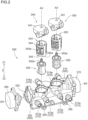
Fig. 2 is an exploded perspective view of a manifold; -
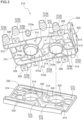
Fig. 3 is an exploded perspective view of a manifold main body; -
Fig. 4 is a cross-sectional view taken along line IV-IV inFig. 1 ; and -
Fig. 5 is a side view illustrating a manifold in a state of being fixed to a support frame. - Hereinafter, embodiments of a manifold according to the present disclosure will be described in detail with reference to the drawings. Note that the embodiments described below are examples for describing the present disclosure, and the present disclosure is not limited only to these embodiments. Therefore, the present disclosure can be implemented in various forms without departing from the gist thereof.
- A
manifold 300 according to the present embodiment is used for electric vehicles that are an automobile (hybrid electric vehicle (HEV), a plug-in hybrid electric vehicle (PHEV), a battery electric vehicle (BEV), a fuel cell electric vehicle (FCEV), and the like including a motor as a traveling drive source. Themanifold 300 is formed by integrating a motor (including an internal combustion engine such as an engine), a flow path for circulating a coolant (an example of a fluid) for cooling a device requiring cooling, such as a battery, an air conditioner, and an ECU, a rotary valve that regulates a flow of the coolant, and a water pump that pumps the coolant of an electric vehicle. - As shown in
Fig. 1 , themanifold 300 includes a first rotary valve 340 (an example of a rotary valve), a second rotary valve 350 (an example of a rotary valve), afirst water pump 360, asecond water pump 370, and a manifoldmain body 302 in which a plurality offlow paths 312 for circulating a coolant therethrough is formed. The manifoldmain body 302 is formed by joining and integrating a plurality of housings by a method such as welding, and in the present embodiment, as shown inFig. 3 , the manifold main body is formed by joining a first housing 310 (an example of a housing) and a second housing 330 (an example of a housing). The coolant includes cooling water such as a long life coolant (LLC) or insulating oil such as paraffin. - The plurality of
flow paths 312 illustrated inFigs. 1 to 3 is a concept including both an inflow path through which the coolant flows into the firstrotary valve 340 or the secondrotary valve 350 and an outflow path through which the coolant flows out from the firstrotary valve 340 or the secondrotary valve 350. The plurality offlow paths 312 is a concept including all flow paths through which the coolant flows the inside of the manifoldmain body 302, such as a flow path formed only in thefirst housing 310, a flow path formed only in thesecond housing 330, and a flow path formed across thefirst housing 310 to thesecond housing 330. - In the
flow path 312 having a portion protruding outward from theouter wall 310a of thefirst housing 310 in theflow path 312 in the present embodiment, a plurality of (five in the present embodiment)first flow paths 312a is disposed on a side close to thesecond housing 330 and a plurality of (four in the present embodiment)second flow paths 312b is disposed on a side far from thesecond housing 330 in a direction along the rotation axis AX (an example of the central axis) of each of the firstrotary valve 340 and the secondrotary valve 350. Theflow path 312 is a general term for thefirst flow path 312a and thesecond flow path 312b. The protruding directions of the nineflow paths 312 are all perpendicular to the rotation axis AX (seeFig. 2 ). Hereinafter, a direction (height direction) parallel to the rotation axis AX is referred to as a "Z direction". In the Z direction, a direction of thefirst housing 310 with respect to thesecond housing 330 is referred to as a Z1 direction, and a direction of thesecond housing 330 with respect to thefirst housing 310 is referred to as a Z2 direction. - In the manifold
main body 302 of the present embodiment, the firstrotary valve 340, the secondrotary valve 350, thefirst water pump 360, and thesecond water pump 370 are all attached to thefirst housing 310. The firstrotary valve 340 and thefirst water pump 360 are disposed adjacent to each other, and the secondrotary valve 350 and thesecond water pump 370 are disposed adjacent to each other. As illustrated inFig. 2 , the rotation axis AX of the firstrotary valve 340 and the rotation axis AX of the secondrotary valve 350 are parallel to each other, and the rotation axis BX of thefirst water pump 360 and the rotation axis BX of thesecond water pump 370 are parallel to each other. The rotation axis AX of the firstrotary valve 340 and the secondrotary valve 350 and the rotation axis BX of thefirst water pump 360 and thesecond water pump 370 are perpendicular to each other. In thesecond housing 330, only some of the plurality offlow paths 312 is formed (seeFig. 3 ). - As illustrated in
Figs. 1 and2 , the firstrotary valve 340 includes a first actuator 341 (an example of a lid), a first valve body 342 (an example of a rotor), and a first seal member 343 (an example of a seal member). The secondrotary valve 350 includes a second actuator 351 (an example of a lid), a second valve body 352 (an example of a rotor), and a second seal member 353 (an example of a seal member). Thefirst actuator 341 and thesecond actuator 351 are fixed to thefirst housing 310 in a state of being exposed to the surface of thefirst housing 310. Thefirst valve body 342 and thefirst seal member 343 are accommodated in a first valve chamber 316 (an example of a valve accommodation portion) formed in thefirst housing 310. Thesecond valve body 352 and thesecond seal member 353 are accommodated in a second valve chamber 318 (an example of a valve accommodation portion) formed in thefirst housing 310. Thefirst valve chamber 316 and thesecond valve chamber 318 are disposed in acentral region 310b (seeFig. 3 ) located between the pair of opposingouter walls 310a of thefirst housing 310 and between thefirst water pump 360 and thesecond water pump 370. - As illustrated in
Fig. 3 , a plurality ofspare chambers 314 is formed around each of thefirst valve chamber 316 and thesecond valve chamber 318 of thefirst housing 310. The plurality ofspare chambers 314 is formed between theflow path 312 and thefirst valve chamber 316 and between theflow path 312 and thesecond valve chamber 318, and theflow path 312 and thefirst valve chamber 316 communicate with each other and theflow path 312 and thesecond valve chamber 318 communicate with each other via thespare chamber 314. Thespare chamber 314 is a concept including both an inflow spare chamber connected to the inflow path and an outflow spare chamber connected to the outflow path. In the present embodiment, thespare chamber 314 is disposed in all theflow paths 312 communicating with thefirst valve chamber 316 and in all theflow paths 312 communicating with thesecond valve chamber 318. The plurality offlow paths 312 and the plurality ofspare chambers 314 are radially disposed so as to surround each of thefirst valve chamber 316 and thesecond valve chamber 318. - In the
first housing 310, a first partition wall 324 (an example of a joint portion) that partitions two adjacent ones of theflow path 312, thefirst valve chamber 316, thesecond valve chamber 318, thespare chamber 314, a first vortex chamber 320 (seeFig. 2 ), and asecond vortex chamber 322 is formed. Thefirst housing 310 includes only theflow path 312, thefirst valve chamber 316, thesecond valve chamber 318, thespare chamber 314, thefirst vortex chamber 320, thesecond vortex chamber 322, and thefirst partition wall 324. - In the
second housing 330, a second partition wall 332 (an example of a joint portion) that partitions two adjacent ones of some of the plurality offlow paths 312 and thespare chamber 314 formed in thesecond housing 330 is formed. The manifoldmain body 302 is formed by joining thefirst partition wall 324 of thefirst housing 310 and thesecond partition wall 332 of thesecond housing 330 by a method such as welding. - As illustrated in
Figs. 2 and3 , thefirst valve chamber 316 formed in thefirst housing 310 has a bottomed cylindrical shape having afirst opening 316a (an example of an opening), afirst side wall 316b, and afirst bottom wall 316c (an example of a bottom wall) (seeFig. 4 ). The central axis of thefirst valve chamber 316 is coaxial with the rotation axis AX in a state where the firstrotary valve 340 is accommodated. That is, the central axis of thefirst valve chamber 316 is also the rotation axis AX. The inner diameter of thefirst valve chamber 316 is formed to decrease from the first opening 316a toward thefirst bottom wall 316c. That is, thefirst side wall 316b has a tapered shape extending in the Z2 direction. As a result, thefirst valve body 342 and thefirst seal member 343 of the firstrotary valve 340 can be smoothly inserted into thefirst valve chamber 316 from thefirst opening 316a. In addition, thefirst valve body 342 and thefirst seal member 343 can be reliably positioned in the Z direction with respect to thefirst valve chamber 316. - Part of the
first side wall 316b of thefirst valve chamber 316 and the firstbottom wall 316c protrude below (in the Z2 direction) thefirst partition wall 324. That is, part of thefirst side wall 316b and the firstbottom wall 316c protrude toward thesecond housing 330 side relative to thefirst partition wall 324. A first throughhole 334 is formed at a position, of thesecond housing 330, facing thefirst valve chamber 316, and part of thefirst side wall 316b of thefirst valve chamber 316 and the firstbottom wall 316c are fitted into the first throughhole 334 of thesecond housing 330 by joining thefirst housing 310 and thesecond housing 330. The firstbottom wall 316c does not protrude below (in the Z2 direction) thesecond housing 330. - Similarly, the
second valve chamber 318 has a bottomed cylindrical shape having asecond opening 318a (an example of an opening), asecond side wall 318b, and a secondbottom wall 318c (an example of a bottom wall). The central axis of thesecond valve chamber 318 is coaxial with the rotation axis AX in a state where the secondrotary valve 350 is accommodated. That is, the central axis of thesecond valve chamber 318 is also the rotation axis AX. The inner diameter of thesecond valve chamber 318 is formed to decrease from thesecond opening 318a toward the secondbottom wall 318c. That is, thesecond side wall 318b has a tapered shape extending in the Z2 direction. As a result, thesecond valve body 352 and thesecond seal member 353 of the secondrotary valve 350 can be smoothly inserted into thesecond valve chamber 318 from thesecond opening 318a. In addition, thesecond valve body 352 and thesecond seal member 353 can be reliably positioned in the Z direction with respect to thesecond valve chamber 318. - Part of the
second side wall 318b of thesecond valve chamber 318 and the secondbottom wall 318c protrude below (in the Z2 direction) thefirst partition wall 324. That is, part of thesecond side wall 318b and the secondbottom wall 318c protrude toward thesecond housing 330 side relative to thefirst partition wall 324. A second throughhole 335 is formed at a position, of thesecond housing 330, facing thesecond valve chamber 318, and part of thesecond side wall 318b of thesecond valve chamber 318 and the secondbottom wall 318c are fitted into the second throughhole 335 of thesecond housing 330 by joining thefirst housing 310 and thesecond housing 330. The secondbottom wall 318c does not protrude below (in the Z2 direction) thesecond housing 330. - In the present embodiment, part of the
first side wall 316b and the firstbottom wall 316c of thefirst valve chamber 316, and part of thesecond side wall 318b and the secondbottom wall 318c of thesecond valve chamber 318 protrude below thefirst partition wall 324. These protruding portions are fitted into the first throughhole 334 and the second throughhole 335 of thesecond housing 330, respectively, in a state where thefirst housing 310 and thesecond housing 330 are joined. With such a configuration, a length (height) of the manifoldmain body 302 along the Z direction can be shortened, as compared with a configuration in which thefirst valve chamber 316 and thesecond valve chamber 318 do not protrude below thefirst partition wall 324. As a result, the manifold 300 can be downsized. - In the present embodiment, the
first valve body 342 is accommodated in thefirst valve chamber 316 of thefirst housing 310, and thefirst actuator 341 is fixed to thefirst housing 310 to cover thefirst opening 316a. As a result, one end portion of afirst rotation shaft 342a of thefirst valve body 342 is connected to thefirst actuator 341, and the other end portion is supported by afirst bush 316f formed on the firstbottom wall 316c (seeFig. 4 ). As described above, by supporting both ends of thefirst rotation shaft 342a by thefirst actuator 341 fixed to thefirst housing 310 and thefirst bush 316f formed in thefirst housing 310, the rotation axis AX tends to be parallel to the Z direction, as compared with the configuration in which thefirst rotation shaft 342a is supported by thefirst housing 310 and thesecond housing 330, thereby realizing smooth rotation of thefirst valve body 342. - The
second valve body 352 is accommodated in thesecond valve chamber 318 of thefirst housing 310, and thesecond actuator 351 is fixed to thefirst housing 310 to cover thesecond opening 318a. As a result, one end portion of asecond rotation shaft 352a of thesecond valve body 352 is connected to thesecond actuator 351, and the other end portion is supported by a second bush (not illustrated) formed on the secondbottom wall 318c. As described above, by supporting both ends of thesecond rotation shaft 352a by thesecond actuator 351 fixed to thefirst housing 310 and the second bush formed in thefirst housing 310, the rotation axis AX tends to be parallel to the Z direction, as compared with the configuration in which thesecond rotation shaft 352a is supported by thefirst housing 310 and thesecond housing 330, thereby realizing smooth rotation of thesecond valve body 352. - As illustrated in
Figs. 1 to 3 and5 , thefirst housing 310 includes a plurality of (four in the present embodiment) stays 326 (an example of fixing portions) for fixing the manifold 300 to thesupport frame 380 of the electric vehicle. Thestay 326 extends in the Z2 direction. - Next, configurations of the first
rotary valve 340 and the secondrotary valve 350 will be described. In the present embodiment, the firstrotary valve 340 and the secondrotary valve 350 have the same configuration except for the configurations of thefirst valve body 342 and thesecond valve body 352 that switch the flow path 312 (seeFig. 2 ). Therefore, only the configuration of the firstrotary valve 340 will be described below, and a detailed description of the configuration of the secondrotary valve 350 will be omitted. - As illustrated in
Fig. 4 , in the firstrotary valve 340, thefirst seal member 343 is disposed so as to be in contact with thefirst side wall 316b and the firstbottom wall 316c of thefirst valve chamber 316. Thefirst valve body 342 is disposed radially inside thefirst seal member 343 so as to be in contact with thefirst seal member 343. - The
first valve body 342 has a columnar shape (seeFig. 2 ), and a flow path is formed therein. Thefirst rotation shaft 342a of thefirst valve body 342 is disposed so as to be coaxial with the rotation axis AX in a state where thefirst valve body 342 is accommodated in thefirst valve chamber 316. One end portion of thefirst rotation shaft 342a is connected to thefirst actuator 341, and rotates thefirst rotation shaft 342a by driving thefirst actuator 341 to rotate thefirst valve body 342. The other end of thefirst rotation shaft 342a is supported by thefirst bush 316f formed on the firstbottom wall 316c. By rotating thefirst valve body 342, the combination of theflow path 312 of the cooling water flowing into thefirst valve chamber 316 and theflow path 312 of the cooling water flowing out from thefirst valve chamber 316 can be changed. In this manner, the firstrotary valve 340 can regulate the flow of the cooling water flowing through theflow path 312. In the firstrotary valve 340, thefirst seal member 343 does not rotate when thefirst valve body 342 rotates. Since thefirst valve body 342 and thefirst seal member 343 are in contact with each other, thefirst valve body 342 rotates while sliding on the inner peripheral face of thefirst seal member 343. - The
first seal member 343 is disposed over substantially the entire circumference in the circumferential direction of thefirst valve chamber 316. To be precise, thefirst seal member 343 is not disposed over the entire circumference of thefirst valve chamber 316 in the circumferential direction (not annular), and has a substantially C shape that does not has part thereof in the circumferential direction in plan view (when viewed in the Z direction) (seeFig. 2 ). However, in the following description, the entirefirst seal member 343 in the circumferential direction is also referred to as "over the entire circumference". Thefirst seal member 343 is elastically deformable, and is sandwiched between thefirst valve chamber 316 and thefirst valve body 342 and compressed in the radial direction to seal the flow path and prevent the coolant from leaking from the flow path. Thefirst seal member 343 is formed of an elastically deformable rubber material such as nitrile rubber (NBR), fluororubber (FKM), or urethane rubber (U). - The
first seal member 343 has a plurality offlow ports 343a at positions corresponding to the plurality of spare chambers 314 (flow paths 312) formed around thefirst valve chamber 316 of thefirst housing 310. Accordingly, the cooling water can flow between thespare chamber 314 and thefirst valve body 342 while ensuring the sealing property. - An
upper rib 344 and alower rib 345 are formed at both ends of thefirst seal member 343 along the Z direction over the entire circumference (seeFig. 2 ). Theupper rib 344 and thelower rib 345 extend along the Z direction and have a substantially cylindrical shape when viewed in the Z direction. In thelower rib 345, a plurality ofrotation stoppers 345a extends in the Z2 direction from the distal end of thelower rib 345. In the present embodiment, a total of threerotation stoppers 345a are disposed at about every 120 degrees. - As illustrated in
Fig. 4 , in a face, of thefirst actuator 341, facing thefirst valve chamber 316, an annular upper groove 341a (an example of a groove) is formed around the rotation axis AX when viewed in the Z direction. By inserting theupper rib 344 of thefirst seal member 343 into the upper groove 341a, the upper groove 341a sandwiches and holds theupper rib 344. The upper groove 341a may not have an annular shape when viewed in the Z direction, but may have a substantially C shape into which theupper rib 344 is fitted without a gap. - An annular
lower groove 316d (an example of a groove) is formed in the firstbottom wall 316c of thefirst valve chamber 316 around the rotation axis AX when viewed in the Z direction. By inserting thelower rib 345 of thefirst seal member 343 into thelower groove 316d, thelower groove 316d sandwiches and holds thelower rib 345. Thelower groove 316d may not have an annular shape when viewed in the Z direction, and may have a substantially C shape into which thelower rib 345 is fitted without a gap. - In the bottom of the
lower groove 316d formed in the firstbottom wall 316c of thefirst valve chamber 316, a plurality of (three in the present embodiment)stopper grooves 316e into which therotation stopper 345a is inserted is formed. Thestopper groove 316e has such a size that therotation stopper 345a is fitted without a gap. By inserting thelower rib 345 into thelower groove 316d in a state where therotation stopper 345a of thefirst seal member 343 and thestopper groove 316e of the firstbottom wall 316c are aligned, thelower groove 316d and thestopper groove 316e can sandwich and hold thelower rib 345 and therotation stopper 345a. At this time, theflow port 343a of thefirst seal member 343 faces thespare chamber 314 formed around thefirst valve chamber 316. - In the first
rotary valve 340 of the present embodiment, thefirst seal member 343 has theupper rib 344 and thelower rib 345 at both ends along the Z direction, and theupper rib 344 and thelower rib 345 are sandwiched between the upper groove 341a and thelower groove 316d, respectively. Therefore, thefirst seal member 343 is positioned in the Z direction, and thefirst seal member 343 can be prevented from falling down due to an external force, rotation of thefirst valve body 342, or the like. Further, since therotation stopper 345a is fitted in thestopper groove 316e, even when thefirst valve body 342 rotates while sliding on the inner peripheral face of thefirst seal member 343, thefirst seal member 343 can be prevented from co-rotating. - Next, a method of supporting the manifold 300 in the electric vehicle will be described with reference to
Fig. 5 . The manifold 300 is supported by being fixed to asupport frame 380 of the electric vehicle by a method such as fastening astay 326 with abolt 382. - As described above, four stays 326 are disposed in the
first housing 310 of the manifold main body 302 (seeFig. 3 ). In the present embodiment, various auxiliary machines such as the firstrotary valve 340, the secondrotary valve 350, thefirst water pump 360, and thesecond water pump 370 are attached to thefirst housing 310, while only some of the plurality offlow paths 312 are formed in the second housing 330 (seeFigs. 1 and3 ). Therefore, thefirst housing 310 to which various auxiliary machines are attached is much heavier than thesecond housing 330. - In a case where the
stay 326 is disposed in thesecond housing 330 in the manifold 300, when the manifold 300 is fixed to thesupport frame 380 in a posture as illustrated inFig. 5 , thefirst housing 310 to which various auxiliary machines are attached is supported at a position where thefirst partition wall 324 of thefirst housing 310 and thesecond partition wall 332 of thesecond housing 330 are joined by a method such as welding. That is, since the center of gravity of the manifold 300 is located at a position on thefirst housing 310 side rather than a portion where thefirst housing 310 and thesecond housing 330 are joined to each other, a force for releasing the joining acts on the joined portion due to the weight of thefirst housing 310 to which various auxiliary machines are attached. When vibration, impact, or the like during traveling of the electric vehicle acts on the joint portion in such a state, in the worst case, there is a possibility that the joint is released and thefirst housing 310 falls off. - However, in the
manifold 300 of the present embodiment, since thestay 326 is disposed in thefirst housing 310 to which various auxiliary machines are attached, the heavyfirst housing 310 is directly fixed to thesupport frame 380. Therefore, the force in the direction in which the joint acting on the joint portion between thefirst partition wall 324 of thefirst housing 310 and thesecond partition wall 332 of thesecond housing 330 is released is only due to the weight of the lightweightsecond housing 330. Therefore, even when vibration, impact, or the like during traveling of the electric vehicle acts on the joint portion, there is little possibility that the joint is released and thesecond housing 330 falls off. Therefore, the manifold 300 can be reliably fixed to thesupport frame 380. -
- <1> In the above embodiment, the
first valve chamber 316 and thesecond valve chamber 318 are covered with thefirst actuator 341 and thesecond actuator 351, respectively, but may be covered with another one that is not an actuator. In this case, an actuator for rotating thefirst valve body 342 and thesecond valve body 352 may be separately disposed outside the lid. - <2> In the above embodiment, the first through
hole 334 and the second throughhole 335 into which the firstbottom wall 316c of thefirst valve chamber 316 and the secondbottom wall 318c of thesecond valve chamber 318 of thefirst housing 310 are fitted are formed in thesecond housing 330, but they are not necessarily through holes. Instead of the through hole, a bottomed recess may be formed in thesecond housing 330, and each of the firstbottom wall 316c and the secondbottom wall 318c may be fitted into the recess. - <3> In the above embodiment, the first
bottom wall 316c and the secondbottom wall 318c are configured not to protrude below thesecond housing 330, but may be configured to protrude below thesecond housing 330. - <4> In the above embodiment, the
first seal member 343 is fixed to thefirst valve chamber 316 by theupper rib 344 and thelower rib 345, but may be configured to be fixed to thefirst valve chamber 316 by any one of theupper rib 344 and thelower rib 345. The same applies to thesecond seal member 353. - <5> In the above embodiment, the
rotation stopper 345a of thefirst seal member 343 is formed only on thelower rib 345, but the present invention is not limited thereto. Therotation stopper 345a may be configured to be formed on theupper rib 344 instead of thelower rib 345 or together with thelower rib 345. The same applies to thesecond seal member 353. - <6> In the above embodiment, the manifold
main body 302 is configured by thefirst housing 310 and thesecond housing 330, but may be configured by combining three or more housings. - In the embodiment of the manifold 300 described above, the following configuration is conceived.
- (1) An aspect of a manifold (300) includes a resin-made manifold main body (302) including a plurality of housings (310, 330) joined to each other and having a plurality of flow paths (312) therein, and a rotary valve (340, 350) that regulates a flow of a fluid flowing through the flow paths (312), a first housing (310) that is one of two housings having joint portions (324, 332) joined to each other among the plurality of housings (310, 330) constituting the manifold main body (302) includes a cylindrical valve accommodation portion (316, 318) that is allowed to accommodate and support the rotary valve (340, 350), and at least part of the valve accommodation portion (316, 318) protrudes toward a second housing (330) side relative to the joint portions (324, 332), the second housing (330) being the other of the two housings.
- In the aspect, at least part of the valve accommodation portion (316, 318) formed in the first housing (310) protrudes toward the second housing (330) side relative to the joint portions (324, 332). With this configuration, the height of the manifold main body (302) can be reduced, as compared with a configuration in which at least part of the valve accommodation portion (316, 318) formed in the first housing (310) does not protrude toward the second housing (330) side relative to the joint portions (324, 332). As a result, it is possible to provide the manifold (300) which is hardly constrained by the height of the rotary valve (340, 350).
- (2) In the manifold (300) according to Item (1), the valve accommodation portion (316, 318) preferably has an opening (316a, 318a) into which the rotary valve (340, 350) is allowed to be inserted and a bottom wall (316c, 318c) that is allowed to support the rotary valve (340, 350), and an inner diameter of the valve accommodation portion (316, 318) preferably decreases from an opening (316a, 318a) side toward a bottom wall (316c, 318c) side.
- With this configuration, the rotary valve (340, 350) can be smoothly inserted into the valve accommodation portion (316, 318) from the opening (316a, 318a). In addition, the rotary valve (340, 350) can be reliably positioned with respect to the valve accommodation portion (316, 318).
- (3) The manifold (300) according to Item (2) preferably further includes a lid (341, 351) that covers the opening (316a, 318a) and is fixed to the first housing (310), the rotary valve (340, 350) preferably includes a rotor (342, 352) that rotates about a central axis (AX) of the valve accommodation portion (316, 318) to regulate a flow of the fluid, and a seal member (343, 353) disposed between the rotor (342, 352) and the valve accommodation portion (316, 318), at least one of the bottom wall (316c, 318c) and the lid (341, 351) of the valve accommodation portion (316, 318) preferably has a groove (316d, 341a) around the central axis (AX), and the seal member (343, 353) is preferably held by being inserted into the groove (316d, 341a).
- With this configuration, at least one of the bottom wall (316c, 318c) and the lid (341, 351) of the valve accommodation portion (316, 318) of the first housing (310) has the groove (316d, 341a) around the central axis (AX), and the seal member (343, 353) of the rotary valve (340, 350) is held by being inserted into the groove (316d, 341a). Therefore, the seal member (343, 353) is positioned in the height direction, and the seal member (343, 353) can be prevented from falling down due to an external force, rotation of the rotor (342, 352), or the like.
- (4) In the manifold (300) according to any one of Items (1) to (3), the first housing (310) preferably includes a fixing portion (326) fixed to a support frame (380).
- With this configuration, since the fixing portion (326) is disposed in the first housing (310) which accommodates the rotary valve (340, 350), the first housing (310) is directly fixed to the support frame (380). Therefore, the force in the direction in which the joint acting on the joint portion between the first housing (310) and the second housing (330) is released is only due to the weight of the second housing (330) that is lighter than the first housing (310). Therefore, even when unintended vibration, impact, or the like acts on the joint portion, there is little possibility that the joint is released and the second housing (330) falls off, and the manifold (300) can be reliably fixed to the support frame (380).
- The present disclosure is applicable to a manifold.
- It is explicitly stated that all features disclosed in the description and/or the claims are intended to be disclosed separately and independently from each other for the purpose of original disclosure as well as for the purpose of restricting the claimed invention independent of the composition of the features in the embodiments and/or the claims. It is explicitly stated that all value ranges or indications of groups of entities disclose every possible intermediate value or intermediate entity for the purpose of original disclosure as well as for the purpose of restricting the claimed invention, in particular as limits of value ranges.
Claims (5)
- A manifold (300) comprising:a resin-made manifold main body (302) including a plurality of housings (310, 330) joined to each other and having a plurality of flow paths (312) therein; anda rotary valve (340, 350) that regulates a flow of a fluid flowing through the flow paths (312), whereina first housing (310) that is one of two housings having joint portions (324, 332) joined to each other among the plurality of housings (310, 330) constituting the manifold main body (302) includes a cylindrical valve accommodation portion (316, 318) that is allowed to accommodate and support the rotary valve (340, 350), and whereinat least part of the valve accommodation portion (316, 318) protrudes toward a second housing (330) side relative to the joint portions (324, 332), the second housing (330) being the other of the two housings.
- The manifold (300) according to Claim 1, whereinthe valve accommodation portion (316, 318) has an opening (316a, 318a) into which the rotary valve (340, 350) is allowed to be inserted and a bottom wall (316c, 318c) that is allowed to support the rotary valve (340, 350), and whereinthe second housing (330) has a through hole (334, 335), and the bottom wall (316c, 318c) is disposed radially inside the through hole (334, 335) of the second housing (330).
- The manifold (300) according to Claim 2, wherein an inner diameter of the valve accommodation portion (316, 318) decreases from an opening (316a, 318a) side toward a bottom wall (316c, 318c) side.
- The manifold (300) according to Claim 2 or 3 further comprising:a lid (341, 351) that covers the opening (316a, 318a) and is fixed to the first housing (310), whereinthe rotary valve (340, 350) includes a rotor (342, 352) that rotates about a central axis (AX) of the valve accommodation portion (316, 318) to regulate a flow of the fluid, and a seal member (343, 353) disposed between the rotor (342, 352) and the valve accommodation portion (316, 318), whereinat least one of the bottom wall (316c, 318c) and the lid (341, 351) of the valve accommodation portion (316, 318) has a groove (316d, 341a) around the central axis (AX), and whereinthe seal member (343, 353) is held by being inserted into the groove (316d, 341a).
- The manifold (300) according to any one of Claims 1 to 4, wherein the first housing (310) includes a fixing portion (326) fixed to a support frame (380).
Applications Claiming Priority (1)
| Application Number | Priority Date | Filing Date | Title |
|---|---|---|---|
| JP2023185951A JP2025074865A (en) | 2023-10-30 | 2023-10-30 | Manifold |
Publications (1)
| Publication Number | Publication Date |
|---|---|
| EP4549787A1 true EP4549787A1 (en) | 2025-05-07 |
Family
ID=93119682
Family Applications (1)
| Application Number | Title | Priority Date | Filing Date |
|---|---|---|---|
| EP24206304.8A Pending EP4549787A1 (en) | 2023-10-30 | 2024-10-14 | Manifold |
Country Status (4)
| Country | Link |
|---|---|
| US (1) | US20250137540A1 (en) |
| EP (1) | EP4549787A1 (en) |
| JP (1) | JP2025074865A (en) |
| CN (1) | CN119914713A (en) |
Citations (7)
| Publication number | Priority date | Publication date | Assignee | Title |
|---|---|---|---|---|
| US10288178B2 (en) * | 2015-09-29 | 2019-05-14 | Kerr Machine Co. | Sealing high pressure flow devices |
| CN111706691A (en) * | 2020-07-07 | 2020-09-25 | 合肥学院 | A regulating valve with various flow characteristics |
| US20200318750A1 (en) * | 2017-12-19 | 2020-10-08 | Halliburton Energy Services, Inc. | Enhanced design for plug valve |
| WO2022143866A1 (en) * | 2020-12-31 | 2022-07-07 | 浙江三花汽车零部件有限公司 | Fluid control valve |
| WO2023079088A1 (en) * | 2021-11-08 | 2023-05-11 | Eto Magnetic Gmbh | Fluid seal system, fluid circuit, and method |
| WO2023104347A1 (en) | 2021-12-06 | 2023-06-15 | HELLA GmbH & Co. KGaA | Coolant distributor assembly with control valve for multiple coolant circuits |
| US20230235832A1 (en) * | 2022-01-21 | 2023-07-27 | Vitesco Technologies USA, LLC | Multi-port thermal module |
-
2023
- 2023-10-30 JP JP2023185951A patent/JP2025074865A/en active Pending
-
2024
- 2024-10-10 US US18/911,653 patent/US20250137540A1/en active Pending
- 2024-10-14 EP EP24206304.8A patent/EP4549787A1/en active Pending
- 2024-10-29 CN CN202411517622.1A patent/CN119914713A/en active Pending
Patent Citations (7)
| Publication number | Priority date | Publication date | Assignee | Title |
|---|---|---|---|---|
| US10288178B2 (en) * | 2015-09-29 | 2019-05-14 | Kerr Machine Co. | Sealing high pressure flow devices |
| US20200318750A1 (en) * | 2017-12-19 | 2020-10-08 | Halliburton Energy Services, Inc. | Enhanced design for plug valve |
| CN111706691A (en) * | 2020-07-07 | 2020-09-25 | 合肥学院 | A regulating valve with various flow characteristics |
| WO2022143866A1 (en) * | 2020-12-31 | 2022-07-07 | 浙江三花汽车零部件有限公司 | Fluid control valve |
| WO2023079088A1 (en) * | 2021-11-08 | 2023-05-11 | Eto Magnetic Gmbh | Fluid seal system, fluid circuit, and method |
| WO2023104347A1 (en) | 2021-12-06 | 2023-06-15 | HELLA GmbH & Co. KGaA | Coolant distributor assembly with control valve for multiple coolant circuits |
| US20230235832A1 (en) * | 2022-01-21 | 2023-07-27 | Vitesco Technologies USA, LLC | Multi-port thermal module |
Also Published As
| Publication number | Publication date |
|---|---|
| JP2025074865A (en) | 2025-05-14 |
| CN119914713A (en) | 2025-05-02 |
| US20250137540A1 (en) | 2025-05-01 |
Similar Documents
| Publication | Publication Date | Title |
|---|---|---|
| US9650943B2 (en) | Rotary valve | |
| JP7490059B2 (en) | Valves, batteries and power consuming devices | |
| US10344883B2 (en) | Modular electro-mechanical rotary valve | |
| US10968810B2 (en) | Thermal management module | |
| US11698140B2 (en) | Ball valve with multi-angular sealing for coolant control regulator | |
| US12344070B2 (en) | Valve device with multiple flow passages | |
| WO2022070839A1 (en) | Valve device | |
| US20250137540A1 (en) | Manifold | |
| WO2019022116A1 (en) | Motor | |
| KR20250057636A (en) | Drive apparatus | |
| JP6977803B2 (en) | Motor assembly | |
| CN113795654A (en) | Control valve | |
| KR102564923B1 (en) | Radial multi-valve for electric vehicle coolant | |
| WO2024142750A1 (en) | Fluid control valve | |
| KR102784168B1 (en) | Scroll compressor | |
| JP2015090128A (en) | Intake control valve and its assembling method | |
| JP2024095128A (en) | Fluid Control Valve | |
| CN115133720A (en) | Drive device | |
| KR20240018104A (en) | Fluid valve | |
| EP4491919A1 (en) | Cooling module | |
| US20250383022A1 (en) | Coolant control valve | |
| EP4641055A1 (en) | Rotary valve | |
| EP4717952A1 (en) | Manifold | |
| US20260132735A1 (en) | Cooling module | |
| US20250379493A1 (en) | Electric machine with a stator assembly and immersion cooling system |
Legal Events
| Date | Code | Title | Description |
|---|---|---|---|
| PUAI | Public reference made under article 153(3) epc to a published international application that has entered the european phase |
Free format text: ORIGINAL CODE: 0009012 |
|
| STAA | Information on the status of an ep patent application or granted ep patent |
Free format text: STATUS: THE APPLICATION HAS BEEN PUBLISHED |
|
| AK | Designated contracting states |
Kind code of ref document: A1 Designated state(s): AL AT BE BG CH CY CZ DE DK EE ES FI FR GB GR HR HU IE IS IT LI LT LU LV MC ME MK MT NL NO PL PT RO RS SE SI SK SM TR |
|
| STAA | Information on the status of an ep patent application or granted ep patent |
Free format text: STATUS: REQUEST FOR EXAMINATION WAS MADE |
|
| 17P | Request for examination filed |
Effective date: 20251009 |