EP4549784A1 - Stop valve - Google Patents
Stop valve Download PDFInfo
- Publication number
- EP4549784A1 EP4549784A1 EP23830077.6A EP23830077A EP4549784A1 EP 4549784 A1 EP4549784 A1 EP 4549784A1 EP 23830077 A EP23830077 A EP 23830077A EP 4549784 A1 EP4549784 A1 EP 4549784A1
- Authority
- EP
- European Patent Office
- Prior art keywords
- valve
- opening
- valve body
- connecting pipe
- valve core
- Prior art date
- Legal status (The legal status is an assumption and is not a legal conclusion. Google has not performed a legal analysis and makes no representation as to the accuracy of the status listed.)
- Pending
Links
Images




Classifications
-
- F—MECHANICAL ENGINEERING; LIGHTING; HEATING; WEAPONS; BLASTING
- F16—ENGINEERING ELEMENTS AND UNITS; GENERAL MEASURES FOR PRODUCING AND MAINTAINING EFFECTIVE FUNCTIONING OF MACHINES OR INSTALLATIONS; THERMAL INSULATION IN GENERAL
- F16K—VALVES; TAPS; COCKS; ACTUATING-FLOATS; DEVICES FOR VENTING OR AERATING
- F16K1/00—Lift valves or globe valves, i.e. cut-off apparatus with closure members having at least a component of their opening and closing motion perpendicular to the closing faces
- F16K1/32—Details
- F16K1/34—Cutting-off parts, e.g. valve members, seats
- F16K1/36—Valve members
-
- F—MECHANICAL ENGINEERING; LIGHTING; HEATING; WEAPONS; BLASTING
- F16—ENGINEERING ELEMENTS AND UNITS; GENERAL MEASURES FOR PRODUCING AND MAINTAINING EFFECTIVE FUNCTIONING OF MACHINES OR INSTALLATIONS; THERMAL INSULATION IN GENERAL
- F16K—VALVES; TAPS; COCKS; ACTUATING-FLOATS; DEVICES FOR VENTING OR AERATING
- F16K1/00—Lift valves or globe valves, i.e. cut-off apparatus with closure members having at least a component of their opening and closing motion perpendicular to the closing faces
- F16K1/32—Details
- F16K1/34—Cutting-off parts, e.g. valve members, seats
- F16K1/42—Valve seats
-
- F—MECHANICAL ENGINEERING; LIGHTING; HEATING; WEAPONS; BLASTING
- F16—ENGINEERING ELEMENTS AND UNITS; GENERAL MEASURES FOR PRODUCING AND MAINTAINING EFFECTIVE FUNCTIONING OF MACHINES OR INSTALLATIONS; THERMAL INSULATION IN GENERAL
- F16K—VALVES; TAPS; COCKS; ACTUATING-FLOATS; DEVICES FOR VENTING OR AERATING
- F16K1/00—Lift valves or globe valves, i.e. cut-off apparatus with closure members having at least a component of their opening and closing motion perpendicular to the closing faces
- F16K1/32—Details
- F16K1/34—Cutting-off parts, e.g. valve members, seats
- F16K1/46—Attachment of sealing rings
-
- F—MECHANICAL ENGINEERING; LIGHTING; HEATING; WEAPONS; BLASTING
- F16—ENGINEERING ELEMENTS AND UNITS; GENERAL MEASURES FOR PRODUCING AND MAINTAINING EFFECTIVE FUNCTIONING OF MACHINES OR INSTALLATIONS; THERMAL INSULATION IN GENERAL
- F16K—VALVES; TAPS; COCKS; ACTUATING-FLOATS; DEVICES FOR VENTING OR AERATING
- F16K27/00—Construction of housing; Use of materials therefor
- F16K27/02—Construction of housing; Use of materials therefor of lift valves
Definitions
- the present application relates to the field of refrigerant technology, and in particular, to a stop valve.
- a stop valve plays an important role in cutting off and throttling a medium in a pipeline where the stop valve is disposed.
- the stop valve includes a valve body, a valve core, and a connecting block.
- the overall valve body is sleeved on the connecting block and fixedly connected to the connecting block.
- the valve core extends into the connecting block and is in threaded fit with the connecting block. In this way, the valve core can move in the valve body by the valve core being in threaded fit with the connecting hole, thereby opening and closing the stop valve.
- the overall valve body is sleeved on the connecting block, which may result in an increased size of the valve body, leading to more material required for processing the valve body and a high cost of the stop valve.
- a stop valve is provided.
- the stop valve includes a valve body, a valve core and a connecting block.
- the valve body is provided with a first opening and a second opening. At least part of the valve core is located in the valve body.
- the valve core is movable in the valve body to communicate the first opening with the second opening and cut off a communication between the first opening and the second opening.
- One end of the connecting block is located outside the valve body, and the other end of the connecting block is fixedly connected to an end of the valve body.
- a part of the valve core extends into the connecting block and is in threaded fit with the connecting block.
- the connecting block extends towards the valve body to define a seal portion along an axis of the valve core.
- a side surface of the seal portion towards the valve body is fixedly connected to an inner sidewall of the valve body.
- a side surface of the seal portion away from the valve body is separate from the valve core.
- a periphery of the valve core protrudes from the inner sidewall of the valve body to define a first conical portion.
- a conical surface of the first conical portion is capable of abutting against the seal portion and forming a linear seal therewith.
- the stop valve further includes a guiding block.
- the guiding block is located in and connected to the valve body.
- the guiding block is arranged towards the first opening and the second opening relative to the connecting block.
- the guiding block is located on a periphery of a part of the valve core.
- the valve core is capable of moving along a guiding direction of the guiding block to communicate the first opening with the second opening or cut off the communication between the first opening and the second opening.
- the second opening is located on a periphery of the valve body.
- a projection of the guiding block which is located on the valve body along a radial direction of the valve body does not overlap with the second opening.
- the guiding block includes a guiding bevel.
- the guiding bevel is disposed on an end of the guiding block towards the connecting block.
- the stop valve further includes a valve seat.
- the valve seat is disposed in the valve body.
- the valve seat is located between the first opening and the second opening and connected to the valve body.
- a second conical portion is defined by an end of the valve core towards the valve seat. A part of the second conical portion is located in the valve seat. A conical surface of the second conical portion is capable of abutting against the valve seat and form the linear seal therewith.
- the stop valve further includes a first sealing component.
- An end of the valve core away from the connecting block is provided with a first groove.
- the first sealing component is disposed in the first groove.
- An end surface of the valve seat towards the valve core is provided with a protrusion portion.
- the protrusion portion protrudes from the valve seat. The first sealing component abuts against the protrusion portion and form a soft seal.
- the first opening is disposed on an end of the valve body away from the connecting block.
- the second opening is disposed on a periphery of the valve body.
- An angle is defined between an axis of the first opening and an axis of the second opening.
- the first opening and the second opening are both disposed on the periphery of the valve body.
- the axis of the first opening is parallel to the axis of the second opening.
- the first opening and the second opening are disposed on different sides of the periphery of the valve body, respectively.
- the stop valve further includes a first connecting pipe and a second connecting pipe.
- the first connecting pipe is fixedly connected to the first opening
- the second connecting pipe is fixedly connected to the second opening.
- the stop valve further includes a first transitional connecting pipe and a second transitional connecting pipe.
- the first transitional connecting pipe is sleeved on the first connecting pipe.
- the second transitional connecting pipe is sleeved on the second connecting pipe.
- a material of the first transitional connecting pipe is different from a material of the first connecting pipe.
- a material of the second transitional connecting pipe is different from a material of the second connecting pipe.
- the present application provides a stop valve 100 mounted in an air conditioning system.
- the stop valve 100 plays an important role in cutting off and throttling a medium in a pipeline of the air conditioning system.
- the stop valve includes a valve body, a valve core and a connecting block.
- the valve body is sleeved on the connecting block and fixedly connected to the connecting block.
- the valve core is in threaded fit with the connecting block to realize the valve core moving in the valve body, thereby opening or closing the stop valve.
- the valve body is sleeved on the connecting block, which may result in an increase size of the valve body, leading to more material required for processing and a high cost of the stop valve.
- the stop valve 100 provided in the present application includes a valve body 10, a valve core 20 and a connecting block 30.
- the valve body 10 is provided with a first opening 11 and a second opening 12. At least part of the valve core 20 is located in the valve body 10, and the valve core 20 is movable in the valve body 10 to communicate the first opening 11 with the second opening 12 or cut off a communication between the first opening 11 and the second opening 12.
- One end of the connecting block 30 is located outside the valve body 10, and the other end of the connecting block 30 is fixedly connected to the valve body 10.
- a part of the valve core 20 extends into and is in threaded fit with the connecting block 30.
- the valve body in the related technology is sleeved on the connecting block, which may result in an increase size of the valve body and more material required for processing.
- the valve body 10 is processed by pipes or rods.
- a side surface of the valve body 10 is provided with a flanged hole 13.
- the flanged hole 13 is connected to a connecting pipe.
- One end of the connecting block 30 is located outside the valve body 10, and the other end of the connecting block 30 is fixedly connected to the valve body 10, thereby reducing a diameter of the valve body 10, a material consumption of the valve body 10, and a cost of the stop valve 100.
- thread strength between the connecting block 30 and the valve core 20 can be improved, thereby improving stability of the overall stop valve 100.
- the connecting block 30 towards the valve body 10 extends towards the valve body 10 to define a seal portion 31 along an axis of the valve core 20.
- a side surface of the seal portion 31 towards the valve body 10 is fixedly connected to an inner sidewall of the valve body 10.
- a side surface of the seal portion 31 away from the valve body 10 is separated from the valve body 20.
- the seal portion 31 abuts against the inner sidewall of the valve body 10, which can improve a contact area between the seal portion 31 and the inner sidewall of the valve body 10, thereby improving connecting strength between the seal portion 31 and the valve body 10. Therefore, connecting strength between the connecting block 30 and the valve body 10 is improved, and stability of the connecting block 30 is improved.
- the valve core 20 When the stop valve 100 is located in a fully opened state, the valve core 20 can abut against the seal portion 31 to define a linear seal. A periphery of the valve core 20 protrudes towards the inner wall of the valve body 10 to define a first conical portion 21. A conical portion of the first conical portion 21 can abut against the seal portion 31 and form the linear seal therewith, thereby improving reverse sealing performance between the connecting block 30 and the valve 20 and preventing the medium of the pipeline from leaking. Therefore, no additional sealing structure is required, a cost of the material is reduced, and difficulty of processing and assembling the stop valve 100 is lowered.
- the seal portion 31 can play a role in restricting the valve core 20, thereby limiting a maximum valve opening of the stop valve 100.
- the stop valve 100 can reach to a state of the maximum valve opening.
- a connecting block in the related technology is disclosed in a valve body and threadedly connected to a valve core; the valve core moves along an axis of the valve core in a valve body only by a connecting block,
- an axis of the valve core may be deviated from an axis of the valve body during a process of assembling or operating the valve core, such that the valve core can not greatly abut against the valve seat, leading to a leakage of a medium leaksand reducing a sealing performance of the stop valve.
- At least part of the valve seat 40 is provided in the valve body 10 through the first opening 11.
- the first connecting pipe 60 is inserted into and fixedly connected to the valve seat 40.
- the periphery of the valve body 10 is provided with the at least one flanged hole 13. Flanging of the at least one flanged hole 13 can increase a connecting area between the valve body 10 and the second connecting pipe 70, facilitating connecting the valve body 10 with the second connecting pipe 70, and improving connecting strength between the valve body 10 and the second connecting pipe 70.
- valve core 20 when the stop valve 100 is in the closed state, one end of the valve core 20 is connected to the connecting block 30, the other end of the valve core 20 abuts against the valve seat 40 and cooperates with the valve seat 40 in a hard-seal manner.
- the valve core 20 can be prevented from deviating by being in threaded fit with the connecting block 30 and a guiding of the guiding block 80, such that the valve core 20 can move in the valve body 10 along the axis of the valve body 10.
- an end of the valve core 20 abuts against the valve seat 40 and cooperates with the valve seat 40 to realize the sealing, thereby improving the sealing performance of the stop valve 100.
- a second conical portion 24 is defined by an end of the valve core 20 towards the valve seat 40. A part of the second conical portion 24 is located in the valve seat 40. A conical surface of the second conical portion 24 can abut against the valve seat 40 and form a linear seal therewith.
- the valve core 20 is in threaded fit with the connecting block 30 to realize the valve core 20 moving in the valve body 10 along the axis of the valve body 10. When the second conical portion 24 of the valve core 20 abuts against the valve body 40, the conical surface of the second conical portion 24 forms the linear seal with the valve seat 40.
- the second conical portion is in tight fit with the valve seat 40 to cut off the communication between the first opening 11 and the second opening 12.
- the valve core 20 is restricted, and in the other hand, the linear contact realizes a hard seal between the valve core 20 and the valve body 10, thereby improving a sealing performance between the valve core 20 and the valve body 10.
- the conical surface of the second conical portion 24 is processed simply, which can save an amount of materials of the stop valve 100, thereby improving efficiency of processing and assembling the stop valve 100, and reducing a cost of the stop valve 100.
- a structure of a stop valve 100 in the present embodiment is substantially the same as that of the stop valve 100 in the first embodiment, similarities thereof will not be repeated, and differences thereof are as follows: referring to FIG. 4 , when the stop valve 100 is in the closed state, one end of a valve core 20 is connected to the connecting block 30, and the other end of the valve core 20 abuts against the valve seat 40 and cooperates with the valve seat 40 to define a soft seal.
- the valve core 20 can be prevented from deviating by being in threaded fit with the connecting block 30 and a guiding of the guiding block 80, such that the valve core 20 can move along the axis of the valve body 10 in the valve body 10.
- an end of the valve core 20 abuts against the valve seat 40 and cooperates with the valve seat to realize a seal, and the communication between the first opening 11 and the second opening 12 is cut off.
- the stop valve 100 further includes a first sealing component 50.
- An end of the valve core 20 away from the connecting block 30 is provided with a first groove 22.
- the first sealing component 50 is disposed in the first groove 22.
- a surface of the valve seat 40 towards the valve core 20 is provided with a protrusion portion 41.
- the protrusion portion 41 protrudes from the valve seat 40.
- the first sealing component 50 can abut against the protrusion portion 41 and form the soft seal therewith.
- the first sealing component 50 can be in interference fit with the first groove 22.
- the first sealing component 50 and the first groove 22 can support for each other by a compressive force generated by deformation of the first seal 50, such that the first sealing component is fixedly restricted in the first groove 22 to prevent the first sealing component 50 from detaching from the first groove 22 and reducing a sealing performance of the stop valve 100.
- the protrusion portion 41 can be inserted into and in tight fit with the first sealing component 50, thereby further improving the sealing performance of the stop valve 100 in the closed state.
- a material of the first sealing component 50 is rubber having softness. Therefore, the first sealing component 50 can be easily embedded to the first groove 22. In addition, the first sealing component 50 can abut against the valve seat 40, such that the first sealing component 50 deforms, thereby improving a sealing performance of the first sealing component 50, and further improving the sealing performance of the stop valve 100. Alternatively, in other embodiments, the material of the first sealing component 50 can be other materials which can form the soft seal with the valve seat 40, which is not limited herein.
- a limiting portion 23 is defined by an end of the valve core 20 towards the valve seat 40.
- the limiting portion 23 can restrict the first sealing component 50 to prevent the first sealing component from detaching from the first groove 22 and reducing the sealing performance of the stop valve 100.
- an end of a side wall of the the first groove 22 towards the axis of the valve core 20 extends away from the connecting block 30 and bends to form the limiting portion 23.
- the limiting portion 23 is in an expended-mouth shape.
- the limiting portion 23 can be in a circular frustum shape, as long as the phenomenon that the first sealing component detaches from the first groove 22 can be prevented.
- the first opening 11 and the second opening 12 are both provided around the periphery of the valve body 10, and an axis of the first opening 11 and an axis of the second opening 12 are separated with a distance.
- the first opening 11 and the second opening 12 are both provided around the periphery of the valve body 10, and the axis of the first opening 11 is parallel to the axis of the second opening 12.
- the valve body 10 is a pipe-shaped hollow structure.
- the periphery of the valve body 10 is provided with at least two flanged holes 13.
- the first opening 11 and the second opening 12 are defined by the at least two flanged holes 13, respectively.
- the axis of the first opening 11 and the axis of the second opening 12 are separated with the distance.
- the first opening 11 and the second opening 12 are disposed on different sides of the periphery of the valve body 10, respectively.
- the axis of the first opening 11 is parallel to the axis of the second opening 12.
- the first opening 11 and the second opening 12 are regarded as an inlet or an outlet of the medium, respectively, such that the medium flows in the stop valve 100.
- the periphery of the valve body 10 is provided with the at least two flanged holes 13. Flanging of the flanged hole 13 can increase a connecting area between the first connecting pipe 60 and the second connecting pipe 70, facilitating connecting the valve body 10 with the first connecting pipe 60 and the second connecting pipe 70, thereby improving connecting strength among the valve body 10, the first connecting pipe 60 and the second connecting pipe 70.
- the stop valve 100 When the stop valve 100 is in the opened state, the medium enters the valve body 10 through the first opening 11 and flows outside the second opening 12. Alternatively, the medium enters the valve body through the second opening 12 and flows outside the first opening 11.
- valve core 20 when a stop valve 100 is in the closed state, one end of the valve core 20 is connected to the connecting block 30, the other end of the valve core 20 abuts against the valve seat 40 and cooperates with the valve seat 40 in a hard-seal manner.
- the valve core 20 can prevent from deviating by being in threaded fit with the connecting block 30 and a guiding of the guiding block 80, such that the valve core 20 can move in the valve body 10 along the axis of the valve body 10.
- an end of the valve core 20 abuts against the valve seat 40 and cooperates with the valve seat 40 to realize a seal, thereby improving the sealing performance of the stop valve 100.
- a second conical portion 24 is defined by an end of the valve core 20 towards the valve seat 40. A part of the second conical portion 24 is located in the valve seat 40. The conical surface of the second conical portion 24 can abut against the valve seat 40 to form the linear seal.
- the valve core 20 can move in the valve body 10 along the axis of the valve body 10 by being in thread fit with the connecting block 30. When the second conical portion 24 of the valve core 20 abuts against the valve body 40, a conical surface of the second conical portion 24 is in linear contact with the valve seat 40.
- a circular intersection line defined by an end of the valve seat 40 towards the valve core 20 intersecting a side wall of the valve seat 40 abuts against the conical surface of the second conical portion 24 to form the linear contact.
- the second conical portion 24 is in tight fit with the valve seat 40 to cut off the communication between the first opening 11 and the second opening 12.
- the valve core 20 is restricted
- the linear contact realizes a hard seal between the valve core 20 and the valve body 10, thereby improving a sealing performance between the valve core 20 and the valve body 10.
- the conical surface of the second conical portion 24 is processed simply, which can save an amount of a material of the stop valve 100, thereby improving a processing and assembling efficiency of the stop valve 100, and reducing a cost of the stop valve 100.
- a structure of a stop valve 100 in the present embodiment is substantially the same as that of the stop valve 100 in the third embodiment, similarities thereof will not be repeated, and difference thereof is as follows: referring to FIG. 9 , when the stop valve 100 is in the closed state, one end of the valve core 20 is connected to the connecting block 30, and the other end of the valve core 20 abuts against the valve seat 40 and cooperates with the valve seat 40 in the soft seal manner.
- the valve core 20 can prevent from deviating by being in threaded fit with the connecting block 30 and a guiding of a guiding block 80, such that the valve core 20 can move along the axis of the valve body 10 in the valve body 10.
- an end of the valve core 20 abuts against the valve seat 40 and cooperates with the valve seat 40 to realize a seal, and the communication between the first opening 11 and the second opening 12 is cut off.
- the stop valve 100 further includes a first sealing component 50.
- An end of the valve core 20 away from the connecting block 30 is provided with a first groove 22.
- the first sealing component 50 is disposed in the first groove 22.
- An end of the valve seat 40 towards the valve core 20 is provided with a protrusion portion 41.
- the protrusion portion 41 protrudes from the valve seat 40.
- the first sealing component 50 can abut against the protrusion portion 41 and form a soft seal therewith.
- the first sealing component 20 can be in interference fit with the first groove 22.
- the first sealing component 50 and the first groove 22 can support for each other by a compressive force generated by deformation of the first seal 50, such that the first sealing component 50 is fixedly restricted in the first groove 22 to prevent the first sealing component from detaching from the first groove 22 and reducing the sealing performance of the stop valve 100.
- the protrusion portion 41 can be inserted into and in tight fit with the first sealing component 50, thereby further improving the sealing performance of the stop valve 100 in the closed state.
- a material of the first sealing component 50 is rubber having softness. Therefore, the first sealing component 50 can be easily embedded to the first groove 22. In addition, the first sealing component 50 can abut against the valve seat 40, such that the first sealing component 50 deforms, thereby improving a sealing performance of the first sealing component 50, and further improving the sealing performance of the stop valve 100. Alternatively, in other embodiments, the material of the first sealing component 50 can be other materials which can form the soft seal with the valve seat 40, which is not limited herein.
- a limiting portion 23 is defined by an end of the valve core 20.
- the limiting portion 23 can restrict the first sealing component 50 to prevent the first sealing component 50 from detaching from the first groove 22 and lowering the sealing performance of the stop valve 100.
- an end of a side wall of the the first groove 22 towards an axis of the valve core 20 extends away from the connecting block 30 and bends to form the limiting portion 23.
- the limiting portion is in an expended-mouth shape.
- the limiting portion 23 can be in a circular frustum shape, as long as the limiting portion 23 can play a role in preventing the first sealing component 50 from detaching from the first groove 22.
- the stop valve 100 further includes a second sealing component 90.
- the valve core 20 is provided with a second groove 25 between the connecting block 30 and the guiding block 80.
- the second sealing component 90 is disposed in the second sealing component 25 to prevent liquid from leaking.
- the second sealing component 90 is a circumferential sealing component, i.e., the second sealing component 90 is a sealing ring encircling the periphery of the valve core 20, and the second groove 25 is correspondingly provided as a ring-shaped groove. Therefore, when the second sealing component 90 is disposed in the second groove 25, the second sealing component 90 can ensure sealing reliably between the valve core 20 and the valve body 10.
- the stop valve 100 further includes a first transitional connecting pipe 61 and a second transitional connecting pipe 71.
- the first transitional connecting pipe 61 is sleeved on the first connecting pipe 60.
- the second transitional connecting pipe 71 is sleeved on the second transitional connecting pipe 70.
- a material of the first transitional connecting pipe 61 is different from a material of the first connecting pipe 60.
- a material of the second transitional connecting pipe 71 is different from a material of the second connecting pipe.
- the first connecting pipe and the second connecting pipe are both made of stainless steel.
- the first transitional connecting pipe 61 and the second transitional connecting pipe 71 are both made of copper. Therefore, it is conducive to being welding to external pipelines, thereby improving efficiency for mounting the stop valve 100.
Landscapes
- Engineering & Computer Science (AREA)
- General Engineering & Computer Science (AREA)
- Mechanical Engineering (AREA)
- Lift Valve (AREA)
- Sliding Valves (AREA)
- Details Of Valves (AREA)
Abstract
Description
- This application claims priority to
Chinese patent application Nos. 202221674476.X, filed on June 30, 2022 202221673247.6, filed on June 30, 2022 - The present application relates to the field of refrigerant technology, and in particular, to a stop valve.
- In an air conditioning system, a stop valve plays an important role in cutting off and throttling a medium in a pipeline where the stop valve is disposed.
- In related technology, the stop valve includes a valve body, a valve core, and a connecting block. The overall valve body is sleeved on the connecting block and fixedly connected to the connecting block. The valve core extends into the connecting block and is in threaded fit with the connecting block. In this way, the valve core can move in the valve body by the valve core being in threaded fit with the connecting hole, thereby opening and closing the stop valve. However, the overall valve body is sleeved on the connecting block, which may result in an increased size of the valve body, leading to more material required for processing the valve body and a high cost of the stop valve.
- According to various embodiments of the present application, a stop valve is provided. The stop valve includes a valve body, a valve core and a connecting block. The valve body is provided with a first opening and a second opening. At least part of the valve core is located in the valve body. The valve core is movable in the valve body to communicate the first opening with the second opening and cut off a communication between the first opening and the second opening. One end of the connecting block is located outside the valve body, and the other end of the connecting block is fixedly connected to an end of the valve body. A part of the valve core extends into the connecting block and is in threaded fit with the connecting block. The connecting block extends towards the valve body to define a seal portion along an axis of the valve core. When the stop valve is in a fully opened state, the valve core is capable of abutting against the seal portion and forming a linear seal therewith.
- In an embodiment, a side surface of the seal portion towards the valve body is fixedly connected to an inner sidewall of the valve body. A side surface of the seal portion away from the valve body is separate from the valve core.
- In an embodiment, a periphery of the valve core protrudes from the inner sidewall of the valve body to define a first conical portion. A conical surface of the first conical portion is capable of abutting against the seal portion and forming a linear seal therewith.
- In an embodiment, the stop valve further includes a guiding block. The guiding block is located in and connected to the valve body. The guiding block is arranged towards the first opening and the second opening relative to the connecting block. The guiding block is located on a periphery of a part of the valve core. The valve core is capable of moving along a guiding direction of the guiding block to communicate the first opening with the second opening or cut off the communication between the first opening and the second opening.
- In an embodiment, the second opening is located on a periphery of the valve body. A projection of the guiding block which is located on the valve body along a radial direction of the valve body does not overlap with the second opening.
- In an embodiment, the guiding block includes a guiding bevel. The guiding bevel is disposed on an end of the guiding block towards the connecting block.
- In an embodiment, the stop valve further includes a valve seat. The valve seat is disposed in the valve body. The valve seat is located between the first opening and the second opening and connected to the valve body. When the stop valve is in a closed state, one end of the valve core is connected to the connecting block, and the other end of the valve core abuts against the valve seat and cooperates with the valve seat in a hard-seal manner or a soft-seal manner.
- In an embodiment, a second conical portion is defined by an end of the valve core towards the valve seat. A part of the second conical portion is located in the valve seat. A conical surface of the second conical portion is capable of abutting against the valve seat and form the linear seal therewith.
- In an embodiment, the stop valve further includes a first sealing component. An end of the valve core away from the connecting block is provided with a first groove. The first sealing component is disposed in the first groove. An end surface of the valve seat towards the valve core is provided with a protrusion portion. The protrusion portion protrudes from the valve seat. The first sealing component abuts against the protrusion portion and form a soft seal.
- In an embodiment, the first opening is disposed on an end of the valve body away from the connecting block. The second opening is disposed on a periphery of the valve body. An angle is defined between an axis of the first opening and an axis of the second opening. Alternatively, the first opening and the second opening are both disposed on the periphery of the valve body. The axis of the first opening is parallel to the axis of the second opening. The first opening and the second opening are disposed on different sides of the periphery of the valve body, respectively.
- In an embodiment, the stop valve further includes a first connecting pipe and a second connecting pipe. The first connecting pipe is fixedly connected to the first opening, and the second connecting pipe is fixedly connected to the second opening.
- In an embodiment, the stop valve further includes a first transitional connecting pipe and a second transitional connecting pipe. The first transitional connecting pipe is sleeved on the first connecting pipe. The second transitional connecting pipe is sleeved on the second connecting pipe. A material of the first transitional connecting pipe is different from a material of the first connecting pipe. A material of the second transitional connecting pipe is different from a material of the second connecting pipe.
- Details of one or more embodiments of this disclosure are presented in the attached drawings and descriptions below. And other features, purposes and advantages of this application will become apparent from the description, drawings and claims.
- For a better description and illustration of embodiments and/or examples of those disclosures disclosed herein, reference may be made to one or more attached drawings. Additional details or examples used to describe the drawings should not be considered as limiting the scope of any of the disclosed disclosures, currently described embodiments and/or examples, and currently understood best modes of these disclosures.
-
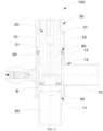
FIG. 1 is a schematic diagram of a stop valve of one or more embodiments. -
FIG. 2 is a cross-sectional schematic view of a stop valve of one or more embodiments. -
FIG. 3 is a partial enlarged view of portion A inFIG. 2 . -
FIG. 4 is a cross-sectional schematic view of a stop valve in a closed state in one or more embodiments. -
FIG. 5 is a partial enlarged view of portion B inFIG. 4 . -
FIG. 6 is a cross-sectional schematic view of a stop valve in a opened state in one or more embodiments. -
FIG. 7 is a schematic diagram of a stop valve of one or more embodiments. -
FIG. 8 is a cross-sectional schematic view of a stop valve of one or more embodiments. -
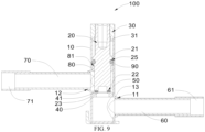
FIG. 9 is a cross-sectional schematic view of a stop valve of one or more embodiments. - Reference signs are as follows: 100 represents a stop valve; 10 represents a valve body; 11 represents a first opening; 12 represents a second opening; 13 represents a flanged hole; 20 represents a valve core; 21 represents a first conical portion; 22 represents a first groove; 23 represents a limiting portion; 24 represents a second conical portion; 25 represents a second groove; 30 represents a connecting block; 31 represents a seal portion; 40 represents a valve seat; 41 represents a protrusion portion; 50 represents a first sealing component; 60 represents a first connecting pipe; 61 represents a first transitional connecting pipe; 70 represents a second connecting pipe; 71 represents a second transitional connecting pipe; 80 represents a guiding block; 81 represents a guiding bevel; and 90 represents a second sealing component.
- The following will provide a clear and complete description of the technical solution in the embodiments of the present application, in communication with the accompanying drawings. Obviously, the described embodiments are only a part of the embodiments of the present application, not all of them. Based on the embodiments in the present application, all other embodiments obtained by ordinary skill in this art without creative labor fall within the scope of protection of the present application.
- Referring to
FIGs. 1 and7 , the present application provides astop valve 100 mounted in an air conditioning system. In the air conditioning system, thestop valve 100 plays an important role in cutting off and throttling a medium in a pipeline of the air conditioning system. - In related technology, the stop valve includes a valve body, a valve core and a connecting block. The valve body is sleeved on the connecting block and fixedly connected to the connecting block. The valve core is in threaded fit with the connecting block to realize the valve core moving in the valve body, thereby opening or closing the stop valve. However, the valve body is sleeved on the connecting block, which may result in an increase size of the valve body, leading to more material required for processing and a high cost of the stop valve.
- In order to solve above problems, referring to
FIGs. 2 to 9 , thestop valve 100 provided in the present application includes avalve body 10, avalve core 20 and a connectingblock 30. Thevalve body 10 is provided with afirst opening 11 and asecond opening 12. At least part of thevalve core 20 is located in thevalve body 10, and thevalve core 20 is movable in thevalve body 10 to communicate thefirst opening 11 with thesecond opening 12 or cut off a communication between thefirst opening 11 and thesecond opening 12. One end of the connectingblock 30 is located outside thevalve body 10, and the other end of the connectingblock 30 is fixedly connected to thevalve body 10. A part of thevalve core 20 extends into and is in threaded fit with the connectingblock 30. - Comparing with the
stop valve 100 in the present application, when an area of a cross section of the connectingblock 30 is unchanged, the valve body in the related technology is sleeved on the connecting block, which may result in an increase size of the valve body and more material required for processing. In the present application, thevalve body 10 is processed by pipes or rods. A side surface of thevalve body 10 is provided with aflanged hole 13. Theflanged hole 13 is connected to a connecting pipe. One end of the connectingblock 30 is located outside thevalve body 10, and the other end of the connectingblock 30 is fixedly connected to thevalve body 10, thereby reducing a diameter of thevalve body 10, a material consumption of thevalve body 10, and a cost of thestop valve 100. In addition, thread strength between the connectingblock 30 and thevalve core 20 can be improved, thereby improving stability of theoverall stop valve 100. - Referring to
FIGs. 2 ,4 ,6 ,8 and9 ,the connectingblock 30 towards thevalve body 10 extends towards thevalve body 10 to define aseal portion 31 along an axis of thevalve core 20. A side surface of theseal portion 31 towards thevalve body 10 is fixedly connected to an inner sidewall of thevalve body 10. A side surface of theseal portion 31 away from thevalve body 10 is separated from thevalve body 20. Theseal portion 31 abuts against the inner sidewall of thevalve body 10, which can improve a contact area between theseal portion 31 and the inner sidewall of thevalve body 10, thereby improving connecting strength between theseal portion 31 and thevalve body 10. Therefore, connecting strength between the connectingblock 30 and thevalve body 10 is improved, and stability of the connectingblock 30 is improved. - When the
stop valve 100 is located in a fully opened state, thevalve core 20 can abut against theseal portion 31 to define a linear seal. A periphery of thevalve core 20 protrudes towards the inner wall of thevalve body 10 to define a firstconical portion 21. A conical portion of the firstconical portion 21 can abut against theseal portion 31 and form the linear seal therewith, thereby improving reverse sealing performance between the connectingblock 30 and thevalve 20 and preventing the medium of the pipeline from leaking. Therefore, no additional sealing structure is required, a cost of the material is reduced, and difficulty of processing and assembling thestop valve 100 is lowered. - The
seal portion 31 can play a role in restricting thevalve core 20, thereby limiting a maximum valve opening of thestop valve 100. During an operation process of thestop valve 100, when thevalve core 20 moves towards the connectingblock 30 along the axis of thevalve core 20 until thevalve core 20 abuts against theseal portion 31, thestop valve 100 can reach to a state of the maximum valve opening. - The
stop valve 100 further includes avalve seat 40, a first connectingpipe 60, and a second connectingpipe 70. Thevalve seat 40 is disposed in thevalve body 10, located between thefirst opening 11 and thesecond opening 12, and connected to thevalve body 10. The first connectingpipe 60 is fixedly connected to thefirst opening 11. The second connectingpipe 70 is fixedly connected to thesecond opening 12. The first connectingpipe 60 is inserted into thefirst opening 11. Thefirst opening 11 is in communication with the air conditioning pipeline through the first connectingpipe 60. The second connectingpipe 70 is inserted into thesecond opening 12. Thesecond opening 12 is in communication with the air conditioning pipeline through the second connectingpipe 70. Thevalve seat 40 can play a role in restricting thevalve core 20 to move away from the connectingblock 30. When thestop valve 100 is in a closed state, thevalve core 20 abuts against thevalve seat 40 and cooperates with thevalve seat 40 to realize a seal, thereby cutting off the communication between thefirst opening 11 and thesecond opening 12. When thestop valve 100 is in an opened state, thevalve core 20 does not abut against thevalve seat 40, such that the medium is capable of being in communication between thefirst opening 11 andsecond opening 12. - Furthermore, the
stop valve 100 further includes a guidingblock 80. The guiding block is located in and connected to thevalve body 10. The guidingblock 80 is disposed towards thefirst opening 11 and thesecond opening 12 relative to the connectingblock 30. The guidingblock 80 is located on a periphery of a part of thevalve core 20, and thevalve core 20 can move along a guiding direction of the guidingblock 80 to communicate thefirst opening 11 with thesecond opening 12 or cut off the communication between thefirst opening 11 and thesecond opening 12. - Comparing a stop valve in the related technology with the
stop valve 100 in the present application, a connecting block in the related technology is disclosed in a valve body and threadedly connected to a valve core; the valve core moves along an axis of the valve core in a valve body only by a connecting block, However, by such arrangement, an axis of the valve core may be deviated from an axis of the valve body during a process of assembling or operating the valve core, such that the valve core can not greatly abut against the valve seat, leading to a leakage of a medium leaksand reducing a sealing performance of the stop valve. - In the present application, the
valve core 20 can move along the guiding direction of the guidingblock 80 by providing the guidingblock 80 in thevalve body 10. The guidingblock 80 cooperates with the connectingblock 30, thereby further reducing probability of deviation of thevalve core 20, and ensuring axes of the valve core, the valve body and the valve seat to coincide with each other. When thevalve core 20 moves along the axis of thevalve core 20 in thevalve body 10 and moves towards thevalve seat 40 to a limited position, thevalve core 20 can accurately abut against thevalve seat 40, and thevalve core 20 cooperateswith thevalve seat 40 to realize an sealing effect, thereby improving the sealing performance of thestop valve 100. It means that the guidingblock 80 prevents thevalve core 20 from deviating in thevalve body 10, thereby improving sealing reliability of thestop valve 100 after thevalve core 20 cooperates with thevalve seat 40. - In the present application, the guiding direction of the guiding
block 80 is an axis direction of the guidingblock 80. - Referring to
FIG. 2 , thesecond opening 12 is located on a periphery of thevalve body 10, a projection of the guidingblock 80 which is located on thevalve body 10 along a radial direction of thevalve body 10 does not overlap with thesecond opening 12. Therefore, it can prevent the guidingblock 80 from hindering the medium which flows from thesecond opening 12 to an inner part of thevalve body 10. Alternatively, the phenomenon that the guidingblock 80 hinders the medium which flows from the inner part of thevalve body 10 to thesecond opening 12 can be prevented. In addition, by such arrangement, noisy can be avoided in thevalve body 10, such that the medium can smoothly flow, thereby improving a use performance of thestop valve 100. - Furthermore, referring to
FIGs. 2 and3 , the guidingblock 80 includes a guidingbevel 81. The guidingbevel 81 is disposed on an end of the guidingblock 80 towards the connectingblock 30. The guidingbevel 81 is located on a side of the guidingblock 80 towards the axis of thevalve core 20. The guidingbevel 81 can play a enhancing role in guiding, facilitating guiding thevalve core 20 to insert into the guidingblock 80, preventing thevalve core 20 and the guidingblock 80 from bumping, and preventing thevalve core 20 from being unable to insert into the the guidingblock 80. Therefore, assembling efficiency of thevalve core 20 is improved. Alternatively, in other embodiments, the guidingblock 80 can be provided with other structures for playing a guiding role, except the guidingbevel 81. - Referring to
FIGs. 1 and2 , thefirst opening 11 is disposed on an end of thevalve body 10 away from the connectingblock 30. Thesecond opening 12 is disposed on the periphery of thevalve body 10. An angle is defined between an axis of thefirst opening 11 and an axis of thesecond opening 12. For example, the angle between the axis of thefirst opening 11 and the axis of thesecond opening 12 can include 75°, 90°, 120° and so on. Thevalve body 10 is a pipe-shaped hollow structure. The side periphery of thevalve body 10 is provided with at least oneflanged hole 13. Thesecond opening 12 is defined by the at least oneflanged hole 13. An angle is defined between the first connectingpipe 60 and the second connectingpipe 70. Thefirst opening 11 and thesecond opening 12 are regarded as an inlet or an outlet of the medium, respectively, such that the medium flows in thestop valve 100. - At least part of the
valve seat 40 is provided in thevalve body 10 through thefirst opening 11. The first connectingpipe 60 is inserted into and fixedly connected to thevalve seat 40. The periphery of thevalve body 10 is provided with the at least oneflanged hole 13. Flanging of the at least oneflanged hole 13 can increase a connecting area between thevalve body 10 and the second connectingpipe 70, facilitating connecting thevalve body 10 with the second connectingpipe 70, and improving connecting strength between thevalve body 10 and the second connectingpipe 70. When thestop valve 100 is in the opened state, the medium enters thevalve body 10 through thefirst opening 11, and flows outside thevalve body 10 through thesecond opening 12. Alternatively, the medium enters thevalve body 10 through thesecond opening 12, and flows outside thevalve body 10 through thefirst opening 11. - Referring to
FIG. 2 , when thestop valve 100 is in the closed state, one end of thevalve core 20 is connected to the connectingblock 30, the other end of thevalve core 20 abuts against thevalve seat 40 and cooperates with thevalve seat 40 in a hard-seal manner. Thevalve core 20 can be prevented from deviating by being in threaded fit with the connectingblock 30 and a guiding of the guidingblock 80, such that thevalve core 20 can move in thevalve body 10 along the axis of thevalve body 10. When thevalve core 20 moves towards thevalve seat 40 to the limited position, an end of thevalve core 20 abuts against thevalve seat 40 and cooperates with thevalve seat 40 to realize the sealing, thereby improving the sealing performance of thestop valve 100. - A second
conical portion 24 is defined by an end of thevalve core 20 towards thevalve seat 40. A part of the secondconical portion 24 is located in thevalve seat 40. A conical surface of the secondconical portion 24 can abut against thevalve seat 40 and form a linear seal therewith. Thevalve core 20 is in threaded fit with the connectingblock 30 to realize thevalve core 20 moving in thevalve body 10 along the axis of thevalve body 10. When the secondconical portion 24 of thevalve core 20 abuts against thevalve body 40, the conical surface of the secondconical portion 24 forms the linear seal with thevalve seat 40. A circular intersection line defined by an end of thevalve seat 40 towards thevalve core 20 intersecting with an inner sidewall of thevalve seat 40 abuts against the conical surface of the secondconical portion 24 to form a linear contact. The second conical portion is in tight fit with thevalve seat 40 to cut off the communication between thefirst opening 11 and thesecond opening 12. In one hand, thevalve core 20 is restricted, and in the other hand, the linear contact realizes a hard seal between thevalve core 20 and thevalve body 10, thereby improving a sealing performance between thevalve core 20 and thevalve body 10. In addition, the conical surface of the secondconical portion 24 is processed simply, which can save an amount of materials of thestop valve 100, thereby improving efficiency of processing and assembling thestop valve 100, and reducing a cost of thestop valve 100. - A structure of a
stop valve 100 in the present embodiment is substantially the same as that of thestop valve 100 in the first embodiment, similarities thereof will not be repeated, and differences thereof are as follows: referring toFIG. 4 , when thestop valve 100 is in the closed state, one end of avalve core 20 is connected to the connectingblock 30, and the other end of thevalve core 20 abuts against thevalve seat 40 and cooperates with thevalve seat 40 to define a soft seal. Thevalve core 20 can be prevented from deviating by being in threaded fit with the connectingblock 30 and a guiding of the guidingblock 80, such that thevalve core 20 can move along the axis of thevalve body 10 in thevalve body 10. When thevalve core 20 moves towards thevalve seat 40 to its limit, an end of thevalve core 20 abuts against thevalve seat 40 and cooperates with the valve seat to realize a seal, and the communication between thefirst opening 11 and thesecond opening 12 is cut off. - Referring to
FIGs. 4 and5 , thestop valve 100 further includes afirst sealing component 50. An end of thevalve core 20 away from the connectingblock 30 is provided with afirst groove 22. Thefirst sealing component 50 is disposed in thefirst groove 22. A surface of thevalve seat 40 towards thevalve core 20 is provided with aprotrusion portion 41. Theprotrusion portion 41 protrudes from thevalve seat 40. Thefirst sealing component 50 can abut against theprotrusion portion 41 and form the soft seal therewith. - The
first sealing component 50 can be in interference fit with thefirst groove 22. Thefirst sealing component 50 and thefirst groove 22 can support for each other by a compressive force generated by deformation of thefirst seal 50, such that the first sealing component is fixedly restricted in thefirst groove 22 to prevent thefirst sealing component 50 from detaching from thefirst groove 22 and reducing a sealing performance of thestop valve 100. Theprotrusion portion 41 can be inserted into and in tight fit with thefirst sealing component 50, thereby further improving the sealing performance of thestop valve 100 in the closed state. - A material of the
first sealing component 50 is rubber having softness. Therefore, thefirst sealing component 50 can be easily embedded to thefirst groove 22. In addition, thefirst sealing component 50 can abut against thevalve seat 40, such that thefirst sealing component 50 deforms, thereby improving a sealing performance of thefirst sealing component 50, and further improving the sealing performance of thestop valve 100. Alternatively, in other embodiments, the material of thefirst sealing component 50 can be other materials which can form the soft seal with thevalve seat 40, which is not limited herein. - Furthermore, a limiting
portion 23 is defined by an end of thevalve core 20 towards thevalve seat 40. The limitingportion 23 can restrict thefirst sealing component 50 to prevent the first sealing component from detaching from thefirst groove 22 and reducing the sealing performance of thestop valve 100. In the present embodiment, an end of a side wall of the thefirst groove 22 towards the axis of thevalve core 20 extends away from the connectingblock 30 and bends to form the limitingportion 23. The limitingportion 23 is in an expended-mouth shape. In other embodiments, the limitingportion 23 can be in a circular frustum shape, as long as the phenomenon that the first sealing component detaches from thefirst groove 22 can be prevented. - Referring to
FIGs. 7 and 8 , thefirst opening 11 and thesecond opening 12 are both provided around the periphery of thevalve body 10, and an axis of thefirst opening 11 and an axis of thesecond opening 12 are separated with a distance. Thefirst opening 11 and thesecond opening 12 are both provided around the periphery of thevalve body 10, and the axis of thefirst opening 11 is parallel to the axis of thesecond opening 12. - The
valve body 10 is a pipe-shaped hollow structure. The periphery of thevalve body 10 is provided with at least twoflanged holes 13. Thefirst opening 11 and thesecond opening 12 are defined by the at least twoflanged holes 13, respectively. The axis of thefirst opening 11 and the axis of thesecond opening 12 are separated with the distance. Thefirst opening 11 and thesecond opening 12 are disposed on different sides of the periphery of thevalve body 10, respectively. In an embodiment, the axis of thefirst opening 11 is parallel to the axis of thesecond opening 12. Thefirst opening 11 and thesecond opening 12 are regarded as an inlet or an outlet of the medium, respectively, such that the medium flows in thestop valve 100. - The periphery of the
valve body 10 is provided with the at least twoflanged holes 13. Flanging of theflanged hole 13 can increase a connecting area between the first connectingpipe 60 and the second connectingpipe 70, facilitating connecting thevalve body 10 with the first connectingpipe 60 and the second connectingpipe 70, thereby improving connecting strength among thevalve body 10, the first connectingpipe 60 and the second connectingpipe 70. When thestop valve 100 is in the opened state, the medium enters thevalve body 10 through thefirst opening 11 and flows outside thesecond opening 12. Alternatively, the medium enters the valve body through thesecond opening 12 and flows outside thefirst opening 11. - Referring to
FIG. 8 , when astop valve 100 is in the closed state, one end of thevalve core 20 is connected to the connectingblock 30, the other end of thevalve core 20 abuts against thevalve seat 40 and cooperates with thevalve seat 40 in a hard-seal manner. Thevalve core 20 can prevent from deviating by being in threaded fit with the connectingblock 30 and a guiding of the guidingblock 80, such that thevalve core 20 can move in thevalve body 10 along the axis of thevalve body 10. When thevalve core 20 moves towards thevalve seat 40 to its limit, an end of thevalve core 20 abuts against thevalve seat 40 and cooperates with thevalve seat 40 to realize a seal, thereby improving the sealing performance of thestop valve 100. - A second
conical portion 24 is defined by an end of thevalve core 20 towards thevalve seat 40. A part of the secondconical portion 24 is located in thevalve seat 40. The conical surface of the secondconical portion 24 can abut against thevalve seat 40 to form the linear seal. Thevalve core 20 can move in thevalve body 10 along the axis of thevalve body 10 by being in thread fit with the connectingblock 30. When the secondconical portion 24 of thevalve core 20 abuts against thevalve body 40, a conical surface of the secondconical portion 24 is in linear contact with thevalve seat 40. A circular intersection line defined by an end of thevalve seat 40 towards thevalve core 20 intersecting a side wall of thevalve seat 40 abuts against the conical surface of the secondconical portion 24 to form the linear contact. The secondconical portion 24 is in tight fit with thevalve seat 40 to cut off the communication between thefirst opening 11 and thesecond opening 12. In one hand, thevalve core 20 is restricted And in the other hand, the linear contact realizes a hard seal between thevalve core 20 and thevalve body 10, thereby improving a sealing performance between thevalve core 20 and thevalve body 10. Furthermore, the conical surface of the secondconical portion 24 is processed simply, which can save an amount of a material of thestop valve 100, thereby improving a processing and assembling efficiency of thestop valve 100, and reducing a cost of thestop valve 100. - A structure of a
stop valve 100 in the present embodiment is substantially the same as that of thestop valve 100 in the third embodiment, similarities thereof will not be repeated, and difference thereof is as follows: referring toFIG. 9 , when thestop valve 100 is in the closed state, one end of thevalve core 20 is connected to the connectingblock 30, and the other end of thevalve core 20 abuts against thevalve seat 40 and cooperates with thevalve seat 40 in the soft seal manner. Thevalve core 20 can prevent from deviating by being in threaded fit with the connectingblock 30 and a guiding of a guidingblock 80, such that thevalve core 20 can move along the axis of thevalve body 10 in thevalve body 10. When thevalve core 20 moves towards thevalve seat 40 to its limit, an end of thevalve core 20 abuts against thevalve seat 40 and cooperates with thevalve seat 40 to realize a seal, and the communication between thefirst opening 11 and thesecond opening 12 is cut off. - The
stop valve 100 further includes afirst sealing component 50. An end of thevalve core 20 away from the connectingblock 30 is provided with afirst groove 22. Thefirst sealing component 50 is disposed in thefirst groove 22. An end of thevalve seat 40 towards thevalve core 20 is provided with aprotrusion portion 41. Theprotrusion portion 41 protrudes from thevalve seat 40. Thefirst sealing component 50 can abut against theprotrusion portion 41 and form a soft seal therewith. - The
first sealing component 20 can be in interference fit with thefirst groove 22. Thefirst sealing component 50 and thefirst groove 22 can support for each other by a compressive force generated by deformation of thefirst seal 50, such that thefirst sealing component 50 is fixedly restricted in thefirst groove 22 to prevent the first sealing component from detaching from thefirst groove 22 and reducing the sealing performance of thestop valve 100. Theprotrusion portion 41 can be inserted into and in tight fit with thefirst sealing component 50, thereby further improving the sealing performance of thestop valve 100 in the closed state. - A material of the
first sealing component 50 is rubber having softness. Therefore, thefirst sealing component 50 can be easily embedded to thefirst groove 22. In addition, thefirst sealing component 50 can abut against thevalve seat 40, such that thefirst sealing component 50 deforms, thereby improving a sealing performance of thefirst sealing component 50, and further improving the sealing performance of thestop valve 100. Alternatively, in other embodiments, the material of thefirst sealing component 50 can be other materials which can form the soft seal with thevalve seat 40, which is not limited herein. - Furthermore, a limiting
portion 23 is defined by an end of thevalve core 20. The limitingportion 23 can restrict thefirst sealing component 50 to prevent thefirst sealing component 50 from detaching from thefirst groove 22 and lowering the sealing performance of thestop valve 100. In the present embodiment, an end of a side wall of the thefirst groove 22 towards an axis of thevalve core 20 extends away from the connectingblock 30 and bends to form the limitingportion 23. The limiting portion is in an expended-mouth shape. In other embodiments, the limitingportion 23 can be in a circular frustum shape, as long as the limitingportion 23 can play a role in preventing thefirst sealing component 50 from detaching from thefirst groove 22. - Referring to
FIGs. 2 to 9 , thestop valve 100 further includes asecond sealing component 90. Thevalve core 20 is provided with asecond groove 25 between the connectingblock 30 and the guidingblock 80. Thesecond sealing component 90 is disposed in thesecond sealing component 25 to prevent liquid from leaking. - The
second sealing component 90 is a circumferential sealing component, i.e., thesecond sealing component 90 is a sealing ring encircling the periphery of thevalve core 20, and thesecond groove 25 is correspondingly provided as a ring-shaped groove. Therefore, when thesecond sealing component 90 is disposed in thesecond groove 25, thesecond sealing component 90 can ensure sealing reliably between thevalve core 20 and thevalve body 10. - Referring to
FIG. 7 , thestop valve 100 further includes a first transitional connectingpipe 61 and a second transitional connectingpipe 71. The first transitional connectingpipe 61 is sleeved on the first connectingpipe 60. The second transitional connectingpipe 71 is sleeved on the second transitional connectingpipe 70. A material of the first transitional connectingpipe 61 is different from a material of the first connectingpipe 60. A material of the second transitional connectingpipe 71 is different from a material of the second connecting pipe. The first connecting pipe and the second connecting pipe are both made of stainless steel. The first transitional connectingpipe 61 and the second transitional connectingpipe 71 are both made of copper. Therefore, it is conducive to being welding to external pipelines, thereby improving efficiency for mounting thestop valve 100. - The various technical features of the above embodiments can be combined in any way. In order to make the description concise, not all possible combinations of the various technical features in the above embodiments have been described. However, as long as there is no contradiction in the combination of these technical features, they should be considered within the scope of the specification.
- The above embodiments only express several embodiments of the present application, and their descriptions are more specific and detailed, but should not be understood as limiting the scope of the disclosure. It should be pointed out that for ordinary skill in the art, several modifications and improvements can be made without departing from the concept of the disclosure, which are within the scope of protection of the disclosure. Therefore, the scope of protection of the present application should be based on the attached claims.
Claims (12)
- A stop valve characterized by comprising:a valve body provided with a first opening and a second opening;a valve core, wherein at least part of the valve core is located in the valve body, the valve core is movable in the valve body to communicate the first opening with the second opening and cut off a communication between the first opening and the second opening; anda connecting block, wherein one end of the connecting block is located outside the valve body, the other end of the connecting block is fixedly connected to an end of the valve body, a part of the valve core extends into the connecting block and is in threaded fit with the connecting block;wherein the connecting block extends towards the valve body to define a seal portion along an axis of the valve core, and when the stop valve is in a fully opened state, the valve core is capable of abutting against the seal portion and forming a linear seal therewith.
- The stop valve of claim 1, wherein a side surface of the seal portion towards the valve body is fixedly connected to an inner sidewall of the valve body, and a side surface of the seal portion away from the valve body is separate from the valve core.
- The stop valve of claim 1, wherein a periphery of the valve core protrudes from the inner sidewall of the valve body to define a first conical portion, and a conical surface of the first conical portion is capable of abutting against the seal portion and forming a linear seal therewith.
- The stop valve of claim 1, further comprising a guiding block located in and connected to the valve body, wherein the guiding block is arranged towards the first opening and the second opening relative to the connecting block, the guiding block is located on a periphery of a part of the valve core, and the valve core is capable of moving along a guiding direction of the guiding block to communicate the first opening with the second opening or cut off the communication between the first opening and the second opening.
- The stop valve of claim 4, wherein the second opening is located on a periphery of the valve body, and a projection of the guiding block which is located on the valve body along a radial direction of the valve body does not overlap with the second opening.
- The stop valve of claim 4, wherein the guiding block comprises a guiding bevel and the guiding bevel is disposed on an end of the guiding block towards the connecting block.
- The stop valve of claim 1, further comprising a valve seat disposed in the valve body, wherein the valve seat is located between the first opening and the second opening and connected to the valve body; and when the stop valve is in a closed state, one end of the valve core is connected to the connecting block, and the other end of the valve core abuts against the valve seat and cooperates with the valve seat in a hard-seal manner or a soft-seal manner.
- The stop valve of claim 7, wherein a second conical portion is defined by an end of the valve core towards the valve seat, a part of the second conical portion is located in the valve seat, and a conical surface of the second conical portion is capable of abutting against the valve seat and form the linear seal therewith.
- The stop valve of claim 7, further comprising a first sealing component, wherein an end of the valve core away from the connecting block is provided with a first groove, the first sealing component is disposed in the first groove; and an end surface of the valve seat towards the valve core is provided with a protrusion portion, the protrusion portion protrudes from the valve seat, and the first sealing component abuts against the protrusion portion and form a soft seal.
- The stop valve of claim 7, wherein the first opening is disposed on an end of the valve body away from the connecting block, the second opening is disposed on a periphery of the valve body, an angle is defined between an axis of the first opening and an axis of the second opening; or the first opening and the second opening are both disposed on the periphery of the valve body, the axis of the first opening is parallel to the axis of the second opening, and the first opening and the second opening are disposed on different sides of the periphery of the valve body, respectively.
- The stop valve of claim 10, further comprising a first connecting pipe and a second connecting pipe, wherein the first connecting pipe is fixedly connected to the first opening, and the second connecting pipe is fixedly connected to the second opening.
- The stop valve of claim 11, further comprising a first transitional connecting pipe and a second transitional connecting pipe, wherein the first transitional connecting pipe is sleeved on the first connecting pipe, the second transitional connecting pipe is sleeved on the second connecting pipe, a material of the first transitional connecting pipe is different from a material of the first connecting pipe, and a material of the second transitional connecting pipe is different from a material of the second connecting pipe.
Applications Claiming Priority (3)
| Application Number | Priority Date | Filing Date | Title |
|---|---|---|---|
| CN202221673247.6U CN217977421U (en) | 2022-06-30 | 2022-06-30 | Shut-off valve |
| CN202221674476.XU CN217977422U (en) | 2022-06-30 | 2022-06-30 | Shut-off valve |
| PCT/CN2023/101648 WO2024001898A1 (en) | 2022-06-30 | 2023-06-21 | Stop valve |
Publications (2)
| Publication Number | Publication Date |
|---|---|
| EP4549784A1 true EP4549784A1 (en) | 2025-05-07 |
| EP4549784A4 EP4549784A4 (en) | 2025-10-22 |
Family
ID=89383255
Family Applications (1)
| Application Number | Title | Priority Date | Filing Date |
|---|---|---|---|
| EP23830077.6A Pending EP4549784A4 (en) | 2022-06-30 | 2023-06-21 | Shut-off valve |
Country Status (5)
| Country | Link |
|---|---|
| US (1) | US20250109799A1 (en) |
| EP (1) | EP4549784A4 (en) |
| JP (1) | JP2025515270A (en) |
| KR (1) | KR20250003841A (en) |
| WO (1) | WO2024001898A1 (en) |
Families Citing this family (1)
| Publication number | Priority date | Publication date | Assignee | Title |
|---|---|---|---|---|
| CN120969510A (en) * | 2025-10-20 | 2025-11-18 | 江苏福达电器有限公司 | Air conditioner stop valve based on asymmetric spherical sealing valve core |
Family Cites Families (17)
| Publication number | Priority date | Publication date | Assignee | Title |
|---|---|---|---|---|
| US5711508A (en) * | 1995-06-07 | 1998-01-27 | Itt Automotive, Inc. | Quick connect fluid coupling equipped with check valve and service valve |
| JP3259950B2 (en) * | 1997-03-31 | 2002-02-25 | 千代田空調機器株式会社 | Valve device |
| CN203627813U (en) * | 2013-10-14 | 2014-06-04 | 浙江盾安禾田金属有限公司 | Stop valve for air conditioner |
| JP6816957B2 (en) * | 2015-05-28 | 2021-01-20 | ナブテスコ株式会社 | Valve device |
| CN106321916B (en) * | 2016-11-08 | 2018-07-20 | 玉环江林水暖管业有限公司 | A kind of flow safety valve |
| EP3480435B1 (en) * | 2017-11-07 | 2022-03-02 | Volvo Car Corporation | Valve device for a rankine system |
| CN111577902A (en) * | 2019-02-18 | 2020-08-25 | 浙江盾安禾田金属有限公司 | Valve body assembly |
| JP7333045B2 (en) * | 2019-02-20 | 2023-08-24 | 株式会社不二工機 | flow control valve |
| CN213332385U (en) * | 2020-07-10 | 2021-06-01 | 浙江盾安禾田金属有限公司 | Stop valve |
| CN215059501U (en) * | 2021-04-22 | 2021-12-07 | 浙江三花智能控制股份有限公司 | a valve device |
| CN216742842U (en) * | 2021-11-23 | 2022-06-14 | 浙江盾安人工环境股份有限公司 | Stop valve |
| CN216742876U (en) * | 2021-12-18 | 2022-06-14 | 浙江盾安人工环境股份有限公司 | Stop valve and refrigerating system thereof |
| CN216742874U (en) * | 2021-12-18 | 2022-06-14 | 浙江盾安人工环境股份有限公司 | Stop valve and refrigerating system thereof |
| CN216742875U (en) * | 2021-12-18 | 2022-06-14 | 浙江盾安人工环境股份有限公司 | Stop valve and refrigerating system thereof |
| CN216742879U (en) * | 2022-01-27 | 2022-06-14 | 浙江盾安人工环境股份有限公司 | Stop valve and refrigerating system thereof |
| CN217977421U (en) * | 2022-06-30 | 2022-12-06 | 浙江盾安人工环境股份有限公司 | Shut-off valve |
| CN217977422U (en) * | 2022-06-30 | 2022-12-06 | 浙江盾安人工环境股份有限公司 | Shut-off valve |
-
2023
- 2023-06-21 EP EP23830077.6A patent/EP4549784A4/en active Pending
- 2023-06-21 JP JP2024560275A patent/JP2025515270A/en active Pending
- 2023-06-21 KR KR1020247038000A patent/KR20250003841A/en active Pending
- 2023-06-21 WO PCT/CN2023/101648 patent/WO2024001898A1/en not_active Ceased
-
2024
- 2024-12-13 US US18/979,695 patent/US20250109799A1/en active Pending
Also Published As
| Publication number | Publication date |
|---|---|
| JP2025515270A (en) | 2025-05-14 |
| KR20250003841A (en) | 2025-01-07 |
| EP4549784A4 (en) | 2025-10-22 |
| US20250109799A1 (en) | 2025-04-03 |
| WO2024001898A1 (en) | 2024-01-04 |
Similar Documents
| Publication | Publication Date | Title |
|---|---|---|
| EP3604883B1 (en) | Resinous pipe joint | |
| AU2013381822B2 (en) | Fluid flow control devices and systems, and methods of flowing fluids therethrough | |
| US20250109799A1 (en) | Stop valve | |
| EP4471304A1 (en) | Stop valve and refrigeration system having same | |
| EP4450851A1 (en) | Stop valve | |
| CN218267295U (en) | Electronic expansion valve | |
| KR20130040852A (en) | Valve element of butterfly valve | |
| US11519516B2 (en) | Control valve | |
| CN217977421U (en) | Shut-off valve | |
| CN110360344B (en) | Rotary reversing valve | |
| CN223242153U (en) | One-way valve | |
| CN217977422U (en) | Shut-off valve | |
| CN220286528U (en) | a one-way valve | |
| CN219994547U (en) | Novel valve pocket type blow-down valve for natural gas station | |
| CN216742874U (en) | Stop valve and refrigerating system thereof | |
| CN210240623U (en) | Reduce cock structure of plug valve moment of torsion | |
| CN223004491U (en) | One-way valve, heating and ventilation equipment outdoor unit and heating and ventilation equipment | |
| CN215950490U (en) | Anti-deposition check valve | |
| KR20240025015A (en) | Three-way pipe and air conditioning system using the three-way pipe | |
| CN222067657U (en) | Micro-arc oxidation insulating fixed ball valve seat | |
| CN221880373U (en) | Valve body of valve component and valve | |
| CN223360000U (en) | One-way valve and valve group device | |
| CN223004492U (en) | One-way valve, heating and ventilation equipment outdoor unit and heating and ventilation equipment | |
| CN223004493U (en) | Check valve, HVAC equipment outdoor unit and HVAC equipment | |
| US20240410470A1 (en) | Valve Head Structure and Flow Regulating Valve with Valve Head Structure |
Legal Events
| Date | Code | Title | Description |
|---|---|---|---|
| STAA | Information on the status of an ep patent application or granted ep patent |
Free format text: STATUS: THE INTERNATIONAL PUBLICATION HAS BEEN MADE |
|
| PUAI | Public reference made under article 153(3) epc to a published international application that has entered the european phase |
Free format text: ORIGINAL CODE: 0009012 |
|
| STAA | Information on the status of an ep patent application or granted ep patent |
Free format text: STATUS: REQUEST FOR EXAMINATION WAS MADE |
|
| 17P | Request for examination filed |
Effective date: 20241210 |
|
| AK | Designated contracting states |
Kind code of ref document: A1 Designated state(s): AL AT BE BG CH CY CZ DE DK EE ES FI FR GB GR HR HU IE IS IT LI LT LU LV MC ME MK MT NL NO PL PT RO RS SE SI SK SM TR |
|
| DAV | Request for validation of the european patent (deleted) | ||
| DAX | Request for extension of the european patent (deleted) | ||
| A4 | Supplementary search report drawn up and despatched |
Effective date: 20250924 |
|
| RIC1 | Information provided on ipc code assigned before grant |
Ipc: F16K 1/36 20060101AFI20250918BHEP Ipc: F16K 27/02 20060101ALI20250918BHEP Ipc: F16K 1/46 20060101ALI20250918BHEP |