EP4549766A1 - Shaft bearing retainer assembly - Google Patents
Shaft bearing retainer assembly Download PDFInfo
- Publication number
- EP4549766A1 EP4549766A1 EP24206532.4A EP24206532A EP4549766A1 EP 4549766 A1 EP4549766 A1 EP 4549766A1 EP 24206532 A EP24206532 A EP 24206532A EP 4549766 A1 EP4549766 A1 EP 4549766A1
- Authority
- EP
- European Patent Office
- Prior art keywords
- shaft
- retainer ring
- retainer
- bearing
- threaded
- Prior art date
- Legal status (The legal status is an assumption and is not a legal conclusion. Google has not performed a legal analysis and makes no representation as to the accuracy of the status listed.)
- Granted
Links
Images





Classifications
-
- F—MECHANICAL ENGINEERING; LIGHTING; HEATING; WEAPONS; BLASTING
- F16—ENGINEERING ELEMENTS AND UNITS; GENERAL MEASURES FOR PRODUCING AND MAINTAINING EFFECTIVE FUNCTIONING OF MACHINES OR INSTALLATIONS; THERMAL INSULATION IN GENERAL
- F16C—SHAFTS; FLEXIBLE SHAFTS; ELEMENTS OR CRANKSHAFT MECHANISMS; ROTARY BODIES OTHER THAN GEARING ELEMENTS; BEARINGS
- F16C35/00—Rigid support of bearing units; Housings, e.g. caps, covers
- F16C35/04—Rigid support of bearing units; Housings, e.g. caps, covers in the case of ball or roller bearings
- F16C35/06—Mounting or dismounting of ball or roller bearings; Fixing them onto shaft or in housing
- F16C35/063—Fixing them on the shaft
-
- F—MECHANICAL ENGINEERING; LIGHTING; HEATING; WEAPONS; BLASTING
- F16—ENGINEERING ELEMENTS AND UNITS; GENERAL MEASURES FOR PRODUCING AND MAINTAINING EFFECTIVE FUNCTIONING OF MACHINES OR INSTALLATIONS; THERMAL INSULATION IN GENERAL
- F16C—SHAFTS; FLEXIBLE SHAFTS; ELEMENTS OR CRANKSHAFT MECHANISMS; ROTARY BODIES OTHER THAN GEARING ELEMENTS; BEARINGS
- F16C19/00—Bearings with rolling contact, for exclusively rotary movement
- F16C19/22—Bearings with rolling contact, for exclusively rotary movement with bearing rollers essentially of the same size in one or more circular rows, e.g. needle bearings
- F16C19/24—Bearings with rolling contact, for exclusively rotary movement with bearing rollers essentially of the same size in one or more circular rows, e.g. needle bearings for radial load mainly
- F16C19/26—Bearings with rolling contact, for exclusively rotary movement with bearing rollers essentially of the same size in one or more circular rows, e.g. needle bearings for radial load mainly with a single row of rollers
-
- F—MECHANICAL ENGINEERING; LIGHTING; HEATING; WEAPONS; BLASTING
- F16—ENGINEERING ELEMENTS AND UNITS; GENERAL MEASURES FOR PRODUCING AND MAINTAINING EFFECTIVE FUNCTIONING OF MACHINES OR INSTALLATIONS; THERMAL INSULATION IN GENERAL
- F16C—SHAFTS; FLEXIBLE SHAFTS; ELEMENTS OR CRANKSHAFT MECHANISMS; ROTARY BODIES OTHER THAN GEARING ELEMENTS; BEARINGS
- F16C2226/00—Joining parts; Fastening; Assembling or mounting parts
- F16C2226/50—Positive connections
- F16C2226/60—Positive connections with threaded parts, e.g. bolt and nut connections
-
- F—MECHANICAL ENGINEERING; LIGHTING; HEATING; WEAPONS; BLASTING
- F16—ENGINEERING ELEMENTS AND UNITS; GENERAL MEASURES FOR PRODUCING AND MAINTAINING EFFECTIVE FUNCTIONING OF MACHINES OR INSTALLATIONS; THERMAL INSULATION IN GENERAL
- F16C—SHAFTS; FLEXIBLE SHAFTS; ELEMENTS OR CRANKSHAFT MECHANISMS; ROTARY BODIES OTHER THAN GEARING ELEMENTS; BEARINGS
- F16C2360/00—Engines or pumps
- F16C2360/23—Gas turbine engines
Definitions
- the invention relates to rotating shafts in general and to apparatus for securing bearings relative to a rotating shaft in particular.
- Turbomachines such as gas turbine engines, typically include fan, compressor, combustor, and turbine sections.
- the fan section drives air along a core flow path into the compressor section.
- the compressed air is mixed with fuel and combusted in the combustor section.
- the products of combustion are expanded in the turbine section.
- a typical turbine engine has two or three shafts (sometimes referred to as "spools") that transmit torque between the turbine and compressor sections of the engine. Each of these shafts is typically supported by bearings. In some applications, a shaft bearing may be configured to accommodate both axial and radial loads. In other applications, a shaft bearing may be configured to accommodate only an axial load. Turbine engines also often include a gearbox (e.g., and accessory gearbox) driven off of one of the engine shafts. An accessory gearbox may be used to drive an electric generator, a hydraulic pump, an oil pump, or any combination thereof.
- shaft bearings may undesirably "walk” from their original location. It is desirable to have a structure that prevents bearing movement, and in particular a structure that is easily manufactured and implemented, and one that is cost effective.
- a shaft bearing retainer assembly includes an axially extending shaft, a bearing, and a bearing retainer subassembly.
- the shaft has a first radial surface, a second radial surface, a distal end, a bearing seat, and a retainer cavity.
- the first radial surface is opposite the second radial surface.
- the bearing seat is engaged with the first radial surface and extends axially inward from the distal end.
- the retainer cavity is disposed in the second radial surface of the shaft and extends axially inward from the distal end.
- the shaft includes a first threaded surface portion disposed in the retainer cavity and a second threaded surface portion in the second radial surface.
- the bearing has a race and a plurality of roller elements.
- the bearing race is mounted in the bearing seat.
- the bearing retainer subassembly includes a first retainer ring and a second retainer ring.
- the first retainer ring is in threaded engagement with the first threaded surface portion and engaged with the bearing race.
- the second retainer ring is in threaded engagement with the second threaded surface portion and engaged with the first retainer ring.
- the threaded engagement between the first retainer ring and the first threaded surface portion is a first threaded engagement
- the threaded engagement between the second retainer ring and the second threaded surface portion is a second threaded engagement
- the first threaded engagement may be different than the second threaded engagement
- first threaded engagement has a first threads per inch value (first thread pitch value)
- second threaded engagement has a second threads per inch value (second thread pitch value)
- first threads per inch value first thread pitch value
- first thread pitch value second thread pitch value
- first threads per inch value first thread pitch value
- second thread pitch value second thread pitch value
- first threaded engagement may have a left-handed thread and the second threaded engagement may have a right-handed thread, or the first threaded engagement may have a right-handed thread and the second threaded engagement may have a left-handed thread.
- the first retainer ring may have a FRR axial member, a FRR radial member, and a FRR threaded collar, and the FRR threaded collar may be disposed adjacent a first axial end of the FRR axial member and the FRR radial member may extend radially out from the FRR axial member at a second axial end of the FRR axial member, and the FRR threaded collar may be in threaded engagement with the first threaded surface portion.
- the second retainer ring may have a SRR axial member, a SRR radial member, and a SRR threaded collar, and the SRR threaded collar may be disposed adjacent a first axial end of the SRR axial member and the SRR radial member may extend radially out from the SRR axial member at a second axial end of the SRR axial member, and the SRR threaded collar may be in threaded engagement with the second threaded surface portion.
- the bearing seat may include an axially extending bearing mount surface and a BS shoulder surface, and the axially extending bearing mount surface may extend from the distal end to the BS shoulder surface and the BS shoulder surface may extend between the bearing mount surface and the shaft outer radial surface.
- the bearing seat may be defined by a shoulder protrusion extending outwardly from the first radial surface and a portion of the radial surface extending between the shoulder protrusion and the shaft distal end.
- the retainer cavity may include an RC inner diameter surface and an RC shoulder surface, and the RC inner diameter surface may extend from the distal end to the RC shoulder surface and the RC shoulder surface may extend between the RC inner diameter surface and the shaft inner radial surface.
- the shaft bearing retainer assembly may include a locking mechanism configured to inhibit relative rotation between the first retainer ring and the second retainer ring.
- the locking mechanism may include at least one locking key engaged with the first retainer ring and the second retainer ring.
- the locking mechanism may include at least one lock post extending out from the first retainer ring and a slotted aperture disposed in the second retainer ring, and the lock post may include a stem and a head, and the slotted aperture may include a receiver portion and a slot portion, and the slotted aperture may include a stem locking feature.
- the locking mechanism may include at least one mechanical fastener engaged with the first retainer ring and the second retainer ring.
- the locking mechanism may include at least one biased detent member engaged between the first retainer ring and the second retainer ring.
- the locking mechanism may include a deformable feature attached to one of the first retainer ring or the second retainer ring, the deformable feature configured to engage with the other of the first retainer ring or the second retainer ring to inhibit relative rotation between the first retainer ring and the second retainer ring.
- the shaft first radial surface may be an outer radial surface of the shaft, and the shaft second radial surface may be an inner radial surface of the shaft, or the shaft first radial surface may be an inner radial surface of the shaft, and the shaft second radial surface may be an outer radial surface of the shaft.
- a bearing assembly for a rotating shaft having a first radial surface, a second radial surface, and a distal end.
- the first radial surface is opposite the second radial surface.
- the second radial surface has a first SRR portion disposed at a first diameter and a second SSR portion disposed at a second diameter.
- the first diameter is different than the second diameter.
- the bearing assembly includes a first threaded surface portion, a second threaded surface portion, a bearing, and a bearing retainer assembly.
- the first threaded surface portion is disposed on the first SRR portion of the second radial surface.
- the second threaded surface portion is disposed on the second SRR portion of the second radial surface.
- the bearing has a race and a plurality of roller elements.
- the bearing race is mounted on the first radial surface.
- the bearing retainer assembly includes a first retainer ring and a second retainer ring.
- the first retainer ring is in threaded engagement with the first SRR portion and engaged with the bearing race.
- the second retainer ring is in threaded engagement with the second SRR portion and engaged with the first retainer ring.
- the threaded engagement between the first retainer ring and the first threaded surface portion is a first threaded engagement
- the threaded engagement between the second retainer ring and the second threaded surface portion is a second threaded engagement.
- the first threaded engagement is different than the second threaded engagement.
- first threaded engagement has a first threads per inch value (first thread pitch value)
- second threaded engagement has a second threads per inch value (second thread pitch value)
- first threads per inch value first thread pitch value
- first thread pitch value second thread pitch value
- first threads per inch value first thread pitch value
- second thread pitch value second thread pitch value
- first threaded engagement may have a left-handed thread and the second threaded engagement may have a right-handed thread, or the first threaded engagement may have a right-handed thread and the second threaded engagement may have a left-handed thread.
- FIG. 1 shows a partially sectioned diagrammatic view of a geared gas turbine engine 20.
- the gas turbine engine 20 extends along an axial centerline 22 between an upstream air flow inlet 24 and a downstream air flow exhaust 26.
- the gas turbine engine 20 includes a fan section 28, a compressor section 30, a combustor section 32, a turbine section 34, and an accessory gearbox 33.
- the combustor section 32 includes a combustor 35.
- the compressor section 30 includes a low pressure compressor (LPC) 36 and a high pressure compressor (HPC) 38.
- the turbine section 34 includes a high pressure turbine (HPT) 40 and a low pressure turbine (LPT) 42.
- the engine sections are arranged sequentially along the centerline 22.
- the fan section 28 is connected to a geared architecture 44, for example, through a fan shaft 46.
- the geared architecture 44 and the LPC 36 are connected to and driven by the LPT 42 through a low speed shaft 48.
- the HPC 38 is connected to and driven by the HPT 40 through a high speed shaft 50.
- the accessory gearbox 33 may be driven off of the low speed shaft 48 or the high speed shaft 50; e.g., by a tower shaft. Accessory gearboxes often include internal shafts. The accessory gearbox 33 may be used to drive peripheral equipment such as an electric generator, a hydraulic pump, an oil pump, and the like or combinations thereof. The present disclosure is not limited to any particular accessory gearbox configuration.
- the aforesaid shafts 46, 48, 50 are supported by bearings 52.
- the terms "forward”, “leading”, “aft, “trailing” are used herein to indicate the relative position of a component or surface.
- a "leading edge" of a stator vane or rotor blade encounters core gas air before the "trailing edge” of the same.
- the fan section 28 is “forward” of the compressor section 30 and the turbine section 34 is “aft” of the compressor section 30.
- the terms “inner radial” and “outer radial” refer to relative radial positions from the engine centerline 22. An inner radial component or path is disposed radially closer to the engine centerline 22 than an outer radial component or path.
- the gas turbine engine 20 diagrammatically shown is an example provided to facilitate the description herein. The present disclosure is not limited to any particular gas turbine engine configuration.
- the various embodiments of the present disclosure shaft bearing assembly described herein may be used in a variety of different applications; e.g., within a turbine engine, within a gearbox, and the like.
- the present disclosure shaft bearing retainer assembly has particular utility in applications having limited space adjacent the distal end of a shaft to secure a bearing engaged with the shaft.
- Accessory gearboxes used with aircraft turbine engines are a specific example of an application that very often has limited space adjacent the distal end of a shaft. Consequently, the present disclosure is understood to have particular utility in accessory gearbox applications.
- the present disclosure is detailed herein in terms of a bearing 52 disposed radially outside of the shaft 54 and other components relative to a outer radial bearing 52.
- the present disclosure is not, however, limited to an outer bearing 52 construct.
- the bearing 52 includes an inner race 64, an outer race 66, and a plurality of roller elements 68 disposed between the inner and outer races 64, 66.
- the present disclosure is not limited to any particular bearing 52 configuration other than one having inner and outer races 64, 66 and roller elements 68.
- the roller elements 68 are shown as cylindrical but the present disclosure is not limited to any particular roller element 68 configuration; e.g., the roller elements 68 may be spherical tapered roller elements, and the like.
- the bearing 52 may be configured to accommodate axial loads, or radial loads, or any combination thereof.
- the bearing inner race 64 includes an inner diameter surface 70, a roller element surface 72, a first lateral surface 74, and a second lateral surface 76.
- the first and second lateral surfaces 74, 76 are opposite one another and extend between the inner diameter surface 70 and the roller element surface 72.
- the structural component 62 shown (in dashed lines) radially outside of the bearing 52 may be a static structure (e.g., stationary relative to the shaft 54) or a rotational structure (e.g., capable of rotation relative to the shaft 54).
- the structural component is disposed radially inside of the bearing 52.
- the structural component 62 is engaged with the bearing outer race 66.
- the present disclosure is not limited to any particular structural component 62 disposed radially outside of the bearing 52.
- the shaft 54 has an annular configuration that extends axially.
- the shaft 54 includes an outer radial surface 78, an inner radial surface 80, a distal end 82, and an inner cavity 84.
- the inner radial surface 80 defines the shaft inner cavity 84.
- the shaft 54 further includes a bearing seat 86 disposed in the outer radial surface 78 of the shaft 54, extending axially inward from the distal end 82 of the shaft 54.
- the bearing seat 86 is defined by an axially extending bearing mount surface 88, and a shoulder surface 90 extending radially between the bearing mount surface 88 and the shaft outer radial surface 78.
- FIG. 2B diagrammatically illustrates a shoulder protrusion 85 extending out from the outer radial surface of the shaft 54.
- the shoulder protrusion 85 and the portion of the shaft outer radial surface 78 extending between the distal end 82 and the shoulder protrusion 85 is an alternative bearing seat 86 for positioning the bearing inner race 64.
- the shaft 54 further includes a retainer cavity 92 disposed in the inner radial surface 80 of the shaft 54, extending axially inward from the distal end 82 of the shaft 54.
- the retainer cavity 92 (RC) is defined by an axially extending RC inner diameter surface 94, and an RC shoulder surface 96 extending radially between the RC inner diameter surface 94 and the shaft inner radial surface 80 (see FIG. 2 ).
- All or a portion of the RC inner diameter surface 94 may be threaded.
- the threaded portion 98 of the RC inner diameter surface 94 is configured (e.g., type of thread, threads per inch (TPI), and the like) for threaded engagement with a first retainer ring 102 as detailed herein.
- a portion of the shaft inner radial surface 80 may be threaded. In the embodiment diagrammatically shown in FIG. 2 , the threaded portion 100 of the shaft inner radial surface 80 is disposed adjacent the RC shoulder surface 96.
- the threaded portion 100 of the shaft inner radial surface 80 is configured (e.g., type of thread, threads per inch (TPI), and the like) for engagement with a threaded portion of the second retainer ring 104 as will be detailed herein.
- TPI threads per inch
- the bearing retainer subassembly 60 includes a first retainer ring 102 and a second retainer ring 104.
- the first retainer ring 102 includes an axial member 102A and a radial member 102B.
- the axial member 102A extends axially between a first axial end 106 and a second axial end 108.
- the radial member 102B extends radially between an outer radial end 110 and an inner radial end 112.
- the radial member 102B is connected to or integral with the axial member 102A.
- the radial member 102B and the axial member 102A will be described as connected, but the present disclosure is not limited to any particular connection configuration; e.g., integrally connected, mechanically connected, and the like.
- the inner radial end 112 of the radial member 102B extends outwardly from the second axial end 108 of the axial member 102A.
- the present disclosure is not limited to this particular axial member 102A / radial member 102B configuration; e.g., as detailed herein the present disclosure contemplates various axial member 102A / radial member 102B configurations.
- the radial member 102B is substantially perpendicular to the axial member 102A but the present disclosure is not limited to a radial member 102B that is perpendicular to the axial member 102A.
- the first retainer ring radial member 102B is configured to engage with the second lateral surface 76 of the bearing inner race 64.
- the first retainer ring 102 includes a threaded collar 114 disposed at or adjacent to the first axial end 106 of the axial member 102A.
- the threaded collar 114 includes a threaded surface configured (e.g., type of thread, threads per inch (TPI), and the like) for engagement with a threaded portion of the shaft 54; e.g., engagement with the threaded portion 98 of the RC inner diameter surface 94.
- TPI threads per inch
- the first and second retainer rings 102, 104 are similarly configured; i.e., the second retainer ring 104 includes an axial member 104A and a radial member 104B, and the radial member 104B is connected to the axial member 104A.
- the inner radial end 116 of the radial member 104B is connected to the second axial end 118 of the axial member 104A, and the radial member 104B extends radially outward from the axial member 104A to its outer radial end 120.
- the second retainer ring 104 has a radial member 104B that is substantially perpendicular to the axial member 102A.
- the second retainer ring 104 includes a threaded collar 122 disposed at or adjacent to the first axial end 124 of the axial member 104A.
- the threaded collar 122 includes a threaded surface configured (e.g., type of thread, threads per inch (TPI), and the like) for engagement with a threaded portion of the shaft 54; e.g., engagement with the threaded portion 100 of the shaft inner radial surface 80.
- TPI threads per inch
- FIGS. 4-4C the following non-limiting example of how a present disclosure bearing 52 and bearing retainer subassembly 60 may be assembled onto a shaft 54 illustrates advantages provided by the present disclosure.
- FIG. 4 illustrates a bearing 52 mounted on the bearing mount surface 88 of the shaft 54.
- the bearing inner race 64 is press fit onto the bearing mount surface 88 and the first lateral surface 74 of the bearing inner race 64 is engaged with the bearing seat shoulder surface 90.
- the shaft 54 includes a retainer cavity 92, a threaded portion 98 of the RC inner diameter surface 94, and a threaded portion 100 of the shaft inner radial surface 80.
- FIG. 4A illustrates the same shaft 54 and bearing 52 arrangement as shown in FIG. 4 and now also diagrammatically includes a first retainer ring 102.
- the first retainer ring 102 is torqued onto the shaft 54 via the threaded engagement between the threaded portion 98 of the RC inner diameter surface 94 and the threaded collar 114 of the first retainer ring 102.
- the radial member 102B of the first retainer ring 102 is engaged with the second lateral surface 76 of the bearing inner race 64.
- FIG. 4B illustrates the same shaft 54 and bearing 52 arrangement shown in FIGS. 4 and 4A and now also includes a second retainer ring 104.
- the second retainer ring 104 is torqued onto the shaft 54 via the threaded engagement between the threaded portion 100 of the shaft inner radial surface 80 and the threaded collar 122 of the second retainer ring 104.
- the radial member 104B of the second retainer ring 104 is engaged with the radial member 102B of the first retainer ring 102.
- the tension applied to the axially beyond portion of the shaft 54 is understood to counter the tension applied to the portion of the shaft 54 disposed radially inside of the bearing 52.
- Dashed line 128 shown in FIG. 4C is intended to symbolize the loading created by torquing the second retainer ring 104 onto the shaft 54.
- the second retainer ring radial member 104B applies a retaining force (e.g., a biasing force) against the first retainer ring radial member 102B.
- the threaded collar 114 of the first retainer ring 102 is in threaded engagement with the threaded portion 98 of the RC inner diameter surface 94 (i.e., a first threaded engagement), and the threaded collar 122 of the second retainer ring 104 is in threaded engagement with the threaded portion 100 of the shaft inner radial surface 80 (i.e., a second threaded engagement).
- the first and second threaded engagements may be dissimilar to decrease the potential of either the first retainer ring 102 or the second retainer ring 104 loosening; e.g., unthreading.
- the first threaded engagement may be configured to have ten (10) threads per inch (thread pitch of 2.54 mm), and the second threaded engagement may be configured to have eight (8) threads per inch (thread pitch of 3.175 mm).
- the second retainer ring 104 travels axially one-eighth of an inch (0.125 inches) (3.175 mm) relative to the shaft 54.
- the first retainer ring 102 travels axially one-tenth of an inch (0.10 inches) (2.54 mm) relative to the shaft 54.
- the present disclosure yields a tensile preload that is four (4) times greater than a fastener (e.g., a lock nut) applied to the shaft 54 to secure the bearing inner race 64 that utilizes a ten (10) threads per inch (thread pitch of 2.54 mm) configuration.
- a fastener e.g., a lock nut
- Another advantage of the present disclosure is that the first and second threaded engagements can be manipulated to increase or decrease the gain to a desired level for the application at hand.
- first and second threaded engagements may be oppositely threaded; e.g., the first threaded engagement may be configured to a right-handed thread and the second threaded engagement may be configured to have a left-handed thread, or vice versa.
- embodiments of the present disclosure may use a locking mechanism 130 to lock the first retainer ring 102 and the second retainer ring 104 to prevent relative motion therebetween.
- the present disclosure contemplates that a number of different locking mechanisms 130 may be utilized.
- FIGS. 5 and 5A diagrammatically illustrate a present disclosure locking mechanism 130 embodiment that includes at least one locking key 132 that is disposed to engage both the first retainer ring 102 and the second retainer ring 104.
- the example shown in FIGS. 5 and 5A includes four (4) locking keys 132.
- the locking keys 132 may be received within apertures or other openings disposed in the first and second retainer rings 102, 104.
- the locking keys 132 may be connected to one another with a snap ring 134 or other mechanical fastener. In some embodiments (e.g., see FIG.
- the second retainer ring 104 may include protrusions 136 (e.g., "snap ring seats 136") configured to support and/or position a mechanical fastener such as a snap ring 134.
- protrusions 136 e.g., "snap ring seats 136”
- the first and second retainer rings 102, 104 are torqued relative to the shaft 54 as described above.
- the apertures (or other openings) disposed in the first retainer ring 102 and the second retainer ring 104 are aligned and the locking keys 132 are inserted.
- the locking keys 132 may be connected to one another with a mechanical fastener; e.g., a snap ring 134.
- FIGS. 6-6D diagrammatically illustrate a present disclosure locking mechanism 130 embodiment that includes a first retainer ring 102 having at least one lock post 138 and a second retainer ring 104 having one or more slotted apertures 140 (see FIG. 6B ).
- the lock post 138 embodiment shown in FIG. 6 has a stem 138A and a head 138B that is larger than the stem 138A; e.g., greater in diameter.
- the slotted aperture 140 includes a receiver portion 140A configured to receive a lock post 138 (lock post head 138B allowed to pass through) and a narrower slot portion 140B configured to receive a lock post stem 138A.
- the geometry of the slot portion 140B does not permit the lock post head 138A to pass axially through the slot portion 140B.
- the first retainer ring 102 may be torqued relative to the shaft 54 and the second retainer ring 104 may be torqued relative to the shaft 54.
- the lock posts 138 are received within the slotted apertures 140 until each respective lock post stem 138 is received within a respective slot portion 140B of a slotted aperture 140.
- the first and second retainer rings 102, 104 may be coupled with one another so that the respective lock posts 138 are received within respective receiver portions 140A of respective slotted apertures 140.
- a stem locking feature 142 may be included that inhibits or prevents the stem 138A from traversing out of the slot portion 140B of the slotted aperture 140.
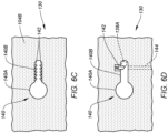
- FIG. 6C illustrates a slot portion 140B of a slotted aperture 140 having directional features (e.g., elastically deformable teeth) that allow the stem 138A to travel into the slot portion 140B but inhibit stem 138A travel out of the slot portion 140B.
- FIG. 6D illustrates another example wherein a slotted aperture 140 includes a biased lock mechanism 142. As the stem 138A travels within the slot portion 140B and engages the biased lock mechanism 142, the biased lock mechanism retracts, allowing the stem 138A to pass.
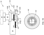
- FIGS. 7 and 7A diagrammatically illustrate a present disclosure locking mechanism 130 embodiment that includes a first and second retainer ring 104 coupled together with one of more mechanical fasteners 146.
- the second retainer ring 104 does not include a radial member 104B configured to engage with the radial member 102A of the first retainer ring 102.
- the first retainer ring 102 includes a flange 102C extending axially outward past the first retainer ring radial member 102B and the second retainer ring 104 is configured to align with the flange 102C.
- One or more mechanical fasteners 146 extend through the second retainer ring 104 and into the first retainer ring flange 102C to secure the first and second retainer rings 102, 104 together.
- the mechanical fasteners 146 may be installed through the first retainer ring flange 102C and extend into the second retainer ring 104 to secure the first and second retainer rings 102, 104 together.
- the tensile loadings symbolized by the dashed lines 126, 128 in FIG. 4C are understood to also apply to this locking mechanism 130 embodiment.
- FIGS. 9-9B diagrammatically illustrate a present disclosure locking mechanism 130 embodiment that includes at least one biased detent member 148 engaged with the radial member 102B of the first retainer ring 102 and at least on detent member aperture 150 disposed in the radial member 104B of the second retainer ring 104.
- the detent member 148 has a spherical configuration (e.g., a spherical ball) and in FIG. 9A , the detent member 148 has a "T" shaped configuration.
- the present disclosure is not limited to these detent member 148 configurations.
- the detent member 148 is at least partially disposed in a pocket 152 within the radial member 102B of the first retainer ring 102.
- a biasing spring 154 is also disposed within the pocket 152 and is positioned to bias the detent member 148 toward the second retainer ring 104.
- the detent member aperture 150 and the detent member 148 are collectively configured such that a portion of the detent member 148 is able to extend into the second retainer ring 104 detent member aperture 150. When the portion of the detent member 148 extends into the detent member aperture 150, rotation of the second retainer ring 104 relative to the first retainer ring 102 (or vice versa) is inhibited or prevented.
- the first retainer ring 102 may be torqued relative to the shaft 54. Subsequently, a detent member 148 and a biasing spring 154 may be disposed in each first retainer ring pocket 152. The second retainer ring 104 may then be torqued relative to the shaft 54. The second retainer ring 104 is finally positioned so that the pockets 152 in the first retainer ring radial member 102B align with the detent members 148. Once aligned, a portion of each detent member 148 is biased into a respective detent member aperture 150. Thereafter, the detent members 148 inhibit or prevent relative movement between the first and second retainer rings 102, 104.
- first and second retainer rings 102, 104 may be coupled (e.g., prior to torquing the first and second retainer rings 102, 104 onto the shaft 54) with a detent member 148 and a biasing spring 154 being disposed in each first retainer ring pocket 152.
- the first and second retainer rings 102, 104 may then be torqued relative to the shaft 54.
- the second retainer ring 104 may be rotated relative to the first retainer ring 102 (i.e., either forward or backward) as required so that the detent members 148 are received within respective detent member apertures 150.
- the locking mechanism 130 embodiment shown in FIG. 9B includes a retention plate 156 attached to the radial member 102B of the first retainer ring 102.
- the retention plate 156 maintains the biased detent members 148 within the first retainer ring pockets 152 during assembly.
- the retention plate 156 is configured to permit a portion of the detent members 148 sufficient to engage with the second retainer ring 104 detent member apertures 150 to extend outwardly beyond the retention plate 156.
- the retention plate 156 may be attached to the first retainer ring 102 by mechanical fasteners or by any other means.
- FIG. 10 diagrammatically illustrates a present disclosure locking mechanism 130 embodiment wherein the radial member of the first retainer ring 102 and the second retainer ring 104 are attached to one another by spot weld 158 (or braze, or solder, or adhesive, or the like).
- spot weld 158 or braze, or solder, or adhesive, or the like.
- the first retainer ring 102 may be torqued relative to the shaft 54.
- the second retainer ring 104 may be torqued relative to the shaft 54.
- one or more spot welds 158 may be applied to the first and second retainer rings 102, 104 thereby bonding them together.
- the spot weld(s) 158 prevent relative movement between the first and second retainer rings 102, 104.
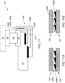
- FIGS. 11-11B diagrammatically illustrate a present disclosure locking mechanism 130 embodiment that includes a first retainer ring 102 having a first set of deformable features 160A and a second retainer ring 104 having a second set of deformable features 160B.
- one of the first retainer ring 102 or the second retainer ring 104 may have a set of deformable features and the other retainer ring 102, 104 may have a set of non-deformable features.
- This embodiment is described hereinafter as both retainer rings 102, 104 having deformable features but the present disclosure is not limited thereto.
- the first and second sets of deformable features 160A, 160B are configured to be elastically deformable when engaged with one another in a first direction, and configured to prevent relative motion when engaged with one another in a second direction, opposite the first direction.
- FIG. 11A diagrammatically illustrates the first retainer ring 102 and first set of deformable features 160A traveling in a first direction and the second retainer ring 104 and second set of deformable features 160B traveling in the opposite second direction.
- one of the first and second retainer rings 102, 104 may be stationary and the other moving to create the same relative movement.
- the first and second sets of deformable features 160A, 160B (shown as teeth-like structures, but not limited thereto) will deform to allow the depicted relative movement.
- FIG. 11A diagrammatically illustrates the first retainer ring 102 and first set of deformable features 160A traveling in a first direction and the second retainer ring 104 and second set of deformable features 160B traveling in the opposite second direction.
- FIG. 11B illustrates the first and second sets of deformable features 160A, 160B engaged with one another in a manner that prevents relative movement.
- the positioning between the first and second sets of deformable features 160A, 160B will occur within a short amount of relative travel in the direction opposite that shown in FIG. 11A .
- the configuration and orientation of the first and second sets of deformable features 160A, 160B shown in FIGS. 11A and 11B are provided for illustration purposes and are not intended to be limiting.
- the first retainer ring 102 may be torqued relative to the shaft 54.
- the second retainer ring 104 may then be torqued relative to the shaft 54.
- the first and second sets of deformable features 160A, 160B engage with one another.
- One or both of the first and second sets of deformable features 160A, 160B deform and thereby permit the relative movement. Relative movement between the first and second retainer rings 102, 104 in the opposite direction is inhibited or prevented by the respective sets of deformable features 160A, 160B.
- locking mechanisms 130 are intended to illustrate the scope of the present disclosure and are not intended to be limiting.
- any one of these structures may describe the operations as a sequential process, many of the operations can be performed in parallel or concurrently.
- the order of the operations may be rearranged.
- a process may correspond to a method, a function, a procedure, a subroutine, a subprogram, etc.
- the terms “comprise”, “comprising”, or any other variation thereof, are intended to cover a non-exclusive inclusion, such that a process, method, article, or apparatus that comprises a list of elements does not include only those elements but may include other elements not expressly listed or inherent to such process, method, article, or apparatus.
Landscapes
- Engineering & Computer Science (AREA)
- General Engineering & Computer Science (AREA)
- Mechanical Engineering (AREA)
- Mounting Of Bearings Or Others (AREA)
Abstract
Description
- The invention relates to rotating shafts in general and to apparatus for securing bearings relative to a rotating shaft in particular.
- Turbomachines, such as gas turbine engines, typically include fan, compressor, combustor, and turbine sections. The fan section drives air along a core flow path into the compressor section. The compressed air is mixed with fuel and combusted in the combustor section. The products of combustion are expanded in the turbine section.
- A typical turbine engine has two or three shafts (sometimes referred to as "spools") that transmit torque between the turbine and compressor sections of the engine. Each of these shafts is typically supported by bearings. In some applications, a shaft bearing may be configured to accommodate both axial and radial loads. In other applications, a shaft bearing may be configured to accommodate only an axial load. Turbine engines also often include a gearbox (e.g., and accessory gearbox) driven off of one of the engine shafts. An accessory gearbox may be used to drive an electric generator, a hydraulic pump, an oil pump, or any combination thereof.
- For various reasons, including but not limited to vibration and loading, shaft bearings may undesirably "walk" from their original location. It is desirable to have a structure that prevents bearing movement, and in particular a structure that is easily manufactured and implemented, and one that is cost effective.
- According to an aspect of the invention a shaft bearing retainer assembly is provided that includes an axially extending shaft, a bearing, and a bearing retainer subassembly. The shaft has a first radial surface, a second radial surface, a distal end, a bearing seat, and a retainer cavity. The first radial surface is opposite the second radial surface. The bearing seat is engaged with the first radial surface and extends axially inward from the distal end. The retainer cavity is disposed in the second radial surface of the shaft and extends axially inward from the distal end. The shaft includes a first threaded surface portion disposed in the retainer cavity and a second threaded surface portion in the second radial surface. The bearing has a race and a plurality of roller elements. The bearing race is mounted in the bearing seat. The bearing retainer subassembly includes a first retainer ring and a second retainer ring. The first retainer ring is in threaded engagement with the first threaded surface portion and engaged with the bearing race. The second retainer ring is in threaded engagement with the second threaded surface portion and engaged with the first retainer ring.
- In any of the aspects or embodiments described above and herein, the threaded engagement between the first retainer ring and the first threaded surface portion is a first threaded engagement, and the threaded engagement between the second retainer ring and the second threaded surface portion is a second threaded engagement, and the first threaded engagement may be different than the second threaded engagement.
- In any of the aspects or embodiments described above and herein, the first threaded engagement has a first threads per inch value (first thread pitch value), and the second threaded engagement has a second threads per inch value (second thread pitch value), and the first threads per inch value (first thread pitch value) may be different than the second threads per inch value (second thread pitch value).
- In any of the aspects or embodiments described above and herein, the first threaded engagement may have a left-handed thread and the second threaded engagement may have a right-handed thread, or the first threaded engagement may have a right-handed thread and the second threaded engagement may have a left-handed thread.
- In any of the aspects or embodiments described above and herein, the first retainer ring (FRR) may have a FRR axial member, a FRR radial member, and a FRR threaded collar, and the FRR threaded collar may be disposed adjacent a first axial end of the FRR axial member and the FRR radial member may extend radially out from the FRR axial member at a second axial end of the FRR axial member, and the FRR threaded collar may be in threaded engagement with the first threaded surface portion.
- In any of the aspects or embodiments described above and herein, the second retainer ring (SRR) may have a SRR axial member, a SRR radial member, and a SRR threaded collar, and the SRR threaded collar may be disposed adjacent a first axial end of the SRR axial member and the SRR radial member may extend radially out from the SRR axial member at a second axial end of the SRR axial member, and the SRR threaded collar may be in threaded engagement with the second threaded surface portion.
- In any of the aspects or embodiments described above and herein, the bearing seat (BS) may include an axially extending bearing mount surface and a BS shoulder surface, and the axially extending bearing mount surface may extend from the distal end to the BS shoulder surface and the BS shoulder surface may extend between the bearing mount surface and the shaft outer radial surface.
- In any of the aspects or embodiments described above and herein, the bearing seat (BS) may be defined by a shoulder protrusion extending outwardly from the first radial surface and a portion of the radial surface extending between the shoulder protrusion and the shaft distal end.
- In any of the aspects or embodiments described above and herein, the retainer cavity (RC) may include an RC inner diameter surface and an RC shoulder surface, and the RC inner diameter surface may extend from the distal end to the RC shoulder surface and the RC shoulder surface may extend between the RC inner diameter surface and the shaft inner radial surface.
- In any of the aspects or embodiments described above and herein, the shaft bearing retainer assembly may include a locking mechanism configured to inhibit relative rotation between the first retainer ring and the second retainer ring.
- In any of the aspects or embodiments described above and herein, the locking mechanism may include at least one locking key engaged with the first retainer ring and the second retainer ring.
- In any of the aspects or embodiments described above and herein, the locking mechanism may include at least one lock post extending out from the first retainer ring and a slotted aperture disposed in the second retainer ring, and the lock post may include a stem and a head, and the slotted aperture may include a receiver portion and a slot portion, and the slotted aperture may include a stem locking feature.
- In any of the aspects or embodiments described above and herein, the locking mechanism may include at least one mechanical fastener engaged with the first retainer ring and the second retainer ring.
- In any of the aspects or embodiments described above and herein, the locking mechanism may include at least one biased detent member engaged between the first retainer ring and the second retainer ring.
- In any of the aspects or embodiments described above and herein, the locking mechanism may include a deformable feature attached to one of the first retainer ring or the second retainer ring, the deformable feature configured to engage with the other of the first retainer ring or the second retainer ring to inhibit relative rotation between the first retainer ring and the second retainer ring.
- In any of the aspects or embodiments described above and herein, the shaft first radial surface may be an outer radial surface of the shaft, and the shaft second radial surface may be an inner radial surface of the shaft, or the shaft first radial surface may be an inner radial surface of the shaft, and the shaft second radial surface may be an outer radial surface of the shaft.
- According to another aspect of the invention, a bearing assembly for a rotating shaft is provided. The shaft having a first radial surface, a second radial surface, and a distal end. The first radial surface is opposite the second radial surface. The second radial surface has a first SRR portion disposed at a first diameter and a second SSR portion disposed at a second diameter. The first diameter is different than the second diameter. The bearing assembly includes a first threaded surface portion, a second threaded surface portion, a bearing, and a bearing retainer assembly. The first threaded surface portion is disposed on the first SRR portion of the second radial surface. The second threaded surface portion is disposed on the second SRR portion of the second radial surface. The bearing has a race and a plurality of roller elements. The bearing race is mounted on the first radial surface. The bearing retainer assembly includes a first retainer ring and a second retainer ring. The first retainer ring is in threaded engagement with the first SRR portion and engaged with the bearing race. The second retainer ring is in threaded engagement with the second SRR portion and engaged with the first retainer ring. The threaded engagement between the first retainer ring and the first threaded surface portion is a first threaded engagement, and the threaded engagement between the second retainer ring and the second threaded surface portion is a second threaded engagement. The first threaded engagement is different than the second threaded engagement.
- In any of the aspects or embodiments described above and herein, the first threaded engagement has a first threads per inch value (first thread pitch value), and the second threaded engagement has a second threads per inch value (second thread pitch value), and the first threads per inch value (first thread pitch value) may be different than the second threads per inch value (second thread pitch value).
- In any of the aspects or embodiments described above and herein, the first threaded engagement may have a left-handed thread and the second threaded engagement may have a right-handed thread, or the first threaded engagement may have a right-handed thread and the second threaded engagement may have a left-handed thread.
- The foregoing features and elements may be combined in various combinations without exclusivity, unless expressly indicated otherwise. For example, aspects and/or embodiments of the present disclosure may include any one or more of the individual features or elements disclosed above and/or below alone or in any combination thereof. These features and elements as well as the operation thereof will become more apparent in light of the following description and the accompanying drawings. It should be understood, however, the following description and drawings are intended to be exemplary in nature and non-limiting.
-
-
FIG. 1 is a diagrammatic sectional view of a gas turbine engine. -
FIG. 2 is a diagrammatic view of a bearing mounted on a shaft with a present disclosure shaft bearing retainer assembly embodiment. -
FIG. 2A is a diagrammatic view of a bearing mounted on a shaft with a present disclosure shaft bearing retainer assembly embodiment. -
FIG. 2B is a diagrammatic view of a bearing mounted on a shaft with a present disclosure shaft bearing retainer assembly embodiment. -
FIG. 3 is a diagrammatic representation of a first retainer ring embodiment and a second retainer ring embodiment. -
FIGS. 4-4B diagrammatically illustrate an example of an assembly sequence of a present disclosure shaft bearing retainer assembly. -
FIG. 4C diagrammatically illustrates torque loadings associated with embodiments of the present disclosure shaft bearing retainer assembly. -
FIG. 5 is a diagrammatic view of a bearing mounted on a shaft with a present disclosure bearing shaft retainer assembly embodiment, including a locking mechanism embodiment.FIG. 5A is an end view showing a portion of the shaft bearing retainer assembly and locking mechanism shown inFIG. 5 . -
FIG. 6 is a diagrammatic view of a bearing mounted on a shaft with a present disclosure shaft bearing retainer assembly embodiment with the second retainer ring separated, and a locking mechanism embodiment. -
FIG. 6A illustrates the present disclosure shaft bearing retainer assembly embodiment shown inFIG. 6 , now with the second retainer ring separated engaged. -
FIG. 6B is a diagrammatic view of the second retainer shown inFIGS. 6 and6A . -
FIGS. 6C and 6D illustrates different embodiments of a slotted aperture. -
FIG. 7 is a diagrammatic view of a bearing mounted on a shaft with a present disclosure shaft bearing retainer assembly embodiment, including a locking mechanism embodiment.FIG. 7A is an end view showing a portion of the bearing retainer assembly and locking mechanism shown inFIG. 7 . -
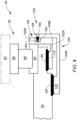
FIG. 8 is a diagrammatic view of a bearing mounted on a shaft with a present disclosure shaft bearing retainer assembly embodiment, including a locking mechanism embodiment.FIG. 8A is an end view showing a portion of the bearing retainer assembly and locking mechanism shown inFIG. 8 . -
FIGS. 9-9B are diagrammatic views of a bearing mounted on a shaft with a present disclosure shaft bearing retainer assembly embodiment, including locking mechanism embodiments. -
FIG. 10 is a diagrammatic view of a bearing mounted on a shaft with a present disclosure shaft bearing retainer assembly embodiment, including a locking mechanism embodiment. -
FIG. 11 is a diagrammatic view of a bearing mounted on a shaft with a present disclosure shaft bearing retainer assembly embodiment, including a locking mechanism embodiment.FIGS. 11A and 11B diagrammatically illustrate the locking mechanism embodiment shown inFIG. 11 . -
FIG. 1 shows a partially sectioned diagrammatic view of a gearedgas turbine engine 20. Thegas turbine engine 20 extends along anaxial centerline 22 between an upstreamair flow inlet 24 and a downstreamair flow exhaust 26. Thegas turbine engine 20 includes afan section 28, acompressor section 30, acombustor section 32, aturbine section 34, and an accessory gearbox 33. Thecombustor section 32 includes acombustor 35. Thecompressor section 30 includes a low pressure compressor (LPC) 36 and a high pressure compressor (HPC) 38. Theturbine section 34 includes a high pressure turbine (HPT) 40 and a low pressure turbine (LPT) 42. The engine sections are arranged sequentially along thecenterline 22. Thefan section 28 is connected to a gearedarchitecture 44, for example, through afan shaft 46. The gearedarchitecture 44 and theLPC 36 are connected to and driven by theLPT 42 through alow speed shaft 48. TheHPC 38 is connected to and driven by theHPT 40 through ahigh speed shaft 50. - The accessory gearbox 33 may be driven off of the
low speed shaft 48 or thehigh speed shaft 50; e.g., by a tower shaft. Accessory gearboxes often include internal shafts. The accessory gearbox 33 may be used to drive peripheral equipment such as an electric generator, a hydraulic pump, an oil pump, and the like or combinations thereof. The present disclosure is not limited to any particular accessory gearbox configuration. Theaforesaid shafts bearings 52. The terms "forward", "leading", "aft, "trailing" are used herein to indicate the relative position of a component or surface. As core gas air passes through theengine 20, a "leading edge" of a stator vane or rotor blade encounters core gas air before the "trailing edge" of the same. In a conventional axial engine such as that shown inFIG. 1 , thefan section 28 is "forward" of thecompressor section 30 and theturbine section 34 is "aft" of thecompressor section 30. The terms "inner radial" and "outer radial" refer to relative radial positions from theengine centerline 22. An inner radial component or path is disposed radially closer to theengine centerline 22 than an outer radial component or path. Thegas turbine engine 20 diagrammatically shown is an example provided to facilitate the description herein. The present disclosure is not limited to any particular gas turbine engine configuration. The various embodiments of the present disclosure shaft bearing assembly described herein may be used in a variety of different applications; e.g., within a turbine engine, within a gearbox, and the like. The present disclosure shaft bearing retainer assembly has particular utility in applications having limited space adjacent the distal end of a shaft to secure a bearing engaged with the shaft. Accessory gearboxes used with aircraft turbine engines are a specific example of an application that very often has limited space adjacent the distal end of a shaft. Consequently, the present disclosure is understood to have particular utility in accessory gearbox applications. -
FIGS. 2 and2A diagrammatically illustrate an embodiment of a present disclosure shaft bearingretainer assembly 53 that includes ashaft 54 rotatable about anaxial centerline 56, abearing 52, and a bearingretainer subassembly 60. The present disclosure shaft bearingretainer assembly 53 may include astructural component 62, or may be utilized with astructural component 62. The term "shaft 54" as used herein refers to a shaft that may be present within aturbine engine 20, or a gearbox (e.g., an accessory gearbox 33), or the like, and is not limited to any particular shaft application.FIG. 2 illustrates the bearing 52 disposed radially outside of theshaft 54. Alternatively, the bearing 52 may be disposed radially inside of theshaft 54 as shown inFIG. 2A . To facilitate the description herein, the present disclosure is detailed herein in terms of abearing 52 disposed radially outside of theshaft 54 and other components relative to a outerradial bearing 52. The present disclosure is not, however, limited to anouter bearing 52 construct. Thebearing 52 includes aninner race 64, anouter race 66, and a plurality ofroller elements 68 disposed between the inner andouter races particular bearing 52 configuration other than one having inner andouter races roller elements 68. For example, theroller elements 68 are shown as cylindrical but the present disclosure is not limited to anyparticular roller element 68 configuration; e.g., theroller elements 68 may be spherical tapered roller elements, and the like. Thebearing 52 may be configured to accommodate axial loads, or radial loads, or any combination thereof. The bearinginner race 64 includes aninner diameter surface 70, aroller element surface 72, a firstlateral surface 74, and a secondlateral surface 76. The first and second lateral surfaces 74, 76 are opposite one another and extend between theinner diameter surface 70 and theroller element surface 72. - The
structural component 62 shown (in dashed lines) radially outside of thebearing 52 may be a static structure (e.g., stationary relative to the shaft 54) or a rotational structure (e.g., capable of rotation relative to the shaft 54). In those embodiments wherein the present disclosure includes abearing 52 disposed radially inside of the shaft 54 (e.g., seeFIG. 2A ), the structural component is disposed radially inside of thebearing 52. Thestructural component 62 is engaged with the bearingouter race 66. The present disclosure is not limited to any particularstructural component 62 disposed radially outside of thebearing 52. - The
shaft 54 has an annular configuration that extends axially. Theshaft 54 includes an outerradial surface 78, an innerradial surface 80, adistal end 82, and aninner cavity 84. The innerradial surface 80 defines the shaftinner cavity 84. In the embodiments shown inFIGS. 2 and4-11 , theshaft 54 further includes a bearingseat 86 disposed in the outerradial surface 78 of theshaft 54, extending axially inward from thedistal end 82 of theshaft 54. The bearingseat 86 is defined by an axially extending bearingmount surface 88, and ashoulder surface 90 extending radially between the bearingmount surface 88 and the shaft outerradial surface 78.FIG. 2B diagrammatically illustrates ashoulder protrusion 85 extending out from the outer radial surface of theshaft 54. Theshoulder protrusion 85 and the portion of the shaft outerradial surface 78 extending between thedistal end 82 and theshoulder protrusion 85 is analternative bearing seat 86 for positioning the bearinginner race 64. Theshaft 54 further includes aretainer cavity 92 disposed in the innerradial surface 80 of theshaft 54, extending axially inward from thedistal end 82 of theshaft 54. The retainer cavity 92 (RC) is defined by an axially extending RCinner diameter surface 94, and anRC shoulder surface 96 extending radially between the RCinner diameter surface 94 and the shaft inner radial surface 80 (seeFIG. 2 ). All or a portion of the RCinner diameter surface 94 may be threaded. The threadedportion 98 of the RCinner diameter surface 94 is configured (e.g., type of thread, threads per inch (TPI), and the like) for threaded engagement with afirst retainer ring 102 as detailed herein. A portion of the shaft innerradial surface 80 may be threaded. In the embodiment diagrammatically shown inFIG. 2 , the threadedportion 100 of the shaft innerradial surface 80 is disposed adjacent theRC shoulder surface 96. The threadedportion 100 of the shaft innerradial surface 80 is configured (e.g., type of thread, threads per inch (TPI), and the like) for engagement with a threaded portion of thesecond retainer ring 104 as will be detailed herein. - Referring to
FIGS. 2 and3 , the bearingretainer subassembly 60 includes afirst retainer ring 102 and asecond retainer ring 104. Thefirst retainer ring 102 includes anaxial member 102A and aradial member 102B. Theaxial member 102A extends axially between a firstaxial end 106 and a secondaxial end 108. Theradial member 102B extends radially between an outerradial end 110 and an innerradial end 112. Theradial member 102B is connected to or integral with theaxial member 102A. To facilitate the description herein, theradial member 102B and theaxial member 102A will be described as connected, but the present disclosure is not limited to any particular connection configuration; e.g., integrally connected, mechanically connected, and the like. In the embodiment shown inFIGS. 2 and3 , the innerradial end 112 of theradial member 102B extends outwardly from the secondaxial end 108 of theaxial member 102A. The present disclosure is not limited to this particularaxial member 102A /radial member 102B configuration; e.g., as detailed herein the present disclosure contemplates variousaxial member 102A /radial member 102B configurations. In the embodiment shown inFIGS. 2 and3 , theradial member 102B is substantially perpendicular to theaxial member 102A but the present disclosure is not limited to aradial member 102B that is perpendicular to theaxial member 102A. As will be detailed herein, the first retainerring radial member 102B is configured to engage with the secondlateral surface 76 of the bearinginner race 64. - The
first retainer ring 102 includes a threadedcollar 114 disposed at or adjacent to the firstaxial end 106 of theaxial member 102A. The threadedcollar 114 includes a threaded surface configured (e.g., type of thread, threads per inch (TPI), and the like) for engagement with a threaded portion of theshaft 54; e.g., engagement with the threadedportion 98 of the RCinner diameter surface 94. - In the embodiment shown in
FIGS. 2 and3 , the first and second retainer rings 102, 104 are similarly configured; i.e., thesecond retainer ring 104 includes anaxial member 104A and aradial member 104B, and theradial member 104B is connected to theaxial member 104A. In thesecond retainer ring 104 embodiment shown inFIGS. 2 and3 , the innerradial end 116 of theradial member 104B is connected to the secondaxial end 118 of theaxial member 104A, and theradial member 104B extends radially outward from theaxial member 104A to its outerradial end 120. Like thefirst retainer ring 102, thesecond retainer ring 104 has aradial member 104B that is substantially perpendicular to theaxial member 102A. Thesecond retainer ring 104 includes a threadedcollar 122 disposed at or adjacent to the firstaxial end 124 of theaxial member 104A. The threadedcollar 122 includes a threaded surface configured (e.g., type of thread, threads per inch (TPI), and the like) for engagement with a threaded portion of theshaft 54; e.g., engagement with the threadedportion 100 of the shaft innerradial surface 80. - Referring to
FIGS. 4-4C , the following non-limiting example of how a present disclosure bearing 52 and bearingretainer subassembly 60 may be assembled onto ashaft 54 illustrates advantages provided by the present disclosure.FIG. 4 illustrates abearing 52 mounted on the bearingmount surface 88 of theshaft 54. Typically, the bearinginner race 64 is press fit onto the bearingmount surface 88 and the firstlateral surface 74 of the bearinginner race 64 is engaged with the bearingseat shoulder surface 90. As can be seen inFIG. 4 , theshaft 54 includes aretainer cavity 92, a threadedportion 98 of the RCinner diameter surface 94, and a threadedportion 100 of the shaft innerradial surface 80. -
FIG. 4A illustrates thesame shaft 54 and bearing 52 arrangement as shown inFIG. 4 and now also diagrammatically includes afirst retainer ring 102. Thefirst retainer ring 102 is torqued onto theshaft 54 via the threaded engagement between the threadedportion 98 of the RCinner diameter surface 94 and the threadedcollar 114 of thefirst retainer ring 102. Theradial member 102B of thefirst retainer ring 102 is engaged with the secondlateral surface 76 of the bearinginner race 64. When thefirst retainer ring 102 is torqued onto theshaft 54 in this manner, the portion of theshaft 54 disposed radially inside of thebearing 52 is under tension and thefirst retainer ring 102radial member 102B applies a retaining force (e.g., a biasing force) against the bearinginner race 64. Dashedline 126 shown inFIG. 4C is intended to symbolize the loading created by torquing the first retainer onto theshaft 54. -
FIG. 4B illustrates thesame shaft 54 and bearing 52 arrangement shown inFIGS. 4 and 4A and now also includes asecond retainer ring 104. Thesecond retainer ring 104 is torqued onto theshaft 54 via the threaded engagement between the threadedportion 100 of the shaft innerradial surface 80 and the threadedcollar 122 of thesecond retainer ring 104. Theradial member 104B of thesecond retainer ring 104 is engaged with theradial member 102B of thefirst retainer ring 102. When thesecond retainer ring 104 is torqued onto theshaft 54 in this manner, a portion of theshaft 54 axially beyond the bearing 52 is under tension. The tension applied to the axially beyond portion of theshaft 54 is understood to counter the tension applied to the portion of theshaft 54 disposed radially inside of thebearing 52. Dashedline 128 shown inFIG. 4C is intended to symbolize the loading created by torquing thesecond retainer ring 104 onto theshaft 54. The second retainerring radial member 104B applies a retaining force (e.g., a biasing force) against the first retainerring radial member 102B. - As indicated above, the threaded
collar 114 of thefirst retainer ring 102 is in threaded engagement with the threadedportion 98 of the RC inner diameter surface 94 (i.e., a first threaded engagement), and the threadedcollar 122 of thesecond retainer ring 104 is in threaded engagement with the threadedportion 100 of the shaft inner radial surface 80 (i.e., a second threaded engagement). In some embodiments, the first and second threaded engagements may be dissimilar to decrease the potential of either thefirst retainer ring 102 or thesecond retainer ring 104 loosening; e.g., unthreading. As a non-limiting example, the first threaded engagement may be configured to have ten (10) threads per inch (thread pitch of 2.54 mm), and the second threaded engagement may be configured to have eight (8) threads per inch (thread pitch of 3.175 mm). In this non-limiting example, for every rotation, thesecond retainer ring 104 travels axially one-eighth of an inch (0.125 inches) (3.175 mm) relative to theshaft 54. In contrast, for every rotation, thefirst retainer ring 102 travels axially one-tenth of an inch (0.10 inches) (2.54 mm) relative to theshaft 54. Hence, the first retainer ring 102 (FRR) and the second retainer ring 104 (SRR) travel axially at different rates. The effective pitch between the two threaded engagements may be algorithmically characterized as follows:
first retainer ring 102 and where "PSRR" is the threads per inch for the second retainer ring. Using the non-limiting example data:
- The Effective Pitch is forty (40) and the "gain" (a measure of the mechanical advantage provided) is 40/10 = 4. Hence, using the example thread characteristics, the present disclosure yields a tensile preload that is four (4) times greater than a fastener (e.g., a lock nut) applied to the
shaft 54 to secure the bearinginner race 64 that utilizes a ten (10) threads per inch (thread pitch of 2.54 mm) configuration. Another advantage of the present disclosure is that the first and second threaded engagements can be manipulated to increase or decrease the gain to a desired level for the application at hand. In some embodiments, the first and second threaded engagements may be oppositely threaded; e.g., the first threaded engagement may be configured to a right-handed thread and the second threaded engagement may be configured to have a left-handed thread, or vice versa. - As will be detailed herein, embodiments of the present disclosure may use a
locking mechanism 130 to lock thefirst retainer ring 102 and thesecond retainer ring 104 to prevent relative motion therebetween. The present disclosure contemplates that a number ofdifferent locking mechanisms 130 may be utilized. -
FIGS. 5 and 5A diagrammatically illustrate a presentdisclosure locking mechanism 130 embodiment that includes at least one lockingkey 132 that is disposed to engage both thefirst retainer ring 102 and thesecond retainer ring 104. The example shown inFIGS. 5 and 5A includes four (4) lockingkeys 132. The lockingkeys 132 may be received within apertures or other openings disposed in the first and second retainer rings 102, 104. The lockingkeys 132 may be connected to one another with asnap ring 134 or other mechanical fastener. In some embodiments (e.g., seeFIG. 5A ), thesecond retainer ring 104 may include protrusions 136 (e.g., "snap ring seats 136") configured to support and/or position a mechanical fastener such as asnap ring 134. To utilize thislocking mechanism 130 embodiment, the first and second retainer rings 102, 104 are torqued relative to theshaft 54 as described above. The apertures (or other openings) disposed in thefirst retainer ring 102 and thesecond retainer ring 104 are aligned and the lockingkeys 132 are inserted. As indicated, the lockingkeys 132 may be connected to one another with a mechanical fastener; e.g., asnap ring 134. -
FIGS. 6-6D diagrammatically illustrate a presentdisclosure locking mechanism 130 embodiment that includes afirst retainer ring 102 having at least onelock post 138 and asecond retainer ring 104 having one or more slotted apertures 140 (seeFIG. 6B ). Thelock post 138 embodiment shown inFIG. 6 has astem 138A and ahead 138B that is larger than thestem 138A; e.g., greater in diameter. The slottedaperture 140 includes areceiver portion 140A configured to receive a lock post 138 (lockpost head 138B allowed to pass through) and anarrower slot portion 140B configured to receive a lock post stem 138A. The geometry of theslot portion 140B does not permit thelock post head 138A to pass axially through theslot portion 140B. To utilize thislocking mechanism 130 embodiment, thefirst retainer ring 102 may be torqued relative to theshaft 54 and thesecond retainer ring 104 may be torqued relative to theshaft 54. As thesecond retainer ring 104 draws close to thefirst retainer ring 102, the lock posts 138 are received within the slottedapertures 140 until each respectivelock post stem 138 is received within arespective slot portion 140B of a slottedaperture 140. Alternatively, the first and second retainer rings 102, 104 may be coupled with one another so that therespective lock posts 138 are received withinrespective receiver portions 140A of respective slottedapertures 140. The first and second retainer rings 102, 104 may then be torqued relative to theshaft 54. When the appropriate amount of torque for thefirst retainer ring 102 is achieved, thesecond retainer ring 104 is either torqued an additional amount so that the lock post stems 138 are received within theslot portions 140B of slottedaperture 140, or thesecond retainer ring 104 is backed off (i.e., rotated) so that the lock post stems 138 are received within theslot portions 140B of slottedapertures 140. Either way, the lock post heads 138 maintain the first and second retainer rings 102, 104 engaged with one another.FIG. 6B diagrammatically illustrates the first and second retainer rings 102, 104 engaged with one another. This presentdisclosure locking mechanism 130 embodiment is not limited to this assembly example. - Referring to
FIGS. 6C and 6D , in some embodiments astem locking feature 142 may be included that inhibits or prevents thestem 138A from traversing out of theslot portion 140B of the slottedaperture 140.FIG. 6C , for example, illustrates aslot portion 140B of a slottedaperture 140 having directional features (e.g., elastically deformable teeth) that allow thestem 138A to travel into theslot portion 140B but inhibitstem 138A travel out of theslot portion 140B.FIG. 6D illustrates another example wherein a slottedaperture 140 includes abiased lock mechanism 142. As thestem 138A travels within theslot portion 140B and engages thebiased lock mechanism 142, the biased lock mechanism retracts, allowing thestem 138A to pass. After thestem 138A has passed, thebiased lock mechanism 142 moves into theslot portion 140B behind thestem 138A, thereby preventing thestem 138A from withdrawing from theslot portion 140B. In some embodiments (e.g., as shown inFIG. 6D ), thebiased lock mechanism 142 may include anactuation port 144 that allows insertion of a tool to retract thebiased lock mechanism 142 to permit thestem 138A to be moved out of the slottedportion 140B. -
FIGS. 7 and 7A diagrammatically illustrate a presentdisclosure locking mechanism 130 embodiment that includes a first andsecond retainer ring 104 coupled together with one of moremechanical fasteners 146. In this embodiment, thesecond retainer ring 104 does not include aradial member 104B configured to engage with theradial member 102A of thefirst retainer ring 102. In this embodiment, thefirst retainer ring 102 includes aflange 102C extending axially outward past the first retainerring radial member 102B and thesecond retainer ring 104 is configured to align with theflange 102C. One or more mechanical fasteners 146 (e.g., rivets, screws, bolts and the like) extend through thesecond retainer ring 104 and into the firstretainer ring flange 102C to secure the first and second retainer rings 102, 104 together. Conversely, themechanical fasteners 146 may be installed through the firstretainer ring flange 102C and extend into thesecond retainer ring 104 to secure the first and second retainer rings 102, 104 together. The tensile loadings symbolized by the dashedlines FIG. 4C are understood to also apply to thislocking mechanism 130 embodiment. -
FIGS. 8 and 8A diagrammatically illustrate another presentdisclosure locking mechanism 130 embodiment that utilizes one of moremechanical fasteners 146. In this embodiment, the one or more mechanical fasteners 146 (e.g., rivets, screws, bolts and the like) extend through the second retainerring radial member 104B and into the first retainerring radial member 102B to secure the first and second retainer rings 102, 104 together. The tensile loadings symbolized by the dashedlines FIG. 4C are understood to also apply to thislocking mechanism 130 embodiment. -
FIGS. 9-9B diagrammatically illustrate a presentdisclosure locking mechanism 130 embodiment that includes at least onebiased detent member 148 engaged with theradial member 102B of thefirst retainer ring 102 and at least ondetent member aperture 150 disposed in theradial member 104B of thesecond retainer ring 104. InFIG. 9 , thedetent member 148 has a spherical configuration (e.g., a spherical ball) and inFIG. 9A , thedetent member 148 has a "T" shaped configuration. The present disclosure is not limited to thesedetent member 148 configurations. Thedetent member 148 is at least partially disposed in apocket 152 within theradial member 102B of thefirst retainer ring 102. A biasingspring 154 is also disposed within thepocket 152 and is positioned to bias thedetent member 148 toward thesecond retainer ring 104. Thedetent member aperture 150 and thedetent member 148 are collectively configured such that a portion of thedetent member 148 is able to extend into thesecond retainer ring 104detent member aperture 150. When the portion of thedetent member 148 extends into thedetent member aperture 150, rotation of thesecond retainer ring 104 relative to the first retainer ring 102 (or vice versa) is inhibited or prevented. - To utilize this
locking mechanism 130 embodiment, thefirst retainer ring 102 may be torqued relative to theshaft 54. Subsequently, adetent member 148 and abiasing spring 154 may be disposed in each firstretainer ring pocket 152. Thesecond retainer ring 104 may then be torqued relative to theshaft 54. Thesecond retainer ring 104 is finally positioned so that thepockets 152 in the first retainerring radial member 102B align with thedetent members 148. Once aligned, a portion of eachdetent member 148 is biased into a respectivedetent member aperture 150. Thereafter, thedetent members 148 inhibit or prevent relative movement between the first and second retainer rings 102, 104. Alternatively, the first and second retainer rings 102, 104 may be coupled (e.g., prior to torquing the first and second retainer rings 102, 104 onto the shaft 54) with adetent member 148 and abiasing spring 154 being disposed in each firstretainer ring pocket 152. The first and second retainer rings 102, 104 may then be torqued relative to theshaft 54. When the appropriate amount of torque for thefirst retainer ring 102 is achieved, thesecond retainer ring 104 may be rotated relative to the first retainer ring 102 (i.e., either forward or backward) as required so that thedetent members 148 are received within respectivedetent member apertures 150. - The
locking mechanism 130 embodiment shown inFIG. 9B includes aretention plate 156 attached to theradial member 102B of thefirst retainer ring 102. Theretention plate 156 maintains thebiased detent members 148 within the first retainer ring pockets 152 during assembly. Theretention plate 156 is configured to permit a portion of thedetent members 148 sufficient to engage with thesecond retainer ring 104detent member apertures 150 to extend outwardly beyond theretention plate 156. Theretention plate 156 may be attached to thefirst retainer ring 102 by mechanical fasteners or by any other means. -
FIG. 10 diagrammatically illustrates a presentdisclosure locking mechanism 130 embodiment wherein the radial member of thefirst retainer ring 102 and thesecond retainer ring 104 are attached to one another by spot weld 158 (or braze, or solder, or adhesive, or the like). To utilize thislocking mechanism 130 embodiment, thefirst retainer ring 102 may be torqued relative to theshaft 54. Subsequently, thesecond retainer ring 104 may be torqued relative to theshaft 54. Once the first and second retainer rings 102, 104 are appropriately torqued, one ormore spot welds 158 may be applied to the first and second retainer rings 102, 104 thereby bonding them together. Thereafter, the spot weld(s) 158 prevent relative movement between the first and second retainer rings 102, 104. -
FIGS. 11-11B diagrammatically illustrate a presentdisclosure locking mechanism 130 embodiment that includes afirst retainer ring 102 having a first set ofdeformable features 160A and asecond retainer ring 104 having a second set of deformable features 160B. In some embodiments, one of thefirst retainer ring 102 or thesecond retainer ring 104 may have a set of deformable features and theother retainer ring deformable features FIG. 11A diagrammatically illustrates thefirst retainer ring 102 and first set ofdeformable features 160A traveling in a first direction and thesecond retainer ring 104 and second set of deformable features 160B traveling in the opposite second direction. Of course, one of the first and second retainer rings 102, 104 may be stationary and the other moving to create the same relative movement. The first and second sets ofdeformable features FIG. 11B illustrates the first and second sets ofdeformable features deformable features FIG. 11A . The configuration and orientation of the first and second sets ofdeformable features FIGS. 11A and 11B are provided for illustration purposes and are not intended to be limiting. - To utilize this
locking mechanism 130 embodiment, thefirst retainer ring 102 may be torqued relative to theshaft 54. Thesecond retainer ring 104 may then be torqued relative to theshaft 54. As thesecond retainer ring 104 draws toward thefirst retainer ring 102, the first and second sets ofdeformable features deformable features deformable features - The above examples of locking
mechanisms 130 are intended to illustrate the scope of the present disclosure and are not intended to be limiting. - While the principles of the disclosure have been described above in connection with specific apparatuses and methods, it is to be clearly understood that this description is made only by way of example and not as limitation on the scope of the disclosure. Specific details are given in the above description to provide a thorough understanding of the embodiments. However, it is understood that the embodiments may be practiced without these specific details.
- It is noted that the embodiments may be described as a process which is depicted as a flowchart, a flow diagram, a block diagram, etc. Although any one of these structures may describe the operations as a sequential process, many of the operations can be performed in parallel or concurrently. In addition, the order of the operations may be rearranged. A process may correspond to a method, a function, a procedure, a subroutine, a subprogram, etc.
- The singular forms "a," "an," and "the" refer to one or more than one, unless the context clearly dictates otherwise. For example, the term "comprising a specimen" includes single or plural specimens and is considered equivalent to the phrase "comprising at least one specimen." The term "or" refers to a single element of stated alternative elements or a combination of two or more elements unless the context clearly indicates otherwise. As used herein, "comprises" means "includes." Thus, "comprising A or B," means "including A or B, or A and B," without excluding additional elements.
- It is noted that various connections are set forth between elements in the present description and drawings (the contents of which are included in this disclosure by way of reference). It is noted that these connections are general and, unless specified otherwise, may be direct or indirect and that this specification is not intended to be limiting in this respect. Any reference to attached, fixed, connected or the like may include permanent, removable, temporary, partial, full and/or any other possible attachment option.
- As used herein, the terms "comprise", "comprising", or any other variation thereof, are intended to cover a non-exclusive inclusion, such that a process, method, article, or apparatus that comprises a list of elements does not include only those elements but may include other elements not expressly listed or inherent to such process, method, article, or apparatus.
- While various inventive aspects, concepts and features of the disclosures may be described and illustrated herein as embodied in combination in the exemplary embodiments, these various aspects, concepts, and features may be used in many alternative embodiments, either individually or in various combinations and sub-combinations thereof. Unless expressly excluded herein all such combinations and sub-combinations are intended to be within the scope of the present application. Still further, while various alternative embodiments as to the various aspects, concepts, and features of the disclosures--such as alternative materials, structures, configurations, methods, devices, and components, and so on--may be described herein, such descriptions are not intended to be a complete or exhaustive list of available alternative embodiments, whether presently known or later developed. Those skilled in the art may readily adopt one or more of the inventive aspects, concepts, or features into additional embodiments and uses within the scope of the present application even if such embodiments are not expressly disclosed herein. For example, in the exemplary embodiments described above within the Detailed Description portion of the present specification, elements may be described as individual units and shown as independent of one another to facilitate the description. In alternative embodiments, such elements may be configured as combined elements. It is further noted that various method or process steps for embodiments of the present disclosure are described herein. The description may present method and/or process steps as a particular sequence. However, to the extent that the method or process does not rely on the particular order of steps set forth herein, the method or process should not be limited to the particular sequence of steps described. As one of ordinary skill in the art would appreciate, other sequences of steps may be possible.
Claims (15)
- A shaft bearing retainer assembly comprising:an axially extending shaft (54) having a first radial surface (78), a second radial surface (80), a distal end (82), a bearing seat (86), and a retainer cavity (92), wherein the first radial surface (78) is opposite the second radial surface (80), and the bearing seat (86) is engaged with the first radial surface (78) and extends axially inward from the distal end (82), and the retainer cavity (92) is disposed in the second radial surface (80) of the shaft (54) and extends axially inward from the distal end (82), wherein the shaft (54) includes a first threaded surface portion (98) disposed in the retainer cavity (92) and a second threaded surface portion (100) in the second radial surface (80);a bearing (52) having a race (64) and a plurality of roller elements (68), wherein the bearing race (64) is mounted in the bearing seat (86); anda bearing retainer subassembly (60) that includes a first retainer ring (102) and a second retainer ring (104), wherein the first retainer ring (102) is in threaded engagement with the first threaded surface portion (98) and engaged with the bearing race (64), and the second retainer ring (104) is in threaded engagement with the second threaded surface portion (100) and engaged with the first retainer ring (102).
- The shaft bearing retainer assembly of claim 1, wherein the threaded engagement between the first retainer ring (102) and the first threaded surface portion (98) is a first threaded engagement, and the threaded engagement between the second retainer ring (104) and the second threaded surface portion (100) is a second threaded engagement, and the first threaded engagement is different than the second threaded engagement.
- The shaft bearing retainer assembly of claim 2, wherein the first threaded engagement has a first threads per inch value, and the second threaded engagement has a second threads per inch value, and the first threads per inch value is different than the second threads per inch value.
- The shaft bearing retainer assembly of claim 2 or 3, wherein the first threaded engagement has a left-handed thread and the second threaded engagement has a right-handed thread, or the first threaded engagement has a right-handed thread and the second threaded engagement has a left-handed thread.
- The shaft bearing retainer assembly of any of claims 2 to 4, wherein the first retainer ring (FRR) has a FRR axial member (102A), a FRR radial member (102B), and a FRR threaded collar (114), the FRR threaded collar (114) is disposed adjacent a first axial end (106) of the FRR axial member (102A), the FRR radial member (102B) extends radially out from the FRR axial member (102A) at a second axial end (108) of the FRR axial member (102A), and the FRR threaded collar (114) is in threaded engagement with the first threaded surface portion (98).
- The shaft bearing retainer assembly of any of claims 2 to 5, wherein the second retainer ring (SRR) has a SRR axial member (104A), a SRR radial member (104B), and a SRR threaded collar (122), the SRR threaded collar (122) is disposed adjacent a first axial end (124) of the SRR axial member (104A), the SRR radial member (104B) extends radially out from the SRR axial member (104A) at a second axial end (118) of the SRR axial member (104A), and the SRR threaded collar (122) is in threaded engagement with the second threaded surface portion (100).
- The shaft bearing retainer assembly of any of claims 2 to 6, wherein the bearing seat (BS) includes an axially extending bearing mount surface (88) and a BS shoulder surface (90), the axially extending bearing mount surface (88) extends from the distal end (82) to the BS shoulder surface (90) and the BS shoulder surface (90) extends between the bearing mount surface (88) and the shaft outer radial surface (78).
- The shaft bearing retainer assembly of any of claims 2 to 7, wherein the bearing seat (BS) is defined by a shoulder protrusion (85) extending outwardly from the first radial surface (78) and a portion of the radial surface extending between the shoulder protrusion (85) and the shaft distal end (82).
- The shaft bearing retainer assembly of any of claims 2 to 8, wherein the retainer cavity (RC) includes an RC inner diameter surface (94) and an RC shoulder surface (96), the RC inner diameter surface (94) extends from the distal end (82) to the RC shoulder surface (96) and the RC shoulder surface (96) extends between the RC inner diameter surface (94) and the shaft inner radial surface (80).
- The shaft bearing retainer assembly of any preceding claim, further comprising a locking mechanism (130) configured to inhibit relative rotation between the first retainer ring (102) and the second retainer ring (104), optionally wherein:
the locking mechanism (130) includes a deformable feature (160A; 160B) attached to the first retainer ring (102) or the second retainer ring (104), the deformable feature configured to engage with the other of the first retainer ring (102) or the second retainer ring (104) to inhibit relative rotation between the first retainer ring (102) and the second retainer ring (104). - The shaft bearing retainer assembly of claim 10, wherein the locking mechanism (130) includes at least one locking key (132) engaged with the first retainer ring (102) and the second retainer ring (104).
- The shaft bearing retainer assembly of claim 10 or 11, wherein the locking mechanism (130) includes at least one lock post (138) extending out from the first retainer ring (102) and a slotted aperture (140) disposed in the second retainer ring (104), optionally wherein the at least one lock post (138) includes a stem (138A) and a head (138B), and the slotted aperture (140) includes a receiver portion (140A) and a slot portion (140B), and the slotted aperture (140) includes a stem locking feature (142).
- The shaft bearing retainer assembly of any of claims 10 to 12, wherein the locking mechanism (130) includes at least one mechanical fastener (134, 146) engaged with the first retainer ring (102) and the second retainer ring (104).
- The shaft bearing retainer assembly of any of claims 10 to 13, wherein the locking mechanism (130) includes at least one biased detent member (148) engaged between the first retainer ring (102) and the second retainer ring (104).
- The shaft bearing retainer assembly of any preceding claim, wherein the shaft first radial surface (78) is an outer radial surface of the shaft (54), and the shaft second radial surface (80) is an inner radial surface of the shaft (54), or the shaft first radial surface (78) is an inner radial surface of the shaft (54), and the shaft second radial surface (80) is an outer radial surface of the shaft (54).
Applications Claiming Priority (1)
| Application Number | Priority Date | Filing Date | Title |
|---|---|---|---|
| US18/380,020 US12480546B2 (en) | 2023-10-13 | 2023-10-13 | Shaft bearing retainer assembly |
Publications (2)
| Publication Number | Publication Date |
|---|---|
| EP4549766A1 true EP4549766A1 (en) | 2025-05-07 |
| EP4549766B1 EP4549766B1 (en) | 2026-05-13 |
Family
ID=93119326
Family Applications (1)
| Application Number | Title | Priority Date | Filing Date |
|---|---|---|---|
| EP24206532.4A Active EP4549766B1 (en) | 2023-10-13 | 2024-10-14 | Shaft bearing retainer assembly |
Country Status (2)
| Country | Link |
|---|---|
| US (1) | US12480546B2 (en) |
| EP (1) | EP4549766B1 (en) |
Citations (2)
| Publication number | Priority date | Publication date | Assignee | Title |
|---|---|---|---|---|
| US4331210A (en) * | 1980-04-24 | 1982-05-25 | Tenneco, Inc. | Live spindle vehicle drive wheel assembly with axially moveable axle |
| US6579010B2 (en) * | 2001-08-31 | 2003-06-17 | General Electric Company | Retainer nut |
Family Cites Families (6)
| Publication number | Priority date | Publication date | Assignee | Title |
|---|---|---|---|---|
| US2836473A (en) * | 1957-07-26 | 1958-05-27 | Clarence W Tydeman | Mounting for preloading tapered roller bearings |
| US4613240A (en) * | 1983-06-09 | 1986-09-23 | Hagelthorn George A | Apparatus for adjusting and retaining bearings on an axle |
| US5795037A (en) * | 1994-03-01 | 1998-08-18 | Hub Nut Corporation | Controlled position axle nut system and method to preload tapered roller bearings |
| FR2896825B1 (en) | 2006-01-27 | 2011-11-18 | Snecma | ENGINE SHAFT FASTENING SYSTEM WITH TENSIONER NUT |
| US8875378B2 (en) | 2011-11-07 | 2014-11-04 | United Technologies Corporation | Tie bolt employing differential thread |
| GB201808544D0 (en) | 2018-05-24 | 2018-07-11 | Rolls Royce Plc | Gas turbine engine coupling arrangement |
-
2023
- 2023-10-13 US US18/380,020 patent/US12480546B2/en active Active
-
2024
- 2024-10-14 EP EP24206532.4A patent/EP4549766B1/en active Active
Patent Citations (2)
| Publication number | Priority date | Publication date | Assignee | Title |
|---|---|---|---|---|
| US4331210A (en) * | 1980-04-24 | 1982-05-25 | Tenneco, Inc. | Live spindle vehicle drive wheel assembly with axially moveable axle |
| US6579010B2 (en) * | 2001-08-31 | 2003-06-17 | General Electric Company | Retainer nut |
Also Published As
| Publication number | Publication date |
|---|---|
| US12480546B2 (en) | 2025-11-25 |
| EP4549766B1 (en) | 2026-05-13 |
| US20250122909A1 (en) | 2025-04-17 |
Similar Documents
| Publication | Publication Date | Title |
|---|---|---|
| US9371863B2 (en) | Turbine engine coupling stack | |
| EP3296520B1 (en) | Non-contact seal with removal features | |
| EP4095352B1 (en) | Turbine shroud assembly for use with a gas turbine engine and corresponding assembling method | |
| EP3657032B1 (en) | Mount assembly with bolt head lock plate(s) | |
| US12492663B2 (en) | Aircraft propulsion system geartrain | |
| EP3222857B1 (en) | Mechanical joint with a flanged retainer | |
| US10865652B2 (en) | Method and device for piston seal anti-rotation | |
| US20120309582A1 (en) | Journal pin for gear system | |
| US9410446B2 (en) | Dynamic stability and mid axial preload control for a tie shaft coupled axial high pressure rotor | |
| EP3315797A1 (en) | Fastener with optimized drive features for maintenance | |
| EP4549766B1 (en) | Shaft bearing retainer assembly | |
| US11078951B2 (en) | Locking assembly for rotatable components | |
| EP3904730B1 (en) | Retainer for securing a seal element to a seal carrier | |
| US10274016B2 (en) | Turbine engine bearing assembly and method for assembling the same | |
| EP4722518A1 (en) | Gas turbine engine tower shaft with narrowed support member | |
| EP4717900A1 (en) | Gas turbine engine tower shaft assembly | |
| US12515807B2 (en) | Bolted connection between mounting bracket and aircraft engine case(s) | |
| CA3287622A1 (en) | Gas turbine engine tower shaft with narrowed support member | |
| CA3287619A1 (en) | Gas turbine engine tower shaft assembly | |
| US20250389199A1 (en) | Tie Shaft Leakage Control | |
| US12398674B2 (en) | Bearing assembly for a gas turbine engine | |
| CA3262409A1 (en) | Bolted connection between mounting bracket and aircraft engine case(s) |
Legal Events
| Date | Code | Title | Description |
|---|---|---|---|
| PUAI | Public reference made under article 153(3) epc to a published international application that has entered the european phase |
Free format text: ORIGINAL CODE: 0009012 |
|
| STAA | Information on the status of an ep patent application or granted ep patent |
Free format text: STATUS: THE APPLICATION HAS BEEN PUBLISHED |
|
| AK | Designated contracting states |
Kind code of ref document: A1 Designated state(s): AL AT BE BG CH CY CZ DE DK EE ES FI FR GB GR HR HU IE IS IT LI LT LU LV MC ME MK MT NL NO PL PT RO RS SE SI SK SM TR |
|
| STAA | Information on the status of an ep patent application or granted ep patent |
Free format text: STATUS: REQUEST FOR EXAMINATION WAS MADE |
|
| GRAP | Despatch of communication of intention to grant a patent |
Free format text: ORIGINAL CODE: EPIDOSNIGR1 |
|
| STAA | Information on the status of an ep patent application or granted ep patent |
Free format text: STATUS: GRANT OF PATENT IS INTENDED |
|
| 17P | Request for examination filed |
Effective date: 20251107 |
|
| RIC1 | Information provided on ipc code assigned before grant |
Ipc: F16C 19/26 20060101AFI20251111BHEP Ipc: F16C 35/063 20060101ALI20251111BHEP |
|
| INTG | Intention to grant announced |
Effective date: 20251124 |
|
| GRAS | Grant fee paid |
Free format text: ORIGINAL CODE: EPIDOSNIGR3 |
|
| GRAA | (expected) grant |
Free format text: ORIGINAL CODE: 0009210 |
|
| STAA | Information on the status of an ep patent application or granted ep patent |
Free format text: STATUS: THE PATENT HAS BEEN GRANTED |
|
| AK | Designated contracting states |
Kind code of ref document: B1 Designated state(s): AL AT BE BG CH CY CZ DE DK EE ES FI FR GB GR HR HU IE IS IT LI LT LU LV MC ME MK MT NL NO PL PT RO RS SE SI SK SM TR |
|
| REG | Reference to a national code |
Ref country code: CH Ref legal event code: F10 Free format text: ST27 STATUS EVENT CODE: U-0-0-F10-F00 (AS PROVIDED BY THE NATIONAL OFFICE) Effective date: 20260513 |