EP4549746A1 - Hydraulic driving device - Google Patents
Hydraulic driving device Download PDFInfo
- Publication number
- EP4549746A1 EP4549746A1 EP23826870.0A EP23826870A EP4549746A1 EP 4549746 A1 EP4549746 A1 EP 4549746A1 EP 23826870 A EP23826870 A EP 23826870A EP 4549746 A1 EP4549746 A1 EP 4549746A1
- Authority
- EP
- European Patent Office
- Prior art keywords
- valve
- regeneration
- end port
- hydraulic pump
- working fluid
- Prior art date
- Legal status (The legal status is an assumption and is not a legal conclusion. Google has not performed a legal analysis and makes no representation as to the accuracy of the status listed.)
- Pending
Links
Images


Classifications
-
- F—MECHANICAL ENGINEERING; LIGHTING; HEATING; WEAPONS; BLASTING
- F15—FLUID-PRESSURE ACTUATORS; HYDRAULICS OR PNEUMATICS IN GENERAL
- F15B—SYSTEMS ACTING BY MEANS OF FLUIDS IN GENERAL; FLUID-PRESSURE ACTUATORS, e.g. SERVOMOTORS; DETAILS OF FLUID-PRESSURE SYSTEMS, NOT OTHERWISE PROVIDED FOR
- F15B21/00—Common features of fluid actuator systems; Fluid-pressure actuator systems or details thereof, not covered by any other group of this subclass
- F15B21/14—Energy-recuperation means
-
- E—FIXED CONSTRUCTIONS
- E02—HYDRAULIC ENGINEERING; FOUNDATIONS; SOIL SHIFTING
- E02F—DREDGING; SOIL-SHIFTING
- E02F9/00—Component parts of dredgers or soil-shifting machines, not restricted to one of the kinds covered by groups E02F3/00 - E02F7/00
- E02F9/20—Drives; Control devices
- E02F9/22—Hydraulic or pneumatic drives
- E02F9/2217—Hydraulic or pneumatic drives with energy recovery arrangements, e.g. using accumulators, flywheels
-
- E—FIXED CONSTRUCTIONS
- E02—HYDRAULIC ENGINEERING; FOUNDATIONS; SOIL SHIFTING
- E02F—DREDGING; SOIL-SHIFTING
- E02F9/00—Component parts of dredgers or soil-shifting machines, not restricted to one of the kinds covered by groups E02F3/00 - E02F7/00
- E02F9/20—Drives; Control devices
- E02F9/22—Hydraulic or pneumatic drives
- E02F9/2221—Control of flow rate; Load sensing arrangements
- E02F9/2232—Control of flow rate; Load sensing arrangements using one or more variable displacement pumps
- E02F9/2235—Control of flow rate; Load sensing arrangements using one or more variable displacement pumps including an electronic controller
-
- E—FIXED CONSTRUCTIONS
- E02—HYDRAULIC ENGINEERING; FOUNDATIONS; SOIL SHIFTING
- E02F—DREDGING; SOIL-SHIFTING
- E02F9/00—Component parts of dredgers or soil-shifting machines, not restricted to one of the kinds covered by groups E02F3/00 - E02F7/00
- E02F9/20—Drives; Control devices
- E02F9/22—Hydraulic or pneumatic drives
- E02F9/2278—Hydraulic circuits
- E02F9/2296—Systems with a variable displacement pump
-
- F—MECHANICAL ENGINEERING; LIGHTING; HEATING; WEAPONS; BLASTING
- F15—FLUID-PRESSURE ACTUATORS; HYDRAULICS OR PNEUMATICS IN GENERAL
- F15B—SYSTEMS ACTING BY MEANS OF FLUIDS IN GENERAL; FLUID-PRESSURE ACTUATORS, e.g. SERVOMOTORS; DETAILS OF FLUID-PRESSURE SYSTEMS, NOT OTHERWISE PROVIDED FOR
- F15B11/00—Servomotor systems without provision for follow-up action ; Circuits therefor
- F15B11/02—Systems essentially incorporating special features for controlling the speed or the actuating force of an output member
- F15B11/024—Systems essentially incorporating special features for controlling the speed or the actuating force of an output member by means of differential connection of the servomotor lines, e.g. regenerative circuits
-
- F—MECHANICAL ENGINEERING; LIGHTING; HEATING; WEAPONS; BLASTING
- F15—FLUID-PRESSURE ACTUATORS; HYDRAULICS OR PNEUMATICS IN GENERAL
- F15B—SYSTEMS ACTING BY MEANS OF FLUIDS IN GENERAL; FLUID-PRESSURE ACTUATORS, e.g. SERVOMOTORS; DETAILS OF FLUID-PRESSURE SYSTEMS, NOT OTHERWISE PROVIDED FOR
- F15B11/00—Servomotor systems without provision for follow-up action ; Circuits therefor
- F15B11/08—Servomotor systems without provision for follow-up action ; Circuits therefor with only one servomotor
-
- F—MECHANICAL ENGINEERING; LIGHTING; HEATING; WEAPONS; BLASTING
- F15—FLUID-PRESSURE ACTUATORS; HYDRAULICS OR PNEUMATICS IN GENERAL
- F15B—SYSTEMS ACTING BY MEANS OF FLUIDS IN GENERAL; FLUID-PRESSURE ACTUATORS, e.g. SERVOMOTORS; DETAILS OF FLUID-PRESSURE SYSTEMS, NOT OTHERWISE PROVIDED FOR
- F15B11/00—Servomotor systems without provision for follow-up action ; Circuits therefor
- F15B11/02—Systems essentially incorporating special features for controlling the speed or the actuating force of an output member
- F15B11/024—Systems essentially incorporating special features for controlling the speed or the actuating force of an output member by means of differential connection of the servomotor lines, e.g. regenerative circuits
- F15B2011/0246—Systems essentially incorporating special features for controlling the speed or the actuating force of an output member by means of differential connection of the servomotor lines, e.g. regenerative circuits with variable regeneration flow
-
- F—MECHANICAL ENGINEERING; LIGHTING; HEATING; WEAPONS; BLASTING
- F15—FLUID-PRESSURE ACTUATORS; HYDRAULICS OR PNEUMATICS IN GENERAL
- F15B—SYSTEMS ACTING BY MEANS OF FLUIDS IN GENERAL; FLUID-PRESSURE ACTUATORS, e.g. SERVOMOTORS; DETAILS OF FLUID-PRESSURE SYSTEMS, NOT OTHERWISE PROVIDED FOR
- F15B2211/00—Circuits for servomotor systems
- F15B2211/20—Fluid pressure source, e.g. accumulator or variable axial piston pump
- F15B2211/205—Systems with pumps
- F15B2211/20507—Type of prime mover
- F15B2211/20515—Electric motor
-
- F—MECHANICAL ENGINEERING; LIGHTING; HEATING; WEAPONS; BLASTING
- F15—FLUID-PRESSURE ACTUATORS; HYDRAULICS OR PNEUMATICS IN GENERAL
- F15B—SYSTEMS ACTING BY MEANS OF FLUIDS IN GENERAL; FLUID-PRESSURE ACTUATORS, e.g. SERVOMOTORS; DETAILS OF FLUID-PRESSURE SYSTEMS, NOT OTHERWISE PROVIDED FOR
- F15B2211/00—Circuits for servomotor systems
- F15B2211/20—Fluid pressure source, e.g. accumulator or variable axial piston pump
- F15B2211/205—Systems with pumps
- F15B2211/2053—Type of pump
- F15B2211/20546—Type of pump variable capacity
-
- F—MECHANICAL ENGINEERING; LIGHTING; HEATING; WEAPONS; BLASTING
- F15—FLUID-PRESSURE ACTUATORS; HYDRAULICS OR PNEUMATICS IN GENERAL
- F15B—SYSTEMS ACTING BY MEANS OF FLUIDS IN GENERAL; FLUID-PRESSURE ACTUATORS, e.g. SERVOMOTORS; DETAILS OF FLUID-PRESSURE SYSTEMS, NOT OTHERWISE PROVIDED FOR
- F15B2211/00—Circuits for servomotor systems
- F15B2211/20—Fluid pressure source, e.g. accumulator or variable axial piston pump
- F15B2211/205—Systems with pumps
- F15B2211/2053—Type of pump
- F15B2211/20569—Type of pump capable of working as pump and motor
-
- F—MECHANICAL ENGINEERING; LIGHTING; HEATING; WEAPONS; BLASTING
- F15—FLUID-PRESSURE ACTUATORS; HYDRAULICS OR PNEUMATICS IN GENERAL
- F15B—SYSTEMS ACTING BY MEANS OF FLUIDS IN GENERAL; FLUID-PRESSURE ACTUATORS, e.g. SERVOMOTORS; DETAILS OF FLUID-PRESSURE SYSTEMS, NOT OTHERWISE PROVIDED FOR
- F15B2211/00—Circuits for servomotor systems
- F15B2211/30—Directional control
- F15B2211/305—Directional control characterised by the type of valves
- F15B2211/3056—Assemblies of multiple valves
- F15B2211/30565—Assemblies of multiple valves having multiple valves for a single output member, e.g. for creating higher valve function by use of multiple valves like two 2/2-valves replacing a 5/3-valve
- F15B2211/3058—Assemblies of multiple valves having multiple valves for a single output member, e.g. for creating higher valve function by use of multiple valves like two 2/2-valves replacing a 5/3-valve having additional valves for interconnecting the fluid chambers of a double-acting actuator, e.g. for regeneration mode or for floating mode
-
- F—MECHANICAL ENGINEERING; LIGHTING; HEATING; WEAPONS; BLASTING
- F15—FLUID-PRESSURE ACTUATORS; HYDRAULICS OR PNEUMATICS IN GENERAL
- F15B—SYSTEMS ACTING BY MEANS OF FLUIDS IN GENERAL; FLUID-PRESSURE ACTUATORS, e.g. SERVOMOTORS; DETAILS OF FLUID-PRESSURE SYSTEMS, NOT OTHERWISE PROVIDED FOR
- F15B2211/00—Circuits for servomotor systems
- F15B2211/40—Flow control
- F15B2211/415—Flow control characterised by the connections of the flow control means in the circuit
- F15B2211/41581—Flow control characterised by the connections of the flow control means in the circuit being connected to an output member and a return line
-
- F—MECHANICAL ENGINEERING; LIGHTING; HEATING; WEAPONS; BLASTING
- F15—FLUID-PRESSURE ACTUATORS; HYDRAULICS OR PNEUMATICS IN GENERAL
- F15B—SYSTEMS ACTING BY MEANS OF FLUIDS IN GENERAL; FLUID-PRESSURE ACTUATORS, e.g. SERVOMOTORS; DETAILS OF FLUID-PRESSURE SYSTEMS, NOT OTHERWISE PROVIDED FOR
- F15B2211/00—Circuits for servomotor systems
- F15B2211/40—Flow control
- F15B2211/42—Flow control characterised by the type of actuation
- F15B2211/426—Flow control characterised by the type of actuation electrically or electronically
-
- F—MECHANICAL ENGINEERING; LIGHTING; HEATING; WEAPONS; BLASTING
- F15—FLUID-PRESSURE ACTUATORS; HYDRAULICS OR PNEUMATICS IN GENERAL
- F15B—SYSTEMS ACTING BY MEANS OF FLUIDS IN GENERAL; FLUID-PRESSURE ACTUATORS, e.g. SERVOMOTORS; DETAILS OF FLUID-PRESSURE SYSTEMS, NOT OTHERWISE PROVIDED FOR
- F15B2211/00—Circuits for servomotor systems
- F15B2211/60—Circuit components or control therefor
- F15B2211/63—Electronic controllers
- F15B2211/6303—Electronic controllers using input signals
- F15B2211/6306—Electronic controllers using input signals representing a pressure
- F15B2211/6313—Electronic controllers using input signals representing a pressure the pressure being a load pressure
-
- F—MECHANICAL ENGINEERING; LIGHTING; HEATING; WEAPONS; BLASTING
- F15—FLUID-PRESSURE ACTUATORS; HYDRAULICS OR PNEUMATICS IN GENERAL
- F15B—SYSTEMS ACTING BY MEANS OF FLUIDS IN GENERAL; FLUID-PRESSURE ACTUATORS, e.g. SERVOMOTORS; DETAILS OF FLUID-PRESSURE SYSTEMS, NOT OTHERWISE PROVIDED FOR
- F15B2211/00—Circuits for servomotor systems
- F15B2211/60—Circuit components or control therefor
- F15B2211/63—Electronic controllers
- F15B2211/6303—Electronic controllers using input signals
- F15B2211/6336—Electronic controllers using input signals representing a state of the output member, e.g. position, speed or acceleration
-
- F—MECHANICAL ENGINEERING; LIGHTING; HEATING; WEAPONS; BLASTING
- F15—FLUID-PRESSURE ACTUATORS; HYDRAULICS OR PNEUMATICS IN GENERAL
- F15B—SYSTEMS ACTING BY MEANS OF FLUIDS IN GENERAL; FLUID-PRESSURE ACTUATORS, e.g. SERVOMOTORS; DETAILS OF FLUID-PRESSURE SYSTEMS, NOT OTHERWISE PROVIDED FOR
- F15B2211/00—Circuits for servomotor systems
- F15B2211/60—Circuit components or control therefor
- F15B2211/665—Methods of control using electronic components
- F15B2211/6651—Control of the prime mover, e.g. control of the output torque or rotational speed
-
- F—MECHANICAL ENGINEERING; LIGHTING; HEATING; WEAPONS; BLASTING
- F15—FLUID-PRESSURE ACTUATORS; HYDRAULICS OR PNEUMATICS IN GENERAL
- F15B—SYSTEMS ACTING BY MEANS OF FLUIDS IN GENERAL; FLUID-PRESSURE ACTUATORS, e.g. SERVOMOTORS; DETAILS OF FLUID-PRESSURE SYSTEMS, NOT OTHERWISE PROVIDED FOR
- F15B2211/00—Circuits for servomotor systems
- F15B2211/70—Output members, e.g. hydraulic motors or cylinders or control therefor
- F15B2211/75—Control of speed of the output member
-
- F—MECHANICAL ENGINEERING; LIGHTING; HEATING; WEAPONS; BLASTING
- F15—FLUID-PRESSURE ACTUATORS; HYDRAULICS OR PNEUMATICS IN GENERAL
- F15B—SYSTEMS ACTING BY MEANS OF FLUIDS IN GENERAL; FLUID-PRESSURE ACTUATORS, e.g. SERVOMOTORS; DETAILS OF FLUID-PRESSURE SYSTEMS, NOT OTHERWISE PROVIDED FOR
- F15B2211/00—Circuits for servomotor systems
- F15B2211/80—Other types of control related to particular problems or conditions
- F15B2211/88—Control measures for saving energy
Definitions
- the present disclosure relates to a hydraulic drive device that supplies and drains a working fluid to and from each of a head-end port and a rod-end port of a hydraulic cylinder.
- a hydraulic drive device such as that disclosed in Patent Literature (PTL) 1 is known as a hydraulic drive device that drives a hydraulic cylinder.
- a hydraulic pump motor is rotatably driven by working oil drained from a head-end port of a boom cylinder in a boom lowering operation.
- the potential energy of a boom can be regenerated as electrical energy.
- an object of the present disclosure is to provide a hydraulic drive device in which the occurrence of an excessive load acting on an electric motor can be reduced during regeneration.
- a hydraulic drive device drives a hydraulic cylinder by supplying and draining a working fluid to and from each of a head-end port and a rod-end port of the hydraulic cylinder and includes: a hydraulic pump motor that discharges the working fluid and is rotatably driven by the working fluid; an electric motor connected to the hydraulic pump motor; a directional control valve that switches a direction of the working fluid flowing between the hydraulic pump motor and the head-end port; a regeneration valve that opens and closes a regeneration passage connecting the head-end port and the rod-end port; a pressure sensor that measures inflow pressure at the hydraulic pump motor; and a control device that controls an operation of each of the directional control valve and the regeneration valve.
- the control device controls an opening degree of the regeneration valve according to the inflow pressure of the working fluid that is measured by the pressure sensor.
- the opening degree of the regeneration valve is controlled according to the inflow pressure. Therefore, it is possible to cause a pressure loss by the regeneration valve when an excessive load acts on the electric motor during regeneration. Thus, the occurrence of an excessive load acting on the electric motor is reduced during regeneration.
- the occurrence of an excessive load acting on the electric motor is reduced during regeneration.
Landscapes
- Engineering & Computer Science (AREA)
- General Engineering & Computer Science (AREA)
- Physics & Mathematics (AREA)
- Fluid Mechanics (AREA)
- Mechanical Engineering (AREA)
- Mining & Mineral Resources (AREA)
- Civil Engineering (AREA)
- Structural Engineering (AREA)
- Chemical & Material Sciences (AREA)
- Analytical Chemistry (AREA)
- Fluid-Pressure Circuits (AREA)
Abstract
Description
- The present disclosure relates to a hydraulic drive device that supplies and drains a working fluid to and from each of a head-end port and a rod-end port of a hydraulic cylinder.
- For example, a hydraulic drive device such as that disclosed in Patent Literature (PTL) 1 is known as a hydraulic drive device that drives a hydraulic cylinder. In the hydraulic drive device such as that disclosed in
PTL 1, a hydraulic pump motor is rotatably driven by working oil drained from a head-end port of a boom cylinder in a boom lowering operation. Thus, the potential energy of a boom can be regenerated as electrical energy. - PTL 1:
Japanese Laid-Open Patent Application Publication No. 2021-181789 - In the hydraulic drive device disclosed in
PTL 1, there are cases where an excessive load may act on the boom instantaneously. In these cases, an excessive load is imposed on an electric motor in order to regenerate energy. It is desired that the occurrence of such an excessive load acting on the electric motor be reduced. - Thus, an object of the present disclosure is to provide a hydraulic drive device in which the occurrence of an excessive load acting on an electric motor can be reduced during regeneration.
- A hydraulic drive device according to the present disclosure drives a hydraulic cylinder by supplying and draining a working fluid to and from each of a head-end port and a rod-end port of the hydraulic cylinder and includes: a hydraulic pump motor that discharges the working fluid and is rotatably driven by the working fluid; an electric motor connected to the hydraulic pump motor; a directional control valve that switches a direction of the working fluid flowing between the hydraulic pump motor and the head-end port; a regeneration valve that opens and closes a regeneration passage connecting the head-end port and the rod-end port; a pressure sensor that measures inflow pressure at the hydraulic pump motor; and a control device that controls an operation of each of the directional control valve and the regeneration valve. When causing the regeneration valve to open the regeneration passage and causing the directional control valve to connect the head-end port and the hydraulic pump motor, the control device controls an opening degree of the regeneration valve according to the inflow pressure of the working fluid that is measured by the pressure sensor.
- According to the present disclosure, the opening degree of the regeneration valve is controlled according to the inflow pressure. Therefore, it is possible to cause a pressure loss by the regeneration valve when an excessive load acts on the electric motor during regeneration. Thus, the occurrence of an excessive load acting on the electric motor is reduced during regeneration.
- According to the present disclosure, the occurrence of an excessive load acting on the electric motor is reduced during regeneration.
- The above object, other objects, features, and advantages of the present invention will be made clear by the following detailed explanation of preferred embodiments with reference to the attached drawings.
-
-
Fig. 1 is a circuit diagram illustrating the configuration of a hydraulic drive device according toEmbodiment 1 of the present disclosure. -
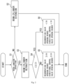
Fig. 2 is a flowchart illustrating the steps of a boom cylinder extension and retraction process performed by the hydraulic drive device illustrated inFig. 1 . -
Fig. 3 is a circuit diagram illustrating the flow of a working fluid in the hydraulic drive device illustrated inFig. 1 , when a boom cylinder is extended. -
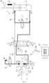
Fig. 4 is a circuit diagram illustrating the flow of a working fluid in the hydraulic drive device illustrated inFig. 1 , when a boom cylinder is retracted. -
Fig. 5 is a circuit diagram illustrating the configuration of a hydraulic drive device according toEmbodiment 2 of the present disclosure. - Hereinafter,
hydraulic drive devices Embodiments hydraulic drive devices - The
hydraulic drive device 1 illustrated inFig. 1 is included, for example, in a work vehicle (not illustrated in the drawings). Examples of the work vehicle include construction vehicles such as hydraulic excavators and hydraulic cranes and industrial vehicles such as forklifts. In the present embodiment, the work vehicle is a hydraulic excavator. The hydraulic excavator includes a boom, an arm, and an attachment (for example, a bucket). The hydraulic excavator can perform various tasks by moving the boom, the arm, and the attachment (for example, the bucket). The hydraulic excavator includes aboom cylinder 2. - The
boom cylinder 2, which is one example of the hydraulic cylinder, includes a head-end port 2a and a rod-end port 2b. Theboom cylinder 2 is provided on the boom. Theboom cylinder 2 is extended and retracted to move the boom. Theboom cylinder 2 is driven when the working fluid (for example, liquid such as oil or water) is supplied and drained to and from each of the head-end port 2a and the rod-end port 2b. More specifically, theboom cylinder 2 is extended when the working fluid is supplied to the head-end port 2a and drained from the rod-end port 2b. As a result, the boom moves upward. On the other hand, theboom cylinder 2 is retracted when the working fluid is drained from the head-end port 2a and supplied to the rod-end port 2b. As a result, the boom moves downward. Note that theboom cylinder 2 is under the empty weight of the boom in a retracting direction in the present embodiment. Therefore, theboom cylinder 2 under the empty weight of the boom causes the working fluid to be drained from the head-end port 2a and draws in the working fluid through the rod-end port 2b; thus, theboom cylinder 2 is retracted. - The
hydraulic drive device 1 supplies and drains the working fluid to and from each of the head-end port 2a and the rod-end port 2b. Thus, thehydraulic drive device 1 drives theboom cylinder 2, specifically, extends and retracts theboom cylinder 2. Furthermore, thehydraulic drive device 1 regenerates energy using the working fluid that is drained from the head-end port 2a of theboom cylinder 2. Thehydraulic drive device 1 that functions as just described includes ahydraulic pump motor 11, anelectric motor 12, adirectional control valve 13, aregeneration valve 14, and anunloader valve 15. Furthermore, thehydraulic drive device 1 includes anoperation device 16, a suction-end pressure sensor 17, astroke sensor 18, and acontrol device 19. - The
hydraulic pump motor 11 includes asuction port 11a and adischarge port 11b. Thehydraulic pump motor 11 further includes ashaft 11c. Thesuction port 11a is connected to atank 20 via asuction passage 21. Note that acheck valve 24 is interposed in thesuction passage 21. Thecheck valve 24 allows the flow of the working fluid from thetank 20 to thesuction port 11a and blocks the opposite flow of the working fluid. - When the
shaft 11c is rotatably driven, thehydraulic pump motor 11 operates as follows. Specifically, thehydraulic pump motor 11 draws in the working fluid through thesuction port 11a. Furthermore, the firsthydraulic pump motor 11 discharges the working fluid from thedischarge port 11b. On the other hand, when the working fluid is supplied to thesuction port 11a, thehydraulic pump motor 11 causes rotation of theshaft 11c. Subsequently, thehydraulic pump motor 11 discharges the working fluid from thedischarge port 11b. In the present embodiment, thehydraulic pump motor 11, which is a swash plate pump of the variable capacity type, includes aregulator 11d. Theregulator 11d changes the tilt angle of the swash plate on the basis of a capacity command that is input to theregulator 11d. As a result, the pump capacity of thehydraulic pump motor 11 changes. This means that thehydraulic pump motor 11 can change a discharge flow rate and a suction flow rate. - The
electric motor 12 is connected to thehydraulic pump motor 11. More specifically, theelectric motor 12 is coupled to theshaft 11c. Theelectric motor 12 rotatably drives thehydraulic pump motor 11 to discharge the working fluid from thehydraulic pump motor 11. More specifically, theelectric motor 12 rotatably drives theshaft 11c to discharge the working fluid from thedischarge port 11b. Furthermore, theelectric motor 12 generates electric power by rotation of the hydraulic pump motor 11 (more specifically, theshaft 11c) when supplied with the working fluid. In other words, theelectric motor 12 works with thehydraulic pump motor 11 to regenerate the fluid energy of the working fluid as electrical energy. Moreover, theelectric motor 12 changes the rotational speed (more specifically, the rotational speed of theshaft 11c) according to a rotational speed command that is input to theelectric motor 12. - The
directional control valve 13 switches the direction of the working fluid flowing between thehydraulic pump motor 11 and the head-end port 2a. Thedirectional control valve 13 is connected to each of thesuction port 11a and thedischarge port 11b of thehydraulic pump motor 11. More specifically, thedirectional control valve 13 is connected on the side of thesuction port 11a of thehydraulic pump motor 11 with respect to thecheck valve 24 in thesuction passage 21. Furthermore, thedirectional control valve 13 is connected to thedischarge port 11b via adischarge passage 22. Furthermore, thedirectional control valve 13 is connected to the head-end port 2a of theboom cylinder 2. Moreover, thedirectional control valve 13 is connected to the rod-end port 2b of theboom cylinder 2 and thetank 20. - The
directional control valve 13 switches the connection target of the head-end port 2a between thedischarge port 11b and thesuction port 11a according to an operation command that is input to thedirectional control valve 13. Furthermore, when connecting the head-end port 2a to thedischarge port 11b, thedirectional control valve 13 connects the rod-end port 2b to thetank 20. On the other hand, when connecting the head-end port 2a to thesuction port 11a, thedirectional control valve 13 connects the rod-end port 2b to thedischarge port 11b. Note that when connecting the rod-end port 2b to thedischarge port 11b, thedirectional control valve 13 allows the flow of the working fluid from thedischarge port 11b to the rod-end port 2b and blocks the opposite flow of the working fluid. Furthermore, when connecting the head-end port 2a to thesuction port 11a, thedirectional control valve 13 controls the opening degree between the head-end port 2a and thesuction port 11a (hereinafter also referred to as "the opening degree of thedirectional control valve 13") according to the operation command. In the present embodiment, thedirectional control valve 13 is an electric spool valve. Note that thedirectional control valve 13 is not limited to the electric spool valve. - The
regeneration valve 14 opens and closes aregeneration passage 23 connecting the head-end port 2a and the rod-end port 2b. Theregeneration valve 14 is interposed in theregeneration passage 23. Theregeneration valve 14 opens and closes theregeneration passage 23 according to a regeneration command. Furthermore, with theregeneration passage 23 open, theregeneration valve 14 allows the flow of the working fluid in a regeneration direction and blocks the opposite flow of the working fluid. The regeneration direction refers to the direction of the flow from the head-end port 2a to the rod-end port 2b. Thus, thesecond regeneration valve 14 regenerates, to the rod-end port 2b, the working fluid drained from the head-end port 2a. Theregeneration valve 14 reduces the opening degree according to the regeneration command. Theregeneration valve 14 is an electromagnetic proportional control valve, for example. - The
unloader valve 15 connects, to thetank 20, thedischarge passage 22 connecting thedischarge port 11b and thedirectional control valve 13. More specifically, theunloader valve 15 connects thedischarge passage 22 to thetank 20 according to an unloading command that is input to theunloader valve 15. Thus, thehydraulic pump motor 11 can be unloaded. In the present embodiment, theunloader valve 15 is a solenoid on-off valve. Note that theunloader valve 15 may be an electromagnetic proportional control valve having a controllable opening degree. - The
operation device 16 is for operating the boom (more specifically, the boom cylinder 2). Theoperation device 16 includes anoperation lever 16a. Theoperation lever 16a is configured to be operable. Theoperation device 16 outputs an operation signal corresponding to an operation direction and an operation amount of theoperation lever 16a. Theoperation device 16 is an electric joystick, for example. Note that theoperation device 16 may be a pilot operation valve. In this case, theoperation device 16 outputs an operation signal corresponding to the output pressure of the pilot operation valve. Alternatively, theoperation device 16 may be a touch panel. In this case, theoperation device 16 outputs an operation signal according to an operation that is input thereto, a program, or the like. - The suction-
end pressure sensor 17 measures inflow pressure at thehydraulic pump motor 11. The inflow pressure, which is also referred to as suction pressure, is the pressure of the working fluid flowing into thesuction port 11a of thehydraulic pump motor 11. More specifically, the suction-end pressure sensor 17 is connected to thesuction passage 21. The suction-end pressure sensor 17 measures the hydraulic pressure in thesuction passage 21 as the inflow pressure. Subsequently, the suction-end pressure sensor 17 outputs the measured inflow pressure. - The
stroke sensor 18, which is one example of the speed-related sensor, is a sensor for measuring the speed of theboom cylinder 2. More specifically, thestroke sensor 18 measures the stroke length of theboom cylinder 2. Subsequently, thestroke sensor 18 outputs the measured stroke length. Note that the speed-related sensor may be a speed sensor, an acceleration sensor, an angle sensor, and an inertial measurement unit (abbreviated as IMU); it is sufficient that the speed-related sensor be a sensor capable of calculating the speed of theboom cylinder 2 on the basis of other measurement results. Note that the speed sensor measures the speed of the stroke of theboom cylinder 2. The acceleration sensor measures the acceleration of the stroke of theboom cylinder 2. The angle sensor measures the angle of the boom. The IMU measures the acceleration and the rotational speed of the boom. - The
control device 19 controls the operation of each of thedirectional control valve 13, theregeneration valve 14, and theunloader valve 15 according to the operation signal that is input to thecontrol device 19. More specifically, thecontrol device 19 outputs the operation command, the regeneration command, and the unloading command each of which corresponds to the operation signal, thereby controlling the operations of thedirectional control valve 13, theregeneration valve 14, and theunloader valve 15. Thus, thecontrol device 19 controls the flow of the working fluid in thehydraulic drive device 1. Furthermore, thecontrol device 19 controls the operation of each of thehydraulic pump motor 11 and theelectric motor 12 according to the operation signal. More specifically, thecontrol device 19 outputs the capacity command and the rotational speed command each of which corresponds to the operation signal, thereby controlling the operations of thehydraulic pump motor 11 and theelectric motor 12. Thus, thecontrol device 19 controls the discharge flow rate and the suction flow rate at thehydraulic pump motor 11. - Furthermore, the
control device 19 changes the discharge flow rate and the suction flow rate at thehydraulic pump motor 11 according to the measurement result of thestroke sensor 18 in the present embodiment. Thus, thecontrol device 19 performs the feedback control of the speed or the acceleration (in the present embodiment, the speed) of theboom cylinder 2. Furthermore, thecontrol device 19 controls the operations of thedirectional control valve 13 and theregeneration valve 14 according to the inflow pressure measured by the suction-end pressure sensor 17. More specifically, thecontrol device 19 controls the opening degree of each of thedirectional control valve 13 and theregeneration valve 14 according to the inflow pressure measured by the suction-end pressure sensor 17. - In the
hydraulic drive device 1, when theoperation device 16 is operated (in the present embodiment, when theoperation lever 16a is operated), theoperation device 16 outputs the operation signal. Thecontrol device 19 controls the operation of each of thedirectional control valve 13, theregeneration valve 14, and theunloader valve 15 according to the operation signal. Furthermore, thecontrol device 19 controls the operation of each of theelectric motor 12 and thehydraulic pump motor 11 according to the operation signal and the measurement result of thestroke sensor 18. Thus, thecontrol device 19 extends and retracts theboom cylinder 2 in a direction and at a speed that correspond to the operation signal (in the present embodiment, the operation direction and the operation amount of theoperation lever 16a). In thehydraulic drive device 1, when lowering the boom (in other words, when retracting the boom cylinder 2), part of the working fluid drained from the head-end port 2a of theboom cylinder 2 is regenerated to the rod-end port 2b of theboom cylinder 2. Furthermore, in thehydraulic drive device 1, the remaining part of the working fluid drained from the head-end port 2a is used for energy regeneration. Moreover, thecontrol device 19 controls the opening degree of each of thedirectional control valve 13 and theregeneration valve 14 according to the inflow pressure at thehydraulic pump motor 11. This prevents an excessive increase in the load on theelectric motor 12. - Hereinafter, a boom cylinder extension and retraction process in which the
boom cylinder 2 is extended and retracted will be described in a greater detail with reference to the flowchart illustrated inFig. 2 . In thehydraulic drive device 1, when theoperation device 16 is operated in order to extend and retract theboom cylinder 2, theoperation device 16 outputs the operation signal. Thus, the boom cylinder extension and retraction process starts, and the processing transitions to Step S1. In Step S1, which is a boom lowering operation determination step, thecontrol device 19 determines whether the operation performed on theoperation device 16 is a boom lowering operation (that is, an operation to retract the boom cylinder 2). More specifically, thecontrol device 19 detects an operation direction of theoperation lever 16a on the basis of the operation signal. Subsequently, according to the operation direction of theoperation lever 16a, thecontrol device 19 determines whether the operation performed is the boom lowering operation. For example, when theoperation lever 16a is operated in a first direction, thecontrol device 19 determines that the operation performed is a boom raising operation. As a result, the processing transitions to Step S2. On the other hand, when theoperation lever 16a is operated in a second direction, thecontrol device 19 determines that the operation performed is a boom lowering operation. As a result, the processing transitions to Step S3. - In Step S2, which is a boom cylinder extension step, the
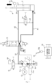
control device 19 extends theboom cylinder 2. More specifically, thecontrol device 19 operates thedirectional control valve 13 according to the operation signal. For example, thecontrol device 19 outputs the operation command corresponding to the operation signal to thedirectional control valve 13. Accordingly, thedirectional control valve 13 connects thedischarge port 11b to the head-end port 2a and connects the rod-end port 2b to thetank 20, as illustrated inFig. 3 . Note that in thedirectional control valve 13, the opening degree between thedischarge port 11b and the head-end port 2a is a full opening degree in the present embodiment. Meanwhile, thedirectional control valve 13 cuts off thesuction port 11a from the head-end port 2a and the rod-end port 2b. Furthermore, thecontrol device 19 outputs the rotational speed command and the capacity command that correspond to the operation signal. As a result, thehydraulic pump motor 11 discharges the working fluid from thedischarge port 11b at a flow rate corresponding to the operation signal. The working fluid discharged is brought to the head-end port 2a via the directional control valve 13 (the arrow A1 inFig. 3 ). Meanwhile, the working fluid is drained from the rod-end port 2b to thetank 20 via the directional control valve 13 (the arrow A2 inFig. 3 ). As a result, theboom cylinder 2 is extended at a speed corresponding to the operation signal (refer to the arrow A and the dash-dot-dot line inFig. 3 ). Thus, the boom can be raised at a speed corresponding to the operation signal. Subsequently, when the boom raising operation ends, thecontrol device 19 ends the boom cylinder extraction and retraction process. - In Step S3, which is a boom cylinder retraction step, the
control device 19 retracts theboom cylinder 2. More specifically, thecontrol device 19 operates thedirectional control valve 13, theregeneration valve 14, and theunloader valve 15 according to the operation signal. For example, thecontrol device 19 outputs the operation command corresponding to the operation signal to thedirectional control valve 13. Accordingly, thecontrol device 19 causes thedirectional control valve 13 to connect the head-end port 2a to thesuction port 11a, as illustrated inFig. 4 . Furthermore, thecontrol device 19 outputs the regeneration command to theregeneration valve 14. Accordingly, thecontrol device 19 causes theregeneration valve 14 to open theregeneration passage 23. As a result, the head-end port 2a and the rod-end port 2b are placed in communication. Moreover, thecontrol device 19 outputs the unloading command to theunloader valve 15. Accordingly, thecontrol device 19 causes theunloader valve 15 to connect thedischarge passage 22 to thetank 20. As a result, thehydraulic pump motor 11 is unloaded. - When the
directional control valve 13, theregeneration valve 14, and theunloader valve 15 are operated as described above, the working fluid flows as follows. Specifically, theboom cylinder 2 is under the empty weight of the boom in the retracting direction. Therefore, theboom cylinder 2 is retracted under the empty weight of the boom. Thus, the working fluid is drained from the head-end port 2a. Part of the working fluid drained is supplied to the rod-end port 2b through theregeneration passage 23. In other words, part of the working fluid is regenerated from the head-end port 2a to the rod-end port 2b (refer to the arrow B1 inFig. 4 ). Meanwhile, the remaining part is supplied to thesuction port 11a of thehydraulic pump motor 11 via the directional control valve 13 (refer to the arrow B2 inFig. 4 ). Subsequently, the remaining part rotatably drives theelectric motor 12 via thehydraulic pump motor 11 and then is drained from thedischarge port 11b to thetank 20 via theunloader valve 15. When theelectric motor 12 is rotatably driven, theelectric motor 12 generates electric power. As a result, the fluid energy of the remaining part is regenerated as electrical energy. In other words, the potential energy of the boom is regenerated as electrical energy. Thus, energy can be regenerated using the working fluid drained. - Furthermore, by controlling the suction flow rate at the
hydraulic pump motor 11, thecontrol device 19 retracts theboom cylinder 2 at a speed corresponding to the operation signal. More specifically, thecontrol device 19 outputs the rotational speed command and the capacity command that correspond to the operation signal. Accordingly, thehydraulic pump motor 11 can cause the working fluid to flow into thesuction port 11a at a flow rate corresponding to the operation signal; thus, the flow rate of the working fluid that is drained from the head-end port 2a of theboom cylinder 2 can be controlled and set to the flow rate corresponding to the operation signal. As a result, the flow rate of the working fluid that is regenerated to the rod-end port 2b can be controlled and set to the flow rate corresponding to the operation signal and therefore, theboom cylinder 2 can be retracted at a speed corresponding to the operation signal (refer to the arrow B and the dash-dot-dot line inFig. 4 ). Thus, the boom can be lowered at a speed corresponding to the operation signal. When theboom cylinder 2 is retracted according to the boom lowering operation, the processing proceeds to Step S4. - Note that the
control device 19 performs the following feedback control in the boom lowering operation. Specifically, thecontrol device 19 changes the suction flow rate at thehydraulic pump motor 11 according to the measurement result of thestroke sensor 18. More specifically, thecontrol device 19 changes the suction flow rate at thehydraulic pump motor 11 by outputting the capacity command and the rotational speed command according to the measurement result of thestroke sensor 18. In this manner, thecontrol device 19 performs the feedback control of the speed of theboom cylinder 2. This leads to a reduced occurrence of hunting in theboom cylinder 2. - In Step S4, which is an inflow load determination step, the
control device 19 determines whether an inflow load that is a load flowing to theelectric motor 12 is greater than or equal to a predetermined value I1. More specifically, thecontrol device 19 estimates an inflow load I on the basis of the inflow pressure measured by the suction-end pressure sensor 17. To be specific, thecontrol device 19 calculates the suction flow rate at thehydraulic pump motor 11 on the basis of the rotational speed command and the capacity command. Subsequently, thecontrol device 19 estimates the inflow load I on the basis of the suction flow rate and the inflow pressure. Thecontrol device 19 determines whether the inflow load I is greater than or equal to the predetermined value I1. When the inflow load I is less than the predetermined value I1, the processing proceeds to Step S5. On the other hand, when the inflow load I is greater than or equal to the predetermined value I1, the processing proceeds to Step S6. - In Step S5, which is a first opening degree control step, the
control device 19 controls the opening degree of theregeneration valve 14 according to the inflow load I. More specifically, thecontrol device 19 sets an opening degree R of theregeneration valve 14 to at least a predetermined first regeneration opening degree R1, for example, a full opening degree. Furthermore, thecontrol device 19 sets the opening degree between the head-end port 2a and thesuction port 11a, that is, an opening degree D of thedirectional control valve 13, to at least a predetermined first regeneration opening degree D1, for example, a full opening degree. By placing theregeneration valve 14 and thedirectional control valve 13 in fully open states in this manner, it is possible to minimize the occurrence of pressure losses in the working fluid, meaning that more energy can be regenerated as electrical energy. Note that each of the first regeneration opening degree R1 and the first regeneration opening degree D1 does not necessarily need to be the full opening degree; it is sufficient that each of the first regeneration opening degree R1 and the first regeneration opening degree D1 be at least 85% of the full opening degree. Subsequently, when the boom lowering operation ends, thecontrol device 19 ends the boom cylinder extraction and retraction process. - In Step S6, which is a second opening degree control step, the
control device 19 reduces the opening degree of theregeneration valve 14. More specifically, thecontrol device 19 reduces the opening degree R of theregeneration valve 14 from the first regeneration opening degree R1. In other words, thecontrol device 19 reduces the opening degree R of theregeneration valve 14 to a second regeneration opening degree R2 (an opening degree that is, for example, 20% or more and less than 85% of the opening degree in the fully open state). As a result, a pressure loss occurs in the working fluid flowing in thehydraulic drive device 1. Therefore, the fluid energy of the working fluid to be supplied to thehydraulic pump motor 11 can be reduced. Note that the second regeneration opening degree R2 is not limited to the aforementioned numerical range; it is sufficient that the second regeneration opening degree R2 be less than the first regeneration opening degree R1. - Furthermore, the
control device 19 reduces the opening degree of thedirectional control valve 13. More specifically, thecontrol device 19 reduces the opening degree D of thedirectional control valve 13 from the first regeneration opening degree D1. In other words, thecontrol device 19 reduces the opening degree D of thedirectional control valve 13 to a second regeneration opening degree D2 (an opening degree that is, for example, 20% or more and less than 85% of the opening degree in the fully open state). As a result, it is possible to cause a pressure loss in the working fluid to be supplied to thehydraulic pump motor 11 while minimizing the reduction in the hydraulic pressure of the working fluid to be supplied to the rod-end port 2b. Therefore, the fluid energy of the working fluid to be supplied to thehydraulic pump motor 11 can be reduced. Note that the second regeneration opening degree D2 is not limited to the aforementioned numerical range; it is sufficient that the second regeneration opening degree D2 be less than the first regeneration opening degree D1. - In this manner, in the
hydraulic drive device 1, the fluid energy of the working fluid is reduced using theregeneration valve 14 and thedirectional control valve 13. As a result, the fluid energy flowing into thehydraulic pump motor 11 is reduced. Therefore, the inflow load on theelectric motor 12 is reduced during regeneration. After the opening degrees of theregeneration valve 14 and thedirectional control valve 13 are reduced, thecontrol device 19 ends the boom cylinder extraction and retraction process when the boom lowering operation ends. - Note that the
control device 19 controls the pump capacity of thehydraulic pump motor 11 and the rotational speed of theelectric motor 12 according to the inflow load during regeneration. More specifically, according to the estimated inflow load, thecontrol device 19 limits the capacity command and the rotational speed command to be output. Thus, each of the pump capacity of thehydraulic pump motor 11 and the rotational speed of theelectric motor 12 is limited. As a result, the suction flow rate at thehydraulic pump motor 11 can be reduced. This allows for a reduction in the amount of energy to be regenerated using theelectric motor 12 during regeneration. Accordingly, it is possible to reduce the occurrence of an excessive load (for example, output exceeding the rated output) acting on theelectric motor 12. - In the
hydraulic drive device 1 according to the present embodiment, the opening degree of theregeneration valve 14 is controlled according to the inflow pressure. Therefore, it is possible to cause a pressure loss by theregeneration valve 14 when an excessive load acts on theelectric motor 12 during regeneration. Thus, the occurrence of an excessive load acting on theelectric motor 12 is reduced during regeneration. - Furthermore, in the
hydraulic drive device 1 according to the present embodiment, when the inflow load is greater than or equal to a predetermined value, thecontrol device 19 reduces the opening degree of theregeneration valve 14. Therefore, it is possible to cause a pressure loss. This allows for a reduction in the load on theelectric motor 12 during regeneration. Therefore, theelectric motor 12 can be kept from being overloaded. On the other hand, when the inflow load is less than the predetermined value, the opening degree of theregeneration valve 14 remains large, making it possible to reduce the pressure loss during regeneration. Thus, the regeneration efficiency in thehydraulic drive device 1 can be maintained at a high level. - Furthermore, in the
hydraulic drive device 1 according to the present embodiment, when the inflow load is greater than or equal to a predetermined value, thecontrol device 19 reduces the opening degree of thedirectional control valve 13. Therefore, it is possible to cause a pressure loss. This allows for a reduction in the load on theelectric motor 12 during regeneration. Therefore, theelectric motor 12 can be kept from being overloaded. On the other hand, when the inflow load is less than the predetermined value, the opening degree of thedirectional control valve 13 remains large, making it possible to reduce the pressure loss during regeneration. Thus, the regeneration efficiency in thehydraulic drive device 1 can be maintained at a high level. - Furthermore, in the
hydraulic drive device 1 according to the present embodiment, thecontrol device 19 controls the rotational speed of theelectric motor 12 according to the inflow pressure. Therefore, it is possible to reduce the suction flow rate at thehydraulic pump motor 11 by reducing the rotational speed of theelectric motor 12. This allows for a reduction in the load on theelectric motor 12. Therefore, theelectric motor 12 is kept from being overloaded. - Furthermore, in the
hydraulic drive device 1 according to the present embodiment, thecontrol device 19 controls the pump capacity of thehydraulic pump motor 11 according to the inflow pressure. Therefore, it is possible to reduce the suction flow rate at thehydraulic pump motor 11 by reducing the pump capacity of thehydraulic pump motor 11. This allows for a reduction in the load on theelectric motor 12. Therefore, theelectric motor 12 is kept from being overloaded. - Furthermore, in the
hydraulic drive device 1 according to the present embodiment, theunloader valve 15 connects thedischarge passage 22 to thetank 20 when energy is regenerated using theelectric motor 12. This makes it possible to reduce the increase in discharge pressure at thehydraulic pump motor 11. Therefore, the regeneration efficiency in theelectric motor 12 can be maintained at a high level. - A
hydraulic drive device 1A according toEmbodiment 2 is similar in configuration to thehydraulic drive device 1 according toEmbodiment 1. Therefore, the configuration of thehydraulic drive device 1A according toEmbodiment 2 will be described focusing on differences from thehydraulic drive device 1 according toEmbodiment 1; elements that are the same as those of thehydraulic drive device 1 according toEmbodiment 1 share the same reference signs, and as such, description of the elements will be omitted. - The
hydraulic drive device 1A according toEmbodiment 2, which is illustrated inFig. 5 , includes ahydraulic pump motor 11A, theelectric motor 12, adirectional control valve 13A, and theregeneration valve 14. Furthermore, thehydraulic drive device 1A includes theoperation device 16, apressure sensor 17A, thestroke sensor 18, and acontrol device 19A. - The
hydraulic pump motor 11A includes a first port 11Aa, a second port 11Ab, and theshaft 11c. The first port 11Aa is connected to thetank 20 via atank passage 21A. The second port 11Ab is connected to apump passage 22A. When theshaft 11c is rotatably driven forward, thehydraulic pump motor 11A draws in the working fluid through the first port 11Aa and discharges the working fluid from the second port 11Ab. On the other hand, when the working fluid is supplied to the second port 11Ab, thehydraulic pump motor 11A rotates theshaft 11c backward. Subsequently, thehydraulic pump motor 11A drains the working fluid from the first port 11Aa. In the present embodiment, thehydraulic pump motor 11A, which is a swash plate pump of the variable capacity type, includes theregulator 11d. - The
directional control valve 13A switches the direction of the working fluid flowing between thehydraulic pump motor 11A and the head-end port 2a. Thedirectional control valve 13A is connected to the second port 11Ab of thehydraulic pump motor 11A via thepump passage 22A. Furthermore, thedirectional control valve 13A is connected to the head-end port 2a and the rod-end port 2b of theboom cylinder 2. Moreover, thedirectional control valve 13A is connected to thetank 20. - When the operation command is input to the
directional control valve 13A, thedirectional control valve 13A connects the second port 11Ab to the head-end port 2a. Furthermore, thedirectional control valve 13A opens and closes the path between the rod-end port 2b and thetank 20 according to the operation command that is input to thedirectional control valve 13A. Thus, thedirectional control valve 13A can switch the direction of the working fluid flowing between thehydraulic pump motor 11A and the head-end port 2a. When causing the working fluid to flow from the head-end port 2a to the second port 11Ab, thedirectional control valve 13A controls the opening degree between the head-end port 2a and the second port 11Ab (that is, the opening degree of thedirectional control valve 13A) according to the operation command. In the present embodiment, thedirectional control valve 13A is an electric spool valve. Note that thedirectional control valve 13A is not limited to the electric spool valve. - The
pressure sensor 17A measures inflow pressure at thehydraulic pump motor 11A. More specifically, thepressure sensor 17A is connected to thepump passage 22A. Thepressure sensor 17A measures the hydraulic pressure of the working fluid flowing through thepump passage 22A. Therefore, thepressure sensor 17A measures, as inflow pressure, the hydraulic pressure of the working fluid flowing through thepump passage 22A during regeneration. Thepressure sensor 17A outputs the measured inflow pressure. - The
control device 19A controls the operation of each of thedirectional control valve 13A, theregeneration valve 14, and theunloader valve 15 according to an operation signal that is input to thecontrol device 19A, as with thecontrol device 19 according toEmbodiment 1. Furthermore, thecontrol device 19A changes the discharge flow rate and the suction flow rate at thehydraulic pump motor 11A according to the measurement result of thestroke sensor 18 in the present embodiment. Furthermore, thecontrol device 19A controls the opening degree of each of thedirectional control valve 13A and theregeneration valve 14 according to the inflow pressure measured by thepressure sensor 17A. - In the
hydraulic drive device 1A, when theoperation device 16 is operated (in the present embodiment, when theoperation lever 16a is operated), the boom cylinder extension and retraction process is performed as in thehydraulic drive device 1 according toEmbodiment 1. The boom cylinder extension and retraction process performed by thecontrol device 19A is similar to the boom cylinder extension and retraction process performed by thecontrol device 19 according toEmbodiment 1. Hereinafter, the boom cylinder extension and retraction process performed by thecontrol device 19A will be described focusing on differences from the boom cylinder extension and retraction process performed by thecontrol device 19 according toEmbodiment 1. - In Step S2, which is the boom cylinder extension step, the
control device 19A extends theboom cylinder 2. More specifically, thecontrol device 19A operates thedirectional control valve 13A according to the operation signal. For example, thecontrol device 19A outputs the operation command corresponding to the operation signal to thedirectional control valve 13A. Accordingly, thedirectional control valve 13A connects the second port 11Ab to the head-end port 2a and connects the rod-end port 2b to thetank 20. Furthermore, thecontrol device 19A outputs the rotational speed command and the capacity command that correspond to the operation signal. As a result, thehydraulic pump motor 11A discharges the working fluid from the second port 11Ab at a flow rate corresponding to the operation signal. Thus, the boom can be raised at a speed corresponding to the operation signal. Subsequently, when the boom raising operation ends, thecontrol device 19A ends the boom cylinder extraction and retraction process. - In Step S3, which is the boom cylinder retraction step, the
control device 19A retracts theboom cylinder 2. More specifically, thecontrol device 19A operates thedirectional control valve 13A and theregeneration valve 14 according to the operation signal. For example, thecontrol device 19A outputs the operation command corresponding to the operation signal to thedirectional control valve 13A. Thus, thecontrol device 19A causes thedirectional control valve 13A to connect the head-end port 2a to the second port 11Ab and cuts off the path between the rod-end port 2b and thetank 20. Furthermore, thecontrol device 19A outputs the regeneration command to theregeneration valve 14, causing theregeneration valve 14 to open theregeneration passage 23. As a result, in theboom cylinder 2 under the empty weight of the boom in the retracting direction, the working fluid is pushed out through the head-end port 2a. Part of the working fluid pushed out is regenerated to the rod-end port 2b. The remaining part is brought to thehydraulic pump motor 11A. Subsequently, energy is regenerated in theelectric motor 12. Furthermore, similar to thecontrol device 19 according toEmbodiment 1, thecontrol device 19A controls the suction flow rate to retract theboom cylinder 2 at a speed corresponding to the operation signal, and performs the feedback control of the speed or the acceleration of theboom cylinder 2 according to the measurement result of thestroke sensor 18. When theboom cylinder 2 is retracted according to the boom lowering operation in this manner, the processing transitions to Step S4. - In Step S4, which is an inflow load determination step, the
control device 19A estimates the inflow load I on the basis of the inflow pressure measured by thepressure sensor 17A. To be specific, thecontrol device 19A calculates the suction flow rate at thehydraulic pump motor 11A on the basis of the rotational speed command and the capacity command. Subsequently, thecontrol device 19A estimates the inflow load I on the basis of the suction flow rate and the inflow pressure. When the estimated inflow load I is less than the predetermined value I1, the processing proceeds to Step S5. On the other hand, when the inflow load I is greater than or equal to the predetermined value I1, the processing proceeds to Step S6. - The
hydraulic drive device 1A according to the present embodiment produces substantially the same advantageous effects as those produced by thehydraulic drive device 1 according toEmbodiment 1. - In the
hydraulic drive devices boom cylinder 2 such as an arm cylinder and a lift cylinder, for example. Thedirectional control valves regeneration valve 14 do not necessarily need to both have adjustable opening degrees; it is sufficient that at least one of thedirectional control valves regeneration valve 14 be configured so that the opening degree thereof can be adjusted. When the inflow load increases, thecontrol devices directional control valves regeneration valve 14. It is sufficient that thecontrol devices directional control valves regeneration valve 14. Furthermore, thecontrol devices directional control valves regeneration valve 14 according to the inflow load. For example, according to an increase in the inflow load, thecontrol devices regeneration valve 14, and then reduce the opening degrees of thedirectional control valves control devices hydraulic pump motors electric motor 12. Moreover, thecontrol devices boom cylinder 2. In addition, the drive source for thehydraulic pump motors electric motor 12 and may be a hybrid drive source that uses theelectric motor 12 and an engine. - A hydraulic drive device according to the first aspect drives a hydraulic cylinder by supplying and draining a working fluid to and from each of a head-end port and a rod-end port of the hydraulic cylinder and includes: a hydraulic pump motor that discharges the working fluid and is rotatably driven by the working fluid; an electric motor connected to the hydraulic pump motor; a directional control valve that switches a direction of the working fluid flowing between the hydraulic pump motor and the head-end port; a regeneration valve that opens and closes a regeneration passage connecting the head-end port and the rod-end port; a pressure sensor that measures inflow pressure at the hydraulic pump motor; and a control device that controls an operation of each of the directional control valve and the regeneration valve. When causing the regeneration valve to open the regeneration passage and causing the directional control valve to connect the head-end port and the hydraulic pump motor, the control device controls an opening degree of the regeneration valve according to the inflow pressure of the working fluid that is measured by the pressure sensor.
- According to this aspect, the opening degree of the regeneration valve is controlled according to the inflow pressure. Therefore, it is possible to cause a pressure loss by the regeneration valve when an excessive load acts on the electric motor during regeneration. Thus, the occurrence of an excessive load acting on the electric motor is reduced during regeneration.
- As a hydraulic drive device according to the second aspect, in the hydraulic drive device according to the first aspect, when an inflow load calculated according to the inflow pressure measured by the pressure sensor and a rotational speed of the electric motor is greater than or equal to a predetermined value, the control device may reduce the opening degree of the regeneration valve.
- According to this aspect, when the inflow load is greater than or equal to the predetermined value, the control device reduces the opening degree of the regeneration valve. Therefore, it is possible to cause a pressure loss. This allows for a reduction in the load on the electric motor during regeneration. Therefore, the electric motor can be kept from being overloaded. On the other hand, when the inflow load is less than the predetermined value, the opening degree of the regeneration valve remains large, making it possible to reduce the pressure loss during regeneration. Thus, the regeneration efficiency in the hydraulic drive device can be maintained at a high level.
- As a hydraulic drive device according to the third aspect, in the hydraulic drive device according to the first or second aspect, when an inflow load calculated according to the inflow pressure measured by the pressure sensor and a rotational speed of the electric motor is greater than or equal to a predetermined value, the control device may cause the directional control valve to reduce an opening degree between the head-end port and the hydraulic pump motor.
- According to this aspect, when the inflow load is greater than or equal to the predetermined value, the control device reduces the opening degree of the directional control valve. Therefore, it is possible to cause a pressure loss. This allows for a reduction in the load on the electric motor during regeneration. Therefore, the electric motor can be kept from being overloaded. On the other hand, when the inflow load is less than the predetermined value, the opening degree of the directional control valve remains large, making it possible to reduce the pressure loss during regeneration. Thus, the regeneration efficiency in the hydraulic drive device can be maintained at a high level.
- As a hydraulic drive device according to the fourth aspect, in the hydraulic drive device according to any one of the first to third aspects, the control device may control a rotational speed of the electric motor according to the inflow pressure measured by the pressure sensor.
- According to this aspect, the control device controls the rotational speed of the electric motor according to the inflow pressure. Therefore, it is possible to reduce the suction flow rate at the hydraulic pump motor by reducing the rotational speed of the electric motor. This allows for a reduction in the load on the electric motor. Therefore, the electric motor is kept from being overloaded.
- As a hydraulic drive device according to the fifth aspect, in the hydraulic drive device according to any one of the first to fourth aspects, a pump capacity of the hydraulic pump motor may be changeable, and the control device may control the pump capacity of the hydraulic pump motor according to the inflow pressure measured by the pressure sensor.
- According to this aspect, the control device controls the pump capacity of the hydraulic pump motor according to the inflow pressure. Therefore, it is possible to reduce the suction flow rate at the hydraulic pump motor by reducing the pump capacity of the hydraulic pump motor. This allows for a reduction in the load on the electric motor. Therefore, the electric motor is kept from being overloaded.
- As a hydraulic drive device according to the sixth aspect, the hydraulic drive device according to any one of the first to fifth aspects may further include an unloader valve, the hydraulic pump motor may include a discharge port through which the working fluid is discharged and a suction port through which the working fluid is drawn in, the directional control valve may switch a connection target of each of the head-end port and the rod-end port between the discharge port and the suction port, the unloader valve may connect, to a tank, a discharge passage connecting the discharge port and the directional control valve, and when causing the directional control valve to connect the head-end port to the suction port, the control device may actuate the unloader valve.
- According to this aspect, the unloader valve connects the discharge passage to the tank when energy is regenerated using the electric motor. This makes it possible to reduce the increase in discharge pressure at the hydraulic pump motor. Therefore, the regeneration efficiency in the electric motor can be maintained at a high level.
- From the foregoing description, many modifications and other embodiments of the present invention would be obvious to a person having ordinary skill in the art. Therefore, the foregoing description should be interpreted only as an example and is provided for the purpose of teaching the best mode for carrying out the present invention to a person having ordinary skill in the art. Substantial changes in details of the structures and/or functions of the present invention are possible within the spirit of the present invention.
Claims (6)
- A hydraulic drive device that drives a hydraulic cylinder by supplying and draining a working fluid to and from each of a head-end port and a rod-end port of the hydraulic cylinder, the hydraulic drive device comprising:a hydraulic pump motor that discharges the working fluid and is rotatably driven by the working fluid;an electric motor connected to the hydraulic pump motor;a directional control valve that switches a direction of the working fluid flowing between the hydraulic pump motor and the head-end port;a regeneration valve that opens and closes a regeneration passage connecting the head-end port and the rod-end port;a pressure sensor that measures inflow pressure at the hydraulic pump motor; anda control device that controls an operation of each of the directional control valve and the regeneration valve, wherein:
when causing the regeneration valve to open the regeneration passage and causing the directional control valve to connect the head-end port and the hydraulic pump motor, the control device controls an opening degree of the regeneration valve according to the inflow pressure of the working fluid that is measured by the pressure sensor. - The hydraulic drive device according to claim 1, wherein:
when an inflow load calculated according to the inflow pressure measured by the pressure sensor and a rotational speed of the electric motor is greater than or equal to a predetermined value, the control device reduces the opening degree of the regeneration valve. - The hydraulic drive device according to claim 1 or 2, wherein:
when an inflow load calculated according to the inflow pressure measured by the pressure sensor and a rotational speed of the electric motor is greater than or equal to a predetermined value, the control device causes the directional control valve to reduce an opening degree between the head-end port and the hydraulic pump motor. - The hydraulic drive device according to claim 1 or 2, wherein:
the control device controls a rotational speed of the electric motor according to the inflow pressure measured by the pressure sensor. - The hydraulic drive device according to claim 1 or 2, wherein:a pump capacity of the hydraulic pump motor is changeable; andthe control device controls the pump capacity of the hydraulic pump motor according to the inflow pressure measured by the pressure sensor.
- The hydraulic drive device according to claim 1 or 2, further comprising:
an unloader valve, wherein:the hydraulic pump motor includes a discharge port through which the working fluid is discharged and a suction port through which the working fluid is drawn in;the directional control valve switches a connection target of each of the head-end port and the rod-end port between the discharge port and the suction port;the unloader valve connects, to a tank, a discharge passage connecting the discharge port and the directional control valve; andwhen causing the directional control valve to connect the head-end port to the suction port, the control device actuates the unloader valve.
Applications Claiming Priority (2)
| Application Number | Priority Date | Filing Date | Title |
|---|---|---|---|
| JP2022101451A JP7847487B2 (en) | 2022-06-23 | 2022-06-23 | Hydraulic drive device |
| PCT/JP2023/019119 WO2023248682A1 (en) | 2022-06-23 | 2023-05-23 | Hydraulic driving device |
Publications (2)
| Publication Number | Publication Date |
|---|---|
| EP4549746A1 true EP4549746A1 (en) | 2025-05-07 |
| EP4549746A4 EP4549746A4 (en) | 2026-07-29 |
Family
ID=89379739
Family Applications (1)
| Application Number | Title | Priority Date | Filing Date |
|---|---|---|---|
| EP23826870.0A Pending EP4549746A4 (en) | 2022-06-23 | 2023-05-23 | Hydraulic driving device |
Country Status (5)
| Country | Link |
|---|---|
| US (1) | US20260022718A1 (en) |
| EP (1) | EP4549746A4 (en) |
| JP (1) | JP7847487B2 (en) |
| CN (1) | CN119630890A (en) |
| WO (1) | WO2023248682A1 (en) |
Family Cites Families (19)
| Publication number | Priority date | Publication date | Assignee | Title |
|---|---|---|---|---|
| JP3877307B2 (en) | 2002-10-18 | 2007-02-07 | 株式会社小松製作所 | Pressure oil energy recovery device |
| KR100611713B1 (en) * | 2004-10-14 | 2006-08-11 | 볼보 컨스트럭션 이키프먼트 홀딩 스웨덴 에이비 | Hydraulic control valve with regenerative function |
| SE531309C2 (en) * | 2006-01-16 | 2009-02-17 | Volvo Constr Equip Ab | Control system for a working machine and method for controlling a hydraulic cylinder of a working machine |
| JP4973087B2 (en) | 2006-09-21 | 2012-07-11 | コベルコ建機株式会社 | Control device for hydraulic work machine |
| JP2008157407A (en) | 2006-12-26 | 2008-07-10 | Hy:Kk | Hydraulic drive mechanism |
| US7634911B2 (en) * | 2007-06-29 | 2009-12-22 | Caterpillar Inc. | Energy recovery system |
| EP2329155B1 (en) * | 2008-09-11 | 2013-05-29 | Parker-Hannifin Corporation | Method of controlling an electro-hydraulic actuator system having multiple functions |
| JP5530728B2 (en) | 2010-01-20 | 2014-06-25 | 株式会社神戸製鋼所 | Hydraulic control device and hydraulic work machine equipped with the same |
| US20120055149A1 (en) * | 2010-09-02 | 2012-03-08 | Bucyrus International, Inc. | Semi-closed hydraulic systems |
| CN104903595B (en) * | 2013-01-08 | 2017-03-08 | 日立建机株式会社 | The hydraulic system of work mechanism |
| EP2947332B1 (en) * | 2013-01-17 | 2018-10-31 | Hitachi Construction Machinery Co., Ltd. | Device for recovering pressurized oil energy from work machine |
| US9394922B2 (en) * | 2013-08-29 | 2016-07-19 | Caterpillar Global Mining Llc | Hydraulic control circuit with regeneration valve |
| KR102319371B1 (en) | 2014-06-20 | 2021-11-01 | 파커-한니핀 코포레이션 | Method of controlling velocity of a hydraulic actuator in over-center linkage systems |
| WO2015198644A1 (en) * | 2014-06-26 | 2015-12-30 | 日立建機株式会社 | Work machine |
| JP6469844B2 (en) * | 2015-03-27 | 2019-02-13 | 住友重機械工業株式会社 | Excavator and excavator driving method |
| EP3669086A4 (en) * | 2017-08-16 | 2021-05-12 | Kyntronics, Inc. | Electrohydraulic actuator |
| JP7478588B2 (en) | 2020-05-18 | 2024-05-07 | 川崎重工業株式会社 | Hydraulic Excavator Drive System |
| JP7523259B2 (en) | 2020-06-19 | 2024-07-26 | 川崎重工業株式会社 | Hydraulic Drive System |
| US20220252088A1 (en) * | 2021-02-09 | 2022-08-11 | Purdue Research Foundation | Electro-hydraulic actuator systems and methods of operating the same |
-
2022
- 2022-06-23 JP JP2022101451A patent/JP7847487B2/en active Active
-
2023
- 2023-05-23 CN CN202380049090.0A patent/CN119630890A/en active Pending
- 2023-05-23 EP EP23826870.0A patent/EP4549746A4/en active Pending
- 2023-05-23 WO PCT/JP2023/019119 patent/WO2023248682A1/en not_active Ceased
- 2023-05-23 US US18/877,442 patent/US20260022718A1/en active Pending
Also Published As
| Publication number | Publication date |
|---|---|
| WO2023248682A1 (en) | 2023-12-28 |
| CN119630890A (en) | 2025-03-14 |
| JP2024002331A (en) | 2024-01-11 |
| JP7847487B2 (en) | 2026-04-17 |
| US20260022718A1 (en) | 2026-01-22 |
| EP4549746A4 (en) | 2026-07-29 |
Similar Documents
| Publication | Publication Date | Title |
|---|---|---|
| US10184225B2 (en) | Working machine | |
| CN104603468B (en) | The fluid pressure drive device of engineering machinery | |
| CN104093994B (en) | hydraulic drive system | |
| US11098462B2 (en) | Construction machine | |
| EP2681458A2 (en) | Hydraulic control system having cylinder stall strategy | |
| WO2012166225A2 (en) | Hydraulic control system having cylinder stall strategy | |
| US10767674B2 (en) | Construction machine | |
| WO2016081179A1 (en) | System having energy recovery with pilot priority | |
| EP3795843A1 (en) | Construction machine | |
| EP3722518B1 (en) | Slewing-type hydraulic work machine | |
| EP4545808A1 (en) | Hydraulic drive device | |
| EP4545802A1 (en) | Hydraulic drive device | |
| US20260022718A1 (en) | Hydraulic drive device | |
| EP4545809A1 (en) | Hydraulic drive device | |
| US20250382980A1 (en) | Hydraulic drive device | |
| CN113544389B (en) | Work machine | |
| JP2008185098A (en) | Control system in working machine | |
| JP2008185099A (en) | Control system in working machine | |
| CN116964337B (en) | Engineering machinery | |
| KR20250049552A (en) | work machine | |
| JP2026059836A (en) | Control system and control method for working machinery |
Legal Events
| Date | Code | Title | Description |
|---|---|---|---|
| STAA | Information on the status of an ep patent application or granted ep patent |
Free format text: STATUS: THE INTERNATIONAL PUBLICATION HAS BEEN MADE |
|
| PUAI | Public reference made under article 153(3) epc to a published international application that has entered the european phase |
Free format text: ORIGINAL CODE: 0009012 |
|
| STAA | Information on the status of an ep patent application or granted ep patent |
Free format text: STATUS: REQUEST FOR EXAMINATION WAS MADE |
|
| 17P | Request for examination filed |
Effective date: 20250123 |
|
| AK | Designated contracting states |
Kind code of ref document: A1 Designated state(s): AL AT BE BG CH CY CZ DE DK EE ES FI FR GB GR HR HU IE IS IT LI LT LU LV MC ME MK MT NL NO PL PT RO RS SE SI SK SM TR |
|
| DAV | Request for validation of the european patent (deleted) | ||
| DAX | Request for extension of the european patent (deleted) | ||
| A4 | Supplementary search report drawn up and despatched |
Effective date: 20260624 |
|
| RIC1 | Information provided on ipc code assigned before grant |
Ipc: F15B 11/024 20060101AFI20260623BHEP Ipc: F15B 11/00 20060101ALI20260623BHEP Ipc: F15B 21/14 20060101ALI20260623BHEP Ipc: E02F 9/22 20060101ALI20260623BHEP |