EP4549720A1 - Electronic throttle control method and electronic throttle control device - Google Patents
Electronic throttle control method and electronic throttle control device Download PDFInfo
- Publication number
- EP4549720A1 EP4549720A1 EP24204553.2A EP24204553A EP4549720A1 EP 4549720 A1 EP4549720 A1 EP 4549720A1 EP 24204553 A EP24204553 A EP 24204553A EP 4549720 A1 EP4549720 A1 EP 4549720A1
- Authority
- EP
- European Patent Office
- Prior art keywords
- engine revolution
- revolution speed
- torque
- integral
- throttle
- Prior art date
- Legal status (The legal status is an assumption and is not a legal conclusion. Google has not performed a legal analysis and makes no representation as to the accuracy of the status listed.)
- Pending
Links
Images

Classifications
-
- F—MECHANICAL ENGINEERING; LIGHTING; HEATING; WEAPONS; BLASTING
- F02—COMBUSTION ENGINES; HOT-GAS OR COMBUSTION-PRODUCT ENGINE PLANTS
- F02D—CONTROLLING COMBUSTION ENGINES
- F02D11/00—Arrangements for, or adaptations to, non-automatic engine control initiation means, e.g. operator initiated
- F02D11/06—Arrangements for, or adaptations to, non-automatic engine control initiation means, e.g. operator initiated characterised by non-mechanical control linkages, e.g. fluid control linkages or by control linkages with power drive or assistance
- F02D11/10—Arrangements for, or adaptations to, non-automatic engine control initiation means, e.g. operator initiated characterised by non-mechanical control linkages, e.g. fluid control linkages or by control linkages with power drive or assistance of the electric type
- F02D11/105—Arrangements for, or adaptations to, non-automatic engine control initiation means, e.g. operator initiated characterised by non-mechanical control linkages, e.g. fluid control linkages or by control linkages with power drive or assistance of the electric type characterised by the function converting demand to actuation, e.g. a map indicating relations between an accelerator pedal position and throttle valve opening or target engine torque
-
- F—MECHANICAL ENGINEERING; LIGHTING; HEATING; WEAPONS; BLASTING
- F02—COMBUSTION ENGINES; HOT-GAS OR COMBUSTION-PRODUCT ENGINE PLANTS
- F02D—CONTROLLING COMBUSTION ENGINES
- F02D41/00—Electrical control of supply of combustible mixture or its constituents
- F02D41/0002—Controlling intake air
-
- F—MECHANICAL ENGINEERING; LIGHTING; HEATING; WEAPONS; BLASTING
- F02—COMBUSTION ENGINES; HOT-GAS OR COMBUSTION-PRODUCT ENGINE PLANTS
- F02D—CONTROLLING COMBUSTION ENGINES
- F02D11/00—Arrangements for, or adaptations to, non-automatic engine control initiation means, e.g. operator initiated
- F02D11/06—Arrangements for, or adaptations to, non-automatic engine control initiation means, e.g. operator initiated characterised by non-mechanical control linkages, e.g. fluid control linkages or by control linkages with power drive or assistance
- F02D11/10—Arrangements for, or adaptations to, non-automatic engine control initiation means, e.g. operator initiated characterised by non-mechanical control linkages, e.g. fluid control linkages or by control linkages with power drive or assistance of the electric type
-
- F—MECHANICAL ENGINEERING; LIGHTING; HEATING; WEAPONS; BLASTING
- F02—COMBUSTION ENGINES; HOT-GAS OR COMBUSTION-PRODUCT ENGINE PLANTS
- F02D—CONTROLLING COMBUSTION ENGINES
- F02D31/00—Use of speed-sensing governors to control combustion engines, not otherwise provided for
- F02D31/001—Electric control of rotation speed
- F02D31/002—Electric control of rotation speed controlling air supply
-
- F—MECHANICAL ENGINEERING; LIGHTING; HEATING; WEAPONS; BLASTING
- F02—COMBUSTION ENGINES; HOT-GAS OR COMBUSTION-PRODUCT ENGINE PLANTS
- F02D—CONTROLLING COMBUSTION ENGINES
- F02D41/00—Electrical control of supply of combustible mixture or its constituents
- F02D41/009—Electrical control of supply of combustible mixture or its constituents using means for generating position or synchronisation signals
-
- F—MECHANICAL ENGINEERING; LIGHTING; HEATING; WEAPONS; BLASTING
- F02—COMBUSTION ENGINES; HOT-GAS OR COMBUSTION-PRODUCT ENGINE PLANTS
- F02D—CONTROLLING COMBUSTION ENGINES
- F02D41/00—Electrical control of supply of combustible mixture or its constituents
- F02D41/02—Circuit arrangements for generating control signals
- F02D41/14—Introducing closed-loop corrections
- F02D41/1438—Introducing closed-loop corrections using means for determining characteristics of the combustion gases; Sensors therefor
- F02D41/1477—Introducing closed-loop corrections using means for determining characteristics of the combustion gases; Sensors therefor characterised by the regulation circuit or part of it,(e.g. comparator, PI regulator, output)
-
- F—MECHANICAL ENGINEERING; LIGHTING; HEATING; WEAPONS; BLASTING
- F02—COMBUSTION ENGINES; HOT-GAS OR COMBUSTION-PRODUCT ENGINE PLANTS
- F02D—CONTROLLING COMBUSTION ENGINES
- F02D11/00—Arrangements for, or adaptations to, non-automatic engine control initiation means, e.g. operator initiated
- F02D11/06—Arrangements for, or adaptations to, non-automatic engine control initiation means, e.g. operator initiated characterised by non-mechanical control linkages, e.g. fluid control linkages or by control linkages with power drive or assistance
- F02D11/10—Arrangements for, or adaptations to, non-automatic engine control initiation means, e.g. operator initiated characterised by non-mechanical control linkages, e.g. fluid control linkages or by control linkages with power drive or assistance of the electric type
- F02D2011/101—Arrangements for, or adaptations to, non-automatic engine control initiation means, e.g. operator initiated characterised by non-mechanical control linkages, e.g. fluid control linkages or by control linkages with power drive or assistance of the electric type characterised by the means for actuating the throttles
-
- F—MECHANICAL ENGINEERING; LIGHTING; HEATING; WEAPONS; BLASTING
- F02—COMBUSTION ENGINES; HOT-GAS OR COMBUSTION-PRODUCT ENGINE PLANTS
- F02D—CONTROLLING COMBUSTION ENGINES
- F02D41/00—Electrical control of supply of combustible mixture or its constituents
- F02D41/02—Circuit arrangements for generating control signals
- F02D41/14—Introducing closed-loop corrections
- F02D41/1401—Introducing closed-loop corrections characterised by the control or regulation method
- F02D2041/1409—Introducing closed-loop corrections characterised by the control or regulation method using at least a proportional, integral or derivative controller
-
- F—MECHANICAL ENGINEERING; LIGHTING; HEATING; WEAPONS; BLASTING
- F02—COMBUSTION ENGINES; HOT-GAS OR COMBUSTION-PRODUCT ENGINE PLANTS
- F02D—CONTROLLING COMBUSTION ENGINES
- F02D41/00—Electrical control of supply of combustible mixture or its constituents
- F02D41/02—Circuit arrangements for generating control signals
- F02D41/14—Introducing closed-loop corrections
- F02D41/1401—Introducing closed-loop corrections characterised by the control or regulation method
- F02D2041/1413—Controller structures or design
- F02D2041/1422—Variable gain or coefficients
-
- F—MECHANICAL ENGINEERING; LIGHTING; HEATING; WEAPONS; BLASTING
- F02—COMBUSTION ENGINES; HOT-GAS OR COMBUSTION-PRODUCT ENGINE PLANTS
- F02D—CONTROLLING COMBUSTION ENGINES
- F02D2200/00—Input parameters for engine control
- F02D2200/02—Input parameters for engine control the parameters being related to the engine
- F02D2200/04—Engine intake system parameters
- F02D2200/0404—Throttle position
-
- F—MECHANICAL ENGINEERING; LIGHTING; HEATING; WEAPONS; BLASTING
- F02—COMBUSTION ENGINES; HOT-GAS OR COMBUSTION-PRODUCT ENGINE PLANTS
- F02D—CONTROLLING COMBUSTION ENGINES
- F02D2200/00—Input parameters for engine control
- F02D2200/02—Input parameters for engine control the parameters being related to the engine
- F02D2200/10—Parameters related to the engine output, e.g. engine torque or engine speed
- F02D2200/101—Engine speed
-
- F—MECHANICAL ENGINEERING; LIGHTING; HEATING; WEAPONS; BLASTING
- F02—COMBUSTION ENGINES; HOT-GAS OR COMBUSTION-PRODUCT ENGINE PLANTS
- F02D—CONTROLLING COMBUSTION ENGINES
- F02D2250/00—Engine control related to specific problems or objectives
- F02D2250/18—Control of the engine output torque
Definitions
- the present invention relates to a control method for opening and closing a throttle installed in the air intake system of an engine with an electronic control system, and an electronic throttle control device for implementing the control method.
- an electronic throttle control device that opens and closes a throttle through an operation of an electronic control unit that is an electronic control means, instead of mechanically opening and closing a throttle installed in the air intake system of the engine through an accelerator operation performed by the driver, is disclosed in JP H05-240073 A and the like, for example.
- JP 2008-038872 A discloses a control method for obtaining a revolution speed deviation by calculating a difference between a detected engine revolution speed and an engine revolution speed command (a target revolution speed), and driving an actuator of a throttle so as to realize a throttle operation that has been set beforehand as an appropriate value in accordance with the amount of the deviation.
- the applicant of the present application has also proposed, in JP 2022-148583 A , a control method for calculating a revolution speed deviation by calculating a difference between a detected engine revolution speed and an engine revolution speed command (a target revolution speed), and driving an actuator of a throttle so as to realize a throttle operation that has been set beforehand as an appropriate value in accordance with the amount of the deviation.
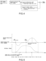
- a torque calculation portion as illustrated in FIG. 4 As a torque calculation portion in conventional throttle control, a torque calculation portion as illustrated in FIG. 4 is known.
- the configuration is as follows. An engine revolution speed deviation is calculated as a value obtained by subtracting, from a preset engine revolution speed command, an engine revolution speed calculated from a pulse period input from a crank pulse sensor, the product of the engine revolution speed deviation and a proportional torque coefficient is calculated as a proportional torque required for the engine, and the product of the engine revolution speed deviation and an integral torque coefficient is integrated to calculate an integral torque. The sum of the calculated proportional torque and integral torque is used as a torque command to request the engine.
- the present invention aims to enable control without excessive overshooting with respect to a revolution speed command at a time of revolution speed control, and enable quick convergence to the revolution speed command.
- the present invention made to solve the above problems provides an electronic throttle control method by which an electronic control unit controls opening/closing of a throttle while generating a control signal on the basis of an input data signal.
- the electronic control unit calculates an engine revolution speed deviation from a difference between an engine revolution speed and an engine revolution speed command, calculates an engine revolution acceleration on the basis of the engine revolution speed, calculates a proportional torque from the product of the engine revolution speed deviation and a proportional torque coefficient, calculates an integral torque by multiplying the integral of the product of the engine revolution speed deviation and an integral torque coefficient by a forgetting coefficient; and generates a control signal for the throttle, using the sum of the proportional torque and the integral torque as a torque command value.
- the present invention also provides an electronic throttle control device that includes: a throttle to which an actuator is attached; and an electronic control unit that controls opening and closing of the throttle via the actuator while generating a control signal on the basis of an input data signal.
- the electronic control unit includes: a revolution speed deviation calculation unit that calculates an engine revolution speed deviation from a difference between an engine revolution speed and an engine revolution speed command; a revolution acceleration calculation unit that calculates an engine revolution acceleration on the basis of the engine revolution speed; a proportional torque calculation unit that calculates a proportional torque from the product of the engine revolution speed deviation and a proportional torque coefficient; and an integral torque calculation unit that calculates an integral torque by multiplying the integral of the product of the engine revolution speed deviation and an integral torque coefficient by a forgetting coefficient.
- the forgetting coefficient is set to a value greater than 0 and smaller than 1, in a case where the engine revolution speed is higher than the engine revolution speed command, and the engine revolution acceleration is not lower than a set acceleration. In any other case, the forgetting coefficient is set to 1.
- an increase in the engine revolution speed at a time of removal of load is detected from the engine revolution speed and the engine revolution acceleration, and an integral torque is obtained by multiplication with the forgetting coefficient.
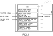
- FIG. 1 is a configuration diagram in which an electronic throttle control device according to an embodiment of the present invention is simplified.
- an electronic throttle control device 1 includes a throttle 20 to which an actuator (not illustrated) is attached, and an electronic control unit (ECU) 10 that is an electronic control means that controls opening/closing of the throttle 20.
- the electronic control unit 10 automatically controls opening/closing of the throttle 20 while generating a control signal by a predetermined calculation method on the basis of various data signals input thereto.
- the electronic control unit 10 includes means functionally formed with software stored in a storage means (not illustrated), which are: a revolution speed calculation unit 11 that calculates an engine revolution speed; a revolution speed deviation calculation unit 12 that calculates an engine revolution speed deviation; a revolution acceleration calculation unit 13 that calculates an engine revolution acceleration; a proportional torque calculation unit 14 that calculates a proportional torque; and an integral torque calculation unit 15 that calculates an integral torque.
- a revolution speed calculation unit 11 that calculates an engine revolution speed
- a revolution speed deviation calculation unit 12 that calculates an engine revolution speed deviation
- a revolution acceleration calculation unit 13 that calculates an engine revolution acceleration
- a proportional torque calculation unit 14 that calculates a proportional torque
- an integral torque calculation unit 15 that calculates an integral torque.
- the revolution speed calculation unit 11 calculates an engine revolution speed from a cycle of a pulse signal that is input from a crank pulse sensor (not illustrated), the revolution speed deviation calculation unit 12 calculates an engine revolution speed deviation from a difference between the engine revolution speed and an issued engine revolution speed command (a target revolution speed), and the revolution acceleration calculation unit 13 calculates an engine revolution acceleration on the basis of the engine revolution speed.
- the proportional torque calculation unit 14 and the integral torque calculation unit 15 calculate a proportional torque and an integral torque, to generate a control signal for the throttle 20, using the sum of the proportional torque and the integral torque as the value of a torque command.
- a forgetting coefficient is used in addition to an integral torque coefficient (an integral torque gain K i ), which is a feature of the present invention.
- the forgetting coefficient K FG is obtained under the following conditions A and B.
- the forgetting coefficient is set to a value greater than 0 and smaller than 1.
- an increase in the engine revolution speed at a time of removal of load is detected from the engine revolution speed and the engine revolution acceleration, and an integral torque is obtained by multiplication with the forgetting coefficient.
- an integral torque is obtained by multiplication with the forgetting coefficient.
Landscapes
- Engineering & Computer Science (AREA)
- Chemical & Material Sciences (AREA)
- Combustion & Propulsion (AREA)
- Mechanical Engineering (AREA)
- General Engineering & Computer Science (AREA)
- Electrical Control Of Air Or Fuel Supplied To Internal-Combustion Engine (AREA)
- Combined Controls Of Internal Combustion Engines (AREA)
- Control Of Throttle Valves Provided In The Intake System Or In The Exhaust System (AREA)
Abstract
In an electronic throttle control method by which an electronic control unit controls opening/closing of a throttle while generating a control signal on the basis of an input data signal, the electronic control unit calculates an engine revolution speed deviation from a difference between an engine revolution speed and an engine revolution speed command, calculates an engine revolution acceleration on the basis of the engine revolution speed, calculates a proportional torque from the product of the engine revolution speed deviation and a proportional torque coefficient, calculates an integral torque by multiplying the integral of the product of the engine revolution speed deviation and an integral torque coefficient by a forgetting coefficient; and generates a control signal for the throttle, using the sum of the proportional torque and the integral torque as a torque command value.
Description
- The present invention relates to a control method for opening and closing a throttle installed in the air intake system of an engine with an electronic control system, and an electronic throttle control device for implementing the control method.
- To perform engine control with high accuracy for the purpose of reducing fuel consumption and enhancing traveling performance of a vehicle in conventional cases, an electronic throttle control device that opens and closes a throttle through an operation of an electronic control unit that is an electronic control means, instead of mechanically opening and closing a throttle installed in the air intake system of the engine through an accelerator operation performed by the driver, is disclosed in
JP H05-240073 A - Further, as for such an electronic throttle control device,
JP 2008-038872 A JP 2022-148583 A - As a torque calculation portion in conventional throttle control, a torque calculation portion as illustrated in
FIG. 4 is known. The configuration is as follows. An engine revolution speed deviation is calculated as a value obtained by subtracting, from a preset engine revolution speed command, an engine revolution speed calculated from a pulse period input from a crank pulse sensor, the product of the engine revolution speed deviation and a proportional torque coefficient is calculated as a proportional torque required for the engine, and the product of the engine revolution speed deviation and an integral torque coefficient is integrated to calculate an integral torque. The sum of the calculated proportional torque and integral torque is used as a torque command to request the engine. - In such a conventional control method, when a load is applied, and the revolution speed deviation is positive (when the engine revolution speed is lower than the engine revolution speed command), the product of the engine revolution speed deviation and the integral torque coefficient (an integral torque gain Ki) is integrated, and the integral torque is integrated in accordance with the engine revolution speed deviation, to continue to become larger in the positive direction, as shown in the mathematical expression shown below.

- Torqi : integral torque
- Ki: integral torque gain
- ωref: engine revolution speed command
- w : engine revolution speed
- In a case where such a control system performs control so that the engine revolution speed is kept constant when load application and load removal are performed as illustrated in
FIG. 5 , the integral torque rises to a torque necessary to match the engine revolution speed with the engine revolution speed command, when a load is applied, and the engine revolution speed deviation is positive (when the engine revolution speed is lower than the engine revolution speed command). - After that, when load removal is performed, it takes a long time for the integral torque to return to a steady state at a time of no load. Therefore, there is a problem in that the engine revolution speed excessively overshoots with respect to the engine revolution speed command, or takes a long time to converge to the revolution speed command.
-
- Patent Literature 1:
JP H05-240073 A - Patent Literature 2:
JP 2008-038872 A - Patent Literature 3:
JP 2022-148583 A - The present invention aims to enable control without excessive overshooting with respect to a revolution speed command at a time of revolution speed control, and enable quick convergence to the revolution speed command.
- The present invention made to solve the above problems provides an electronic throttle control method by which an electronic control unit controls opening/closing of a throttle while generating a control signal on the basis of an input data signal. In this method, the electronic control unit calculates an engine revolution speed deviation from a difference between an engine revolution speed and an engine revolution speed command, calculates an engine revolution acceleration on the basis of the engine revolution speed, calculates a proportional torque from the product of the engine revolution speed deviation and a proportional torque coefficient, calculates an integral torque by multiplying the integral of the product of the engine revolution speed deviation and an integral torque coefficient by a forgetting coefficient; and generates a control signal for the throttle, using the sum of the proportional torque and the integral torque as a torque command value.
- The present invention also provides an electronic throttle control device that includes: a throttle to which an actuator is attached; and an electronic control unit that controls opening and closing of the throttle via the actuator while generating a control signal on the basis of an input data signal. In the electronic throttle control device, the electronic control unit includes: a revolution speed deviation calculation unit that calculates an engine revolution speed deviation from a difference between an engine revolution speed and an engine revolution speed command; a revolution acceleration calculation unit that calculates an engine revolution acceleration on the basis of the engine revolution speed; a proportional torque calculation unit that calculates a proportional torque from the product of the engine revolution speed deviation and a proportional torque coefficient; and an integral torque calculation unit that calculates an integral torque by multiplying the integral of the product of the engine revolution speed deviation and an integral torque coefficient by a forgetting coefficient.
- In the present invention, the forgetting coefficient is set to a value greater than 0 and smaller than 1, in a case where the engine revolution speed is higher than the engine revolution speed command, and the engine revolution acceleration is not lower than a set acceleration. In any other case, the forgetting coefficient is set to 1.
- According to the present invention, an increase in the engine revolution speed at a time of removal of load is detected from the engine revolution speed and the engine revolution acceleration, and an integral torque is obtained by multiplication with the forgetting coefficient. Thus, it is possible to perform control without excessive overshooting, and make the engine revolution speed to quickly converge to the revolution speed command.
-
-
FIG. 1 is a simplified configuration diagram of an electronic throttle control device according to an embodiment of the present invention; -
FIG. 2 is a functional block diagram illustrating details of control to be performed by the electronic throttle control device according to the embodiment illustrated inFIG. 1 ; -
FIG. 3 is a graph illustrating changes in integral torque in a case where load application and load removal are performed when an engine revolution speed is controlled to match an engine revolution speed command in an example of the control to be performed by the electronic throttle control device illustrated inFIG. 1 ; -
FIG. 4 is a functional block diagram illustrating details of control to be performed by a conventional electronic throttle control device; and -
FIG. 5 is a graph illustrating changes in integral torque in a case where load application and load removal are performed when an engine revolution speed is controlled to match an engine revolution speed command in an example of the control to be performed by the conventional electronic throttle control device. - The following is a description of an embodiment of the present invention, with reference to the drawings.
-
FIG. 1 is a configuration diagram in which an electronic throttle control device according to an embodiment of the present invention is simplified. As illustrated in this drawing, an electronicthrottle control device 1 includes a throttle 20 to which an actuator (not illustrated) is attached, and an electronic control unit (ECU) 10 that is an electronic control means that controls opening/closing of the throttle 20. Theelectronic control unit 10 automatically controls opening/closing of the throttle 20 while generating a control signal by a predetermined calculation method on the basis of various data signals input thereto. - Further, the
electronic control unit 10 includes means functionally formed with software stored in a storage means (not illustrated), which are: a revolutionspeed calculation unit 11 that calculates an engine revolution speed; a revolution speeddeviation calculation unit 12 that calculates an engine revolution speed deviation; a revolutionacceleration calculation unit 13 that calculates an engine revolution acceleration; a proportionaltorque calculation unit 14 that calculates a proportional torque; and an integraltorque calculation unit 15 that calculates an integral torque. - Referring next to a functional block diagram in
FIG. 2 and a graph inFIG. 3 , the control to be performed by theelectronic control unit 10 is described in detail. - First, in the present embodiment, the revolution
speed calculation unit 11 calculates an engine revolution speed from a cycle of a pulse signal that is input from a crank pulse sensor (not illustrated), the revolution speeddeviation calculation unit 12 calculates an engine revolution speed deviation from a difference between the engine revolution speed and an issued engine revolution speed command (a target revolution speed), and the revolutionacceleration calculation unit 13 calculates an engine revolution acceleration on the basis of the engine revolution speed. - The proportional
torque calculation unit 14 and the integraltorque calculation unit 15 calculate a proportional torque and an integral torque, to generate a control signal for the throttle 20, using the sum of the proportional torque and the integral torque as the value of a torque command. In the calculation of the integral torque shown below in a mathematical expression (1), a forgetting coefficient is used in addition to an integral torque coefficient (an integral torque gain Ki), which is a feature of the present invention. - [Math. 2]

- Torqi : integral torque
- Ki : integral torque gain
- ωref: engine revolution speed command
- ω : engine revolution speed
- KFG: forgetting coefficient
- The forgetting coefficient KFG is obtained under the following conditions A and B.
- Condition A: In a case where the engine revolution speed is higher than the engine revolution speed command, and the engine revolution acceleration is equal to or higher than a set acceleration, the forgetting coefficient KFG is set to a value greater than 0 and smaller than 1.
- Condition B: In any other case, the forgetting coefficient KFG is set to 1.
- As described above, in a case where the engine revolution speed is higher than the engine revolution speed command, and the engine revolution acceleration is equal to or higher than the set acceleration, which is when the engine is accelerating, the forgetting coefficient is set to a value greater than 0 and smaller than 1.
- With this arrangement, when the control for matching the engine revolution speed with the engine revolution speed command is performed, an increase in the engine revolution speed due to removal of load is detected, and the forgetting coefficient KFG is set to a value greater than 0 and smaller than 1. Thus, the time in which the integral torque returns from the value at the time of load application to a no-load state is shortened, the amount of overshooting of the engine revolution speed with respect to the engine revolution speed command is reduced, and the time of convergence of the engine revolution speed to the engine revolution speed command is also shortened.
- As described above, according to the present invention, an increase in the engine revolution speed at a time of removal of load is detected from the engine revolution speed and the engine revolution acceleration, and an integral torque is obtained by multiplication with the forgetting coefficient. Thus, it is possible to perform control without excessive overshooting, and make the engine revolution speed to quickly converge to the engine revolution speed command.
-
- 1
- Electronic throttle control device
- 10
- Electronic control unit (ECU)
- 11
- Revolution speed calculation unit
- 12
- Revolution speed deviation calculation unit
- 13
- Revolution acceleration calculation unit
- 14
- Proportional torque calculation unit
- 15
- Integral torque calculation unit
- 20
- Throttle
Claims (4)
- An electronic throttle control method by which an electronic control unit controls opening and closing of a throttle while generating a control signal on a basis of an input data signal, the electronic throttle control method comprising:by the electronic control unit,calculating an engine revolution speed deviation from a difference between an engine revolution speed and an engine revolution speed command;calculating an engine revolution acceleration on a basis of the engine revolution speed;calculating a proportional torque from a product of the engine revolution speed deviation and a proportional torque coefficient;calculating an integral torque by multiplying an integral of a product of the engine revolution speed deviation and an integral torque coefficient by a forgetting coefficient; andgenerating a control signal for the throttle, using a sum of the proportional torque and the integral torque as a torque command value.
- The electronic throttle control method according to claim 1, whereinthe forgetting coefficient isset to a value greater than 0 and smaller than 1, when the engine revolution speed is higher than the engine revolution speed command, and the engine revolution acceleration is not lower than a set acceleration, andthe forgetting coefficient is set to 1 in any other case.
- An electronic throttle control device (1) comprising: a throttle (2) to which an actuator is attached; and an electronic control unit (10) that controls opening and closing of the throttle (2) via the actuator while generating a control signal on a basis of an input data signal, wherein
the electronic control unit (10) includes:a revolution speed deviation calculation unit (12) configured to calculate an engine revolution speed deviation from a difference between an engine revolution speed and an engine revolution speed command;a revolution acceleration calculation unit (13) configured to calculate an engine revolution acceleration on a basis of the engine revolution speed;a proportional torque calculation unit (14) configured to calculate a proportional torque from a product of the engine revolution speed deviation and a proportional torque coefficient; andan integral torque calculation unit (15) configured to calculate an integral torque by multiplying an integral of a product of the engine revolution speed deviation and an integral torque coefficient by a forgetting coefficient. - The electronic throttle control device (1) according to claim 3, whereinthe forgetting coefficient isset to a value greater than 0 and smaller than 1, when the engine revolution speed is higher than the engine revolution speed command, and the engine revolution acceleration is not lower than a set acceleration, andthe forgetting coefficient is set to 1 in any other case.
Applications Claiming Priority (1)
| Application Number | Priority Date | Filing Date | Title |
|---|---|---|---|
| JP2023178887A JP2025068847A (en) | 2023-10-17 | 2023-10-17 | Electronic control method for throttle and electronically controlled throttle device |
Publications (1)
| Publication Number | Publication Date |
|---|---|
| EP4549720A1 true EP4549720A1 (en) | 2025-05-07 |
Family
ID=93010913
Family Applications (1)
| Application Number | Title | Priority Date | Filing Date |
|---|---|---|---|
| EP24204553.2A Pending EP4549720A1 (en) | 2023-10-17 | 2024-10-03 | Electronic throttle control method and electronic throttle control device |
Country Status (5)
| Country | Link |
|---|---|
| US (1) | US12523183B2 (en) |
| EP (1) | EP4549720A1 (en) |
| JP (1) | JP2025068847A (en) |
| KR (1) | KR20250055402A (en) |
| CN (1) | CN119844222A (en) |
Citations (5)
| Publication number | Priority date | Publication date | Assignee | Title |
|---|---|---|---|---|
| JPH05240073A (en) | 1992-02-28 | 1993-09-17 | Hitachi Ltd | Engine controller |
| JP2008038872A (en) | 2006-08-10 | 2008-02-21 | Nikki Co Ltd | Electronic control method of throttle and electronic control throttle device |
| WO2020160846A1 (en) * | 2019-02-08 | 2020-08-13 | Perkins Engines Company Limited | A method of controlling an internal combustion engine with a turbocharger |
| US20220307429A1 (en) * | 2021-03-24 | 2022-09-29 | Nikki Co., Ltd. | Electronic control method for throttle and electronic control throttle device |
| US20230043206A1 (en) * | 2021-08-02 | 2023-02-09 | Nikki Co., Ltd. | Electronic control method for throttle and electronic control throttle device |
Family Cites Families (5)
| Publication number | Priority date | Publication date | Assignee | Title |
|---|---|---|---|---|
| US5151861A (en) * | 1989-02-22 | 1992-09-29 | Mitsubishi Jidosha Kogyo Kabushiki Kaisha | Vehicle engine output control method and vehicle engine |
| JP2004340021A (en) * | 2003-05-15 | 2004-12-02 | Mitsubishi Electric Corp | Throttle valve control device |
| JP2005240073A (en) | 2004-02-24 | 2005-09-08 | Toshiba Corp | Plating film forming method, electromagnetic shielding material and casing |
| US8041487B2 (en) * | 2008-08-29 | 2011-10-18 | GM Global Technology Operations LLC | Commanded and estimated engine torque adjustment |
| JP7266856B2 (en) * | 2019-03-11 | 2023-05-01 | 株式会社ニッキ | Electronically controlled throttle controller |
-
2023
- 2023-10-17 JP JP2023178887A patent/JP2025068847A/en active Pending
-
2024
- 2024-09-10 KR KR1020240123344A patent/KR20250055402A/en active Pending
- 2024-10-03 EP EP24204553.2A patent/EP4549720A1/en active Pending
- 2024-10-12 CN CN202411423159.4A patent/CN119844222A/en active Pending
- 2024-10-16 US US18/918,031 patent/US12523183B2/en active Active
Patent Citations (6)
| Publication number | Priority date | Publication date | Assignee | Title |
|---|---|---|---|---|
| JPH05240073A (en) | 1992-02-28 | 1993-09-17 | Hitachi Ltd | Engine controller |
| JP2008038872A (en) | 2006-08-10 | 2008-02-21 | Nikki Co Ltd | Electronic control method of throttle and electronic control throttle device |
| WO2020160846A1 (en) * | 2019-02-08 | 2020-08-13 | Perkins Engines Company Limited | A method of controlling an internal combustion engine with a turbocharger |
| US20220307429A1 (en) * | 2021-03-24 | 2022-09-29 | Nikki Co., Ltd. | Electronic control method for throttle and electronic control throttle device |
| JP2022148583A (en) | 2021-03-24 | 2022-10-06 | 株式会社ニッキ | Electronic control method for throttle and electronically controlled throttle device |
| US20230043206A1 (en) * | 2021-08-02 | 2023-02-09 | Nikki Co., Ltd. | Electronic control method for throttle and electronic control throttle device |
Also Published As
| Publication number | Publication date |
|---|---|
| JP2025068847A (en) | 2025-04-30 |
| US20250146447A1 (en) | 2025-05-08 |
| KR20250055402A (en) | 2025-04-24 |
| CN119844222A (en) | 2025-04-18 |
| US12523183B2 (en) | 2026-01-13 |
Similar Documents
| Publication | Publication Date | Title |
|---|---|---|
| US4577718A (en) | Apparatus for controlling the speed of a vehicle with internal combustion engine | |
| EP0979934B1 (en) | Unit for controlling electronically controlled throttle valve | |
| US8720619B2 (en) | Method for operating a drive device of a hybird vehicle | |
| US20220307429A1 (en) | Electronic control method for throttle and electronic control throttle device | |
| EP0831223A2 (en) | Control apparatus for internal combustion engine using air-amount-first fuel-amount-second control method | |
| EP0924421B1 (en) | A fuel injection control device for an internal combustion engine | |
| KR900003858B1 (en) | Vehicle engine controller | |
| US5366039A (en) | Acceleration slip control device for a motor vehicle | |
| US7797992B2 (en) | Control apparatus for a source of rotational drive force | |
| US11761391B2 (en) | Electronic control method for throttle and electronic control throttle device | |
| US12523183B2 (en) | Electronic throttle control method and electronic throttle control device | |
| JPH0617684A (en) | Car acceleration control system | |
| US6328018B1 (en) | Control apparatus for controlling internal combustion engine | |
| EP4269773A1 (en) | Electronic control method for throttle and electronic control throttle device | |
| JP3613974B2 (en) | Vehicle speed control device | |
| JP2508657B2 (en) | Vehicle speed controller | |
| JP2566144B2 (en) | Throttle valve control device for internal combustion engine | |
| JPS60148723A (en) | Automatic control device for constant speed traveling | |
| JPH08216729A (en) | Constant speed travel control device for diesel engine vehicle | |
| JPH071019B2 (en) | Slot valve control device | |
| JPS6334305B2 (en) | ||
| JPH1199850A (en) | Vehicle speed control device | |
| JPH08295155A (en) | Vehicle constant-speed traveling device | |
| JPH06235343A (en) | Mixture control device for internal combustion engine | |
| JPS62231830A (en) | Constant speed travel control device for automobile |
Legal Events
| Date | Code | Title | Description |
|---|---|---|---|
| PUAI | Public reference made under article 153(3) epc to a published international application that has entered the european phase |
Free format text: ORIGINAL CODE: 0009012 |
|
| STAA | Information on the status of an ep patent application or granted ep patent |
Free format text: STATUS: THE APPLICATION HAS BEEN PUBLISHED |
|
| AK | Designated contracting states |
Kind code of ref document: A1 Designated state(s): AL AT BE BG CH CY CZ DE DK EE ES FI FR GB GR HR HU IE IS IT LI LT LU LV MC ME MK MT NL NO PL PT RO RS SE SI SK SM TR |
|
| STAA | Information on the status of an ep patent application or granted ep patent |
Free format text: STATUS: REQUEST FOR EXAMINATION WAS MADE |
|
| 17P | Request for examination filed |
Effective date: 20251104 |