EP4549715A1 - Gas turbine engine - Google Patents
Gas turbine engine Download PDFInfo
- Publication number
- EP4549715A1 EP4549715A1 EP24204408.9A EP24204408A EP4549715A1 EP 4549715 A1 EP4549715 A1 EP 4549715A1 EP 24204408 A EP24204408 A EP 24204408A EP 4549715 A1 EP4549715 A1 EP 4549715A1
- Authority
- EP
- European Patent Office
- Prior art keywords
- inductor
- tank
- hydrogen
- fuel
- fuel system
- Prior art date
- Legal status (The legal status is an assumption and is not a legal conclusion. Google has not performed a legal analysis and makes no representation as to the accuracy of the status listed.)
- Granted
Links
Images


Classifications
-
- F—MECHANICAL ENGINEERING; LIGHTING; HEATING; WEAPONS; BLASTING
- F02—COMBUSTION ENGINES; HOT-GAS OR COMBUSTION-PRODUCT ENGINE PLANTS
- F02C—GAS-TURBINE PLANTS; AIR INTAKES FOR JET-PROPULSION PLANTS; CONTROLLING FUEL SUPPLY IN AIR-BREATHING JET-PROPULSION PLANTS
- F02C7/00—Features, components parts, details or accessories, not provided for in, or of interest apart form groups F02C1/00 - F02C6/00; Air intakes for jet-propulsion plants
- F02C7/22—Fuel supply systems
- F02C7/224—Heating fuel before feeding to the burner
-
- B—PERFORMING OPERATIONS; TRANSPORTING
- B64—AIRCRAFT; AVIATION; COSMONAUTICS
- B64D—EQUIPMENT FOR FITTING IN OR TO AIRCRAFT; FLIGHT SUITS; PARACHUTES; ARRANGEMENT OR MOUNTING OF POWER PLANTS OR PROPULSION TRANSMISSIONS IN AIRCRAFT
- B64D37/00—Arrangements in connection with fuel supply for power plant
- B64D37/34—Conditioning fuel, e.g. heating
-
- B—PERFORMING OPERATIONS; TRANSPORTING
- B64—AIRCRAFT; AVIATION; COSMONAUTICS
- B64D—EQUIPMENT FOR FITTING IN OR TO AIRCRAFT; FLIGHT SUITS; PARACHUTES; ARRANGEMENT OR MOUNTING OF POWER PLANTS OR PROPULSION TRANSMISSIONS IN AIRCRAFT
- B64D37/00—Arrangements in connection with fuel supply for power plant
- B64D37/02—Tanks
- B64D37/06—Constructional adaptations thereof
- B64D37/10—Constructional adaptations thereof to facilitate fuel pressurisation
-
- B—PERFORMING OPERATIONS; TRANSPORTING
- B64—AIRCRAFT; AVIATION; COSMONAUTICS
- B64D—EQUIPMENT FOR FITTING IN OR TO AIRCRAFT; FLIGHT SUITS; PARACHUTES; ARRANGEMENT OR MOUNTING OF POWER PLANTS OR PROPULSION TRANSMISSIONS IN AIRCRAFT
- B64D37/00—Arrangements in connection with fuel supply for power plant
- B64D37/30—Fuel systems for specific fuels
-
- F—MECHANICAL ENGINEERING; LIGHTING; HEATING; WEAPONS; BLASTING
- F02—COMBUSTION ENGINES; HOT-GAS OR COMBUSTION-PRODUCT ENGINE PLANTS
- F02C—GAS-TURBINE PLANTS; AIR INTAKES FOR JET-PROPULSION PLANTS; CONTROLLING FUEL SUPPLY IN AIR-BREATHING JET-PROPULSION PLANTS
- F02C3/00—Gas-turbine plants characterised by the use of combustion products as the working fluid
- F02C3/20—Gas-turbine plants characterised by the use of combustion products as the working fluid using a special fuel, oxidant, or dilution fluid to generate the combustion products
- F02C3/22—Gas-turbine plants characterised by the use of combustion products as the working fluid using a special fuel, oxidant, or dilution fluid to generate the combustion products the fuel or oxidant being gaseous at standard temperature and pressure
-
- F—MECHANICAL ENGINEERING; LIGHTING; HEATING; WEAPONS; BLASTING
- F02—COMBUSTION ENGINES; HOT-GAS OR COMBUSTION-PRODUCT ENGINE PLANTS
- F02C—GAS-TURBINE PLANTS; AIR INTAKES FOR JET-PROPULSION PLANTS; CONTROLLING FUEL SUPPLY IN AIR-BREATHING JET-PROPULSION PLANTS
- F02C9/00—Controlling gas-turbine plants; Controlling fuel supply in air- breathing jet-propulsion plants
- F02C9/26—Control of fuel supply
- F02C9/40—Control of fuel supply specially adapted to the use of a special fuel or a plurality of fuels
-
- F—MECHANICAL ENGINEERING; LIGHTING; HEATING; WEAPONS; BLASTING
- F05—INDEXING SCHEMES RELATING TO ENGINES OR PUMPS IN VARIOUS SUBCLASSES OF CLASSES F01-F04
- F05D—INDEXING SCHEME FOR ASPECTS RELATING TO NON-POSITIVE-DISPLACEMENT MACHINES OR ENGINES, GAS-TURBINES OR JET-PROPULSION PLANTS
- F05D2300/00—Materials; Properties thereof
- F05D2300/50—Intrinsic material properties or characteristics
-
- Y—GENERAL TAGGING OF NEW TECHNOLOGICAL DEVELOPMENTS; GENERAL TAGGING OF CROSS-SECTIONAL TECHNOLOGIES SPANNING OVER SEVERAL SECTIONS OF THE IPC; TECHNICAL SUBJECTS COVERED BY FORMER USPC CROSS-REFERENCE ART COLLECTIONS [XRACs] AND DIGESTS
- Y02—TECHNOLOGIES OR APPLICATIONS FOR MITIGATION OR ADAPTATION AGAINST CLIMATE CHANGE
- Y02T—CLIMATE CHANGE MITIGATION TECHNOLOGIES RELATED TO TRANSPORTATION
- Y02T90/00—Enabling technologies or technologies with a potential or indirect contribution to GHG emissions mitigation
- Y02T90/40—Application of hydrogen technology to transportation, e.g. using fuel cells
Definitions
- This disclosure relates to fuel systems for hydrogen-fuelled aircraft propulsion systems, aircraft propulsion systems comprising such fuel systems, and methods of operations of such systems.
- the invention is directed towards a fuel system for a hydrogen fuelled aircraft propulsion system comprising:
- pressure within the liquid hydrogen tank can maintained during operation by heating of the fuel using electrical induction. As such, penetrations into the tank for the purposes of pressurisation are reduced.
- At least one of the first inductor and the second inductor may comprise a superconducting material.
- the superconducting material may comprise a type 2 superconductor such as cuprate, iron based, magnesium diboride, carbon-based or nickelate superconductor.
- the fuel system may comprise a controller configured to control heating of fuel in the tank.
- the controller may be configured to provide one of AC and variable DC current to the second inductor.
- the controller may be configured to operate the first inductor and second inductor in a charging mode and a heating mode.
- the controller In the charging mode, the controller may be configured to input current into the second inductor to energise the first inductor to a current density below its critical current density Jc.
- the controller In the heating mode, the controller may be configured to input current into the second inductor to energise the first inductor to a current density above its critical current density Jc.
- the controller can control the first inductor to discharge large quantities of heat into the hydrogen tank in a short period of time, by energising the first inductor to a current density above its critical density, wherein the first inductor no longer behaves as a superconductor, and "quenches", releasing its heat into the tank.
- the fuel system may comprise a plurality of first and second inductors.
- the controller may be configured to control a subset of the first and second inductors individually. As such, heat input can be controlled by selectively quenching a subset of second inductors.
- the hydrogen tank may be configured to store liquid hydrogen.
- the hydrogen tank may be configured to store liquid hydrogen at a pressure of between 1 and 4 Bar.
- the hydrogen tank may be configured to store liquid hydrogen at a temperature below 35 K.
- the hydrogen tank may be configured to store compressed or supercritical hydrogen.
- the tank may be configured to store hydrogen at a temperature below 100 K, and at a pressure up to 350 Bar.
- an aircraft propulsion system comprising a fuel system in accordance with the first aspect, and a propulsor.
- the propulsion system may comprise a fuel cell configured to provide electrical power the propulsor.
- the propulsion system may comprise a gas turbine engine configured to drive the propulsor.
- the aircraft engine may be configured to drive a generator configured to provide electrical power to the first inductor.
- a method of operating a fuel system of an aircraft propulsion system comprising: operating a second inductor located externally to a hydrogen tank to energise a first inductor provided within the tank to thereby heat hydrogen within the tank.
- the method may comprise, in a charging mode, inputting current into the second inductor to energise the second inductor comprising a superconducting material to a current density below its critical current density Jc.
- the method may comprise, in a heating mode, inputting current into the second inductor to energise the first inductor to a current density above its critical current density Jc to quench the first inductor.
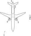
- FIG. 1 A hydrogen-fuelled airliner is illustrated in Figure 1 .
- the airliner 101 is of substantially conventional tube-and-wing twinjet configuration with a central fuselage 102 and substantially identical hydrogen powered propulsors 103.
- a hydrogen storage tank 104 is located in the fuselage 102.
- the hydrogen storage tank 104 is a cryogenic hydrogen storage tank and thus stores the hydrogen fuel in a liquid state, for example between 20 and 26 kelvin (K), and in a specific example at 25 K.
- the hydrogen fuel is pressurised to a pressure from around 1 bar to around 3 bar, in a specific example 2 bar.
- the hydrogen storage tank may be configured to store hydrogen in a gaseous or supercritical state, at above ambient pressure.
- the hydrogen may be cooled to a below ambient temperature for at least part of an operational cycle, and so the tank is configured to store hydrogen at cryogenic temperatures, to increase hydrogen storage density.
- the tank 104 is configured to store hydrogen at a pressure up to 350 Bar, and temperatures as low as 50 K, or as high as 400 K.
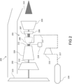
- FIG. 2 A block diagram of one of the hydrogen powered propulsors in the form of a gas turbine engine 103 is shown in Figure 2 , which shows a first fuel system 200 for the engine 103.
- the turbofan engine 103 comprises a core gas turbine 201.
- the core gas turbine 201 comprises, in fluid flow series, a low-pressure compressor 202, a high-pressure compressor 204, a fuel injection system 206, a combustor 207, a high-pressure turbine 208, a low-pressure turbine 209, and a core nozzle 210.
- the high-pressure compressor 204 is driven by the high-pressure turbine 208 via a first shaft 211
- the low-pressure compressor 203 is driven by the low-pressure turbine 209 via a second shaft 212.
- the core gas turbine could be of three-shaft configuration.
- the low-pressure turbine 209 drives a fan 213 via shaft 212.
- hydrogen fuel is pumped from the hydrogen storage tank 104 by a pump 216 and into a main fuel conduit 217 which ultimately delivers fuel to the fuel injection system 206.
- the pump 216 may be driven by an electric machine (not shown) or via one or more of the gas turbine engine core shafts 211, 212 via an auxiliary gearbox, or by a turbine powered by heated fuel, exhaust gases from the preheater, or compressed air from the core compressor.
- the pump provides a "head" of pressure, raising the pressure from the inlet (defined by the pressure conditions upstream of the pump, in particular tank pressure), to a higher pressure at an outlet.
- the propulsion system comprises a gas turbine engine driven electrical generator 218, which is typically driven by one of the engine shafts (the high-pressure shaft 211 in the embodiment of figure 2 ), and is configured to provide electrical power to one or more systems.
- Figure 3 shows an alternative propulsion system 300 for the aircraft 101.
- the propulsion system comprises a fan 313 driven by an electric motor 320.
- the electric motor 320 is in turn energised by electrical power provided from a hydrogen fuel cell 322.
- the hydrogen fuel cell 322 is provided with fuel by a fuel system 200 which is essentially the same as the system shown in figure 2 , and is configured to generate electrical power, which can also be provided to various aircraft systems in addition to the electric motor 320.
- Figure 4 shows part of the fuel system 200 in further detail, comprising a fuel heating system 430.
- any penetrations of the tank 104 represent a heat flow path into the tank 104, which can result in uncontrolled heating of the tank contents and reduces storage life. Additionally, any penetration may be difficult to seal, and may result in leaks. Leaks are particularly difficult to avoid in hydrogen storage systems in view of the low molecular size of dihydrogen. Additionally, hydrogen leaks may represent a fire risk.
- the present invention provides a system which pressurises the tank, with a minimum of tank penetrations.
- the system comprises an induction heating system comprising first 436a-c and second 432a-c inductors.
- three second inductors 432a, 432b, 432c are provided.
- Each second inductor 432a-c comprises a coil of conductive material such as copper, and typically comprises a magnetic core to increase the magnetic field produced by the inductor.
- Each second inductor 432a-c is electrically coupled to either an Alternating Current (AC) or variable Direct Current (DC) source comprising a controller 434, which is itself coupled to a current source such as the engine electrical generator 218, fuel cell 320, or other suitable power source such as a battery. Where the generator 218 is an AC generator, a rectifier may be provided to convert AC current to DC current.
- Each second inductor 432a-c is provided adjacent the fuel tank 104, in close proximity to the tank wall, but outside of the tank volume. As such, no penetrations into the tank are required to install the coils 432a-c.
- Each second inductor 432a-c is magnetically linked to a respective first inductor 436a-c.
- Each first inductor 436a-c is installed inside the tank volume, and is arranged to be in thermal contact with hydrogen fuel when the tank 104 is fuelled.
- the first inductors 436a-c are of a similar construction to the second inductors 436a-c, comprising conventional conductive material coils such as copper wound around a magnetic core.
- the controller 434 provides electrical power to the second inductors 432a-c as required in accordance with a tank heating schedule.
- either AC or DC electrical power having a time varying (e.g. sinusoidal) magnitude provided to the second inductors 432a-c induces a magnetic field, which interacts with the first inductors 436a-c to generate an electrical current in the first inductors 436a-c.
- This current causes resistive heating in the first inductors 436a-c, which generates heat within the tank 104.
- the tank 104 contains liquid hydrogen, a portion of the hydrogen will vaporise, increasing the pressure in the tank. Similarly, where the tank contains compressed gaseous hydrogen, heating of the hydrogen will again raise the pressure.
- the inductors 436a-c, 432a-c act as a transformer, providing inductive heating to the tank contents.
- the number of turns of the second inductors 432a-c may be higher than the number of turns in the first inductors 436a-c to increase the current in the first inductors 436a-c relative to the second inductors 432a-c, to increase the current in the first inductors 436a-c, thereby increasing resistive heating in the first inductors 436a-c relative to the second inductors 432a-c.
- each of the first inductors 436a-c comprises a coil formed of a superconducting material which is capable of superconduction at temperatures and conditions encountered within the hydrogen tank 104 during operation. In the case of a hydrogen tank configured to store liquid hydrogen, temperatures during operation are typically below 25 K.
- Suitable superconductor materials include so-called "high temperature” superconductors.
- Superconductors that do not exhibit the so-called “Meissner effect” i.e. type 2 superconductors
- An additional desirable characteristic is the presence of superconductivity at low pressures, since the pressures encountered in the hydrogen tank will vary, and may be close to 1 atmosphere, and the first inductors 436a-c must be in thermal contact with the hydrogen within the tank 104.
- a high critical current density (J c ) is also desirable.
- the critical current density is the current density (given in amps per area, e.g. A/mm 2 ) above which superconductivity is lost.
- any of the above materials listed in Table 1 provide suitable candidates, with MgB 2 being particularly suitable in view of its high Jc, low cost, and suitability for drawing into a wire. Additionally, the Tc is relatively close to that of liquid hydrogen storage temperatures, making it easier to quench. YBCO may also be suitable, but may be susceptible to damage during repeated heating and cooling cycles. BSSCO may also be suitable.
- the second inductors 432a-c may also comprise superconducting material.
- heat generation from the coils outside the tank is minimised, since only heat generation within the tank is desired. Consequently, the efficiency of the system is increased.
- the second inductors 432a-c may be in thermal contact with hydrogen fuel in the fuel conduit 217, downstream of the tank 104. Consequently, the inductors 432a-c can be kept below their critical temperature in use.
- a method of operation is defined.
- the controller 434 operates one or more first inductors 432a-c to generate a current in the second inductors 436a-c.
- the current in the first inductors 436a-c is maintained below the critical current Jc, such that the first inductors act as superconductors, and substantially no heat is added to the fuel.
- This mode is referred to as a "charging" mode, since the second inductors 436a-c are energised by the second inductors 432a-c, with no release of energy into the tank 104.
- the controller 434 ceases providing current to the first inductor 432a, and charging ends. Once charged, the first inductors can store current for long periods of time, provided the tank conditions allow for superconductivity.
- a heating mode begins.
- additional time varying DC current is applied to the second inductors 432a-c, to increase the current density in the first inductors 436a-c to a value above the critical current density Jc. Accordingly, the first inductors 436a-c are quenched, and heat is released into the tank 104.
- a subset only of the second inductors 436a-c are quenched during the heating step, to control the quantity of heat added to the tank.
- the first inductors 436a-c can be discharged by the provision of time varying DC current to the second inductors 432a-c having a reversed polarity relative to the DC current used in the charging phase. As such, the first inductors 436a-c can be safely discharged without suddenly releasing energy to the hydrogen tank.
- a discharging mode may allow for discharging of the inductors 436a-c prior to warming the tank in between flight cycles, or in the event of an emergency, in which the tank 104 is likely to rapidly warm.
- first inductors comprise conventional conductors.
- first inductors comprise conventional conductors.
- large quantities of heat can be added over a short time period, without a requirement for a high power from the controller 434, generator 218 / fuel cell 320, or second inductors 432a-c.
- each of these systems can be sized for continuous heating requirements, rather than peak heating requirements.
- the fuel flow and pressure requirements vary significantly during use.
- the tank 104 may contain a relatively small ullage space.
- a relatively small withdrawal of liquid hydrogen volume may result in a large decrease in tank pressure.
- the volume of the remaining hydrogen is relatively high, and the temperature of the hydrogen is low, and so large quantities of heat may be required to vaporise sufficient hydrogen to replace the liquid hydrogen drained from the tank in view of the heat capacity of the remaining fuel.
- fuel flows are often greatest during take-off, where power requirements are high.
- take-off represents a "corner point", which must be designed for, but which represents a much more challenging design point than the remaining operation.
- a heating system designed for heating input sufficient for take-off may be very large and heavy.
- the first inductors 436a-c can be charged during start-up and taxi, where fuel flow demands are low, with the first inductors 436a-c being quenched, and providing heat into the tank 104 during take-off.
- the invention provides a tank pressurisation system which has weight and power advantages over prior systems, in addition to a reduction in tank penetrations, and so reduced thermal bridging and leakage risk.
- the aircraft propulsion system could comprise a hybrid propulsion system, with both a gas turbine engine and a hydrogen fuel cell.
- the gas turbine engine would provide at least one or direct mechanical power and electrical power to drive a propulsor.
- the fuel cell would provide electrical power to drive either the same, or a separate propulsor to the one driven by the gas turbine engine.
- Such a system may further comprise electrical energy storage such as a battery.
Landscapes
- Engineering & Computer Science (AREA)
- Chemical & Material Sciences (AREA)
- Combustion & Propulsion (AREA)
- Aviation & Aerospace Engineering (AREA)
- Mechanical Engineering (AREA)
- General Engineering & Computer Science (AREA)
- Filling Or Discharging Of Gas Storage Vessels (AREA)
Abstract
Description
- This disclosure relates to fuel systems for hydrogen-fuelled aircraft propulsion systems, aircraft propulsion systems comprising such fuel systems, and methods of operations of such systems.
- In order to limit emissions of carbon dioxide, use of hydrogen as an alternative to hydrocarbon fuel in gas turbine engines has historically only been practical in land-based installations. However, more recently there has been interest in aircraft powered by hydrogen stored at cryogenic temperatures, typically as either a liquid, a compressed gas, or a supercritical fluid.
- As the tank is drained during use, the pressure within the tank will fall. In a conventional fuel system, this fuel would be replaced with inert gas such as nitrogen to prevent the pressure from falling below a minimum pressure required for effective pumping and tank structural requirements. However, in a hydrogen tank in which the fuel is stored at low temperatures, such conventional tank pressurisation systems are ineffective as the nitrogen would be liquified at the low temperatures present in the tank where the hydrogen is stored as a liquid, and would mix with the hydrogen fuel where it is stored as a gas. The present invention seeks to provide a fuel system which overcomes these problems.
- The invention is directed towards a fuel system for a hydrogen fuelled aircraft propulsion system comprising:
- a tank configured to store hydrogen;
- a first inductor provided within the tank and configured to heat hydrogen fuel within the tank; and
- a second inductor provided externally to the tank, and configured to induce a current in the first inductor.
- Advantageously, pressure within the liquid hydrogen tank can maintained during operation by heating of the fuel using electrical induction. As such, penetrations into the tank for the purposes of pressurisation are reduced.
- At least one of the first inductor and the second inductor may comprise a superconducting material. The superconducting material may comprise a type 2 superconductor such as cuprate, iron based, magnesium diboride, carbon-based or nickelate superconductor.
- The fuel system may comprise a controller configured to control heating of fuel in the tank. The controller may be configured to provide one of AC and variable DC current to the second inductor. The controller may be configured to operate the first inductor and second inductor in a charging mode and a heating mode. In the charging mode, the controller may be configured to input current into the second inductor to energise the first inductor to a current density below its critical current density Jc. In the heating mode, the controller may be configured to input current into the second inductor to energise the first inductor to a current density above its critical current density Jc. Accordingly, the controller can control the first inductor to discharge large quantities of heat into the hydrogen tank in a short period of time, by energising the first inductor to a current density above its critical density, wherein the first inductor no longer behaves as a superconductor, and "quenches", releasing its heat into the tank.
- The fuel system may comprise a plurality of first and second inductors. The controller may be configured to control a subset of the first and second inductors individually. As such, heat input can be controlled by selectively quenching a subset of second inductors.
- The hydrogen tank may be configured to store liquid hydrogen. The hydrogen tank may be configured to store liquid hydrogen at a pressure of between 1 and 4 Bar. The hydrogen tank may be configured to store liquid hydrogen at a temperature below 35 K.
- Alternatively, the hydrogen tank may be configured to store compressed or supercritical hydrogen. The tank may be configured to store hydrogen at a temperature below 100 K, and at a pressure up to 350 Bar.
- In a second aspect there is provided an aircraft propulsion system comprising a fuel system in accordance with the first aspect, and a propulsor.
- The propulsion system may comprise a fuel cell configured to provide electrical power the propulsor.
- Alternatively or in addition, the propulsion system may comprise a gas turbine engine configured to drive the propulsor.
- The aircraft engine may be configured to drive a generator configured to provide electrical power to the first inductor.
- In a third aspect, there is provided a method of operating a fuel system of an aircraft propulsion system comprising:
operating a second inductor located externally to a hydrogen tank to energise a first inductor provided within the tank to thereby heat hydrogen within the tank. - The method may comprise, in a charging mode, inputting current into the second inductor to energise the second inductor comprising a superconducting material to a current density below its critical current density Jc.
- The method may comprise, in a heating mode, inputting current into the second inductor to energise the first inductor to a current density above its critical current density Jc to quench the first inductor.
- An embodiment will now be described by way of example only with reference to the accompanying drawings, which are purely schematic and not to scale, and in which:
-
Figure 1 shows a hydrogen-fuelled aircraft comprising a hydrogen-fuelled propulsion system; -
Figure 2 is a block diagram of a propulsion system for the aircraft of 1igure 1 including a fuel system; -
Figure 3 is a block diagram of an alternative propulsion system for the aircraft offigure 1 ; -
Figure 4 is a block diagram of part of the fuel system for the propulsion systems offigure 2 orfigure 3 , comprising a fuel tank and tank heating system; and -
Figure 5 is a flow diagram illustrating a method of use of the fuel system offigures 2 to 4 . - A hydrogen-fuelled airliner is illustrated in
Figure 1 . In this example, theairliner 101 is of substantially conventional tube-and-wing twinjet configuration with acentral fuselage 102 and substantially identical hydrogen poweredpropulsors 103. - A
hydrogen storage tank 104 is located in thefuselage 102. In the present embodiment, thehydrogen storage tank 104 is a cryogenic hydrogen storage tank and thus stores the hydrogen fuel in a liquid state, for example between 20 and 26 kelvin (K), and in a specific example at 25 K. In this example, the hydrogen fuel is pressurised to a pressure from around 1 bar to around 3 bar, in a specific example 2 bar. - In alternative embodiments, the hydrogen storage tank may be configured to store hydrogen in a gaseous or supercritical state, at above ambient pressure. The hydrogen may be cooled to a below ambient temperature for at least part of an operational cycle, and so the tank is configured to store hydrogen at cryogenic temperatures, to increase hydrogen storage density. In one example, the
tank 104 is configured to store hydrogen at a pressure up to 350 Bar, and temperatures as low as 50 K, or as high as 400 K. - A block diagram of one of the hydrogen powered propulsors in the form of a
gas turbine engine 103 is shown inFigure 2 , which shows a first fuel system 200 for theengine 103. - The
turbofan engine 103 comprises acore gas turbine 201. - The
core gas turbine 201 comprises, in fluid flow series, a low-pressure compressor 202, a high-pressure compressor 204, afuel injection system 206, acombustor 207, a high-pressure turbine 208, a low-pressure turbine 209, and acore nozzle 210. The high-pressure compressor 204 is driven by the high-pressure turbine 208 via afirst shaft 211, and the low-pressure compressor 203 is driven by the low-pressure turbine 209 via asecond shaft 212. It will be appreciated that in alternative embodiments, the core gas turbine could be of three-shaft configuration. - In operation, the low-
pressure turbine 209 drives afan 213 viashaft 212. - In operation, hydrogen fuel is pumped from the
hydrogen storage tank 104 by apump 216 and into amain fuel conduit 217 which ultimately delivers fuel to thefuel injection system 206. Thepump 216 may be driven by an electric machine (not shown) or via one or more of the gas turbineengine core shafts - The propulsion system comprises a gas turbine engine driven
electrical generator 218, which is typically driven by one of the engine shafts (the high-pressure shaft 211 in the embodiment offigure 2 ), and is configured to provide electrical power to one or more systems. -
Figure 3 shows analternative propulsion system 300 for theaircraft 101. In this example, the propulsion system comprises afan 313 driven by anelectric motor 320. Theelectric motor 320 is in turn energised by electrical power provided from ahydrogen fuel cell 322. Thehydrogen fuel cell 322 is provided with fuel by a fuel system 200 which is essentially the same as the system shown infigure 2 , and is configured to generate electrical power, which can also be provided to various aircraft systems in addition to theelectric motor 320. -
Figure 4 shows part of the fuel system 200 in further detail, comprising afuel heating system 430. - In operation, fuel is consumed by either the
engine 201 orfuel cell 320. In either case, withdrawal of fuel from thetank 104 results in a lower volume of fuel within thetank 104. If this volume is not replaced, the tank pressure will drop. Reduced tank pressure increases the work required by thepump 216 to deliver fuel to theengine 201 orfuel cell 320, and so reduces propulsion system efficiency. This may also increase required pump size (and therefore weight) to provide the required head, and risks cavitation if the pressure drops too far. In extreme cases, a drop in pressure to below ambient pressure may result in damage to the tank. Additionally, rapid pressure fluctuations result in mechanical cycling of thetank 104, which may result in material fatigue and reduced tank life. Accordingly, it is desirable to maintain relatively constant pressure during operation, or at least prevent pressure from dropping below a predetermined level. - The inventors have found that various challenges are encountered when designing a tank pressurisation system. It is desirable to reduce tank penetrations to a minimum, since any penetrations of the
tank 104 represent a heat flow path into thetank 104, which can result in uncontrolled heating of the tank contents and reduces storage life. Additionally, any penetration may be difficult to seal, and may result in leaks. Leaks are particularly difficult to avoid in hydrogen storage systems in view of the low molecular size of dihydrogen. Additionally, hydrogen leaks may represent a fire risk. - Accordingly, the present invention provides a system which pressurises the tank, with a minimum of tank penetrations.
- The system comprises an induction heating system comprising first 436a-c and second 432a-c inductors. In the present embodiment three
second inductors second inductor 432a-c comprises a coil of conductive material such as copper, and typically comprises a magnetic core to increase the magnetic field produced by the inductor. Eachsecond inductor 432a-c is electrically coupled to either an Alternating Current (AC) or variable Direct Current (DC) source comprising acontroller 434, which is itself coupled to a current source such as the engineelectrical generator 218,fuel cell 320, or other suitable power source such as a battery. Where thegenerator 218 is an AC generator, a rectifier may be provided to convert AC current to DC current. Eachsecond inductor 432a-c is provided adjacent thefuel tank 104, in close proximity to the tank wall, but outside of the tank volume. As such, no penetrations into the tank are required to install thecoils 432a-c. - Each
second inductor 432a-c is magnetically linked to a respectivefirst inductor 436a-c. Eachfirst inductor 436a-c is installed inside the tank volume, and is arranged to be in thermal contact with hydrogen fuel when thetank 104 is fuelled. - In one embodiment, the
first inductors 436a-c are of a similar construction to thesecond inductors 436a-c, comprising conventional conductive material coils such as copper wound around a magnetic core. - In operation, the
controller 434 provides electrical power to thesecond inductors 432a-c as required in accordance with a tank heating schedule. As will be understood, either AC or DC electrical power having a time varying (e.g. sinusoidal) magnitude provided to thesecond inductors 432a-c induces a magnetic field, which interacts with thefirst inductors 436a-c to generate an electrical current in thefirst inductors 436a-c. This current causes resistive heating in thefirst inductors 436a-c, which generates heat within thetank 104. Where thetank 104 contains liquid hydrogen, a portion of the hydrogen will vaporise, increasing the pressure in the tank. Similarly, where the tank contains compressed gaseous hydrogen, heating of the hydrogen will again raise the pressure. As such, theinductors 436a-c, 432a-c act as a transformer, providing inductive heating to the tank contents. In some embodiments, the number of turns of thesecond inductors 432a-c may be higher than the number of turns in thefirst inductors 436a-c to increase the current in thefirst inductors 436a-c relative to thesecond inductors 432a-c, to increase the current in thefirst inductors 436a-c, thereby increasing resistive heating in thefirst inductors 436a-c relative to thesecond inductors 432a-c. - In a further embodiment, which can also be illustrated with reference to
figure 4 , the construction of thefirst inductors 436a-c may differ significantly to that of thesecond inductors 432a-c. In this embodiment, each of thefirst inductors 436a-c comprises a coil formed of a superconducting material which is capable of superconduction at temperatures and conditions encountered within thehydrogen tank 104 during operation. In the case of a hydrogen tank configured to store liquid hydrogen, temperatures during operation are typically below 25 K. - Suitable superconductor materials include so-called "high temperature" superconductors. Superconductors that do not exhibit the so-called "Meissner effect" (i.e. type 2 superconductors) are most suitable, since these do not repel external magnetic fields, and are more suitable for use as part of a transformer. An additional desirable characteristic is the presence of superconductivity at low pressures, since the pressures encountered in the hydrogen tank will vary, and may be close to 1 atmosphere, and the
first inductors 436a-c must be in thermal contact with the hydrogen within thetank 104. A high critical current density (Jc) is also desirable. The critical current density is the current density (given in amps per area, e.g. A/mm2) above which superconductivity is lost. Additionally, engineering considerations such as the ability to produce a wire of the material are important.Table 1 below gives examples of suitable superconductor materials: Material name Chemical Formula TC (K) JC Oxo-cuprate Hg12Tl3Ba30Ca30Cu45O127 138 BSCCO Bi2Sr2Ca2Cu3O10 110 5 YBCO YBa2Cu3O7 92 8 kA/cm2 at 1 Tesla (T) and 36 K[1] SmFeAsO0.85F0.15 56 105 A/cm2 at 45 T and 4.2 K[2] CeOFeAs 41 Magnesium Diboride MgB2 39 300 kA/cm2 at 0.5 T, 10 K La2-xBaxCuO4 30 [1] - A. Koblischka-Veneva et al., "Comparison of Temperature and Field Dependencies of the Critical Current Densities of Bulk YBCO, MgB2, and Iron-Based Superconductors," in IEEE Transactions on Applied Superconductivity, vol. 29, no. 5, pp. 1-5, Aug. 2019, Art no. 6801805, doi: 10.1109/TASC.2019.2900932.
[2] - lida, K., Hänisch, J., Tarantini, C. et al. Oxypnictide SmFeAs(O,F) superconductor: a candidate for high-field magnet applications. Sci Rep 3, 2139 (2013). https://doi.org/10.1038/srep02139. - As can be seen, any of the above materials listed in Table 1 provide suitable candidates, with MgB2 being particularly suitable in view of its high Jc, low cost, and suitability for drawing into a wire. Additionally, the Tc is relatively close to that of liquid hydrogen storage temperatures, making it easier to quench. YBCO may also be suitable, but may be susceptible to damage during repeated heating and cooling cycles. BSSCO may also be suitable.
- As will be understood, while operating as a superconductor (i.e. below its critical temperature, current density and magnetic field), superconducting materials conduct electrical current without any resistive losses. As such, current circulating within the
first inductors 436a-c will not generate heat. However, the current can continue to increase by operation of thesecond inductors 432a-c where energised with time varying DC current (i.e. where the polarity does not reverse), until the critical current density is reached. Once the critical current density is exceeded, thefirst inductors 436a-c will "quench", i.e. cease to operate as superconductors. Accordingly, the resistivity of therespective inductors 436a-c will increase dramatically, leading to Joule heating, and heat transfer to the hydrogen fuel within thetank 104. - In a modification to this system, the
second inductors 432a-c may also comprise superconducting material. In this case, heat generation from the coils outside the tank is minimised, since only heat generation within the tank is desired. Consequently, the efficiency of the system is increased. As shown infigure 4 , thesecond inductors 432a-c may be in thermal contact with hydrogen fuel in thefuel conduit 217, downstream of thetank 104. Consequently, theinductors 432a-c can be kept below their critical temperature in use. - Accordingly, referring to
figure 5 , a method of operation is defined. In a first mode, thecontroller 434 operates one or morefirst inductors 432a-c to generate a current in thesecond inductors 436a-c. During operation in the first mode, the current in thefirst inductors 436a-c is maintained below the critical current Jc, such that the first inductors act as superconductors, and substantially no heat is added to the fuel. This mode is referred to as a "charging" mode, since thesecond inductors 436a-c are energised by thesecond inductors 432a-c, with no release of energy into thetank 104. Once the critical current density Jc is almost reached, but not exceeded, thecontroller 434 ceases providing current to thefirst inductor 432a, and charging ends. Once charged, the first inductors can store current for long periods of time, provided the tank conditions allow for superconductivity. - When addition of heat is required to raise the pressure within the
tank 104, a heating mode begins. In the heating mode, additional time varying DC current is applied to thesecond inductors 432a-c, to increase the current density in thefirst inductors 436a-c to a value above the critical current density Jc. Accordingly, thefirst inductors 436a-c are quenched, and heat is released into thetank 104. - In some cases, a subset only of the
second inductors 436a-c are quenched during the heating step, to control the quantity of heat added to the tank. - In a third mode, the
first inductors 436a-c can be discharged by the provision of time varying DC current to thesecond inductors 432a-c having a reversed polarity relative to the DC current used in the charging phase. As such, thefirst inductors 436a-c can be safely discharged without suddenly releasing energy to the hydrogen tank. Such a discharging mode may allow for discharging of theinductors 436a-c prior to warming the tank in between flight cycles, or in the event of an emergency, in which thetank 104 is likely to rapidly warm. - This arrangement provides additional advantages compared to the system in which the first inductors comprise conventional conductors. In this system, large quantities of heat can be added over a short time period, without a requirement for a high power from the
controller 434,generator 218 /fuel cell 320, orsecond inductors 432a-c. As such, each of these systems can be sized for continuous heating requirements, rather than peak heating requirements. - For example, where the propulsion system comprises a
gas turbine engine 203, the fuel flow and pressure requirements vary significantly during use. For example, at the beginning of a flight, thetank 104 may contain a relatively small ullage space. As such, a relatively small withdrawal of liquid hydrogen volume may result in a large decrease in tank pressure. At the same time, the volume of the remaining hydrogen is relatively high, and the temperature of the hydrogen is low, and so large quantities of heat may be required to vaporise sufficient hydrogen to replace the liquid hydrogen drained from the tank in view of the heat capacity of the remaining fuel. Furthermore, fuel flows are often greatest during take-off, where power requirements are high. - As such, take-off represents a "corner point", which must be designed for, but which represents a much more challenging design point than the remaining operation. A heating system designed for heating input sufficient for take-off may be very large and heavy. In the present embodiment, the
first inductors 436a-c can be charged during start-up and taxi, where fuel flow demands are low, with thefirst inductors 436a-c being quenched, and providing heat into thetank 104 during take-off. - Accordingly, the invention provides a tank pressurisation system which has weight and power advantages over prior systems, in addition to a reduction in tank penetrations, and so reduced thermal bridging and leakage risk.
- Various examples have been described, each of which comprise various combinations of features. It will be appreciated by those skilled in the art that, except where clearly mutually exclusive, any of the features may be employed separately or in combination with any other features and thus the disclosed subject-matter extends to and includes all such combinations and sub-combinations of the or more features described herein.
- Modifications could be made to the disclosed arrangement.
- For example, the aircraft propulsion system could comprise a hybrid propulsion system, with both a gas turbine engine and a hydrogen fuel cell. In such a system, the gas turbine engine would provide at least one or direct mechanical power and electrical power to drive a propulsor. The fuel cell would provide electrical power to drive either the same, or a separate propulsor to the one driven by the gas turbine engine. Such a system may further comprise electrical energy storage such as a battery.
Claims (15)
- A fuel system (200) for a hydrogen fuelled aircraft propulsion system (103) comprising:a tank (104) configured to store hydrogen;a first inductor (436a-c) provided within the tank (104) and configured to heat hydrogen fuel within the tank (104); anda second inductor (432a-c) provided externally to the tank (104), and configured to induce a current in the first inductor (436a-c).
- A fuel system according to claim 1, wherein at least one of the first inductor (436a-c) and the second inductor (432a-c) comprises a superconducting material and may comprise a type 2 superconductor such as cuprate, iron based, magnesium diboride, carbon-based or nickelate superconductor.
- A fuel system according to any of the preceding claims, wherein the fuel system comprises a controller (434) configured to control heating of fuel in the tank (104) and configured to provide one of AC and variable DC current to the second inductor (432a-c).
- A fuel system according to claim 3 when dependent on claim 2, wherein the controller (434) is configured to operate the first inductor (436a-c) and second inductor (432a-c) in a charging mode and a heating mode
- A fuel system according to claim 4, wherein, in the charging mode, the controller (434) is configured to input current into the second inductor (432a-c) to energise the first inductor (436a-c) to a current density below its critical current density Jc.
- A fuel system according to claim 4 or claim 5, wherein, In the heating mode, the controller (434) is configured to input current into the second inductor (432a-c) to energise the first inductor (436a-c) to a current density above its critical current density Jc.
- A fuel system according to any of the preceding claims, wherein the fuel system comprises a plurality of first and second inductors (436a-c, 432a-c).
- A fuel system according to claim 7 when dependent on claim 3 or any claim dependent thereon, wherein the controller (434) is configured to control a subset of the first and second inductors (436a-c, 432a-c) individually.
- A fuel system according to any of the preceding claims, wherein the hydrogen tank (104) is configured to store liquid hydrogen, and wherein the hydrogen tank (104) may configured to store liquid hydrogen at a pressure of between 1 and 4 Bar, and may be configured to store liquid hydrogen at a temperature below 35 K.
- A fuel system according to any of claims 1 to 9, wherein the hydrogen tank (104) is configured to store compressed or supercritical hydrogen, and wherein the hydrogen tank (104) may be configured to store hydrogen at a temperature below 100 K, and at a pressure up to 350 Bar.
- An aircraft propulsion system (103) comprising a fuel system (200) in accordance with any of the preceding claims, and a propulsor (213).
- An aircraft propulsion system according to claim 11, wherein the propulsion system comprises one or more of a fuel cell (322) configured to provide electrical power the propulsor (213), and a gas turbine engine (201) configured to drive the propulsor (213).
- A method of operating a fuel system (200) of an aircraft propulsion system (103) comprising:
operating a second inductor (432a-c) located externally to a hydrogen tank (104) to energise a first inductor (436a-c) provided within the tank (104) to thereby heat hydrogen within the tank (104). - A method according to claim 13, wherein the method comprises, in a charging mode, inputting current into the first inductor (436a-c) comprising a superconducting material to energise the second coil to a current density below its critical current density JC.
- A method according to claim 13 or claim 14, wherein the method comprises, in a heating mode, inputting current into the second inductor (432a-c) to energise the first inductor (436a-c) comprising a superconducting material to a current density above its critical current density JC to quench the first inductor (436a-c); and, in a heating mode, inputting current into the second inductor (324a-c) to energise the first inductor (432a-c) to a current density above its critical current density Jc to quench the first inductor (436a-c).
Applications Claiming Priority (1)
| Application Number | Priority Date | Filing Date | Title |
|---|---|---|---|
| GBGB2316854.5A GB202316854D0 (en) | 2023-11-03 | 2023-11-03 | Gas turbine engine |
Publications (2)
| Publication Number | Publication Date |
|---|---|
| EP4549715A1 true EP4549715A1 (en) | 2025-05-07 |
| EP4549715B1 EP4549715B1 (en) | 2025-11-19 |
Family
ID=89164907
Family Applications (1)
| Application Number | Title | Priority Date | Filing Date |
|---|---|---|---|
| EP24204408.9A Active EP4549715B1 (en) | 2023-11-03 | 2024-10-03 | Gas turbine engine |
Country Status (3)
| Country | Link |
|---|---|
| US (1) | US20250145304A1 (en) |
| EP (1) | EP4549715B1 (en) |
| GB (1) | GB202316854D0 (en) |
Citations (3)
| Publication number | Priority date | Publication date | Assignee | Title |
|---|---|---|---|---|
| GB833898A (en) * | 1957-10-14 | 1960-05-04 | British Oxygen Co Ltd | Production of inert atmospheres in storage vessels, fuel tanks and the like |
| GB869274A (en) * | 1956-11-08 | 1961-05-31 | Rolls Royce | Improvements in or relating to fuel systems for internal combustion engines |
| FR3134848A1 (en) * | 2022-04-26 | 2023-10-27 | Safran | Fuel conditioning system for supplying an aircraft turbomachine, method of supplying a turbomachine |
-
2023
- 2023-11-03 GB GBGB2316854.5A patent/GB202316854D0/en not_active Ceased
-
2024
- 2024-10-03 EP EP24204408.9A patent/EP4549715B1/en active Active
- 2024-10-16 US US18/917,042 patent/US20250145304A1/en active Pending
Patent Citations (3)
| Publication number | Priority date | Publication date | Assignee | Title |
|---|---|---|---|---|
| GB869274A (en) * | 1956-11-08 | 1961-05-31 | Rolls Royce | Improvements in or relating to fuel systems for internal combustion engines |
| GB833898A (en) * | 1957-10-14 | 1960-05-04 | British Oxygen Co Ltd | Production of inert atmospheres in storage vessels, fuel tanks and the like |
| FR3134848A1 (en) * | 2022-04-26 | 2023-10-27 | Safran | Fuel conditioning system for supplying an aircraft turbomachine, method of supplying a turbomachine |
Non-Patent Citations (2)
| Title |
|---|
| A. KOBLISCHKA-VENEVA ET AL.: "Comparison of Temperature and Field Dependencies of the Critical Current Densities of Bulk YBCO, MgB2, and Iron-Based Superconductors", IEEE TRANSACTIONS ON APPLIED SUPERCONDUCTIVITY, vol. 29, no. 5, August 2019 (2019-08-01), pages 1 - 5, XP011717334, DOI: 10.1109/TASC.2019.2900932 |
| LIDA, K.HANISCH, J.TARANTINI, C. ET AL.: "Oxypnictide SmFeAs(O,F) superconductor: a candidate for high-field magnet applications", SCI REP, vol. 3, 2013, pages 2139, Retrieved from the Internet <URL:https://doi.org/10.1038/srep02139> |
Also Published As
| Publication number | Publication date |
|---|---|
| GB202316854D0 (en) | 2023-12-20 |
| EP4549715B1 (en) | 2025-11-19 |
| US20250145304A1 (en) | 2025-05-08 |
Similar Documents
| Publication | Publication Date | Title |
|---|---|---|
| Nøland et al. | Next-generation cryo-electric hydrogen-powered aviation: A disruptive superconducting propulsion system cooled by onboard cryogenic fuels | |
| GB2548123A (en) | Aircraft superconducting electrical propulsion system | |
| US20260004953A1 (en) | Hyperconducting arrangement | |
| US7935450B2 (en) | Method for operation of an energy system, as well as an energy system | |
| Hernando et al. | Optimization of high power SMES for naval applications | |
| GB2631354A (en) | Hyperconducting arrangement | |
| WO2024213887A1 (en) | Aircraft propulsion arrangement | |
| EP4471262A1 (en) | Aircraft propulsion system with cooling architecture for liquid hydrogen superconducting system | |
| CN114156512B (en) | Closed-cycle efficient superconducting liquid hydrogen energy storage system | |
| EP4549715B1 (en) | Gas turbine engine | |
| Nomura et al. | Feasibility study on large scale SMES for daily load leveling using force-balanced helical coils | |
| Ohya et al. | Energization test apparatus of HTS coils cooled by liquid hydrogen and manufacture of split-type REBCO external field coil | |
| US20160365182A1 (en) | Superconducting magnetic energy storage | |
| US7228686B2 (en) | Cryogenic refrigeration system for superconducting devices | |
| EP2565386A1 (en) | Device and method for energy extraction | |
| Kiyoshi et al. | Generation of magnetic fields over 20 T using a newly developed superconducting magnet system | |
| Stekly et al. | Rotating machinery utilizing superconductors | |
| Green | Cooling intrinsically stable superconducting magnets with supercritical helium | |
| Boom et al. | Inductor-converter superconductive magnetic energy storage for electric utility usage | |
| Rogers et al. | 1-GWh diurnal load-leveling Superconducting Magnetic Energy Storage system reference design | |
| EP4300520A1 (en) | Improved inductive component for electric or hybrid aircraft | |
| RU2768988C1 (en) | Aviation integrated electric power plant | |
| Kalsi | Ship propulsion motor employing Bi-2223 and MgB2 superconductors | |
| Saeidabadi | High Power Density Partially Superconducting Electric Motors for Electric Aircraft Applications | |
| Brown et al. | High-Field Liquid-Neon-Cooled Electromagnets |
Legal Events
| Date | Code | Title | Description |
|---|---|---|---|
| PUAI | Public reference made under article 153(3) epc to a published international application that has entered the european phase |
Free format text: ORIGINAL CODE: 0009012 |
|
| STAA | Information on the status of an ep patent application or granted ep patent |
Free format text: STATUS: THE APPLICATION HAS BEEN PUBLISHED |
|
| AK | Designated contracting states |
Kind code of ref document: A1 Designated state(s): AL AT BE BG CH CY CZ DE DK EE ES FI FR GB GR HR HU IE IS IT LI LT LU LV MC ME MK MT NL NO PL PT RO RS SE SI SK SM TR |
|
| STAA | Information on the status of an ep patent application or granted ep patent |
Free format text: STATUS: REQUEST FOR EXAMINATION WAS MADE |
|
| 17P | Request for examination filed |
Effective date: 20250512 |
|
| GRAP | Despatch of communication of intention to grant a patent |
Free format text: ORIGINAL CODE: EPIDOSNIGR1 |
|
| STAA | Information on the status of an ep patent application or granted ep patent |
Free format text: STATUS: GRANT OF PATENT IS INTENDED |
|
| GRAS | Grant fee paid |
Free format text: ORIGINAL CODE: EPIDOSNIGR3 |
|
| GRAA | (expected) grant |
Free format text: ORIGINAL CODE: 0009210 |
|
| STAA | Information on the status of an ep patent application or granted ep patent |
Free format text: STATUS: THE PATENT HAS BEEN GRANTED |
|
| INTG | Intention to grant announced |
Effective date: 20250918 |
|
| P01 | Opt-out of the competence of the unified patent court (upc) registered |
Free format text: CASE NUMBER: UPC_APP_7805_4549715/2025 Effective date: 20250924 |
|
| AK | Designated contracting states |
Kind code of ref document: B1 Designated state(s): AL AT BE BG CH CY CZ DE DK EE ES FI FR GB GR HR HU IE IS IT LI LT LU LV MC ME MK MT NL NO PL PT RO RS SE SI SK SM TR |
|
| REG | Reference to a national code |
Ref country code: CH Ref legal event code: F10 Free format text: ST27 STATUS EVENT CODE: U-0-0-F10-F00 (AS PROVIDED BY THE NATIONAL OFFICE) Effective date: 20251119 Ref country code: GB Ref legal event code: FG4D |
|
| REG | Reference to a national code |
Ref country code: DE Ref legal event code: R096 Ref document number: 602024001328 Country of ref document: DE |
|
| REG | Reference to a national code |
Ref country code: IE Ref legal event code: FG4D |
|
| REG | Reference to a national code |
Ref country code: NL Ref legal event code: MP Effective date: 20251119 |
|
| PG25 | Lapsed in a contracting state [announced via postgrant information from national office to epo] |
Ref country code: ES Free format text: LAPSE BECAUSE OF FAILURE TO SUBMIT A TRANSLATION OF THE DESCRIPTION OR TO PAY THE FEE WITHIN THE PRESCRIBED TIME-LIMIT Effective date: 20251119 |
|
| REG | Reference to a national code |
Ref country code: LT Ref legal event code: MG9D |
|
| PG25 | Lapsed in a contracting state [announced via postgrant information from national office to epo] |
Ref country code: NO Free format text: LAPSE BECAUSE OF FAILURE TO SUBMIT A TRANSLATION OF THE DESCRIPTION OR TO PAY THE FEE WITHIN THE PRESCRIBED TIME-LIMIT Effective date: 20260219 |
|
| PG25 | Lapsed in a contracting state [announced via postgrant information from national office to epo] |
Ref country code: AT Free format text: LAPSE BECAUSE OF FAILURE TO SUBMIT A TRANSLATION OF THE DESCRIPTION OR TO PAY THE FEE WITHIN THE PRESCRIBED TIME-LIMIT Effective date: 20251119 Ref country code: FI Free format text: LAPSE BECAUSE OF FAILURE TO SUBMIT A TRANSLATION OF THE DESCRIPTION OR TO PAY THE FEE WITHIN THE PRESCRIBED TIME-LIMIT Effective date: 20251119 Ref country code: HR Free format text: LAPSE BECAUSE OF FAILURE TO SUBMIT A TRANSLATION OF THE DESCRIPTION OR TO PAY THE FEE WITHIN THE PRESCRIBED TIME-LIMIT Effective date: 20251119 |
|
| REG | Reference to a national code |
Ref country code: AT Ref legal event code: MK05 Ref document number: 1859000 Country of ref document: AT Kind code of ref document: T Effective date: 20251119 |
|
| PG25 | Lapsed in a contracting state [announced via postgrant information from national office to epo] |
Ref country code: NL Free format text: LAPSE BECAUSE OF FAILURE TO SUBMIT A TRANSLATION OF THE DESCRIPTION OR TO PAY THE FEE WITHIN THE PRESCRIBED TIME-LIMIT Effective date: 20251119 |
|
| PG25 | Lapsed in a contracting state [announced via postgrant information from national office to epo] |
Ref country code: RS Free format text: LAPSE BECAUSE OF FAILURE TO SUBMIT A TRANSLATION OF THE DESCRIPTION OR TO PAY THE FEE WITHIN THE PRESCRIBED TIME-LIMIT Effective date: 20260219 |
|
| PG25 | Lapsed in a contracting state [announced via postgrant information from national office to epo] |
Ref country code: IS Free format text: LAPSE BECAUSE OF FAILURE TO SUBMIT A TRANSLATION OF THE DESCRIPTION OR TO PAY THE FEE WITHIN THE PRESCRIBED TIME-LIMIT Effective date: 20260319 |
|
| PG25 | Lapsed in a contracting state [announced via postgrant information from national office to epo] |
Ref country code: PT Free format text: LAPSE BECAUSE OF FAILURE TO SUBMIT A TRANSLATION OF THE DESCRIPTION OR TO PAY THE FEE WITHIN THE PRESCRIBED TIME-LIMIT Effective date: 20260319 |
|
| PG25 | Lapsed in a contracting state [announced via postgrant information from national office to epo] |
Ref country code: PL Free format text: LAPSE BECAUSE OF FAILURE TO SUBMIT A TRANSLATION OF THE DESCRIPTION OR TO PAY THE FEE WITHIN THE PRESCRIBED TIME-LIMIT Effective date: 20251119 |
|
| PG25 | Lapsed in a contracting state [announced via postgrant information from national office to epo] |
Ref country code: LV Free format text: LAPSE BECAUSE OF FAILURE TO SUBMIT A TRANSLATION OF THE DESCRIPTION OR TO PAY THE FEE WITHIN THE PRESCRIBED TIME-LIMIT Effective date: 20251119 |
|
| PG25 | Lapsed in a contracting state [announced via postgrant information from national office to epo] |
Ref country code: BG Free format text: LAPSE BECAUSE OF FAILURE TO SUBMIT A TRANSLATION OF THE DESCRIPTION OR TO PAY THE FEE WITHIN THE PRESCRIBED TIME-LIMIT Effective date: 20251119 |